ABB电动门说明书
ABB电动门说明书

Power Electronic Units for Field Installation 给现场装置供电使之能够工作EAN823,EBN853, EBN861 (Contrac) EAN823, EBN853, EBN861 (Contrac)For the Control of Contrac Actuatorsof the PME, LME, RHD or RSD Series PME, LME,RHD or RSD系列的Contrac激励的控制Content 目录1设备说明 (2)2 应用 (3)3 概要 (3)3.1 正确用法 (3)3.2 安全和预防 (3)4 存放4.1 长期存放 (3)5 交货设置 (3)6 汇编6.1 EAN823 / EBN853 (4)6.2 EBN861 (5)7 技术参数7。
1 一般的…………………………………………………………………………………67.2 EAN823的电流消耗…………………………………………………………………67。
3 EBN853的电流消耗…………………………………………………………………77.4 EBN861的电流消耗…………………………………………………………………77。
5 保险丝…………………………………………………………………………………78 装备8。
1 准备电.............................................................................................88.2 EAB823 / EBN853的装备 (8)8.3 EBN861的装备 (8)9 电路接线9.1 EAN823 / EBN853 / EBN861(标准的) (9)9.2 EAN823 / EBN853 / EBN861(现场总线数据处理)....................................99。
ABB电动门检修手册
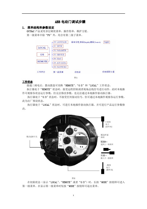
ABB电动门调试步骤1.菜单结构和参数设定ONTRAC产品采用多层树状菜单,操作简单,维护方便。
第一级菜单中除“P0”外,均含有第二级子菜单。
图1工作状态接通三相电后,拨动拨盘可切换“REMOTE”、“O/S”和“LOCAL”工作状态。
执行器处于“REMOTE”状态时,接受远程控制或者现场总线信号进行动作,此时本地操作可观察各状态运行参数,但无法修改参数,也无法通过本地操作驱动执行器。
执行器处于“O/S”状态时,不接受任何驱动信号,但可通过本地操作观察各运行参数,此为出厂预设状态。
执行器处于“LOCAL”状态时,可进行本地操作驱动执行器,并可进行产品运行参数修改。
图2在初始状态(显示“LOCAL”、“REMOTE”或者“O/S”)时,长按“MODE”按钮即可进入第一级菜单。
在显示第一级菜单时短按“MODE”按钮即可退出菜单。
在显示第一级菜单时,可通过“↑”和“↓”按钮进行本级菜单间的切换。
在菜单显示“P0 LANGUAGE”时,长按“MODE”按钮,即可进入语言设定,此时可见菜单显示“P0 ENGLISH”并闪烁,通过“↑”和“↓”按钮可切换至德文菜单,出厂预设为英文。
在第一级菜单显示“P1”~“P6”时,长按“MODE”按钮即可进入相应的第二级菜单。
在本级菜单间可通过“↑”和“↓”按钮进行切换。
短按“MODE”按钮即可退至上一级菜单。
设定值并保存在显示第二级菜单时,长按“MODE”按钮即可进入设定级。
以显示第二级菜单“P1.1 TORQUE—O”时为例,长按“MODE”时可进入开向停机力矩设定,菜单显示当前百份比力矩值和“TORQUE-O”,且数字闪烁,此时用“↑”和“↓”按钮可以调整开向力矩值。
达到调整值后,短按“MODE”按钮,如力矩值未变化,则直接退回到第二级菜单“P1.1 TORQUE_O”,如力矩值变化,则显示调整后的力矩值(此数字稳定)和“SAVE”(此字符闪烁)。
此时按“↑”和“↓”按钮可将“SAVE”切换至“CANCEL”,在“SAVE”状态短按“MODE”按钮,两秒钟后“SAVE”停止闪烁,自动退回至第二级菜单“P1.1 TORQUE_O”,并保存当前调整值,如在“CANCEL”状态短按“MODE”按钮可退回至第二级菜单“P1.1 TORQUE_O”,并不保存当前调整值。
ABB_电动机产品使用说明书
其它语种译本可向 ABB 索取。 ZH ă 2
ABB/低压电机/使用手册 ZH-EN 12-2004
ZH
低压电机
安装、操作及维护手册
目录
页
1. 一般说明 ......................................................................................................................................................... 4 1.1 符合性声明.......................................................................................................................................... 4 1.2 有效范围 .............................................................................................................................................. 4
此外,作为零部件,这些产品符合以下基本要求:
电磁兼容 (EMC) 指令 89/336/EEC(由 92/31/EEC 和 93/68/EEC 修订),该指令涉及辐射和 抗干扰水平的内在特性,
且符合:
EN 60 034-1
要求:
机器指令 98/37/EEC,该指令规定机器应由机器制造商正确安装(例如:符合本公司的安装说明和 EN 60 204“工业机器电气设备”)
低压电机
ABB电机说明书readdata.jsp

三相异步电动机使用维护说明书上海ABB电机有限公司2007年6月ABB电机使用维护说明书一、产品介绍1、适用范围本说明书适用于ABB各标准系列及其所派生的各种系列电机(防爆系列电机除外)。
机座中心高:56-355。
(对一些特殊应用场合或有特殊设计考虑的型号电机还需参阅其它特别的指导说明)。
二、一般要求1、起动1.1 收货检验∙收货后,立即检验电机有无外部损伤,检验所有的铭牌数据,尤其是电压和绕组的连接方式(Y 或△)。
∙用手旋转转轴,检测电机空转情况,如果电机装有锁定装置,注意将其打开。
1.2 绝缘性能检测∙电机初次使用之前,绕组有可能受潮,都要测量其绝缘阻值。
∙25℃时测量的绝缘电阻值应超过参考值,20×URi ≥ MΩ1000+2PU=电压 V, P=输出功率 kW[注意]测量后绕组要立即放电,避免电击。
∙周围环境温度每升高20℃,电阻的参考值减少一半。
∙如果没有达到绝缘电阻的参考值,绕组就必须烘干。
∙烘炉的温度为90℃,时间12-16小时。
∙如果安装了排水塞,烘干时必须将其打开。
∙绕组被海水浸泡后一般要重绕。
1.3 直接起动或 Y/△起动∙标准单速电机的接线盒一般有6个接线螺栓和至少1个接地螺栓。
∙电机通电之前,必须按规定要求可靠接地,不能接零代替接地。
∙电压和绕组连接方式在铭牌上有标注。
1.3.1 直接起动绕组可以采用 Y或△接法,例如660VY,380V△分别表示660V,Y接法和380V,△接法。
1.3.2 Y/△起动∙电源电压必须等于△接法电机的额定电压。
∙拆下接线板上所有的接线片,按Y/△起动装置接线,妥善连接到电机六个接线柱上,并能从起动初期的Y连接跳到启动完成的△接。
∙双速电机和其他特种电机的电源接法必须依照接线盒内的接线图说明。
1.4 接线柱和旋转方向∙如果电源相序U1,V1,W1依次与接线柱U1,V1,W1连接,从电机的驱动端观察转轴,其旋转方向为顺时针。
∙换接电源线中的任意两相就可以改变电机的旋转方向。
ABB Control - AC 31 1SBC 260xxx 中文名字说明书

AC 31 technical documentationChapter 1007CR42 / 07CT42This chapter gives you an introduction to the AC 31 automation, from the overall architecture to theoperational rules of the 07CR42 and 07CT42 central units.1. PresentationThe 07CR42 and 07CT42 central units bring accessibility to beginners and experienced automationusers alike, for any application with 14 to 110 inputs / outputs, using the same set of basiccomponents.It is therefore possible to realize applications throughout a site, a workshop, or a machine whereeach component (input / output unit, central unit) is close to the sensors / actuators. All informationfrom the sensors is sent after processing by the central unit to the actuators. The followingcommunication interfaces are available, to extend the AC 31’s possibilities and integration with thecompany's other automation systems: MODBUS®, ASCII.2. General set-up rulesAn ABB AC 31 system always includes an AC 31 central unit.Each 07CR42 and 07CT42 central units incorporate a specific number of binary inputs / outputs andanalog inputs. It is possible, to increase the number of inputs / outputs, to add input / outputextensions connected directly to the 07CR42 and 07CT42 central units.07CR42or 07CT42 XI16E1XO08R1 XC08L1 XM06B5Page 2ABB Control - AC 313. ReferencesProducts Description References Central units07 CR 42 - 24VDC Extensible stand-alone central unit,1SBP260023R1001with 8 isolated inputs 24 V d.c. and 6 incorporated relay outputs250 V a.c. / 2 Aand 3 analog inputs with 2 voltage inputs +/- 10 V and 1temperature inputRS232 interface for programming or ASCII or MODBUS®communication24 V d.c. power supply.1SBP260024R100107 CR 42 - 120/230VAC Extensible stand-alone central unit,with 8 isolated inputs 24 V d.c. and 6 incorporated relay outputs250 V a.c. / 2 Aand 3 analog inputs with 2 voltage inputs +/- 10 V and 1temperature inputRS232 interface for programming or ASCII or MODBUS®communication24 V d. c. power supply output to power inputs120 / 230 V a.c. power supply1SBP260025R100107 CT 42 - 24VDC Extensible stand-alone central unit,with 8 isolated inputs 24 V d.c. and 6 incorporated transistoroutputs 24 V d.c. / 0.5 Aand 3 analog inputs with 2 voltage inputs +/- 10 V and 1temperature inputRS232 interface for programming or ASCII or MODBUS®communication24 V d.c. power supply4. Technical specification 4.1. General characteristics07 CR 42 24 V d.c.07 CT 4224 V d.c.07 CR 42120/230 V a.c.Number of I/O- Incorporated binary inputs8- Incorporated binary outputs6- Incorporated analog inputs3- Analog potentiometers2- Maximum number of extensionunits per central unit6- Max. number of binary inputs104- Max. number of binary outputs54- Max. number of analog inputs51- Max. number of analog outputs12 Interfaces- CS 31 interface no- Interface for: ProgrammingMODBUS®or ASCII1 RS 232Memory- User program memory size:without ONLINE with ONLINE 17 000 words (typically: 8.5 kInstructions) 8 000 words (typically: 4 kInstructions)- User program memoryand the constantsFlash Eprom - Data memory SRAM- Data backup:Backup autonomyCharge time under power yes with battery 20 days at 25°C 100% in 12 hWeight400 g800 gPage 4ABB Control - AC 314.2. Functionality and programming07 CR 42 24 V d.c.07 CT 4224 V d.c.07 CR 42120/230 V a.c.- Execution time for 1kbytes:100% binary instructions 65% binary, 35 % words 0.4 ms1.2 ms- Internal bits2016 - Internal words2016 - Internal double words128 - Chain steps2016 - Word constants496 - Double word constants127- TimersTime range42 simultaneouslyfrom 1 ms to 596 h 30 (24 days + 20 h 30)- CountersCounter rangeunlimited- 32767 to + 32767- High speed counter function:Incremental encoder Stand-alone counter1 with max frequency 5 kHzon the I62.00 and I62.01 inputs2 at 7 kHz on the I62.00 and I62.01 inputs- Interruptions:by alarm (on rising edge) cyclicmax length250 µs delay2 on the I62.02 and I62.03 inputs1 (from 1 ms to2 s)3 ms- Command output of step motorwith frequency modification(cyclic ratio = 50%)10 Hz to 2.66 kHz- User program protection in thecentral unityes with password- Clock Drift (typical) 4.3 min / month at 25°C- Programming software AC31GRAF under Windows® (IEC 1131-3) - Programming language FBD/LD : Function blocks and ladderdiagramsQuick LD: Ladder diagramIL: Instruction listSFC: Sequential function chart- Program execution sequentialtriggered by clock ortriggered by alarm (interruptions)- Sub-program: Level 12 1- Operation set:Basic functionsAdvanced functions Boolean, arithmetic, comparisonover 804.3. Power supply07 CR 42 24 V d.c.07 CT 4224 V d.c.07 CR 42120/230 V a.c.Power supply- Power supply voltage:Nominal valueAdmissible range24 V d.c.19.2 to 30 V120 / 230 V a.c.97.75 to126.5 V or195.5 to 253 V- Consumption:central unit alone typical. Maximum configuration typical.120 mA400 mA60/30 mA100 mA- Polarity reversal protection yes no- 24 V d.c. isolated power for the inputs:Voltage rangeOutput currentShort circuit protection no---yes19.2 to 30 V400 mAyes- Dissipation 5 W (6 W for 07 CT 42)10 W 4.4. Incorporated binary inputs07 CR 42 24 V d.c.07 CT 4224 V d.c.07 CR 42120/230 V a.c.- Number of inputs888- Isolation of inputs / electronic1500 V a.c.1500 V a.c.1500 V a.c.- Input types PNP orNPN PNP orNPNPNP orNPN- Input voltage:Nominal valueSignal at 0 (IEC 1131-2) Signal at 1 (IEC 1131-2)24 V d.c.0 to + 5 V+ 15 to + 30 V24 V d.c.0 to + 5 V+ 15 to + 30 V24 V d.c.0 to + 5 V+ 15 to + 30 V- Input current at 24 V d.c.:Inputs I62.02 to I62.07 Inputs I62.00 and I62.017 mA9 mA7 mA9 mA7 mA9 mA- Filtering time:Standard inputInput with counter configuration Input with interruptionconfiguration 5 ms70 µs90 µs5 ms70 µs90 µs5 ms70 µs90 µs- Cable length:Unshielded (not for the high speed counter inputs)ShieldedNon standard inputs 300 m500 m50 m300 m500 m50 m300 m500 m50 mPage 6ABB Control - AC 314.5. Incorporated binary outputs07 CR 42 24 V d.c.07 CT 4224 V d.c.07 CR 42120/230 V a.c.- Number of outputs 6 relays 6 transistors 6 relays- Isolation of the outputs / electronic1500 Vrms1 min 1500 V a.c.1500 Vrms1 min- Total charging current under voltage:direct 24 V d.c.resistive load / inrush current L / R = 20 msL / R = 30 msL / R = 40 msL / R = 60 msalternate 24 to 230 V a.c.2 A / 5 A2 A1 A0.6 A0.35 A2 A AC-10.5 A AC-151 A forO62.00 andO62.01 and0.5 A forother outputs-2 A / 5 A2 A1 A0.6 A0.35 A2 A AC-10.5 A AC-15- Total charging current 6 x 2 A 4 x 0.5 A+ 2 x 1 A6 x 2 A - Output leakage current-< 200 µA-- Output waste voltage-0.5 V to500 mA max.-- Minimum cut-off values10 mA under12 V d.c.12 V10 mA under12 V d.c.- Breaking capacity under 120 V a.c.(contact rating code B300) (UL)2 A 2 A- Breaking capacity under 250 V a.c. (contact rating code B300) (UL)2 A (1.5 Aaccordingto UL)2 A (1.5 Aaccordingto UL)- Number of common 2 (2+4) 2 (2+4) - Switching frequency:for resistive loads for inductive loads for lamps< 1 Hz< 0.2 Hz< 0.2 Hz5 kHz< 1 Hz< 0.2 Hz< 0.2 Hz- Number of switches:for AC-1 for AC-151 million100 000--1 million100 000- Short circuit and overload protection envisageexternallyyes:thermicenvisageexternally- Surge voltage protection envisageexternally yes envisageexternally- Outputs diagnosis no overload andshort circuitno - Cable length:unshielded shielded 150 m500 m150 m500 m150 m500 m4.6. Incorporated analog inputs4.6.1. Technical characteristics07 CR 42 24 V d.c.07 CT 4224 V d.c.07 CR 42120/230 V a.c.- Number of analog inputs:Voltage Temperature 212121 Voltage Temperature- Nominal range:Maximum values :+/- 10 V+/- 30 VRTD10Ω up to 7MΩ- Resolution11 bits + sign( 5 ms )12 bitsPt100Pt1000 - Min resolution at input (± 1LSB)+/- 2,5 mV0.6° C0.3° C - Full scale precision≤+/- 1%≤+/- 2%- Word value range read by the central unit +/- 32767Full scale dependson the type of sensor- Amplification error between twochannels70 dB70 dB- Input impedance>20 kΩ>20 kΩ- Linearization for Pt 100 / Pt 1000By FKG functionblock- Sampling rate 2.5 ms 2.5 ms- filtering time0.5 ms50 ms- Diagnosis No No- Cable length:shielded 50 mYes50 mYesPage 8ABB Control - AC 314.6.2. Cabling of the analog inputsExample : connection on 07CR42 120/230 V a.c.The 3 analog inputs are not electrically isolated.Warning: the connector for analog inputs is different of connector for binary inputs.Use rigid or multi-conductor AWG 18 (0.96 mm2) to AWG 14(1.95 mm2) wires for binary inputs and the rigid or multi-conductor AWG 14(1.95 mm2) wires for the binary outputs.And use rigid or multi-conductor AWG 28 (0.08 mm2) to AWG 16(1.5 mm2) wires for analog inputs.The address 62 is assigned to the analog inputs.-IW62.02 Voltage format-IW62.03 Voltage format-IW62.04 Temperature formatAssignment of the 3 analog inputs4.6.4. Voltage format on analog inputThe voltage format is only available on the analog inputs IW62.02 and IW62.03Measuring ranges ±10 V 11 bits resolution plus sign.1 LSB = 20 / 212 = 4,88 mV with minimum value ( step 8 )Value = [ V ( in volt ) / 10 ] * 32767 with value ( - 32767 ≤ X ≤ + 32767 )1514131211109876543210- 105 2.5 1.256253131567839201050000Sign V V V mV mV mV mV mV mV mV mV0Relationship between the measured values and the positions of the bits in the 16-bit wordThe value range corresponds to the numbers - 32767…. + 32767Range overflow: + 32767 , range underflow: -32767Warning:Without connection or Open-circuit, the analog value read in the user program is:= +10800 (+/- 1%) corresponding to around 3.5 voltsShort-circuit : 0 (+/- 1%)Fast reading with fix frequency, independently of the cycle time, around 2.5 ms4.6.5. Current format 4 - 20 mAThe analog inputs IW62.02 and IW62.03 can be also configure in current format 4-20 mA in usingan external additional resistance in parallel of the analog input.In the same time, inside user program, it is necessary to use calculation function blocks or directlyFKG function blocks (just two couple of points is enough) in order to converter the read analogvalue in value corresponding to current format.To choose the right additional resistance, you have first to check the technical data of the currentsensor and identify the Max load resistance allowed.The resistance should be less than 500 Ohms, and according to the value chosen, it is possible todeterminate the resolution:For R = 500 Ohms => dynamic 2/10V resolution around 11 bitsFor R = 250 Ohms => dynamic 1/5V resolution around 10 bitsFor R= 125 Ohms => dynamic 0.5/2.5V resolution around 9 bitsPage 10ABB Control - AC 314.6.6. Temperature format on analog inputsThe analog input IW62.04 can be used with all universal temperature sensors like PT100, PT1000, PTC or others…. The analog input can be configured individually in a lot of different operating temperature modes.The complete table of corresponding resistance / analog value can be found in § annexes.The configuration will be performed by FKG function block, this function allows to define a curve by n points ( X0 / YO… Xn-1 / Yn-1 ) and this function block make a linear interpolation between the interpolation points. The resulting curve representing the relationship between X and Y will be the current analog value.-X will correspond at the current analog value of IW62.04-Y value according to the table corresponding Resistance / Analog value(further details can be found inside software manual AC31GRAF - 1SBC006099R1101 – Volume C and Chapter “High order functions”)4.6.6.1 Configuration for PT100 sensor (Platinum 100 W / 0°C)Value = ( 32737 * R ) / ( R + 768 )The measuring range for PT100 is 12 bits,the value range: (-100.3 to +524.4 °C) by FKG function blockrange overflow / open-circuit: : +32688,range underflow / short-circuit of the sensor : 0Example of configuration PT100 sensor with FKG function block:Possibility of using only a point everything them 30 °C to assure a precision lower than0.5 °C for PT100 sensor. (the values can be found in table next § 4.6.6.2.)4.6.6.2 Table of corresponding Resistance / Analog value / ° Celsius /° Fahrenheit for PT100 sensorsPage 12ABB Control - AC 314.6.6.3 Configuration for PT1000 sensor (Platinum 100 W / 0°C)Value = ( 32737 * R ) / ( R + 768 )The measuring range for PT1000 is 12 bits,the value range: (-100.3 to +524.4 °C) by FKG function blockrange overflow / open-circuit: : +32688,range underflow / short-circuit of the sensor : 0Example of configuration PT1000 sensor with FKG function block:Possibility of using only a point everything them 20 °C to assure a precision lower than 0.3 °C for PT1000 sensor. (the values can be found in table next § 4.6.6.4.)4.6.6.4 Table of corresponding Resistance / Analog value / ° Celsius /° Fahrenheit for PT1000 sensorsPage 14ABB Control - AC 314.6.7. configuration with another temperature sensor typePossibility to use another temperature sensors like PTC, NTC…etc…The configuration will be performed also by FKG function block, the parameters can be found according to the characteristics temperature sensor type used in the complete table of corresponding resistance / analog value (see in § annexes)Example with PTC thermistor, thermal machine protection, use to protect electric motors from over temperature. The resistance / temperature characteristics of PTC thermistor is defined by theTypical characteristics curve R(°C) for PTC thermistorWith T = limit to protect electric motorExample:- with PTC 80 T = 80°C corresponding to about 1000 Ω- with PTC 120 T = 120°C corresponding to about 1000 ΩUse the corresponding analog value in user program (comparison functions) to realise the protection motor. Possibility also to use several PTC thermistors connected in series and use the additional resistance values of different thermistors before to use the analog value corresponding in the user program.4.6.8. Diagnosis identificationValues for the different version of 42 series of correspondence table between the error and the diagnosis variable values are:- Unit type:22807CR42- Unit type:22907CT42(further details about diagnosis procedure can be found inside Technical manual AC31 -1SBC260400R1001 –Chapter 8 “Diagnosis”)4.6.9. Overview of electrical isolations120/230VACElectrical of isolation for 07CR42 – 120/230VACElectrical of isolation for 07CR42 – 24VDCElectrical of isolation for 07CT42 – 24VDCPage 16ABB Control - AC 314.6.10. AnnexesComplete table of corresponding Resistance / Analog value for only IW62.04Page 18ABB Control - AC 31Page 20ABB Control - AC 31。
ABB(EM800)电动执行机构操作说明书

智能MME800系列调节型 S4-25%/1200次/小时 多转式电动执行器 扭矩30~125 N ·m 操作说明 速度7~35 r/min(用于1.06版本软件的执行器) 10/78—1.05 CN■ 应用本电动执行器结构坚固耐用,适用于操纵端控制元件,广泛应用于能源、化工、石油与天然气、水与污水处理等行业。
附加的齿轮传动装置(用于有限转角、直线运动)能与各种类型的阀门相互匹配使用。
智能型多转式执行器具有多种扩展功能,如自诊断功能,大大地简化了调试工作并可加快工程进度。
MME800系列执行器可以通过使用方便的红外通讯接口或任选的总线接口进行通讯。
模块式结构,规格精简,降低用户备品备件库存量辅助的速度控制能确保在微偏差调节中获得很高的定位精度目录1.适用范围。
2 2.菜单结构和参数设定。
2 3.电气连接。
6 4.红外通讯。
9 5.故障与意外情况处理。
10 6.现场总线。
11 7.附言。
121. 适用范围本操作说明适用范围为软件版本1.06的ONTRAC MME800全系列产品,也可供MOE700全系列产品使用参考。
2. 菜单结构和参数设定ONTRAC产品采用多层树状菜单,操作简单,维护方便。
第一级菜单中除“P0”外,均含有第二级子菜单。
图1工作状态接通三相电后,拨动拨盘可切换“REMOTE”、“O/S”和“LOCAL”工作状态。
执行器处于“REMOTE”状态时,接受远程控制或者现场总线信号进行动作,此时本地操作可观察各状态运行参数,但无法修改参数,也无法通过本地操作驱动执行器。
执行器处于“O/S”状态时,不接受任何驱动信号,但可通过本地操作观察各运行参数,此为出厂预设状态。
执行器处于“LOCAL”状态时,可进行本地操作驱动执行器,并可进行产品运行参数修改。
图2在初始状态(显示“LOCAL”、“REMOTE”或者“O/S”)时,长按“MODE”按钮即可进入第一级菜单。
在显示第一级菜单时短按“MODE”按钮即可退出菜单。
ABB 3.1 AC 1300 电子开关及脚杆开关说明书
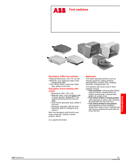
ABB Control Inc.3.18/00Description of Mini foot switches• Reduced dimensions: 100 x 75 x 34 mm.• Materials: cover and base made of self-extinguishing ABS.• Color choice: black or grey base; black,grey, yellow or red cover.Description of foot switches with covers•Dimensions: 285 x 140 x 145.•Materials: base, cover and pedal made of shock resistant Bayblend ® FR 90material (alloyed polycarbonate and ABS).•Color choice: grey base; grey, yellow or red cover.•Variations: grey base, half-red cover.Especially used for emergency stop function.Note: this emergency stop function must never contain the «locked in neutral position » device.UL Listed file #E191693ApplicationFoot switch-operated machines such as:shearing machines, folding machines,spinning lathes, machine tools, wrapping machines, riveting presses, etc.Foot switches with covers come in three operation formats:•Free movement: contact position follows pedal movement: actuated when the pedal is pushed down, released when pedal is in a state of rest.•Foot switch locked in neutral position:same operation as above, after unlocking the pedal with the end of the foot.•Foot switch latched in low position:same operation as free movement,except that a state of rest is obtained only after having unlatched the pedal with the end of the foot.3.2ABB Control Inc.8/00Foot switchesIPM Mini foot switches, IPS Foot switches with covers DescriptionComment: Foot switches with covers can be assembled on a plate and equipped with a transportation handle. Upon request, instead of thehandle an emergency stop button can be installed above a tube that allows for connection cable passage.ApplicationFoot switch-operated machines such as: shearing machines, folding machines, spinning lathes, machine tools, wrapping machines, riveting presses, etc.Foot switches with covers come in three operation formats:•Free movement: contact position follows pedal movement:actuated when the pedal is pushed down, released when pedal is in a state of rest.•Foot switch locked in neutral position: same operation as above, after unlocking the pedal with the end of the foot.•Foot switch latched in low position: same operation as free movement, except that a state of rest is obtained only after having unlatched the pedal with the end of the foot.Description of Mini foot switches• Reduced dimensions: 100 x 75 x 34 mm.• Materials: cover and base made of self-extinguishing ABS.• Color choice: black or grey base; black, grey, yellow or red cover.Description of foot switches with covers•Dimensions: 285 x 140 x 145.•Materials: base, cover and pedal made of shock resistant Bayblend ® FR 90 material (alloyed polycarbonate and ABS).•Color choice: grey base; grey, yellow or red cover.•Variations: grey base, half-red cover. Especially used forABB Control Inc.3.38/00Foot switches Mini foot switchesIPM Mini foot switchesIPM1RMini foot switch Cover color Y - yellow G - grey B - black R - redBase color 1 - black 2 - greyCatalog number explanationIPM1YIPM1YIPM1GIPM1BIPM1RDiscount schedule RM3.4ABB Control Inc.8/00Foot switchesFoot switches with coversIPS foot switchesTo select a foot switch color, substitute the appropriate color code for the 5 in the catalog numberColor codeYellowY Grey G RedRContact blocks11 - 1 N.O. contact + 1 N.C. contact 22 - 2 N.O. contacts + 2 N.C. contactsCover color Y - yellow G - grey R - redZ - half-red cover 11 - Free movement2 - Foot switch locked in neutral position3 - Foot switch latched in low positionA - Za Snap actionD - Zb Slow action non-overlapping late makePlain foot switch with cover Catalog number explanationIPS Y1 A 111Incompatible with locked in neutral position function.Discount schedule RMABB Control Inc.3.58/001 2 3510Current (A)Current (A)1 2 3 5100.2 0.30.5Technical data3.6ABB Control Inc.8/00Technical data Mini-footswitchesDimensions (mm )N.O. + N.C. Contact blockIPM Mini foot switchesABB Control Inc.3.78/00Technical dataFoot switches with coversDimensions (mm )Plain foot switch a = pre-travel b = total travelExample of double foot switch utilization。
【VIP专享】ABB使用说明书最新版

前言衷心感谢您使用“华振”牌智能变频供水设备,我们将为您提供优质的产品和星级的售后服务。
我公司吸取行业内智能变频供水设备的技术精髓,集长期从事水泵行业和智能变频供水设备的设计经验,研制开发的ZBH第三代、第四代、第五代、第六代智能变频供水设备,已广泛运于高层建筑、住宅楼、商住楼、新老小区降耗节能改造、高级宾馆、医院、学校、工矿企业的生产生活用水等,是一种节能型,现代化,智能化的变频供水设备。
本使用说明书向您详细介绍了“华振”牌系列智能变频供水设备的产品说明、技术说明、操作、故障处理,保养维护等各方面内容。
为了更好的使用智能变频供水设备,请您在操作前仔细阅读本说明书,这将会:●帮助您了解智能变频供水设备的结构及性能特点。
●避免由于操作不当而引起的设备故障。
●提高设备的使用寿命。
●增强设备使用的可靠性。
值得注意的是,本说明书的资料及图形在出版时是正确的,但我公司产品的结构和性能总在不断地改进和完善,本说明书的相关内容可能有变化,恕不一一通知,敬请谅解。
感谢您对“华振”的信任,衷心地祝愿您在事业中大展宏图,取得辉煌成就。
成都华振供水设备有限公司- 1 -))1 MΩ电阻与机壳连接用于模拟输入电位器的给定电压输出.10 V±2%))1 MΩ电阻与机壳连接频率。
0…20 mA ( 数字输入6,可编程。
默认Ω。
数字输入最大电压一般显示性能软键功能每个软键上方的文字描述的是当前软键功能的含义。
显示对比度同时按住 MENU (菜单)键和 UP (向上)或DOWN (向下)可以改变显示对比- 5 -顶行液晶屏的顶行显示变频器的基本的状态信息。
• LOC (本地) - 表示变频器处于本地控制,即控制命令来自控制盘。
• REM (远程) - 表示变频器处于远程控制, 例如 I/O (X1) 或现场总线。
• - 显示变频器和电机的旋转状态:4、应用宏的选择 中崛供水设备应用宏选择,用于泵的循环软起控制中,在ABB 变频器设置中9902的值为15(SPFC 控制).注意! 参数2108 START INHIBIT (禁止起动)必须保持为默认设置0 (OFF)。
- 1、下载文档前请自行甄别文档内容的完整性,平台不提供额外的编辑、内容补充、找答案等附加服务。
- 2、"仅部分预览"的文档,不可在线预览部分如存在完整性等问题,可反馈申请退款(可完整预览的文档不适用该条件!)。
- 3、如文档侵犯您的权益,请联系客服反馈,我们会尽快为您处理(人工客服工作时间:9:00-18:30)。
Power Electronic Units for Field Installation 给现场装置供电使之能够工作EAN823, EBN853, EBN861 (Contrac) EAN823, EBN853, EBN861 (Contrac)For the Control of Contrac Actuatorsof the PME, LME, RHD or RSD Series PME, LME, RHD or RSD系列的Contrac激励的控制Content 目录1设备说明 (2)2 应用 (3)3 概要 (3)3.1 正确用法 (3)3.2 安全和预防 (3)4 存放4.1 长期存放 (3)5 交货设置 (3)6 汇编6.1 EAN823 / EBN853 (4)6.2 EBN861 (5)7 技术参数7.1 一般的…………………………………………………………………………………67.2 EAN823的电流消耗…………………………………………………………………67.3 EBN853的电流消耗…………………………………………………………………77.4 EBN861的电流消耗…………………………………………………………………77.5 保险丝…………………………………………………………………………………78 装备8.1 准备电.............................................................................................88.2 EAB823 / EBN853的装备 (8)8.3 EBN861的装备 (8)9 电路接线9.1 EAN823 / EBN853 / EBN861(标准的) (9)9.2 EAN823 / EBN853 / EBN861(现场总线数据处理)....................................99.3 电缆套管..........................................................................................109.4 输入/ 输出信号 (10)9.5 插头接线 (11)13 结构13.1 控制面板的结构(联接控制协议) (12)13.2 调节器所用的程序 (13)13.3 控制面板的功能和信号 (13)14 警告/ 故障14.1 解说 (15)14.2 警告摘要 (15)14.3 故障摘要 (16)15 故障及处理方法 (17)LegendDangerIndicates an imminently hazardous situation which, if not avoided, will result in death or serious injuryWarningIndicates a potentially hazardous situation which, if not avoided, could result in death or serious injury or serious property damage.CautionIndicates a potentially hazardous situation which, if not avoided, may result in minor or moderate injury or property damage.ImportantIndicates useful hints or other special informati on which, if not observed, could lead to a decline in operating convenience or affect the functionality.1.Device Identification 设备验证1.1 General 概述The ID labels of the power electronics are located both 设备名牌在本体(电源部分)标注带电位于底部两边on the base (power supply) and on the cover (electronics(电源)在盖子上面(电和盖子封面上。
and software memory) of the unit. As the base and cover和存储软件)个体底部和封面are considered as separate assemblies, they may have考虑过的单独的装配他们可以有本体和盖面单独生产然后装配,different serial numbers (F. no.).不同的编号它们可以有不同的编号。
1.2ID Label on the Base 1.2本体标签5.Delivery settings 移交细则0/100%内的动作用额定转距保持关闭状态配置功能线性;输入:4 ... 20 mA功能远程位置调节器,参数输出 4 ... 20 mA数字输入数据输入跳闸手动/自动DI 2 / DI 3 manual control +/-手动控制Digital outputs: DO 1 ready to operate, DO 2/3 end position signalling 数字输出准备好操作决定发信号的位置Range :Not adjusted (to be adjusted during commissioning)范围不调整(在试车期间调整)he configuration of your actuator may differ from the standard configuration specified above. 从标准的清单上看你actuator的配置可以不同It can be called up for display using a notebook / PC and the related configuration program. 它可以用笔记本/个人电脑陈列配置的表not with fieldbus communication.不要野外通讯6.Assemblies 装配Power electronics EAN823, EBN853 and EBN861 consist of 2 parts each, one containing the connecting units (EAN823 and EBN853) and the transformer, the other containing the electronics and the local control panel (LCP) for local operation and adjustment of the actuator.EAN823, EBN853 and EBN861的电源由两个相互独立的部分组成,一部分包含接头(EAN823 and EBN853)和变压器,另一部分包含就地控制面板用来现场操作和调试。
图片1:EAN823的电动部分图片2:EBN853的电动部分1 taphole for cable glands2 cover for connection chamber3 connection housing4 electronic hod5 cover for local control panel1 穿线孔2 接线盒3 固定部分4 电箱5 就地控制面板图3 :EAN823 / EBN853的接线盒The standard scope of delivery considers tapholes covered with srew-in plugs. Adapters for PG or NPT cable glands are available on request.按标准交货时传闲空应该塞上。
配备合适的接头是很有用的。
接线盒 电源保险 信号端子 接保险和加热器的端子 电机端子 主保险总电源接线端子电缆接头穿线孔就地控制面板盖用螺钉连接螺钉 变压器和电源 连接螺钉 盖用螺钉 电器部分盖子电机电源线入口电机刹车 主电缆接线端子 信号接线端子 信号电缆入口7.技术资料工作台1PROFIBUS DP通讯不了7.2 Current Consumption of EAN823 当前通用EAN823each around 各自周围7.5 Fuses 保险丝Electronic 保险类型安装地点U = 115 V U = 230 V 1) unitEAN823 外部保险外部16 A, 慢主保险接线盒内 6.3 A, 慢 3.15 A, 慢模拟量信号输入接线盒内 40 mA; 快防潮加热器接线盒内 2 A; 慢EBN853 外部保险外部16 A, slow主保险接线盒内12.5 A, slow 10 A, slow模拟量信号输入接线盒内40 mA; fast刹车保险、动力板0.315 A, 中间时间间隔中间电路保险动力板10 A, 极快防潮加热器接线盒内 2 A; slowEBN861 外部保险外部35 A fuse-- 16 A 安全熔断刹车保险功率板上0.315 A,-- 中间有时间间隔中间电路保险功率板上15 A, 中间有时间间隔The 35 A fuse and the thermal safety cutout (16 A) are included in the scope of delivery. They ensure safe operation for the special swiching conditions of power electronics EBN861. Note that the cable cross-sectional area between the fuse and the electronics must be at least 2.5.35A保险和安全熔断保险(16A)是包含在交货范围内的。
它们确保EBN861安全运行的专用保险。
注意:保险与电路的连接处必须保证至少2.5平方毫米。
7.5.1 External fuses for EBN861Apart from the internal fuses (see also 7.5), the EBN861 power electronic unit requires two additionalexternal fuses, which are supplied separately to the unit.7.5.1 EBN861的外部保险部分保险是国产的(同样是7.5),EBN861 电源需要两个外部保险,用来替换。