蓝牙模块规格书
KC-01蓝牙模块说明书-VER1.1

KC-01蓝牙模块规格书一.模块功能描述KC-01模块是一个高集成度,低成本,低功耗的蓝牙立体声带通话功能+U盘+TF卡+FM+Line in全功能单芯片模块,符合V4.2+BR+EDR+BLE规范。
1.可播放MP3/WAV;2.蓝牙立体声传输,蓝牙通话;3.支持76-108MHZ FM收音;4.TF/SD卡控制,支持USB功能,可以实现读卡器功能;5.立体声Line-in输入;6.IR遥控;7.两个可控LED、支持外部功放mute功能;8.内部集成电源管理(根据SDK的支持而调整);9、支持U盘控制;10、带高速UART调试及升级接口。
二.模块产品应用该模块主要用于短距离的音乐传输,可以方便地和笔记本电脑,手机,PDA等数码产品的蓝牙设备相连,实现音乐的无线传输,由于集成了FM与MMC卡的播放功能,使本产品具有有极高的性价比。
三.模块产品规格蓝牙版本V4.2+BR+EDR+BLE调制方式PSK 3Mbps,π/4-DQPSK和8DPSK支 持HFP/HSP,OPP,A2DP/AVRCP,PBAP profiles灵敏度(0.1% BER) -85dBm发射功率满足class2 and class3的发射功率要求,可以提供+2dbm的发射功率供电电压DC 3.2V~4.2V耗电电流正常工作电流25mA,播放暂停时12mA信 噪 比>90dB工作温度-20 ~ +50℃尺 寸23mmx13mm x2.05mm四.模块详细尺寸五.模块PIN脚说明PIN脚序号 名称 功能说明1,,24 GND GND2 USBDM USB Negative Data;ISP_DI:3 USBDP USB Positive Data;ISP_DO:PA3 AMUX1L:Simulator Channel 1 Left;Touch10:Touch Input Channel 10;ADC0:ADC Input Channel 0;UART2TXA:Uart2 Data Out(A);ISP_CLK:Wakeup8:Port Interrupt /Wakeup 8; 4PWM0H/ADC0/PA5 UART0TXA:Uart0 Data Out(A);Touch12:Touch Input Channel 12;ADC2:ADC Input Channel 2;IIC_SCL_D:IIC SCL(D);Wakeup9:Port Interrupt /Wakeup 9;5 MIC MIC6 DACR DAC Right Channel7 DACL DAC Left Channel8 VCOMO DAC Reference out9 DACVDD DAC Power10 AGND DAC Ground11 FMIP FMIP12 VDDIO POWER 3.3V13 PB12/SD0CLKGPIO AMUX2R:Simulator Channel2 Right; NFCRX:NFC Data InTouch7:Touch Input Channel 7; ADC11:ADC Input Channel 11;SPI1DOA:SPI1 Data Out(A);SD0CLKB:SD0 Clk(B);14 PB11/SD0CMDGPIO AMUX2L :Simulator Channel2 Left; NFCTX:NFC Data OutTouch6:Touch Input Channel 6; ADC10:ADC Input Channel 10;SPI1CLKA:SPI1 Clk(A);SD0CMDB:SD0 Command(B); Wakeup13:Port Interrupt /Wakeup 13;PB7 GPIO UART0RXB:Uart0 Data In(B); ADC6:ADC Input Channel 6; TMR3:Timer3 Clock Input;15PB10/SD0/DAT/ADC9/PWM3H GPIO UART2RXC:Uart2 Data In(C); Touch5:Touch Input Channel 5; ADC9:ADC Input Channel 9; SPI1_DI A:SPI1 Data In(A);SD0DAT 0B :SD0 Data 0(B); CAP0:Timer0 Capture;16 LDOIN Charge Power 5v 17 VBAT LDO Power18 PR1/ADC12 RTCIO1; ADC12:ADC Input Channel 19PR2/OSC32KORTCIO2; ADC13:ADC Input Channel 13;OSC32KI;20 PR0/OSC32KO/ RTCIO0;OSC32KO21SPI1DOB/SD1CLKA/PC5GPIO ;SD1CLKA :SD1 Clk(A); SPI1DOB :SPI1 Data Out(B); UART2RXD :Uart2 Data In(D) IIC_SDA_B :IIC SDA(B); 22 SPI1CLKB/SD1CMDA/PC4GPIO ;SD1CMDA :SD1 Command(A); SPI1CLKB :SPI1 Clk(B);UART2TXD :Uart2 Data Out(D); IIC_SCL_B :IIC SCL(B); PC2/SD1DAT1A :SD1 Data1(A); UART0TXC :Uart0 Data Out(C); CAP1:Timer1 Capture; 23PWM5L/SPI1DIB/SD1DATA/PC3SD1DAT0A :SD1 Data0(A); SPI 1DI B:SPI 1 Data In(B ); UART0RXC :Uart0 Data In(C)六.应用原理参考七.使用注意事项A.关于无线蓝牙的使用环境,无线信号包括蓝牙应用都受周围环境的影响很大,如树木、金属等障碍物会对无线信号有一定的吸收,从而在实际应用中,数据传输的距离受一定的影响。
CSR57F68蓝牙模块F-3088版本V6.0规格书
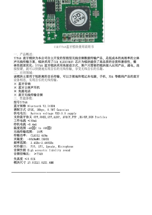
深圳市晨兵电子有限公司 咨询请联系:彭巨松 电话:135902152837 QQ:1825598678 CSR57F68蓝牙模块使用说明书一.产品概述:接按键,就可以快捷地实现音乐的无线传输,享受无线音乐的乐趣。
二.应用领域:设备相连,实现音乐的无线传输。
三.性能参数:四、模块尺寸图:五、模块脚位定义图六、引脚功能说明Pin Symb I/O Description1 PIO1 Bi-DirectionalTXEN2 PIO2 Bi-Directional Speakeroutput positive (left side)3 VOL+ Bi-Directional Speaker output negative (right side)4 VOL- Bi-Directional Speaker output positive (right side)5 UP Bi-Directional Ground6 DOWN Bi-directional Programmable input/output line7 POWER Bi-directional Programmable input/output line8 +1.8V POWER +1.8VSupply9 GND Bi-directional Programmable input/output line10 BAT Batteryterminal+ve 3.3-4.2V11 LED1 CMOS Input Synchronous Data Input12 LED2 pen drain output Synchronous Data Sync13 MIC pen drain output Synchronous Data Clock14 SPBN Analogue output Speaker output L negative15 SPBP Analogue output Speaker output L positive16 SPAN Analogue output Speaker output R Nositive17 SPAP Analogue output Speaker output R Positive18 GND GND Ground19 MOSI CMOS input with weakinternal pull-down Serial peripheral interface data input20 CLK CMOS input with weakinternal pull-downSerial peripheral interface clock21 CS# CMOS input with weakinternal pull-down Chip select for serial peripheral interface, active low22 MISO CMOS input with weakinternal pull-down Serial peripheral interface data Output23 RTS CMOSoutput,tri-state,withweek pull-upUART request to send active low 24 VDD-CHG Charger input Lithium iion/polymer battery七.工作模式:1模块通电(3.0v--------4.5v)2长按POWER键开机,这时LED1会闪动一次,接着灭掉,然后LED2在不停的闪动,如果连接上蓝牙设备,闪动频率大概5秒一次,表示模块在工作了,没有连接上大概2秒闪动一次。
亿佰特 E73-2G4M04S1A nRF52810 2.4GHz BLE4.2 5.0 低功耗蓝牙
E73-2G4M04S1A产品规格书nRF52810 2.4GHz BLE4.2/5.0 低功耗蓝牙模块第一章概述1.1 简介E73-2G4M04S1A是基于挪威Nordic生产的nRF52810为核心自主研发的小体积的贴片式蓝牙无线模块,采用32MHz高精度低温漂有源晶振,保证其工业特性和稳定性能。
nRF52810自带高性能ARM CORTEX-M4内核与蓝牙4.2和蓝牙5.0的射频收发器与协议栈,并拥有 UART、I2C、SPI、ADC、DMA、PWM 等丰富的外设资源。
模块引出了几乎所有的 IO 口,具体请查看引脚定义,方便用户进行多方位的开发。
模块内置PCB天线并可通过IPEX外接其他天线。
该产品已获得FCC、CE、RoHS等国际权威认证报告,用户无需担忧其性能。
由于该模块是纯硬件类SoC模块,需要用户对其编程后方可使用。
1.2 特点功能⚫支持BLE 4.2、BLE 5.0;⚫最大发射功率2.5mW,软件多级可调;⚫内置32.768kHz时钟晶体振荡器;⚫支持全球免许可ISM 2.4GHz频段;⚫内置高性能低功耗Cortex-M4核处理器;⚫丰富的资源,192KB FLASH,24KB RAM;⚫支持2.0~3.6V供电,大于3.3V供电均可保证最佳性能;⚫工业级标准设计,支持-40~+85℃下长时间使用;⚫双天线可选(PCB/IPEX),用户可根据自身需求选择使用。
⚫理想条件下,通信距离可达100m;1.3 应用场景⚫智能家居以及工业传感器等;⚫安防系统、定位系统;⚫无线遥控,无人机;⚫无线游戏遥控器;⚫医疗保健产品;⚫无线语音,无线耳机;⚫汽车行业应用。
第二章规格参数2.1 极限参数主要参数性能备注最小值最大值电源电压(V)0 3.6 超过3.6V 永久烧毁模块阻塞功率(dBm)- 10 近距离使用烧毁概率较小工作温度(℃)-40 +85 工业级2.2 工作参数主要参数性能备注最小值典型值最大值工作电压(V) 1.8 3.3 3.6 ≥3.3V 可保证输出功率通信电平(V) 3.0 使用5V TTL 有风险烧毁工作温度(℃)-40 - +85 工业级设计工作频段(GHz)2379 2430 2496 支持ISM 频段功耗发射电流(mA)18 瞬时功耗接收电流(mA)13休眠电流(μA) 2 软件关断最大发射功率(dBm) 3.8 4 4.3接收灵敏度(dBm)-94 -95 -96 空中速率为1Mbps主要参数描述备注参考距离100m 晴朗空旷,天线增益5dBi,高度2.5米,空中速率1Mbps 晶振频率24MHz/32.768KHz支持协议BLE 4.2/5.0封装方式贴片式接口方式 1.27mmIC全称nRF52810-QFAABB/QFN48FLASH 192KBRAM 24KB内核ARM CORTEX-M4外形尺寸17.5*28.7mm天线接口PCB/IPEX 默认PCB板载天线,等效阻抗约50Ω第三章机械尺寸与引脚定义引脚序号引脚名称引脚方向引脚用途0 GND 输入地线,连接到电源参考地1 GND 输入地线,连接到电源参考地2 GND 输入地线,连接到电源参考地3 DEC2 1.3 V数字电源去耦调节器(详见芯片手册)4 DEC3 电源去耦(详见芯片手册)5 P0.25 输入/输出单片机GPIO6 P0.26 输入/输出单片机GPIO7 P0.27 输入/输出单片机GPIO8 P0.28 输入/输出单片机GPIO9 P0.29 输入/输出单片机GPIO10 P0.30 输入/输出单片机GPIO11 P0.31 输入/输出单片机GPIO12 DEC4 1.3 V数字电源去耦调节器(详见芯片手册)Input from DC/DC regulator Output from 1.3 V LDO13 DCC DC/DC 直流调节器输出(详见芯片手册)14 DEC1 0.9 V数字电源去耦调节器(详见芯片手册)15 GND 输入单片机GPIO16 VCC 输入电源,1.8 ~ 3.6V DC(注意:高于3.6V电压,将导致模块永久损毁)17 P0.02 输入/输出单片机GPIO18 P0.03 输入/输出单片机GPIO19 P0.04 输入/输出单片机GPIO20 P0.05 输入/输出单片机GPIO21 P0.06 输入/输出单片机GPIO22 P0.07 输入/输出单片机GPIO23 P0.08 输入/输出单片机GPIO24 P0.09 输入/输出单片机GPIO25 P0.10 输入/输出单片机GPIO26 P0.11 输入/输出单片机GPIO27 P0.12 输入/输出单片机GPIO28 P0.13 输入/输出单片机GPIO29 P0.14 输入/输出单片机GPIO30 P0.15 输入/输出单片机GPIO31 P0.16 输入/输出单片机GPIO32 P0.17 输入/输出单片机GPIO33 P0.18 输入/输出单片机GPIO34 P0.19 输入/输出单片机GPIO35 P0.20 输入/输出单片机GPIO36 P0.21 输入/输出/RST 单片机GPIO37 SWDCLK 输入串行线调试时钟输入调试和编程38 SWDIO 输入串行线调试和编程调试39 P0.22 输入/输出单片机GPIO40 P0.23 输入/输出单片机GPIO41 P0.24 输入/输出单片机GPIO42 GND 输入地线,连接到电源参考地43 GND 输入地线,连接到电源参考地第四章基本操作4.1硬件设计⚫推荐使用直流稳压电源对该模块进行供电,电源纹波系数尽量小,模块需可靠接地;⚫请注意电源正负极的正确连接,如反接可能会导致模块永久性损坏;⚫请检查供电电源,确保在推荐供电电压之间,如超过最大值会造成模块永久性损坏;⚫请检查电源稳定性,电压不能大幅频繁波动;⚫在针对模块设计供电电路时,往往推荐保留30%以上余量,有整机利于长期稳定地工作;⚫模块应尽量远离电源、变压器、高频走线等电磁干扰较大的部分;⚫高频数字走线、高频模拟走线、电源走线必须避开模块下方,若实在需要经过模块下方,假设模块焊接在Top Layer,在模块接触部分的Top Layer铺地铜(全部铺铜并良好接地),必须靠近模块数字部分并走线在Bottom Layer;⚫假设模块焊接或放置在Top Layer,在Bottom Layer或者其他层随意走线也是错误的,会在不同程度影响模块的杂散以及接收灵敏度;⚫假设模块周围有存在较大电磁干扰的器件也会极大影响模块的性能,跟据干扰的强度建议适当远离模块,若情况允许可以做适当的隔离与屏蔽;⚫假设模块周围有存在较大电磁干扰的走线(高频数字、高频模拟、电源走线)也会极大影响模块的性能,跟据干扰的强度建议适当远离模块,若情况允许可以做适当的隔离与屏蔽;⚫通信线若使用5V电平,必须串联1k-5.1k电阻(不推荐,仍有损坏风险);⚫尽量远离部分物理层亦为2.4GHz的TTL协议,例如:USB3.0;⚫天线安装结构对模块性能有较大影响,务必保证天线外露,最好垂直向上。
深圳市芯中芯科技有限公司蓝牙模块F-6988 V3.1产品规格书说明书

F-6988 V3.1 产品规格书Specification产品名称Product name : 蓝牙模块Bluetooth module产品型号Product model:F-6988 V3.1文件编号Document No:XZX-SPEC-BT-RD-023文件版本Document Version:V2.5生效日期Availability date:2018-7-11文件含芯中芯(C-CHIP)机密文件,未经许可,不可外传File include (C-CHIP) confidential documents, without permission, can not be disclosedF-6988 V3.1目录(Content)一、产品概述Product overview: (4)二、应用领域A pplication area: (4)三、基本特性Features: (5)四、性能参数performance parameter: (5)五、方框图Module block diagram (6)六、模块尺寸图The size of the module graph: (7)七、模块的封装物料高度尺寸Module packaging material height dimensions: (8)八、引脚功能说明Pin definition: (9)九、电路连接注意Design notes: (11)十、注意事项Note: (11)十一、推荐回流温度Recommended reflow temperature: (12)F-6988 V3.1 一、产品概述Product overview:F-6988 蓝牙模块为本公司自主开发的智能型无线音频数据传输产品,是低成本的高性价比的立体声无线传输方案,模块采用了 BEKEN 的BK3266 芯片 QFN32 封装设计。
F-6988 蓝牙模块采用免驱动方式,客户只需要把模块接入应用产品,就可以快捷地实现音乐的无线传输,享受无线音乐的乐趣,而且支持简单的数据传输功能。
BCM20730蓝牙模块规格书

Contents1.Overview....................................... .. (3)2.Applications (3)3.Features (3)4.Block Diagram (4)5.Module Picture (4)6.Packing (5)7.Module Dimension (6)8.Pin Description (8)9.Technical Specifications (8)9.1General Specification (8)9.2Electrical Characteristics (9)10. Function Test (11)1.OverviewThe BCM20730 is a Bluetooth Human Interface Device (HID) Module baseon Broadcom BCM20730 Bluetooth controller. It is integrated with PCBantenna, serial EEPROM, Crystal, and also components for the built-inswitching regulators to reduce the external BOM cost.The BCM20730 Module has been designed to provide low power, low cost,and robust communications for applications operating in the globallyavailable 2.4GHz unlicensed ISM band. It is fully compliant withBluetooth Radio Specification 3.0.2.Applications• Wireless pointing devices: Mouse, trackballs, gestural controls• Wireless keyboards• 3D glasses• Remote controls• Game controllers• Point-of-sale(POS) input device• Remote sensors• Home automation• Personal health and fitness monitoring3.Features• Bluetooth V3.0 specification compatible, including enhanced powercontrol (Unicast Connectionless Data)• Bluetooth HID profile V1.0 compliant• Bluetooth Device ID profile version 1.3 compliant• Bluetooth AVRCP-CT profile version 1.3 compliant•Programmable output power control meets Class 2 and Class 3 requirements • Ultra low power design• Support AFH(Adaptive Frequency Hopping)• Enhanced power control• Shutter control for 3D glasses• Infrared modulator• Triggered Broadcom Fast Connect• Slim printed with 30mm*14mm*0.8mm• ROHS compliant• BQB certification6. PackingFinished product packing use the blister-tray4. Block Diagram5. Module Picture7.Module DimensionDimension: 30mm*14mm*0.8mm8.Pin Description9. Technical Specifications9.1 General Specification9.2 Electrical Characteristics10. Function Test10.1 客户要求平台测试:10.2 客户的Key matrix layout测试10.3 蓝牙设备搜索名称是否正确(客户要求):PASS□ FAIL□10.4 指示灯的状态是否正确(客户要求):PASS□ FAIL□ 无指示□10.5 键盘NumLock,ScrollLock,CapsLock指示灯是否与主机同步:PASS□ FAIL□ 无指示□10.6 休眠时间是否正确(客户要求):PASS□ FAIL□10.7 低电压报警电压/关机电压(客户提供):PASS□ FAIL□10.8 操作距离测试(符合CLASS2要求无障碍物测试有效距离10米以上):PASS□ FAIL□。
CPR9851S蓝牙模块规格书

CPR9851S蓝牙模块规格书HK NATER TECH LIMITEDCPR9851S Specification Customer:Description:CPR9851S V2.1Customer P/N:______________________________________ Date:Customer: Provider:HK NATER TECH LIMITEDAdd: Add: 2F,NO.27,2 Baomin Rd.,Baoan Dist.SZ City,China Tel: Tel:0086-755-61522172/135********Fax: Fax:0086-755-61522171Attn: Attn:LingoE-mail:E-mail:***************目录版本说明 (2)1.概述 (3)2.应用领域 (3)3.功能架构 (4)3.1功能架构图 (4)3.2功能描述 (4)4.性能参数 (5)5.引脚功能说明(管脚分配图如附录C) (5)6.工作模式 (6)7.注意事项 (7)附录A:模块尺寸 (9)附录B:模块图像 (10)附录C:管脚分配 (11)附录D:应用参考电路 (12)附录E:天线参考设计 (14)版本说明1.概述CPR9851S是我司基于RDA5851SX芯片设计,是一个高集成度,低成本,低功耗的蓝牙立体声带通话功能+TF 卡+FM +Line in 全功能单芯片模块,符合Bluetooth2.1+EDR 规范。
旨在为客户提供低成本、高效率的立体声传输方案。
2.应用领域该模块主要用于短距离的音乐传输,可以方便地和笔记本电脑,手机,PDA等数码产品的蓝牙设备相连,实现音乐的无线传输,由于集成了FM与MMC卡的播放功能,使本产品具有有极高的性价比。
蓝牙音箱单芯片解决方案,集成Line in、FM、IR、TF/SD 卡播放及USB 声卡等蓝牙立体声耳机蓝牙无线音频传输读卡器、蓝牙拔号器、蓝牙伴侣、蓝牙音箱等产品3.功能架构3.1功能架构图3.2功能描述1)可播放MP3/WMA/WAV/SBC2)蓝牙立体声传输,蓝牙通话3)收音4)卡控制,支持USB(slave)功能,从而可以实现读卡器功能5)立体声Line-in 输入6)遥控7)支持ADC按键+ power on 按键8)支持UART串口通讯,可自定义AT通讯协议。
CC254x蓝牙模块规格书
捷 帆 科 技CC2540/1 蓝牙模块 规 格 书捷 帆 科 技1. 产品描述:※ ※ ※ ※ ※ ※ ※ ※ ※ 蓝牙 V4.0 版本规范; 功率级别 II 级; 超低功耗,微安级工作电流 超低电压供电,可使用 3V 钮扣电池 内置 256K 字节可擦除存储器 多种引出接口:PIO/UART/SPI/USB 监视时钟功能 极小的表面贴片封装:21.0 mm x 13.0 mm x 2.0mm RoHS 无铅生产工艺2. 应用领域:※ ※ ※ ※ ※ ※ ※ ※ 健身器材设备,如跑步机,健身器等 医疗器械设备,如脉博测量计,心率计等 家用休闲设备,如遥控器,玩具等 办公用品设备,如打印机,扫描仪等 商业设备,如收银机,二维码扫描器等 手机外设配件,如手机防丢器等 汽车设备,如汽车维修仪等 其它人机交互设备捷 帆 科 技3. 性能特点工作频段 蓝牙硬件版本 功率等级 主芯片 发射功率 接收灵敏度 天线 供电电压 尺寸 等级 2.402GHz - 2.480GHz V4.0 蓝牙 II 级 CC2540 0dBm (典型) -88dB (典型),-94(最大) 已板载天线,无需外置 2.0V-3.6V 21mm(长) * 13mm(宽) * 2.0 mm(高) 工业级 ISM 频段4. 内部原理框图捷 帆 科 技5. 电气特征5.1 极限参数 参数 储存温度 工作温度 工作电压(VDD) 输入输出接口电压 5.2 推荐操作条件 参数 储存温度 工作温度 供应电压(VDD) 输入输出接口电压 最小 -30℃ -30℃ 2.0V 0V 典型 +20℃ +20℃ 3.0V 3.0V 最大 +115℃ +75℃ 3.6V 3.6V 备注 最低 -40℃ -40℃ 2.0 V -0.3V 最高 +125℃ +85℃ +3.6V VDD+0.3V捷 帆 科 技6. 引脚布局及定义6.1 顶部引脚视图6.2 引脚定义引脚序号1 2 3 4 5 6 7 8 9 10 11 12 13 14 15 16 17引脚名称VCC GND nRST P2.2/DC P2.1/DD P2.0 P1.7 P1.6 USB_D+/SCL USB_D-/SDA P1.5 P1.4 P1.3 P1.2 P1.1 P1.0 P0.7 电源地 复位输入引脚功能说明电源引脚,接 3.3V 或纽扣电池正极数字可编程输入/输出引脚或 C2 编程时钟引脚 数字可编程输入/输出引脚或 C2 编程数据引脚 数字可编程输入/输出引脚 数字可编程输入/输出引脚 数字可编程输入/输出引脚 CC2540:USB 接口差分引脚 D+ Cc2541:I2C 接口时钟线 SCL USB 接口差分引脚 DCC2541:I2C 接口数据线 SDA 数字可编程输入/输出引脚 数字可编程输入/输出引脚 数字可编程输入/输出引脚 数字可编程输入/输出引脚 数字可编程输入/输出引脚 数字可编程输入/输出引脚,状态 LED 指示灯 数字可编程输入/输出引脚捷 帆 科 技18 19 20 21 22 23 24 P0.6 P0.5 P0.4 P0.3 P0.2 P0.1 P0.0 数字可编程输入/输出引脚 数字可编程输入/输出引脚 数字可编程输入/输出引脚 数字可编程输入/输出引脚,串口发送引脚 TX 数字可编程输入/输出引脚,串口接收引脚 RX 数字可编程输入/输出引脚 数字可编程输入/输出引脚【注】:红色部分代表蓝牙串口透传时的功能,其他引脚在串口透传时未使用7. 机械尺寸捷 帆 科 技捷 帆 科 技8. 外围原理参考9、PCB-layout 注意事项蓝牙工作在2.4G 无线频段,应尽量避免各种因素对无线收发的影响,PCB 布线时请注意以下几点: 1、包围蓝牙模块的产品外壳避免使用金属,当使用部分金属外壳时,应尽 量让模块天线部分远离金属部分。
BK8000L V4.0规格书
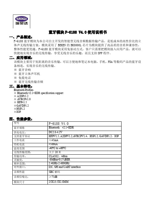
蓝牙模块F-6188 V4.0使用说明书一、产品概述:F-6188蓝牙模块为本公司自主开发的智能型无线音频数据传输产品,是低成本的高性价比的立体声无线传输方案,模块采用了BEKEN的BK8000L芯片为模块提供了高品质的音质和兼容性,整体性能更优越。
F-6188蓝牙模块采用免驱动方式,客户只需要把模块接入应用产品,就可以快捷地实现音乐的无线传输,享受无线音乐的乐趣,而且支持SPP程序。
二、应用领域:该模块主要用于短距离的音乐传输,可以方便地和笔记本电脑,手机,PDA等数码产品的蓝牙设备相连,实现音乐的无线传输。
※ 蓝牙音响※ 蓝牙立体声耳机※ 免提电话※ 蓝牙无线传输音频三、基本特性:Bluetooth Profiles※ Bluetooth v2.1+EDR specification support※ A2DPv1.2※A VRCPv1.0※HFPv1.5※GA VDP1.2※HSP1.2※IOP--------------------------------------------------------------------------------------------------------------------------------------------- 五、模块尺寸图:--------------------------------------------------------------------------------------------------------------------------------------------- 六、模块脚位定义图--------------------------------------------------------------------------------------------------------------------------------------------- 七、引脚功能说明:---------------------------------------------------------------------------------------------------------------------------------------------F-6188模块应用过程中,请注意避免功放、升压线路等干扰源对模块的影响,避免模块供电回路同大功率电路单元形成串联回路,以此来提高整机SNR九、注意事项:A .关于无线蓝牙的使用环境,无线信号包括蓝牙应用都受周围环境的影响很大,如树木、金属等障碍物会对无线信号有一定的吸收,从而在实际应用中,数据传输的距离 受一定的影响。
- 1、下载文档前请自行甄别文档内容的完整性,平台不提供额外的编辑、内容补充、找答案等附加服务。
- 2、"仅部分预览"的文档,不可在线预览部分如存在完整性等问题,可反馈申请退款(可完整预览的文档不适用该条件!)。
- 3、如文档侵犯您的权益,请联系客服反馈,我们会尽快为您处理(人工客服工作时间:9:00-18:30)。
HC-04RBluetooth data module specificationsBluetooth®V2.0With EDRTYPE:VER:Document Number:Release Date:(2013-01-01New)Autbosr:※Does if there are any new version,without prior notice.Features:Fully Qualified Bluetooth System Bluetooth V2.0+EDR Specification Compliant1.8V core,1.8to3.6V I/O Low Power ConsumptionExcellent Compatibility with Cellular Phones,PDAs,Digital Cameras,PMP......Minimum External ComponentsIntegrated1.8V RegulatorVarious interfaces:USB,UART,PIO and PCMBuilt-In Self-Test Reduces Production Test TimesRoHS CompliantWi-Fi coexistence supportedContentsBlock DiagranWIFI Application Block DiagranSpecificationPIN DescriptionPower Supply DiagramApplication circuitryUART InterfacePCM InterfacePackage DimensionsBLOCK DIAGRAMWIFI Application Block Diagran2-wireco-existenceTraditional3-wireco-existenceEnhanced3-wire(Packet Traffic Arbitration)co-existenceSpecificationGeneral SpecificationPeak current during cold boot50.7mA Peak Tx current Master42.8mAPeak Rx current Master35.1mAPeak Tx current Slave43.5mAPeak Rx current Slave39.4mAREG_IN,VDD_PIO,VDD_PADSHost Inter face(Regulator In)VDD_REG:2.2~3.6V(UART,PCM and PIO Inter face) VDD_RART:1.7~3.6V(Core and RF block)VDD_1.8V:1.7~1.9VUARTBaud Rate9600~3MClock Source26MHZ crystalCarrier Frequency2400MHZ to2483.5MHZ(USA,Europe) Rx.Sensitivity(BER<0.1%)-78dbmOutput Power-2dBmModulation Method GFSK,1Mbps,0.5BT GaussianMaximum Data Rate2M bpsMaximum number of active slaves7Built in Firmqare Up to HCIInter faces USB,PCM,UART,PIOs Operating temperature-30~+70CStorage temperature-40~+85CPower Supply DiagramTerminal 3.0V Power Supply 1.8V Power Supply1.8V NC 1.7to1.9VVcc 2.2to3.6V NC Application circuitryPower ConsumptionOperation Mode ConnectionType UART Rate(kbps)Average UnitPage scan-115.20.37ma Inquiry and page scan-115.20.68ma ACL No traffic Master115.2 6.46ma ACL With file transfer Master115.211.73ma ACL No traffic Slave115.213.90ma ACL With file transfer Slave115.217.19ma ACL No traffic Master921.6 6.49ma ACL With file transfer Master921.632.91ma ACL No traffic Slave921.613.87ma ACL With file transfer Slave921.630.59ma ACL40ms sniff Master38.4 1.59ma ACL1.28s sniff Master38.40.20ma SCO HV1Master38.434.00ma SCO HV3Master38.417.33ma SCO HV330ms sniff Slave38.417.00ma ACL40ms sniff Slave38.4 1.60ma ACL1.28s sniff Slave38.40.24ma Parked1.28s beacon Slave38.40.18ma SCO HV1Slave38.434.02ma SCO HV3Slave38.420.94ma SCO HV330ms sniff Slave38.416.80ma Stanidby Host connection-38.49ua Reset(RESETB low)--20uaPIN DescriptionPin Symbol Description1PIO6I/O Programmable input/output line 2PIO7I/O Programmable input/output line 3PIO8I/O Programmable input/output line 4PIO0I/O Programmable input/output line 5PIO1I/O Programmable input/output line 6PIO5I/O Programmable input/output line 7PIO4I/O Programmable input/output line8RESET Reset,iflow.Input debounced so must below for>Sms tocause a reset9PCM-SYNC I/O Synchronous data sync10PCM-OUT Synchronous data output11PCM-IN ISynchronous datainput12PCM-CLK I/O Synchronous data clock13VCC D.C Input Voltage for Internal Regulator(2.2~3.6V)141V8D.C Input Voltage for the operation of Core and RFblock(1.7~1.9V)15USB-DN USB data minus16USB-DP Usb data plus with selectable interal1.5K pull-up resistor 17UART-TX UART date output active high18UART-CTS UART clear to send active low19UART-RTS UART request to send active low20UART-RX UART date input active high21AIO0I/O Programmable input/output line22PIO3I/O Programmable input/output line23PIO2I/O Programmable input/output line24GND Ground25ANT I/O Antenna Port26GND GroundUART InterfaceFour signals are used to implement the UART functionUART_RX and UART_TX transfer data and UART_CTS and UART_RTS can be used to implement RS232hardware flow control where both are active low indicators.The interface consists of four-line connection as described in below:Signal name Driving source DescriptionUART_TX HC-04R module Data from HC-04R moduleUART_RX Host Data from HostUART_RTS HC-04R module Request t o send output of HC-04R moduleUART_CTS Host Clear to send input of HZ-208moduleUART SettingsBluetooth Module can handle UART baudrate from9.6kbps up to3Mbps.User can change data format the following selection using PSKEY.However,host shall communicate with default setting UART connection initiated at first time.Baud Rate=(PSKEY_UART_BAUD_RATE)/(0.004096)Property Possible ValuesBCSP-Specific Hardware Enable or DisableBaudrate Min9600Baud,Max3MFlow Control RTS/CTS or NoneData bit length8bitParity None,Odd or EvenNumber of Stop Bits1or2Property Possible ValuesBCSP-Specific Hardware EnableBaudrate115.2kbpsFlow Control NoneData bit length8bitParity EvenNumber of Stop Bits1Default Data FormatPCM InterfaceBluetooth module offers a bi-directional digital audio interface that routes directly into the basebandlayer and does not pass through the HCI protocol layer.It allows the data to be sent to and recevied from a SCO connectionThis interface consists of four signals:a clock(PCM_CLK),a data input(PCM_IN),a data output(PCM_OUT),and a frame-synchronization signal(PCM_SYNC)Bluetooth module interfaces directly to PCM audio devices including the following:-Qualcomm MSM3000series and MSM5000series CDMA baseband devices-OKI MSM7705four channel A-law and u-low CODEC-Motorola MC1454818-bit A-law and u-law CODEC-Motorola MC14548313-bit linear CODECPCM settingsBluetooth module can operate as the PCM interface master generating an output clock of 256kHz.When configured as PCM interface slave it can operate with input clock up to2048kHz.User can change data format the following selection using PSKEY.Property Possible ValuesMode Slave,MasterClock rateMaster mode:128,256,512kHzSlave mode:up to2048kHzClock formats Long Frame Sync,Short Frame SyncSample formats13or16-bit linear,8-bit u-law or A-lawDefault Data FormatProperty Possible ValuesMode MasterClock rate256kHzClock formats Long Frame SyncSample formats13-bit linearUART Bypass Mode-For devices that do not tri-state the UART bus,the UART bypass mode on bluetoothmodule can be used.-The default state of the module after reset is de-asserted is for the host UART bus to be connected to its UART.-In order to apply the UART bypass mode,a BCCMD command will be issued to themodule upon this,it will switch the bypass to PIO(4,5,6,7).Once the bypass mode has been invoked,it will enter the deep sleep state indefinitely.-In order to re-establish communication with the module,it must be reset so that thedefault configuration takes affect.-It is important for the host to ensure a clean bluetooth disconnection of any active links before the bypass mode is invoked.Therefore it is not possible to have active Bluetooth links while operating the bypass mode.Package DimensionsUnit:mm。