On- and Off-line Measurements
CRYSTA-Apex S系列CNC坐标测量机用户手册说明书

Coordinate Measuring MachinesBulletin No. 2024High-performance, low-price CNC CoordinateMeasuring Machine that meets global standardsThe CRYSTA-Apex S comes equipped with a temperature compensation system that guarantees the accuracy of measurement under temperature conditions of 16 to 26 °C. This system, based on permanently installed temperature sensors on each scale working together with sensors placed on the workpiece, monitors scale and workpiece temperatures and, monitors the temperature and, before outputting the measurement result to the controller, corrects it to the value that would be measured at 20 °C, taking into account the workpiece material expansion coefficient as well as the CMM's characteristics. The combined scale/workpiece temperature compensation scheme used on the CRYSTA-Apex S gives markedly superior results compared to systems that only compensate for scale temperature.Temperature sensor (for Scale)WorkpieceControllerTemperaturemeasuring and compensating deviceMPE accuracy specification limits at 20 ± 2 °CMPEE accuracy specification limits at 16 to 26 °C Measured length (mm)E r r o r (µm )The CRYSTA-Apex S is a high-accuracy CNC coordinate measuring machine that guarantees a maximum permissible error of MPE E = (1.7+3L/1000) μm [500/700/900 Series]. Let's compare the CRYSTA-Apex S with CMMs offering MPE E of approximately (2.5+4L/1000) μm. If, for example, the required tolerance on a dimension is ±0.02 mm, then the measuring machine uncertainty should be no more than one-fifth (ideally one-tenth) of that, i.e. 4μm. This means that with a general-purpose CMM, when the measured length exceeds 14.8"(375mm), machine uncertainty exceeds one-fifth of the dimension tolerance in this case. In contrast, as shown in the figure on the right, with the CRYSTA-Apex S the measurement uncertainty remains within one-fifth of the dimension tolerance up to 30.2"(766mm). The higher accuracy specification of the CRYSTA-Apex S therefore gives it more than double the 01002003004005006000.0020.0040.0060.008-0.002-0.004-0.006-0.008Measuring length (mm)CMM accuracy comparison700800900Accuracy envelope of the CRYSTA-Apex S Accuracy envelope of CMM with MPEE = (2.5+4 L/1000) µmM a x i m u m p e r m i s s i b l e e r r o r (m m )effective measuring range in terms of accuracy-guarantee capability in this case.High Accuracy in the 1.7 μm classTemperature Compensation System500 SeriesCNC Coordinate Measuring Machine CRCRYSTA-Apex S544The CRYSTA-Apex S Series offers a maximum drive speed of 519 mm/s and a maximumacceleration of 2,309 mm/s2, resulting in an increase of almost 100 mm in drive distance in onesecond, when compared with general-purpose CNC coordinate measuring machines (with amaximum speed of 430 mm/s and a maximum acceleration of 1,667 mm/s2).Furthermore, with a maximum measuring speed (i.e., the speed with which the stylus tracesover the workpiece) of 8 mm/s, the CRYSTA-Apex S produces measurements much morequickly than ordinary CMMs (with a maximum measuring speed of 5 mm/s). Combininghigh speed and high acceleration, the CRYSTA-Apex S dramatically reduces measuring time,with the difference between the CRYSTA-Apex S and ordinary CMMs only increasing as thenumber of measuring points increases, resulting in a significant reduction in measuring cost.As is the case with Mitutoyo’s conventional CMMs, various structures areemployed in the CRYSTA-Apex S in order to give the body higher rigidity. TheY-axis guide rail, which is integrated into one side of the granite surface plate,shows very little deterioration with use, and thus promises to maintain highaccuracy for a long time. The air bearings located on the bottom face, in additionto those at the front, rear, and upper surfaces of the slider unit of the X-axis,minimize vibration even during high-speed, high-acceleration movement, thusensuring stable linear motion.501001502002503003504004505000.100.20.30.40.50.60.70.8Reaches maximum speed in 0.253 secondsReaches maximumspeed in 0.225secondsTime (second)Effect of higher speed and acceleration on drive distanceCRYSTA-Apex S SeriesGeneral-purpose CMMMaximum speed: 430 mm/sMaximum acceleration: 1,667 mm/sDrivedistance(mm)High-speed, high-acceleration driveDesigned for high rigidity700 Series900 SeriesCRYSTA-Apex S776CRYSTA-Apex S9106 YSTA-Apex S SeriesIntegrated Y-Axis inGranite Tabletemperature environments 1 and 2.* When a mouse table is used: 33.5”(850mm)When a 2-monitor dedicated rack is used: 39.4”(1,000mm)CRYSTA-Apex S500 Series Dimensions unit: inch (mm)Installation floor spaceunit: inch (mm)When a 2-monitor dedicated rack is used: 39.4”(1,000mm)When a 2-monitor dedicated rack is used: 39.4”(1,000mm)F.LCRYSTA-Apex S900 Series Dimensions unit: Inch (mm) CRYSTA-Apex S700 Series Dimensions unit: Inch (mm)Installation floor space unit: Inch (mm) Installation floor space unit: Inch (mm)Group of options that enable various kinds ofGEOPAK (High-functionality general-purpose Measurement Program)This module is the heart of the MCOSMOS software system and is used to measure and analyze geometric elements. All the functions are provided by icons or pull-down menus, so even novices can promptly select desired functions. Its main features include easier viewing of measuring procedures and results such as real-time graphic display of measurement results and a function for direct call-up of elements from results graphics.MeasurLink ® STATMeasure Plus (Statistical-Processing and Process-Controlling Program)Performs various types of statistical computations using measurement results. In addition, by displaying a control diagram on a real-time basis, this program allows defects that may occur in the future (e.g., wearing or damaging of cutting tools) to be discovered early on. This program can also be linked to a higher-level network environment to build a central control system.CAT1000S(Freeform Surface Evaluation Program)Checks and compares the workpiece with the CAD data containing freeform surfaces and directly outputs the results in the form of CAD data in various formats. Software to directly convert from/to various types of CAD data is available as an option.CAT1000P (Programming from a CAD model)This module enables the user to use CAD data and on-screen simulation to create parts programs for making automated measurements (off-line teaching). This module allows the user to begin creating a parts program as soon as the design data has been finalized, shortening the entire process.SCANPAK (Contour Measurement Program)Software for scanning and evaluating workpiece contours (2D). Evaluates contour tolerance between measurement data and design data, and performs various types of element and inter-element calculations based on a desired range of measurement data specified by the user. SurfaceMeasure606(Non-Contact Laser Probe)Lightweight, high-performance, non-contact probe developed for CNC coordinate measuring machines. Simplified measurement has been achieved through automatic setting of appropriate laser intensity and camera sensitivity according to environment or material, providing a simpler and more comfortable laser scanning environment.MSURF (Non-Contact Laser Measurement and Evaluation Program)MSURF-S is used for obtaining measured point cloud data with the SurfaceMeasure (non-contact laser probe), while MSURF-I is used for comparing this data with the master model data, and for making dimensional measurements. Furthermore, MSURF-G for offline teaching allows the user to create a measurement macro even without the actual workpiece, improving the measuring machine's uptime.measurementsGEARPAK (Gear Evaluation Program)For evaluating the most types of involute gears.MPP-310Q (Scanning Probe)Probe that collects coordinate values (point cloud data) at high accuracy by moving at speeds of up to 120 mm/s while in contact with the workpiece. Because MPP-310Q can also be used with the rotary table (MRT320) for synchronous scanning, it is effective for measuring gears, blades, ball screws, cylindrical cams, etc.SP25M (Compact high-accuracy scanning probe)This is a compact, high-accuracy, multi-function scanning probe with a1"(25mm) outside diameter that makes scanning measurements, high-accuracy point measurements, and centripetal point measurements (optional function). The SP25M is used with the PH10MQ/10M auto probe head to provide a high degree of measurement freedom.MPP-10 (Probe for effective screw depth measurement)The probe that made it possible for a coordinate measuring machine to measure effective screw depthfor the first time in the world. The introduction of the auto probe changing system allows normal dimensional measurements as well as effective screw depth measurements to be made automatically.VISIONPAK(Vision Measurement Program)This program controls QVP and performs various computational analyses on captured images.Solid Model DeveloperThis program generates CAD data from data measured using MCOSMOS.MRT320QVP (Vision Probe)This probe automatically detects edges from image data of the workpiece magnified by a CCD camera. It is extremely useful for measuringmicrofabricated products that cannot be measured using a contact-type probe and soft objects that cannot be subjected to any measurement force. The QVP can also be used for measuring height based on autofocusing.UMAP-CMMThis head makes it possible to use an ultra-small diameter stylus (0.1- or 0.3-mm diameter). It can be installed on PH10MQ to measure the shape and dimensions of microfabricated products from multiple directions.NC-Auto measureThis program generates CAD data from NC data.Note: All information regarding our products, and in particular the illustrations, drawings, dimensional and performance data contained in this printed matter as well as other technical data are to be regarded as approximate average values. We therefore reserve the right to make changes to the corresponding designs. The stated standards, similar technical regulations, descriptions and illustrations of the products were valid at the time of printing. In addition, the latest applicable version of our General Trading Conditions will apply. Only quotations submitted by ourselves may be regarded as definitive.Mitutoyo products are subject to US Export Administration Regulations (EAR). Re-export or relocation of our products may require prior approval by an appropriate governing authority.Trademarks and RegistrationsDesignations used by companies to distinguish their products are often claimed as trademarks. In all instances where Mitutoyo America Corporation is aware of a claim, the product names appear in initial capital or all capital letters. The appropriate companies should be contacted for more complete trademark and registration information.© 2011 Mitutoyo America Corporation, Aurora IL5M – 0111-16 Printed in USA, May 2011Aurora, Illinois(Corporate Headquarters)Westford, Massachusetts Huntersville, North CarolinaMason, OhioPlymouth, MichiganCity of Industry, CaliforniaOne Number to Serve You Better 1-888-MITUTOYO (1-888-648-8869)。
ECE法规R54中英文对照C2类轮胎

E/ECE/324 Rev.1/Add.53/Rev.2E/ECE/TRANS/50516 April 2004AGREEMENT协议CONCERNING THE ADOPTION OF UNIFORM TECHNICAL PRESCRIPTIONS FOR WHEELED VEHICLES, EQUIPMENT AND PARTS WHICH CAN BE FITTEDAND/OR BE USED ON WHEELED VEHICLES AND THE CONDITIONS FOR RECIPROCAL RECOGNITION OF APPROVALS GRANTED ON THE BASIS OF THESE PRESCRIPTIONS _/关于适用于有轮车辆、设备和可安装在有轮车辆上使用的零件的统一技术规定的采用以及在这些规定基础上予以批准的互相认可条件_/(Revision 2, including the amendments which entered into force on 16 October 1995)(修订版2,包括从1995 年10 月16 日开始生效的修订容)Addendum 53: Regulation No. 54附录5 3: 54 号条例UNIFORM PROVISIONS CONCERNING THE APPROVAL OF PNEUMATIC TYRES FOR COMMERCIAL VEHICLES AND THEIR TRAILERS关于批准商用车及其拖车充气轮胎的统一规定UNITED NATIONS 联合国E/ECE/324 Rev.1/Add.53/Rev.2E/ECE/TRANS/505Regulation No. 54R e g ula t i on N o.5454号条例UNIFORM PROVISIONS CONCERNING THE APPROVAL OF PNEUMATIC TYRESFOR COMMERCIAL VEHICLES AND THEIR TRAILERS关于批准商用车及其拖车充气轮胎的统一规定CONTENTS目录Contents容1. SCOPE 适用围 (3)2. DEFINITIONS 定义 (3)3. MARKINGS 标志 (7)4. APPLICATION FOR APPROV AL 批准申请 (9)5. APPROV AL 批准 (10)6. SPECIFICATIONS 参数 (11)7. MODIFICATION AND EXTENSION OF APPROV AL OF A TYRE TYPE 轮胎系列批准的修正和延展138. CONFORMITY OF PRODUCTION 生产一致性 (14)9. PENALTIES FOR NON-CONFORMITY OF PRODUCTION 对于不符产品的处罚 (14)10. PRODUCTION DEFINITELY DISCONTINUED 勒令停产 (14)11. NAMES AND ADDRESSES OF TECHNICAL SERVICES RESPONSIBLE FOR CONDUCTING APPROV AL TESTS, AND OF ADMINISTRATIVE DEPARTMENTS 负责管理批准测试的技术服务机构和行政部门的名称及地址 (14)Annexes1 COMMUNICATION 信息表 (16)2 ARRANGEMENT OF APPROV AL MARK 批准标志的排列 (18)3 ARRANGEMENT OF TYRE MARKINGS 轮胎标志的排列 (19)4 LIST OF SYMBOLS OF LOAD-CAPACITY INDICES 负荷指数列表 (21)5 SIZE DESIGNATION AND DIMENSIONS 选取轮胎的规格与尺寸 (22)PART I 第1 部分EUROPEAN TYRES 欧洲轮胎 (22)PART II 第2 部分UNITED STATES TYRES 美国轮胎 (27)6 METHOD OF MEASURING PNEUMATIC TYRES 测量充气轮胎的方法 (32)7 PROCEDURE FOR LOAD/SPEED ENDURANCE TESTS 负荷/ 高速耐久性测试程序 (33)Appendix 1 附件7 –附录1 ENDURANCE-TEST PROGRAMME 耐久性测试程序 (34)Appendix 2 附件7 –附录2 RELATION BETWEEN THE PRESSURE INDEX AND THE UNITS OF PRESSURE 气压指数和气压单位之间的关系 (35)8 V ARIATION OF LOAD CAPACITY WITH SPEED COMMERCIAL VEHICLES TYRES 商用车负荷能力随速度变化表 (36)9 COMMUNICATION -Upgrade of service description for the purposes of retreading in accordance with Regulation No.109 通讯表按照第109号法规进行服务描述 (37)_________1. SCOPE 适用围This Regulation covers new pneumatic tyres designed primarily, but not only, for vehicles in categories M 2 , M 3 , N and O 3 and O 4 . / However, it does not apply to tyre types identified by speed category symbols corresponding to speeds below 80 km/h. 本条例适用于主要为M 2,M 3, N 和O 3以及O 4 车型设计,而不仅限于这些车型使用的新充气轮胎。
假肢与矫形器专业词汇英语

假肢与矫形器专业词汇(英语)abdomen anatomical retainer of the intestinesabdominal related to the abdomenabduct to move (a limb) away from the midline of the bodyabducted gait walking with the legs spread away from the midlinemuscleabductor abductingablatio mammae, mastectomy surgical removal of female breastabove elbow (A.E.) prosthesis prosthesis for transhumeral amputationabove the knee (A.K.) prosthesis prosthesis for transfemoral amputation - (AK)abutment counter piece, counter flare, neckacceleration getting continuously fasteracceleration phase sub-phase in the swing phase of gaitinpelvis, receiving the hip jointsocketacetabulum concaveacetone chemical thinner for laquers and paintsAchilles tendon tendon at distal end of calf muscleacrylic resin thermoplastic resin on acrylic basisacute rapid onset or short duration of a conditionadapter device coupling two different endsadduct to move (a limb) toward the midline of the bodyadductor adducting muscleadductor roll medial-proximally located roll oft soft tissue (TF-prosthetics) adhesion contact socket contact socket, type of suction socketadiposity being too large in abdominal and other circumferences, fat ADL's aids for daily livingadolescent juvenile - phase between childhood and adulthoodadultadolescent youngadult “grown up” - beyond adolescenceaetiology reason or factor causing a diseaseAFO ankle-foot-orthosisagonist muscle being active and result-oriented (opposite:antagaonist) aids for daily living (ADL) tools and devices etc.- modified for the disabledair splint orthoses containing an air chamber to customize fitAK (prosthesis) prosthesis after transfemoral amputationAK-socket above knee (transfemoral) socketalignment assembling O&P components referring to a reference system allergy reaction of the immune system against “foreign” matteralloy a mix of metals, changing the specific characteristics aluminum a light metalambulate / ambulation reciprocal walkingambulator a walking frame, supporting a patient's ambulation amputation surgical removal of a body partamputation surgery surgical act of removing a body segment (extremity) analgesia absence of, or insensitivity to pain sensationanalyse, analysis detailed research on components of a wholeanamnesis background of a diseaseanatomical landmarks (bony) prominences, points of importance in O&Panatomy descriptive or functional explanation of the body properties angularity in the shape of an angleangulus sub-pubicus angle of the pubic ramus, important in IC-socketsjointankle tibio-tarsalankle block connector between prosthetic foot and shinankle joint (talus joint) joint connecting foot and shankankle-foot orthosis (AFO) orthosis with functional impact on ankle and footankylosing to unite or stiffen by ankylosisankylosis immobility, posttraumatic fusion of a jointantagonist muscle opposing agonist action, often controllinganterior in front of, the foremostanteversion to bring (a limb) forward, opposite of retroversion anthropometry taking measurements of the human bodyanti… againstanvil block of iron, surface used in forging metalA-P or a-p antero-posterior, from front to backapex top or summit, the highest point, the peakappliance an instrument, O&P: a prosthesis or orthosis, technical aid application making work or connecting to…learning a professionapprentice somebodyapprentice student learning a profession or craft in a structured approach apprentice student learning a profession or craft in a structured approach apprenticeship (course) training course for vocational educationappropriate best (compromise-) solution for a given problem Appropriate Technology technology appropriate (e.g. for the Third World)arch support shell shell-like custom molded medical shoe insertarteries blood vessels transporting oxygenated blood to the periphery arthritis acute or chronic joint inflammationarthrodesis blocking a joint through surgical procedurearthroplasty reconstruction of a joint through surgical procedure arthrosis, osteoarthritis joint disease - degenerating cartilage and joint surfaceGelenkarticulation Articulatio,aseptic not caused by bacterial infectionASIS / A.S.I.S anterior superior iliac spineassessment evaluation, obtaining information (about a condition) athetosis condition of slow withering movementsathletic arch support custom molded medical shoe insert for the athleteatrophy shrinkage, wastage of biological tissueautonomic nervous system independent nerve tissue, not under voluntary controlaxial rotator joint for socket rotation around the vertical axisback posterior component of the trunkbalance condition of keeping the body stabilized in a desired positionball bearing bearing cage containing rollers, making/keeping axes rotatable ball joint (universal joint) tri-axial jointband, strap, cuff suspension aid (small corset)bandages elastic wrapping, light brace, adhesive wrapping etc.bandaging act of applying bandages, tapingbands m-l connection between orthotic side bars (calf band etc.)bars, side-bars uprights, vertical struts in an orthosisbearing, ball bearing bearing cage containing rollers, making/keeping axes rotatable bed sore pressure/shear related skin trauma of bed-bound individuals below elbow amputation (BE-) forearmamputation (below the elbow joint, transradial, transulnar) below elbow, lower arm arm below the elbow jointbelt suspension component, also light abdominal bandagebench workstation,worktablebench alignment static alignment of prosthetic/orthotic componentsbending providing a shape or contour to sidebars, bands etc.bending iron set of two contouring tools for metal bar bendingbending moment the force or torque bending an objectbending, contouring providing a shape or contour to sidebars, bands etc.BE-prosthesis prosthesis after amputation below the elbow jointbevel to brake an edgebig toe halluxbilateral twosided, double..., relating to “both sides”bio-engineering science of engineering related to living structuresbio-feedback internal autoresponse to a biological eventbiological age the "natural age" - dependent on how a person presentsbiology science related to living structuresbio-mechanics science combining biology and mechanicsbipivotal joint joint with two axesBi-scapular abduction bringing both shoulders forward simultaneously (prosthetic control motion)BK below the kneeBK-prosthesis prosthesis after amputation below the kneeBK-socket below the knee socketblister forming vacuum molding plastic sheet material in a frameblock heels wide basis heelsbody the total appearance of a biological beingbody jacket US-American term for symmetrical spinal orthosesbody powered operated by human power (as opposed to outside energy) bolts machine screw and similarbonding agent connective glue, cement etc.bone single part of the skeletal systembone loss syndrome reduction of bony massbone spur a protrusion of bone or fragment of bonebonification, calcification change into bony tissuebony bridge surgical bony fusion between e.g. tibia and fibulabony landmark anatomically protruding bony surfaces (as the fibula head) bony lock (ischial containment) m-l tight locking design in ischial containment sockets bordering providing a smooth trim line or brimbordering, trimming providing a well-rounded trim line or smooth brimBoston Brace spinal orthosis developed in Boston, USA (scoliosis, kyphosis treatment)bouncy mechanism flexion device for limited flexion in prosthetic kneesbow leg genu varum, o-shaped legs, enlarged distance between knees brace, splint, caliper supportive device, old-fashioned for “orthosis”brain, cerebrum main switch board of the central nervous systembrazing heat supported metal solderingbrazing tool, soldering iron tool for heat supported metal solderingbrim proximal socket area, casting tool / templatebrooch / hook hooks holding a lace, closure of shoes etc.buffing creating a shiny surface finishbuild-up (of a material) location of added plaster in modifications of plaster castsburn heat related injurybursa anatomic padding cavity containing liquidby-law (USA: bill) lawCAD CAM Computer Aided Design, Computer Aided Manufacture cadence rhythm of walkingcalcaneus heelbonecalculation doing mathematical operationscalf band m-l connection between side bars (KAFO)calf corset enclosure of calf and shin (in an orthosis)calf muscle, triceps surae plantar flexor of the foot, muscle in the lower legcaliper measuring tool, precision instrumentcaliper, brace, splint old fashioned term for joint stabilizing lower limb orthoses Canadian Hip Disarticulation Pr. external shell prosthesis for hip disarticulationscane walkingstickcap band finishing element of trim lines, brims of corsetscarbon fiber structural reinforcement in plastic compositescardanic two axes, aligned in 90 degrees toward each othercardio-vascular related to heart and blood circulationcarve shaping by taking material off (chipping off, sanding off)cast positive (plaster or similar) moldcast modification functional changing of the shape of a castcast removal removal of plaster bandage from a poured plaster castcast taking act of taking a plaster- or similar impressioncasters freely moving front wheels at a wheel chaircasting and measurement taking getting 3-dimensional body impressions and measurements casting procedures technique of getting 3-dimensional body impressions caudal direction, toward distal end of the vertebral column (tail)c-clamp clamping tool (woodwork)CDH congenital dislocation of the hipcell (biological and technical) smallest living unit; hollow technical unitcellular made up from cellscelluloid one of the first plastic materials availablecement, glue bonding agentcenter of gravity (COG) mathematic-physical mass concentration in one point center of mass calculated concentration of mass (in bio-mechanics) center of mass (COM) mathematic-physical mass concentration in one point centrode graph for the path of the instantaneous centers of rotation cerebral related to the cerebrum, braincerebral palsy loss of neural muscle control by congenital brain damage cerebral paresis dysfunction of muscle tissue related to cerebral trauma cerebro vascular accident vascular bloodclotting in a part of the brainbraincerebrum thecerebrum / cerebral brain / related to the braincervical related to the neckcervical collar (cervical brace) orthosis for the neck (after whiplash syndrome)cervical spine most proximal segment of the spinal columnchairback brace posterior semi-shell trunk orthosischamfer to thin out the edges of a materialCharcot joint rapid progressive degeneration of a joint (foot)check-, or diagnostic socket transparent or translucent socket for diagnosis of fit chiropedist (Canada) medical doctor specialized in foot careChopart amputation tarsal (partial) foot amputation at the Chopart joint line Chopart joint tarsal joint line of several bones in the footchronic long term (disease; opposite of acute)circumduction semi-circular (mowing) forward swing of a leg circumference the measurment around a physical bodyclam shell design longitudinally split socket or shellclosure mechanism used to closeclub foot, talipes varus pes equino varus, a congenital (or acquired) foot deformity CNC Computer Numeric Controlled design and manufacturing CO cervical orthosis, orthosis for neck immobilizationCO - CP - CPO Certified ... Orthotist..Prosthetist..Prosthetist/Orthotist coating surface cover (as plasticising metal surfaces)coccyx Anatomy: the “tailbone”coefficient of friction number determining forces between sliding surfacescollar cervical orthosis, orthosis for neck immobilization collateral ligaments ligaments bridging the side of jointscompatible fitting to each othercompliance measure of willingness to follow a therapeutic ordercomponents single parts of a whole, construction parts, pre-fab partscomposite reinforced plastic component, matrix and fillercompound result of a chemical binding processcompression panty hose orthotic garment to treat varicosisconcave inwardly shaped, hollow (opposite of convex)condyle massive rounded end of bone, basis for forming a joint surfacewithborncongenital beingconstant friction continuous application of a braking forcecontact cushion distal contact padding in prosthetic socketcontact measuring measuring while touching the object measuredcontact pad contact cushion (prosthetics)continuous passive motion (CPM) keeping a joint mobile through passive motion in motorized device contour (the) the outer perimeter of a bodycontour (to) creating a shape by forming, bendingcontour drawing draft of the outer perimeter of a bodycontracture condition of motion limitation in jointsconvex outwardly shaped, bulged (opposite of concave)cork bark of a tree, natural cellular leight weight materialcoronal plane frontal planecorrection, rectification modification (of shapes, designs etc.) in order to improvecorrosion deterioration of materials by chemical influence (as oxdation)corset therapeutic circular enclosement of body segmentscorset, fabric corset lumbar brace made from textile materialcountersinking taking the edge off a drilled hole, creating circular concavitycoupler a connective devicecoxitis/coxarthritis inflammation of the hip jointCPM, continuous passive motion keeping a joint mobile through passive motion in motorized device CPO Certified Prosthetist / Orthotistcraft & trade European (German) vocational structuring systemcranial relating to the headcrossline filing using a handheld file in a 90 degrees offset directioncruciates, cruciate ligaments crossed ligaments at the knee centerCRW Community based Rehabilitation Worker (WHO Geneva)CT, computer tomography a method to take X-rays in "slices"Orthosis CTLSO Cervico-Thoraco-Lumbo-SacralOrthosisCTO Cervico-Thoracocuff, band, strap suspension aid (small corset)cup, connection cup socket connector in prostheticscure (med.) medical therapeutic measurecure (techn.) to set, hardencushion, pad upholstering device, providing soft surfacecustom made made to measurements as a single unitdeceleration to become continuously slowerdeceleration phase sub-phase in the swing phase of human gaitdecree, directive, regulation text in the lawbooks or regulation with law-like characterdeficiency lack of necessary function or ability by physical impairmentdeflector plate a leaf spring design in prosthetic feet, energy return devicedeformity malformation of form, may be influencing functiondegeneration biological wear and tearDelrin a plastic material, used as a flexible, energy returning keeldensity foaming hard foam block on a socket as a connector to componentsdeposit (biological or pathological) storage mechanism, sedimentdermatitis skin disease, infection of the skinderotating orthosis (scoliosis) orthosis for derotation - one of the priciples of scoliosis treatment design construction, functional lay-out and planningdexterity, manual skill skill of creating by hand, craftsman skilldiabetes mellitus carbohydrate metabolism disorder (frequent amputation reason) diabetic gangrene death of tissue caused by diabetesdiagnosis searching and finding a cause and details of diseasediaphysis shaft of a long bonedimension seize as measureddimensional stability keeping the dimensionsdiplegia paralysis, affecting both sides of the bodydirect socket technique manufacture of a prosthetic socket directly on the amputee's limb directive information or order on how to …..directive, regulation, decree text in the lawbooks or regulation with law-like characterdisability handicap, functional loss of abilitydisabled person a person with a disability, handicapdisabled, handicapped handicapped, having a functional loss of ability"amputation"directly through a joint linedisarticulation thedisc, intervertebral disc intervertebral cartilaginous cushioning elementdislocation joint injury resulting in complete discontiuity of joint surfaces dislocation overstretching or rupture of ligaments, also in combination with fracture doff US-colloquial: do - off = take offdoffing a prosthesis taking off a prosthesiscontrollingdominant leading,don US-colloquial: do - on = put ondonning a prosthesis putting on a prosthesisdonning aid aid to don a prosthesis as pull sock, stockinette, silk tie etc.dorsal related to the dorsum = back, posteriorly locateddorsiflexion lifting the forefoot, correct would be “dorsal extension”, lift of footdraft first drawing of a new ideadrawer effect a-p instability of the knee caused by slack cruciatesdrill (to) to machine a holeDS(L)T Direct Socket (Lamination) TechniqueDUCHENNE's disease severe progressive form of muscular dystrophyDUCHENNE's sign trunk bends lateral toward stance leg during stance phaseDUPUYTREN’sche Kontraktur fibrosis, flexion contracture of fingers into palmstiffnessdurometer hardness,duroplastic resin synthetic resin, not thermoplastic after initial curingdystrophy pathologic loss of muscle massCommunityEC Europeanedema, oedema swelling, high concentration of fluids in the soft tissueelastic capable of recovering form and shape after deformation elastic anklet ankle foot orthosiselastic bandage, ACE-bandage stretchable, expandable bandageelastic knee sleeve knee supporting soft orthosis, tt-prosthetic suspensionelbow splint old-fashioned term for: elbow orthosiselectrical stimulation neuromuscular stimulation by electric impulses electromyography recording of electrical activity of a muscleembedding enclosing, encapsulating, (German: socket retainer function) embossing manual shaping of sheet metal by special hammerEMG recording of electrical activity of a muscleendo-skeletal pylon type prosthetic components covered by external cover energy consumption use of energy in physical activitiesenergy expenditure spending of energy in physical activitiesenergy return energy output, achieved by spring-like design in O&PorthosisEO elbowepicondylitis stress related inflammation of the elbow, (tennis)epiphysis dist./prox. End of a bone, zone of longitudinal growth equilibrium keeping of balanceequinovalgus combined drop foot and valgus deformityequinovarus combined drop foot and varus deformityeversion rotation of hand or foot around long axis of the limbeversion turning foot outward and up (opposite of inversion)EWHO elbow wrist hand orthosisexamination, assessment evaluation, obtaining information (about a condition)exo-skeletal prosthetics: external structural components (opposite: modular) extension straightening motion of a jointextension assist strap or other means assisting joint extensionextension moment force (torque) causing extension (straightening) of joints extension stop bumper or other means of extension limitationextensor muscle causing extensionexternal related to the outside (opposite: internal)external fixation outside orthotic fixation (of a fracture or a surgical result) extremity upper or lower extremities: arms or legsfabric corset textile orthosis for the abdomen or trunkfabrication the procedure of mechanically creating a devicefatality mortality, death ratefatigue (material) time-dependent alteration of typical material propertiesfatigue (muscles) time-dependent slow down of muscle actionFederal Trade Association German professional trade associationfeedback return of informationfelt material made up from compressed, interwoven hair or fiber female the woman species in a creature (opposite: male)femoral channel dorso-lateral convex channel in a prosthetic socketfemoral condyles the distal ends (close to the knee joint) of the femurfemur the thigh boneFES functional electrical stimulationfibre glass (fiber glass) glass reinforcement component in compositesfibula calfbone, the lesser of two bones in the calffibular head the proximal thicker portion of the fibulafit compatibility between patient and device in function/comfortflab abundance of soft tissueflaccid paralysis, paresis non-spastic paralysis, loss of voluntary muscle innervationflare even anatomical surface (as the tibial flare)flat evenflat foot foot deformity, loss of medial-longitudinal arch heightflatfoot, talipes planus foot deformity, loss of any medial-longitudinal arch heightflexion joint motion, buckling or bending a jointflexion assist device assisting (joint) flexionflexion moment force (torque) causing flexionflexor muscle creating a flexion motionfloor reaction orthosis orthosis utilizing floor reaction forces for patient stabilizationFO (either) finger orthosis (or) foot orthosisfoam a cellular resin (polyurethane foam hard or soft)foaming act of manual creation of a prosthetic foam connectorchildfoetus unbornfollow-up continuous control and maintenance, aftertreatmentfoot cradel anatomically adapted plantar foot supportfoot deformity misalignment (functional misshape) of the footfoot flat stance phase: sole of the foot getting in complete ground contact foot slap stance phase: uncontrolled quick foot flat motionforce cause or reason for acceleration, deceleration, movementforging non-chipping iron shaping process under the influence of heat fracture traumatic breaking of a boneframe the outer supportive, stiffening elementframe socket the outer supportive, stiff element as a retainer for a flexible socket freehand drawing, draft manual first draft or drawingcounter-acting sliding movement, "rubbing"friction forcefrontal plane, coronal plane reference plane as seen from the frontfulcrum center of a single axis joint, center of rotationfully synthetical man-made (material)functional component i.e. joints etc. (as opposed to structural components)functional level degree of function a disabled patient still achievesfunctional needs component need to satisfy specific needsfundamental of basic importanceambulationgait walking,gait analysis research of gait patterns and time-related specificsgait deviation pathological changes in normal walking patternsgait pattern physiological or pathological walking characteristicsgait trainer somebody teaching how to walkgait training lessons in learning how to walkgalvanization surface protection of metalsgangrene local death of soft tissue due to lack of blood supply gastrocnemii, “gastrocs” double-headed calf musclegauge measuring instrument (measures width / thickness)gear train joint joint components, forcing each other trough toggled connection gel man-made or natural material, consistency similar to gelantine genu kneegenu recurvatum hyper-extended knee joint (frequently seen in poliomyelitis) genu valgum/knock knee knock knees, knees frequently touching each other medially genu varum/bowleg bow legs, knee distance too large (opposite of genu valgum) geometric locking locking systematic of polycentric knee jointsgeometrical stance control locking systematic for the provision of stance stabilitygeriatric elderly, old, aged,glue, cement bonding agentgoniometer instrument (tool) for measuring anglesgrease fat, as lubricant or tissuegrid particle size indication in abrassive materialsgrind surface modification by abrasion, sanding etc.ground reaction force force directed from the ground toward the body Haemo.., haema... related to the bloodhallux, halluces big toeHalo brace cranial/cervical orthoses, ring fixed at proximal cranium hamstrings popliteal tendons, insertion of flexor muscleshand splint old fashioned for hand orthosishard and soft foaming technique of using hard and soft PU-foams in combinationhd extra sturdy version of…..disarticulationHD hipHDPE HighPolyethyleneDensityHD-socket pelvic socket of the hip disarticulation prosthesisheavy metals a specific group of metals (heavy in weight)heel clamp prosthesis a partial foot prosthesis, suspension by a posterior "clamp" heel cup foot orthosis, Berkely cupheel off / heel rise moment in stance phase when the heel risesheel spur bony protrusion at the distal-medial aspect of the calcaneus heel strike moment in stance phase when the heel touches the ground heel wedge heel bumper in foot or length compensation, absorbs shockHelfet’s heel cup foot orthosis, similar Berkely cupremoving the distal half of the bodysurgery,hemicorporectomy amputationhemipelvectomy amputation surgery removing one half of the pelvis hemipelvectomy-prosthesis artificial leg after hemipelvectomyhemiplegia paralysis of one half side of the bodyheredetary congenital by transmission from parent to offspringhernia subcutaneous protrusion of intestinshindfoot posterior 1/3 of the foot (heel and tarsus)hinge simple joint, single axiship dysplasia pathological development of hip socket leading to dislocation hip hiking exaggerated movement (lifting) of the hip joint in gaithip joint, articulatio coxae proximal joint of the leg, leg-pelvis jointhip positioning orthoses a brace controlling functional alignment of the hip jointhip socket concave component of the hip jointhip spica cast applied to pelvis and legHKAFO Hip-Knee-Ankle-Foot-OrthosisHO (either) Hand Orthosis (or) Hip Orthosis (!!)hobby-handicraft hobbyists work also meaning: non-professional resulthook and eyelet closure closure of textile fabric corsetshook and pile closure Closure material with interlocking surfaces (e.g. Velcro)hook and pile, Velcro self-adhesive strap materialhorizontal plane reference plane as seen from the tophosiery, medical hosiery medical compression hosiery (phlebology)humerus bone in the upper armhybrid something having properties of at least two different resources hydraulic joint control cylinder/piston device controlling prosthetic joint motion hyper… more of somethinghyperextension over-stretching (of a joint)hyperextension orthosis a spinal brace serving for reclination of the thoracic spinegrowthhyperplasia increasedhyper-reflexia pathologically exaggerated reflexeshypertonia elevated blood pressurehypertonicity increased muscle tone or muscle tensionhypertrophy growth of tissue by enlargement of cellshypo… less of somethinghypoplasia biological structure significantly diminished in sizehypotonia low blood pressurehypotonicity loss of muscle tone (or tension)ContainmentIC IschialICRC International Committee of the Red CrossICRC Ischial and ramus containmentIC-socket ischial containment socketidiopathic scoliosis adolescent scoliosis without a known causeilium, os ilium the medial or lateral "wing-shaped" bone in the pelvis。
USP34 645 水的电导率(中英文)

USP34 <645> 水的电导率(中英文)<645> WATER CONDUCTIVITY 水的电导率Electrical conductivity in water is a measure of the ion-facilitated electron flow through it. Water molecules dissociate into ions as a function of pH and temperature and result in a very predictable conductivity.水的电导能力是对水中离子化电子的一种测量。
离解为离子的水分子是pH值、温度的函数,它导致可预期的电导率。
Some gases, most notably carbon dioxide, readily dissolve in water and interact to form ions, which predictably affect conductivity as well as pH. For the purpose of this discussion, these ions and their resulting conductivity can be considered intrinsic to the water.一些气体,特别是二氧化碳,容易溶于水中并产生反应形成离子,对电导率产生影响。
在本讨论中,这些离子和其对电导率的影响结果可以认为是水的内在本质。
Water conductivity is also affected by the presence of extraneous ions. The extraneous ions used in modeling the conductivity specifications described below are the chloride and sodium ions. The conductivity of the ubiquitous chloride ion (at the theoretical endpoint concentration of 0.47 ppm when it was a required attribute test in USPXXII and earlier revisions) and the ammonium ion (at the limit of 0.3 ppm) represent a major portion of the allowed water impurity level. A balancing quantity of cations, suchas sodium ions, is included in this allowed impurity level to maintain electroneutrality. Extraneous ions such as these may have significant impact on the water's chemical purity and suitability for use in pharmaceutical applications. The procedure in the section Bulk Water is specified for measuring the conductivity of waters such as Purified Water, Water for Injection, Water for Hemodialysis, and the condensate of Pure Steam. The procedure in the section Sterile Water is specified for measuring the conductivity of waters such as Sterile Purified Water, Sterile Water for Injection, Sterile Water for Inhalation, and Sterile Water for Irrigation.水的电导率还受到外来离子的影响,下面所述的包括在电导率质量标准中的外来离子包括氯离子和钠离子。
High-efficiency
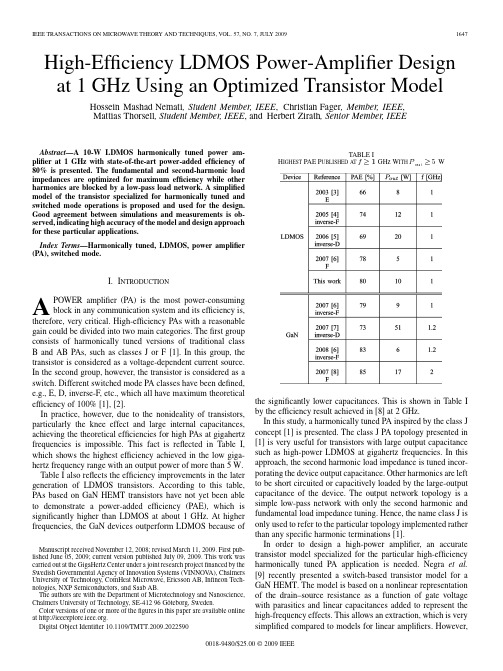
High-Efficiency LDMOS Power-Amplifier Design at1GHz Using an Optimized Transistor Model Hossein Mashad Nemati,Student Member,IEEE,Christian Fager,Member,IEEE,Mattias Thorsell,Student Member,IEEE,and Herbert Zirath,Senior Member,IEEEAbstract—A10-W LDMOS harmonically tuned power am-plifier at1GHz with state-of-the-art power-added efficiency of 80%is presented.The fundamental and second-harmonic load impedances are optimized for maximum efficiency while other harmonics are blocked by a low-pass load network.A simplified model of the transistor specialized for harmonically tuned and switched mode operations is proposed and used for the design. Good agreement between simulations and measurements is ob-served,indicating high accuracy of the model and design approach for these particular applications.Index Terms—Harmonically tuned,LDMOS,power amplifier (PA),switched mode.I.I NTRODUCTIONA POWER amplifier(PA)is the most power-consumingblock in any communication system and its efficiency is, therefore,very critical.High-efficiency PAs with a reasonable gain could be divided into two main categories.Thefirst group consists of harmonically tuned versions of traditional class B and AB PAs,such as classes J or F[1].In this group,the transistor is considered as a voltage-dependent current source. In the second group,however,the transistor is considered as a switch.Different switched mode PA classes have been defined, e.g.,E,D,inverse-F,etc.,which all have maximum theoretical efficiency of100%[1],[2].In practice,however,due to the nonideality of transistors, particularly the knee effect and large internal capacitances, achieving the theoretical efficiencies for high PAs at gigahertz frequencies is impossible.This fact is reflected in Table I, which shows the highest efficiency achieved in the low giga-hertz frequency range with an output power of more than5W. Table I also reflects the efficiency improvements in the later generation of LDMOS transistors.According to this table, PAs based on GaN HEMT transistors have not yet been able to demonstrate a power-added efficiency(PAE),which is significantly higher than LDMOS at about1GHz.At higher frequencies,the GaN devices outperform LDMOS because ofManuscript received November12,2008;revised March11,2009.First pub-lished June05,2009;current version published July09,2009.This work was carried out at the GigaHertz Center under a joint research projectfinanced by the Swedish Governmental Agency of Innovation Systems(VINNOV A),Chalmers University of Technology,ComHeat Microwave,Ericsson AB,Infineon Tech-nologies,NXP Semiconductors,and Saab AB.The authors are with the Department of Microtechnology and Nanoscience, Chalmers University of Technology,SE-41296Göteborg,Sweden.Color versions of one or more of thefigures in this paper are available online at .Digital Object Identifier10.1109/TMTT.2009.2022590TABLE IH IGHEST PAE P UBLISHED AT f 1GHz W ITH P 5Wthe significantly lower capacitances.This is shown in Table I by the efficiency result achieved in[8]at2GHz.In this study,a harmonically tuned PA inspired by the class J concept[1]is presented.The class J PA topology presented in [1]is very useful for transistors with large output capacitance such as high-power LDMOS at gigahertz frequencies.In this approach,the second harmonic load impedance is tuned incor-porating the device output capacitance.Other harmonics are left to be short circuited or capacitively loaded by the large-output capacitance of the device.The output network topology is a simple low-pass network with only the second harmonic and fundamental load impedance tuning.Hence,the name class J is only used to refer to the particular topology implemented rather than any specific harmonic terminations[1].In order to design a high-power amplifier,an accurate transistor model specialized for the particular high-efficiency harmonically tuned PA application is needed.Negra et al.[9]recently presented a switch-based transistor model for a GaN HEMT.The model is based on a nonlinear representation of the drain–source resistance as a function of gate voltage with parasitics and linear capacitances added to represent the high-frequency effects.This allows an extraction,which is very simplified compared to models for linear amplifiers.However,0018-9480/$25.00©2009IEEEFig.1.Idealized transistor load-line trajectories illustrating the difference be-tween traditional class AB and high-efficiency PAs.The dotted line represents the short transition time between on-and off-state in high-efficiency amplifiers. due to the simplifications made,the model is not able to predict the high-frequency behavior in a PA very well,especially when the supply voltage and frequency are detuned from their original design values.In this paper,a simplified transistor model optimized for harmonically tuned PAs such as F and J(first category),and switched-mode PAs(second category)is extracted and used in the design.The model is based on simplified expressions for the nonlinear currents and capacitances where the agreement in high-efficiency areas has been specifically stressed.The model allows the intrinsic waveforms to be studied in the PA design, and therefore,allows a careful investigation of the transistor operation.II.T RANSISTOR M ODELING FOR H IGH E FFICIENCY PAs This section describes the transistor characterization and modeling procedure used for design of the high-efficiency PA presented.The need for a model specialized for high-efficiency harmoni-cally tuned PA designs relates to the fact that the transistor mode of operation is fundamentally different compared to traditional linear class AB type of amplifiers.This is illustrated in Fig.1, which compares the load line of a traditional class AB PA with the one in a high-efficiency PA.Commercially available transistor models are normally opti-mized for class-AB operation,which means that the accuracy in the high-efficiency load-line region,shown in Fig.1,is compro-mised.A consequence is also that commercially implemented models often suffer from convergence problems when used for switched-mode PA design[9].Moreover,in order to eliminate the parasitics associated with packaged transistors,a bare-die approach is used in this study. This approach was also used in[8]where the transistor chip was wire bonded directly to the circuit.The reference plane of the transistor model is,therefore,set to the transistor chip surface.To facilitate a repeatable method for characterization of the bare-die devices to the chip surface reference plane,a package-based technique is developed.A.Bare-Die Transistor Characterization MethodThe bare-die characterization procedure may be summarized as follows.First,the transistor chip is mounted in a high-perfor-mance liquid-crystal polymer package(JT973C,RJRPolymers Fig.2.Model for the package used for the transistorcharacterization.Fig.3.(a)Short and open package standards.(b)Transistor die mounted in package during characterization.Inc.,Oakland,CA).The package is then placed in a high-power testfixture(Inter-Continental Microwave,Chandler,AZ)during the characterization.The testfixture includes thru-reflect-line (TRL)calibration standards,which brings the reference plane to the tabs of the package.Finally,a model of the package is developed and used to deembed the influence of the package from the measurements.Thisfinally brings the reference plane of the measurements to the bond wires of the transistor die.This procedure is similar to the one presented in[10],but uses mea-surements instead of3-D electromagnetic simulations tofind the package model parameters.Fig.2shows the topology used to model the package.The package model parameters are ex-tracted with the help of three package standards:thru,short,and open.The thru and short standards are realized by adding bond wires between the package input–output and input–ground,re-spectively[see Fig.3(a)].Fig.3(b)shows a10-W NXP LDMOS transistor die mounted in the package.The product number for an unmatched packaged version of this transistor die is BLF6G21-10.This is also the same transistor used in the PA design.Once mounted according to the procedure above,dc andbias-dependent-parameter measurements are used to characterize the bare-die device. Fig.4shows measured dc I/V characteristics.Squaremarkers are used to indicate the measurement points in the on-and off-states,which are considered most critical in terms of modeling for high-efficiency PAs according to Fig.1.Note that the thermal effects are not dominant in these states,and therefore,static measurements are consideredsufficient.-parameter measurements are performed at each of the points in Fig.4and forms the basis for the extraction of the new transistor model.NEMATI et al.:HIGH-EFFICIENCY LDMOS PA DESIGN AT 1GHz1649Fig.4.Measured transistor dc characteristics (2).Points critical for high-ef-ficiency PA operation are indicated with square markers ().rge-signal transistor model topology.The intrinsic bias-dependent part of the model is enclosed by the dashed rectangle.B.Transistor ModelingThe model developed in this section is based on expressionsthat focus on accurately predicting the on and off areas of the transistor characteristics.1)Model Topology:The model topology used is depicted in Fig.5.Despite its relative simplicity,it has been found to accurately reproducemeasured -parameters tofrequencies 6GHz within all bias regions of interest.A multibias optimizer-based extraction technique is then em-ployed to extract the extrinsic parameters of the model [11].This method has previously proven to give reliable and accu-rate results with LDMOS devices [12].The resulting values of the extrinsic parameters are given in Fig.5.Notethatdescribes what is referred as the drain–sourceon-resistance,which can also be identified from the slope of the I/Vcurve in Fig.6.The extrinsic parameters are then fixed and the intrinsic pa-rameters are extracted versus bias using a similar optimization technique minimizing the difference between measured andmodeled -parameters.The results are used for the large-signal modeling.2)Nonlinear Drain Current:The model equation used to approximate the intrinsic nonlinear current source in Fig.5hasFig. parison between measured (markers)and modeled (lines)drain–source current in the on-state region.been developed having the high-efficiency load line of Fig.1in mind.This means that the model accuracy in the on region,i.e.,where drain–source voltage is low and the drain current is high,is of main consideration.Nevertheless,since the transistor is operated part of the time in other regions,it is still important to base the model on equations that give physically reasonable results also in the intermediate transition regions.The modelused in this work is,therefore,based onthemodel equa-tions presented in [12].This model has also been successfully used by others for LDMOS and GaN devices [13],[14]and is proven to predict practical device characteristics with a reason-able number of model parameters.The model equation in this model is in its basic form given by the followingexpression:(1)where is an effective gate–sourcevoltage used both to describe exponential characteristics in the sub-threshold re-gion,and saturation of the drain current athigh[12].In terms of modeling the on region,the characteristics aremainly determined bythefunction andthe parameter.Theused in the denominator ofthe function was introduced in [15]to model the relatively smooth resistive to saturation transition observed in LDMOS devices.In this study,we have found that the agreement in the on region can be fur-ther improved by replacing the tanh function with the following arctan-based modelexpression:(2)where the scalingfactor has been used for normalization purposes.Fig.6shows measured and modeleddccharacteris-tics in the knee region when the new model is used.As shown,the model gives a good agreement with the measurements.It should be noted that a simple electrothermal self-heating model has been used to take the thermal effects into consideration [12].The nonlinear current model parameters,including the thermal effects,are extracted using a manual fitting procedurewhere static dc and small-signal parameters(and )are1650IEEE TRANSACTIONS ON MICROWA VE THEORY AND TECHNIQUES,VOL.57,NO.7,JULY 2009TABLE IIE XTRACTED IC URRENT S OURCE M ODEL P ARAMETERS C ORRESPONDING TO THE M ODEL IN(2)parison between measured (markers)and modeled (lines)capacitance values versus bias.Thin square markers ()are inserted in the plots to indicate operating voltages corresponding to the transistor on and off regions.fitted to measurements in the on region.The complete set of model parameters are summarized in Table II.3)Nonlinear Capacitances:Simplified models are derived for the nonlinear capacitances following the same procedure as for the current source above,meaning that only bias points in the on and off regions are considered.Separate models are derived to fit the bias-dependent small-signalcapacitances,,and .As a simplification,each of the corresponding nonlinear capacitance models are set to depend only on thevoltage across them.The small signaltrans-capacitance,which is needed for charge conservation [16],is also extractedand modeled using a function that depends onlyon.As a consequence,the complete nonlinear transistor model,shown in Fig.5,is also charge conservative [16].Fig.7shows the extracted and modeled small-signal capaci-tances versus bias.Forand ,the depletion ca-pacitance model in [17]is adopted.The empirical models usedforand thetrans-capacitance are given asfollows:(3)(4)wheretheand parameters are extracted by manual fitting.C.Model VerificationThe accuracy of the implemented model is evaluated by com-paring simulated andmeasured -parameters versus bias.A normalized error metric,,is thereby definedas(5)(6)where represents the measurement frequency range (in thiscase,50MHz–5GHz).The factor 0.01usedwithis included to minimize the effects of measurements errorwhendB.The -parameter modeling error is displayed versus bias in Fig.8.This figure clearly shows that there is a good agreementNEMATI et al.:HIGH-EFFICIENCY LDMOS PA DESIGN AT 1GHz1651Fig.8.Evaluation of normalized error between measured and modeled S -pa-rameters versus bias.Brighter areas represent betteragreement.Fig.9.Topology of the PA.between modeled andmeasured -parameters,particularly in the regions close to the load-line for high-efficiency PAs.III.PA D ESIGN W ITH S ECOND H ARMONICL OAD I MPEDANCE T UNINGIn this section,the PA design based on the extracted model is presented.As mentioned before,a bare die instead of a packaged transistor is used in order to reduce the parasitics as much as possible and facilitate harmonic impedance optimization at the transistor output reference plane.The PA topology is shown in Fig.9.and are the input and output bondwire inductances,respectively.In order to facilitate harmonic impedance optimization at 1GHz,avoiding narrowband,and therefore,sensitive harmonic matching,these inductances should be lower than 0.2nH.This is done by re-ducing the space between the bonding pads on the chip and the printed circuit board (PCB)lines as much as possible.The thick-ness of the metal carrier used is,therefore,carefully adjusted to align the surface of the chip to the PCB lines.The substrate is a Rogers Duroid 5870and the PCB lines are gold plated to facili-tate bonding directly to the transistor chip.A photograph of the constructed PA is shown in Fig.10.Fig.10.Photograph of the implemented PA.TABLE IIIN ORMALIZED O PTIMUM L OAD I MPEDANCES R EALIZEDBY THE O UTPUT M ATCHING N ETWORK IN F IG .9The input matching network consists of a parallelcapacitorpF,and a50-transmissionline .Theresistor is included to ensure stability at low frequencies.The output matching network consists of a parallelcapacitorpF,a seriesinductor nH,and a transmis-sionline.transforms the50-load impedanceto at the fundamentalfrequency.togetherwith thentransformto .The optimum second harmonic load impedance is realized bythe stuband.Note that the stub is openat ,but short circuitedat .The length and widthofdecides the valueforat .Note that the circuit components on the right side ofthestub do not have any effect on the second harmonic load impedance.Therefore,and can be varied to find anoptimumat without affecting the second harmonic termination.The other harmonic impedances are not optimized and are left to be short circuited by the transistor output capacitance.This ap-proach is particularly useful for realizing high-efficiency PAs with high-power LDMOS devices,which have a large output capacitance.The optimum loadimpedancerealized by the output matching network is normalized to50and summarized inTable III forfrequencies,,and .Note that these values are provided by the external matching network.The intrinsic load impedance presented to the voltage-dependent current source of the transistor can,however,be completely different due to the large nonlinear output capacitance of this transistor.The ideal short,open,and other harmonic impedance conditions in literature are defined for the intrinsic current source of transistor,and therefore,cannot be compared withthe values in Table III.The optimum valuesofatand in Table III were found by harmonic load–pull simulations1652IEEE TRANSACTIONS ON MICROWA VE THEORY AND TECHNIQUES,VOL.57,NO.7,JULY2009Fig.11.Simulated intrinsic current and voltage waveforms of transistor re-sulting in 80%PAE at 1GHz.Fig.12.Simulated dynamic load line of transistor at its intrinsic reference plane resulting in 80%PAE at 1GHz.at the transistor output reference plane to shape the intrinsic waveforms,provided by the developed model,for a class-J PA operation [1].Fig.11shows the simulated intrinsic output voltage and current waveforms of the transistor,accessible by the internal nodes of the developed model,corresponding to 80%PAE.The voltage peak value in this figure is 75V ,which is equal to the typical breakdown voltage specified by the transistor manufacturer.The corresponding simulated dynamic load line of the device is shown in Fig.12.The density of the circle markers indicates the relative amount of time the transistor is operated in different regions.Simulations show that very sharp,but narrow current peaks occur in transition between off-and on-states.However,they do not have any significant effect on PA performance due to their very short duration.According to Fig.12,the transistor is operated mostly in the switching region where the model is particularly optimized.Therefore,a good agreement between measurements and simu-lation is expected.Simulation results are presented in Section IV where they are compared withmeasurements.Fig.13.Gain and PAE versus input power at 1GHz.Drain and gate bias volt-ages are 20and 2V ,respectively.Fig.14.Output power versus input power at 1GHz.Drain and gate bias volt-ages are 20and 2V ,respectively.IV .M EASUREMENTS V ERSUS S IMULATIONSFig.13shows the simulated and measured gain and PAE versus input power at 1GHz.There is a very good agreement between the simulated and measured results close to the peak efficiency operation.The simulated and measured output power versus input power at 1GHz are shown in Fig.14.The agreement region is similar to that in Fig.13.As the input power is reduced and the device is less over-driven,the harmonic contents of its output waveforms are no longer strong enough to be able to form high-efficiency switching conditions.Therefore,the device operation extends outside of the region where the model is optimized and the sim-ulation results start to deviate from measurements.This is a fact that the PA designer should be aware of.The model is mainly optimized for switched mode or harmonically tuned overdriven operations where conventional models lack accuracy and fail to provide convergence in simulations.Fig.15shows the drain bias voltage sweep results for 23dBm of input power.The measured results agree very well with sim-ulations when the input drive level is high enough,as expected.As shown in Fig.15,80%PAE with 10-W output power is mea-sured when the drain bias is 24V.This presents a state-of-the-art result for LDMOS PAs at 1GHz,which was accurately pre-dicted by simulations.Fig.16shows the frequency sweep results for a fixed input power level.The measured results are accurately predicted by simulations based on the model presented.NEMATI et al.:HIGH-EFFICIENCY LDMOS PA DESIGN AT 1GHz1653Fig.15.Output power and PAE versus drain bias voltage at 1GHz.Gate bias voltage and input power are 2V and 23dBm,respectively.Fig.16.Gain and PAE versus frequency.Drain and gate bias voltages,and input power are 24V ,2V ,and 23dBm,respectively.V .C ONCLUSIONSAn extensive design procedure for efficiency optimized har-monically tuned PAs has been presented.The procedure is based on a bare-die mounting technique that minimizes the influence of device parasitics,and therefore,takes full advantage of re-cent device technology improvements.A specialized transistor model was also developed and used for accurate prediction of measured results in high-efficiency PA applications.The design procedure was demonstrated with a high-effi-ciency PA design using the LDMOS transistor die from NXP Semiconductors,Nijmegen,The Netherlands.The measured results,which demonstrate 80%PAE and 10-W output power at 1GHz,represent state-of the-art and verifies the effectiveness and success of the design and modeling approach presented.R EFERENCES[1]S.C.Cripps ,RF Power Amplifiers for Wireless Communications .Norwood,MA:Artech House,2006.[2]A.Grebennikov and N.O.Sokal ,Switchmode RF Power Amplifiers .London,U.K.:Newnes,2007.[3]A.Adahl and H.Zirath,“An 1GHz class E LDMOS power amplifier,”in 33rd Eur.Microw.Conf.,Oct.2003,pp.285–288.[4]F.Lepine,A.Adahl,and H.Zirath,“L -band LDMOS power amplifiersbased on an inverse class-F architecture,”IEEE Trans.Microw.Theory Tech.,vol.53,no.6,pp.2007–2012,Jun.2005.[5]H.Nemati,C.Fager,and H.Zirath,“High efficiency LDMOS currentmode class-D power amplifier at 1GHz,”in 36th Eur.Microw.Conf.,Sep.2006,pp.176–179.[6]J.Komiak,“Student high efficiency power amplifier design competi-tion,”IEEE Microw.Mag.,vol.9,no.1,pp.54–56,Feb.2008.[7]U.Gustavsson,T.Lejon,C.Fager,and H.Zirath,“Design of highlyefficient,high output power,L-band class D-1RF power amplifiers using GaN MESFET devices,”in Eur.Microw.Conf.,Oct.2007,pp.1089–1092.[8]D.Schmelzer and S.Long,“A GaN HEMT class F amplifier at 2GHzwith >80%PAE,”IEEE J.Solid-State Circuits ,vol.42,no.10,pp.2130–2136,Oct.2007.[9]R.Negra,T.Chu,M.Helaoui,S.Boumaiza,G.Hegazi,and K.Ghan-nouchi,“Switch-based GaN HEMT model suitable for highly-efficient RF power amplifier design,”in IEEE MTT-S Int.Microw.Symp.Dig.,Jun.2007,pp.795–798.[10]T.Liang,J.Pla,P.Aaen,and M.Mahalingam,“Equivalent-circuitmodeling and verification of metal-ceramic packages for RF and mi-crowave power transistors,”IEEE Trans.Microw.Theory Tech.,vol.47,no.6,pp.709–714,Jun.1999.[11]C.v.Niekerk,P.Meyer,D.-P.Schreurs,and P.Winson,“A robustintegrated multibias parameter-extraction method for MESFET and HEMT models,”IEEE Trans.Microw.Theory Tech.,vol.48,no.5,pp.777–786,May 2000.[12]C.Fager,J.Pedro,N.Carvalho,and H.Zirath,“Prediction of IMD inLDMOS transistor amplifiers using a new large-signal model,”IEEE Trans.Microw.Theory Tech.,vol.50,no.12,pp.2834–2842,Dec.2002.[13]P.Cabral,J.Pedro,and N.Carvalho,“Nonlinear device model of mi-crowave power GaN HEMTs for high power-amplifier design,”IEEE Trans.Microw.Theory Tech.,vol.52,no.11,pp.2582–2592,Nov.2004.[14]W.Curtice,L.Dunleavy,W.Clausen,and R.Pengelly,“New LDMOSmodel delivers powerful transistor library—Part 1:The CMC model,”High Freq.Electron.,vol.3,pp.18–25,Oct.2004.[15]ler,T.Dinh,and E.Shumate,G.Dawe,Ed.,“A new empiricallarge signal model for silicon RF LDMOS FETs,”in IEEE MTT-S Int.Microw.Symp.Dig.,New York,NY ,1997,pp.19–22.[16]D.Root,“Nonlinear charge modeling for FET large-signal simula-tion and its importance for IP3and ACPR in communication circuits,”in Proc.44th IEEE Midwest Circuits Syst.Symp.,2001,vol.2,pp.768–772.[17]C.McAndrew,B.Bhattacharyya,and O.Wing,“AC -continuous de-pletion capacitance model,”IEEE put.-Aided Design Integr.Circuits Syst.,vol.12,pp.825–828,Jun.1993.Hossein Mashad Nemati (S’07)was born in Tehran,Iran,in 1980.He received the B.Sc.degree in telecommunication engineering from the Amirk-abir University of Technology,Tehran,Iran,in 2004,the M.Sc.degree in microwave electronics from the Chalmers University of Technology,Göteborg,Sweden,in 2006,and is currently working toward the Ph.D.degree at the Microwave Electronics Laboratory,Chalmers University of Technology.His research interests are high-efficiency PAs and transmitter architectures.Mr.Nemati was the recipient of the 2008Outstanding Achievement Award of the Student High Efficiency Power Amplifier Design Competition of the IEEE Microwave Theory and Techniques Society (IEEE MTT-S)International Mi-crowave Symposium(IMS).Christian Fager (S’98–M’03)received the M.Sc.and Ph.D.degrees in electrical engineering and microwave electronics from the Chalmers University of Technology,Göteborg,Sweden,in 1998and 2003,respectively.He is currently a Project Leader with the GigaHertz Centre,Chalmers University of Technology.His re-search interests are in the areas of large-signal tran-sistor modeling and high-efficiency PA architectures.Mr.Fager was the recipient of the 2002Best Stu-dent Paper Award presented at the IEEE InternationalMicrowave Symposium.1654IEEE TRANSACTIONS ON MICROWA VE THEORY AND TECHNIQUES,VOL.57,NO.7,JULY2009Mattias Thorsell(S’07)received the M.Sc.degree in electrical engineering from the Chalmers Uni-versity of Technology,Göteborg,Sweden,in2007, and is currently working toward the Ph.D.degree at Chalmers University of Technology.His main research topic is characterization and modeling of wide-bandgaptransistors.Herbert Zirath(S’84–M’86–SM’08)receivedthe M.Sc.and Ph.D.degrees from the ChalmersUniversity of Technology,Göteborg,Sweden,in1980and1986,respectively.Since1996,he has been a Professor of high-speedelectronics with the Department of Microtechnologyand Nanoscience,MC2,Chalmers University ofTechnology.In2001,he became the Head ofthe Microwave Electronics Laboratory,ChalmersUniversity of Technology.He currently leads agroup of approximately35researchers in the area of high-frequency semiconductor devices and circuits.He is a part-time Microwave Circuit Expert with Ericsson AB.He has authored or coauthored over300refereed journal/conference papers.He holds four patents.His main research interests include foundry-related monolithic microwave integrated circuit(MMIC)designs for millimeter-wave applications based on both III–V and silicon devices,SiC-and GaN-based transistors and circuits for high-power applications,device modeling including noise and large-signal models for field-effect transistor(FET)and bipolar devices,and InP–HEMT devices and circuits.。
8717系列电磁射频测量仪说明书

P/N 43004100 Rev.A1981FirmwareThe Series 8717-117XX and the Model 8718B use identical firmware (internal software) and identical User’s Software. There is only one minor difference in the operation that involves the default setting for the LCD backlight:The default setting for the LCD backlight is ON for theline operated Series 8717-117XX and it is OFF for thehand-held Model 8718B.The firmware in both meters can be used to turn the backlight on and off.Controls and IndicatorsPower Control:It is suggested that the keypad be used to turn the Series 8717 on and off under normal conditions. Shut the meter off using the keypad prior to moving the ACON/OFF on the rear of the meter to the OFF position.The LINE POWER indicator on the front panel is designed to moni-tor the status of the AC power Switch.Alarm:The nine-pin alarm connector on the rear panel pro-vides a simple way for remote indication that the user-controlled alarm threshold has been exceeded. Both a TTL signal and a set of SPDT relay contacts are provided to indicate alarm sta-tus. The meter firmware is used to turn the alarm on and off and to set the alarm threshold. The alarm threshold is set in proportion to the full-scale value of the probe that is being used. For example, if a shaped probe with a full scale indication of “300% of Standard” is used and the alarm threshold is set to 10%, then the audio alarm on the front panel will be activated whenever the probe is subjected to a field in excess of 30% of Standard. The TTL signal and the relay contacts operate in par-allel to the front panel audio signal. The TTL signal goes High under alarm conditions.Interface Switch:The interface switch activates one of the two remote interfaces – the GPIB or the RS232serial port. Although the GPIB interface is most likely to be used for day-to-day oper-ation, the RS232 interface is required to run Narda ’s User ’s Software, which is designed to operate via the RS232 port only.Therefore, you must select RS232 in order to load probe cali-bration information or to extract logged data. It is convenient to have probe calibration information stored in the meter when making single-frequency measurements. Under those condi-tions, probe correction factors can be used to reduce theamount of measurement uncertainty. Refer to the 8718B User’s Guide for further information.Other:For all other operations refer to the 8718B User ’s Guide.USA: 435 Moreland RoadHauppauge, NY 11788Tel 1-631 231-1700 Fax 1-631 231-1711E-Mail *******************www GERMANY: Sandwiesenstr 7D-72793 PfullingenTel +49-7121-9732-777 Fax +49-7121-9732-790E-Mail ********************www.narda-sts.de ❖❖❖CAUTION ❖❖❖Do not place your eye tightly against the front panel of the meter in the area of the Probe Test window while the Test Source indicator is illuminated.Probe Test:The output of the high frequency test source is very low power. The field generated is far below the Maximum Permissible Exposure (MPE) levels in the IEEE C95.1-1999standard at a distance of only one-inch from the front panel. The Test Sources automatically turn off 20 seconds after the Test Source key is pressed. The Test Source indicator is illuminated whenever the test sources are active.。
USP34 645 水的电导率(中英文)
USP34 <645> 水的电导率(中英文)<645> WATER CONDUCTIVITY 水的电导率Electrical conductivity in water is a measure of the ion-facilitated electron flow through it. Water molecules dissociate into ions as a function of pH and temperature and result in a very predictable conductivity.水的电导能力是对水中离子化电子的一种测量。
离解为离子的水分子是pH值、温度的函数,它导致可预期的电导率。
Some gases, most notably carbon dioxide, readily dissolve in water and interact to form ions, which predictably affect conductivity as well as pH. For the purpose of this discussion, these ions and their resulting conductivity can be considered intrinsic to the water.一些气体,特别是二氧化碳,容易溶于水中并产生反应形成离子,对电导率产生影响。
在本讨论中,这些离子和其对电导率的影响结果可以认为是水的内在本质。
Water conductivity is also affected by the presence of extraneous ions. The extraneous ions used in modeling the conductivity specifications described below are the chloride and sodium ions. The conductivity of the ubiquitous chloride ion (at the theoretical endpoint concentration of 0.47 ppm when it was a required attribute test in USPXXII and earlier revisions) and the ammonium ion (at the limit of 0.3 ppm) represent a major portion of the allowed water impurity level. A balancing quantity of cations, suchas sodium ions, is included in this allowed impurity level to maintain electroneutrality. Extraneous ions such as these may have significant impact on the water's chemical purity and suitability for use in pharmaceutical applications. The procedure in the section Bulk Water is specified for measuring the conductivity of waters such as Purified Water, Water for Injection, Water for Hemodialysis, and the condensate of Pure Steam. The procedure in the section Sterile Water is specified for measuring the conductivity of waters such as Sterile Purified Water, Sterile Water for Injection, Sterile Water for Inhalation, and Sterile Water for Irrigation.水的电导率还受到外来离子的影响,下面所述的包括在电导率质量标准中的外来离子包括氯离子和钠离子。
WATERCONDUCTIVITY水的电导率
<645> WATER CONDUCTIVITY 水的电导率Electrical conductivity in water is a measure of the ion-facilitated electron flow through it. Water molecules dissociate into ions as a function of pH and temperature and result in a very predictable conductivity.水的电导能力是对水中离子化电子的一种测量。
离解为离子的水分子是pH值、温度的函数,它导致可预期的电导率。
Some gases, most notably carbon dioxide, readily dissolve in water and interact to form ions, which predictably affect conductivity as well as pH. For the purpose of this discussion, these ions and their resulting conductivity can be considered intrinsic to the water.一些气体,特别是二氧化碳,容易溶于水中并产生反应形成离子,对电导率产生影响。
在本讨论中,这些离子和其对电导率的影响结果可以认为是水的内在本质。
Water conductivity is also affected by the presence of extraneous ions. The extraneous ions used in modeling the conductivity specifications described below are the chloride and sodium ions. The conductivity of the ubiquitous chloride ion (at the theoretical endpoint concentration of 0.47 ppm when it was a required attribute test in USP XXII and earlier revisions) and the ammonium ion (at the limit of 0.3 ppm) represent a major portion of the allowed water impurity level. A balancing quantity of cations, such as sodium ions, is included in this allowed impurity level to maintain electroneutrality. Extraneous ions such as these may have significant impact on the water's chemical purity and suitability for use in pharmaceutical applications. The procedure in the section Bulk Water is specified for measuring the conductivity of waters such as Purified Water, Water for Injection, Water for Hemodialysis, and the condensate of Pure Steam. The procedure in the section Sterile Water is specified for measuring the conductivity of waters such as Sterile Purified Water, Sterile Water for Injection, Sterile Water for Inhalation, and Sterile Water for Irrigation.水的电导率还受到外来离子的影响,下面所述的包括在电导率质量标准中的外来离子包括氯离子和钠离子。
微型滑块轴承润滑油膜厚度光学测量系统
微型滑块轴承润滑油膜厚度光学测量系统李超;白清华;田鹏晖;郭峰【摘要】针对微型滑块轴承润滑试验研究测量复杂、精度低、不能实时测量等问题,提出一种微型滑块轴承润滑油膜厚度光学测量系统.通过基于平行并联机构的调节装置实现试样与玻璃盘倾角的调节与固定,上位机控制电机带动玻璃盘转动形成动压油膜.通过光栅获取玻璃盘的实时转速,通过双色光干涉法利用光流算法和基于动态时间规整(DTW)算法实现最小膜厚的同步测量.在实验环境中,该系统运行平稳,对于宽度为0.8 mm的滑块,倾角调节分辨率为1/7328,利用波长655 nm和532 nm的红绿双色光合成激光作为光源,实现膜厚在线追踪,可满足稳态以及时变的试验要求.%To overcome some difficulties in lubricating film measurement of a micro-slider bearing by optical interferometry, such as complicated operation, low accuracy and off-line measurement, a new micro slider bearing film thickness measurement system as well as its structure and measurement principle are introduced. Through the parallel-mechanism-based adjustment device, the inclination angle between the slider and the glass disk can be readily adjusted and set. The glass disk is driven by a motor which accepts the PC's order, and then hydrodynamic lubricant films are generated. The real-time velocity of the glass disk is obtained by a grating sensor, and film thickness is measured on-line by optical flow algorithm and dynamic time warping (DTW) based on dichromatic interfermetry. The lab measurement showed that the system could run very stable, and the resolution of inclination angle for the slider of which width is 0.8 mm is 1/7328. With red and green lasers (wavelength 655 nmand 532 nm) as the light source, the online tracking of film thickness is realized, which can meet the requirements for the measurement under both steady-state and time varying conditions.【期刊名称】《中国测试》【年(卷),期】2018(044)001【总页数】4页(P85-88)【关键词】滑块轴承;油膜厚度;双色光干涉;时变【作者】李超;白清华;田鹏晖;郭峰【作者单位】青岛理工大学机械工程学院,山东青岛 266520;青岛理工大学机械工程学院,山东青岛 266520;青岛理工大学机械工程学院,山东青岛 266520;青岛理工大学机械工程学院,山东青岛 266520【正文语种】中文0 引言润滑的目的是在摩擦表面间形成具有法向承载能力而切向剪切强度低的润滑膜,以减少摩擦阻力和降低材料磨损[1]。
服装专业英语词汇大全
服装专业英语词汇⼤全服装专业英语粤语国语english办样板sample布封幅宽fabric width侧⾻侧缝,摆缝side seam插⽵领插⾓⽚,插⾻⽚collar stay车花绣花embroidery打枣打结bartack担⼲过肩yoke⽿仔裤带袢beltloop返针回针back stitch狗⽛车⽛,送布⽛feed dog挂卡吊牌hangtag后浪后档back rise蝴蝶车缝附件sewing machine attachments及⾻锁边overlock及⾻车包缝机,锁边机overlock machine急钮四合扣snap fastener 夹圈袖窿armhole 间棉绗缝quilt肩棉肩垫,垫肩膊头棉shoulder pad介英,鸡英袖⼝,袖级,裤边cuff拉冚车绷缝机covering stitch machine拉裤头上裤头waistbanding拉筒车门襟机placket machine辘脚车脚⼝卷边机bottom hemming machine唛架排料图maker唛头商标label埋夹缝合袖底⾻和侧缝join the under arm seam and side seam魔术贴尼龙搭扣velcro纳膊缝合⼩肩join the small shoulder纳膊位肩缝shoulder seam 钮门扣眼button hole 钮牌门袢fly钮⼦钮门搭位button stand排唛排料layout平车平缝机normal sewing machine朴衬布interlining前浪前檔front rise⽣褶省pleat死褶褶dart梭仔梭芯,线轴bobbin烫⽃熨⽃iron挑脚车暗缝机blind stitching machine乌蝇扣钩棒扣eyes ; hooks 靴压脚presser foot针步线步stitches⽌⼝,⼦⼝缝头seam allowance 纵纹斜纹bios cut 坐围臀围hip服装专业英语(辅料)accessory 辅料belt 腰带binding tape 捆条(包边)bow 蝴蝶bow-tie 蝴蝶结buckle loop 钮圈button 钮扣care label 洗⽔唛collar rab 领袢collar stay 领插⽵conceal zipper隐形拉链content label 成分唛contrast color stitches 撞⾊线cotton string 棉绳elastic 橡筋epaulet 肩章,肩饰eyelet 鸡眼eyes ; hooks 乌蝇扣, 钩棒扣frills 荷叶边fusible-interlining 粘朴godet 三⾓形布gusset 三⾓形插布half moon patch 半⽉形龟背handing loop 吊袢interlining 衬, 朴lace 花边main label/brand label 主唛non-fusible-interlining⾮粘朴, ⽣朴plastic string 胶针ribbing 罗纹rivet 撞钉, 包头钉rubber string 橡筋shank (钮扣)绕脚线shoulder pad 肩棉, 肩垫size label 尺码唛smocking (装饰⽤的)缩褶snap 急钮, 按钮, 揿钮sticker 贴纸stripe 带条, 绳⼦thread 线triangle gusset 三⾓脚贴velcro 魔术贴zipper 拉链zipper puller 拉链头zipper stopper服装专业英语(缩写)a.h. armhole 夹圈abs area bounded staple fabric⾯粘⾮织造布adl acceptable defect level允许疵点标准aql acceptable quality level验收合格标准attn. attention 注意aud. audit 稽查b. back 后b.h. button hole 钮门/扣眼b.l. back length 后长b.p. bust point 胸点bk. black ⿊⾊bl bust line 胸围线bmt basic motion time 基本动作时间bnl back neckline 后领圈线bnp/bnpt back neck point 后领点br back rise 后浪btm. bottom 衫脚btn. button 钮扣c.v.c. chief value of cotton 棉为主的混纺物c/b (c.b.) center back 后中c/f (c.f.) center front 前中cad computer aided design计算机辅助设计cae computer aided engineering计算机辅助⼯程cal computer aided layout计算机辅助排料cam computer aided manufacture计算机辅助制造cap computer aided pattern计算机辅助画样cbf center back fold 后中对折cbl center back line 后中线cbn-w center back neck point to waist后颈点⾄腰cfl center front fold 前中对折ci corporate identify 企业标识cif cost, insurance & freight到岸价clr. color 颜⾊cmt cutting, making, trimming 来料加col. color 颜⾊cord. corduroy 灯⼼绒cs commercial standards 商业标准ctn. cotton 棉ctn. no. carton no. 纸箱编号d. denier denier 旦d. & k. damaged & kept染⼚对疵布的认赔d.b. double-breasted 双襟d/y delivery 出货, 交付dbl double 双dbl ndl double needle 双针dip 深⽯洗dk. dark 深⾊doz. dozen 打e.g. exampli gratia / for example 例如elelbow line ⼿肘线emb. embroidery 绣花, 车花etc. et cetera=and so forth 等等exp. export 出⼝f. front 前fab. fabric 布料faq fair average quality 中等品fb freight bill 装货清单fnp front neck point 前颈点fob free on board 离岸价fqc field quality control 现场质量控制fty. factory ⼯⼚g. green 绿⾊g.w. gross weight ⽑重gl grain line 布纹h. hips 坐围hl hips line 坐围线in. inch 英⼨jkt. jacket 夹克k knit 针织l. large ⼤号l. line 莱尼/号(纽扣⼤⼩单位)l. length 长度l. left 左l.g. length grain 经向, 直纹lb. pound 磅lbl label 唛头, 商标lhd left hand side 左⼿边loa length over all 全长m medium 中码m/b must be 必须mat. material 物料meas. measurement 尺⼨mhl middle hips line 中臀围线mkt. market 市场mmts. measurements 尺⼨n. to w.(n.-w.) nape to waist 腰直n.p. neck point 肩颈点ndl. needle 针nil nothing ⽆nk. neck 颈圈o/n order no. 定单号ojt on-the-job training 在职培训os over size 超⼤号ovrlk. overlock 及⾻, 包缝p. purple 紫⾊p.o. no. production order no.⽣产制造单编号p.o.b. post office box 邮箱p.p. paper pattern 纸样p.s.i. per square inch 每平⽅英⼨p/c polyester/cotton 涤棉混纺织物pa polyamide 聚酰胺pap posterior armpit point 腋窝后点pb private brand 个⼈商标pc. price 价格pcs. pieces 件, 个pkg. package 包装pkt. pocket ⼝袋pls. please 请pnt point 点p-o-r product-o-rial system 吊挂系统pos. position 位置pp poly propylene 聚丙烯pv polyvinyl fibre 聚⼄烯纤维pvc polyvinyl chloride 聚氯⼄烯qc quality control 质量控制qly. quality 品质qpl qualified products list 合格产品⽬录qty. quantity 数量r. right 右r.t.w. ready to wear 成⾐ref. reference 参考, 参照rej. reject 拒绝rm. room 场所rn. rayon ⼈造丝s small ⼩码s.a. seam allowance ⽌⼝s/b 喷沙sand blasts.b. single breasted 单排纽扣, 单襟s.p. shoulder point 肩端点s.p.i. stitch per inch 每英⼨线迹数s.p.m. stitch per minutes 每分钟线迹数s/b should be 应该sc shopping center 购物中⼼sgl ndl single needle 单针slv. sleeve 袖⼦smpl sample 样板snl single 单线snp side neck point 颈侧点spec. specification 细则sq. ft. square feet 平⽅英尺sty. style 款式sz. size 尺码t/c terylence/cotton 涤棉织物t/s top stitches 间⾯线tqc total quality control 全⾯质量控tqm total quality management 全⾯质量管理t-s t-shirt t恤衫ubl under bust line 下胸围线v. violet 紫⾊w woven 梭织w. waist 腰围w. width 宽度w.b. waistband 裤头wip半成品w.l. waist line 腰线w/ withwmsp. workmanship ⼿⼯, 车⼯wt. weight 重量x king size 特⼤号xl extra large 特⼤号xxl extra extra large 超特⼤号y. yellow 黄⾊yd. yardage 码数(typed by jandy) 服装专业英语(车缝)(车位:machinist)attach collar 上领back stitch 回针/返针bartack 打枣bartacker 打枣车basting 挑缝binder 滚边蝴蝶binding 包边blind stitch 暗线blind stitch machine 盲缝车blinding 挑脚break stitch 断线bundle system 执扎系统button holing 开钮门button holing machine 钮门车buttoning 钉钮buttoning machine 钉钮车casing 容位chain stitch 锁链线步chain stitch machine 锁链车clean finish 还⼝covering stitch 拉覆线步crease line 裤中⾻cross crotch ⼗字⾻crotch 浪顶cut ; sewn 切驳dart (死)褶double needle fell seam 双针埋夹double needle lockstitch machine双针平车edge stitching 间边线elastic waistband 橡筋裤头final inspection 尾期检查fitting 试⾝five threads overlock machine5线及⾻车flat seam 平缝flow chart 流程表flow control 流程控制fold back facing 原⾝出贴folder 拉筒蝴蝶fullness 宽松位fusing interlining 粘朴handling 执⼿时间hanger ⾐架hemmer 卷边靴;缝边器hemming 卷边,缝边in-process inspection 中期检查ironing 熨烫iron-shine 烫起镜join crotch 埋⼩浪labour cost 劳⼯成本looping 起⽿仔material 物料missed stitch 漏针notch 扼位off pressing 终烫one layer yoke ⼀⽚担⼲open seam 开⾻operation break down 分科overhead ⼚⽪(企业⼀般管理费)overlap 重迭,搭位overlocked 锁边,及⾻overlocked with 5 threads 五线及⾻overtime working 加班piece rate 记件⼯资piper 镶边蝴蝶piping (嵌边)捆条press open 烫开⾻production schedule ⽣产排期puckering 起皱quilting 间棉run stitch 运线seam 缝⾻set in sleeve 上袖sewing machine attachments 车缝附件sewing waistband with waistband m/c (⽤拉裤头车)拉裤头single needle lockstitch machine 单针平车stay tape 胸衬条stitch 针步three threads overlock machine 3线及⾻车top stitching 间线trimming 剪线tucking 打排褶two layer yoke 双层担⼲under pressing 中烫waistband is extension of body原⾝裤头wrapseam 包⾻wrinkle 不平服,皱褶zig-zag stitch ⼈字线步服装专业英语(裁床)bias cut 斜纹裁/纵纹裁bundling 执扎bend knife 万能式电剪c.m.t. 来料加⼯cross cut 横纹裁cutting room 裁床cutting table 裁床die ⼑模die cutting machine 冲床drafting 绘图drill 锥⼦drilling 钻孔位drinking 缩⽔grading 放码grain 布纹layout 排料marker 唛架marker copier 唛架复印机pattern 纸样plaid matching 对格planning board 经济排唛predrinking 预缩productiong pattern ⽣产纸样remnant 布尾, 零码布rotary knife 圆⼑式电剪shading ⾊差size specification 尺码表splicing 驳布位spreading 拉布spreading machine 拉布机straight cut 直纹裁straight knife 直⼑式电剪swatch 布办tolerance 抛位, 宽松量weights 压铁服装专业英语(衫裤部件) armhole 夹圈back 后幅back rise 后浪beltloop 裤⽿bottom 裤脚button hole 钮门button stand 钮⼦/钮门搭位cash pocket 表袋center back 后中center front 前中chest 胸collar 领⼦collar fall 上级领collar notch 领扼位collar point 领尖collar stand 下级领crotch ⼩浪cuff 介英dart 死折double layer cuff 双层介英。
- 1、下载文档前请自行甄别文档内容的完整性,平台不提供额外的编辑、内容补充、找答案等附加服务。
- 2、"仅部分预览"的文档,不可在线预览部分如存在完整性等问题,可反馈申请退款(可完整预览的文档不适用该条件!)。
- 3、如文档侵犯您的权益,请联系客服反馈,我们会尽快为您处理(人工客服工作时间:9:00-18:30)。
On- and Off-Line Measurement, Diagnostics and Monitoring of Partial Discharges on High-Voltage EquipmentT. StrehlLEMKE DIAGNOSTICS GmbH, GermanyKeywordsQuality control, Maintenance, Operational Reliabil-ity, Transformer, Motor, Cable, Partial Discharge, Measurement, Diagnostics, On-Line Monitoring, Early Warning & Alarm System, Trend- and Rating Analysis, Signal Decoupling, Sensor-Application. AbstractThe computer based PD-measurement and analy-sis is becoming more and more popular as a tool for assessing high-voltage equipment. The mea-sured PD characteristics are used to identify and evaluate condition changes of the related insulation-system.Presently, the capability of this diagnosis method is manly used in the field of the quality control and of condition-based maintenance. Considering the strategy of the diagnosis and the available exter-nal high-pot sources, the PD-measurement is car-ried out on-line or off-line. On-line PD-Monitoring and Alarm Systems are increasingly installed in order to reduce the life-cycle-costs and to extend the reliability and safety of the equipment and sys-tem operation.The different latest sensor technologies to decou-ple the PD-signals on transformers and cables are presented and compared with respect to their field of application, the related diagnosis capability and the degree of complexity. Considering the particu-lar field service conditions, different decoupling methods are advantageously applied. It is demonstrated that the analysis of the mea-surement and monitoring results is very successful when evaluating the right array of PD-characteris-tics. Although, during the evaluation and estima-tion process of the data, the influence of each spe-cific test object, of the measurement system itself and of ambient environmental conditions has to be considered. The design of the insulation system, the characteristic of the measuring system as well as the noise conditions are of high importance and critical regarding the respective interpretation evi-dence. This is demonstrated with practical mea-surement examples. The analysis of PD-monitor-ing data is always as good as the assessment guideline and the strategy of acting when exceed-ing a predefined level is. Because there are pres-ently no standards for PD on-line monitoring at all, some aspects to setup helpful measurement and monitoring conceptions for trend- and rating per-formance are discussed.IntroductionThe system management of power equipment always needs a reasonable maintenance. Modern technical system management uses the condition of the equipment to determine what testing and maintenance procedures should be performed. It is called condition-based maintenance. For this reason both on-line and off-line procedures, are performed, and test data are collected into a com-puterized data base in order to evaluate them on-or off-line, respectively.Certainly, the results are reviewed by an engineer-ing department using their own experience or so-phisticated inspection, statistical and simple com-parison tools or complex analysis methods. Mod-ern computerized expert systems can do this job with their implemented expert system software mostly based on feature extraction, database comparison and fault recognition features. Applying a properly matching maintenance proce-dure the effectiveness and finally the decreasing of the costs will result.For the estimation of the condition of high voltage power engineering equipment the Partial Dis-charge test is certainly the most recognized tool to assess the insulation condition. Thinking about insulation defects, we learned that they always result in partial discharges. Regardless, of wheth-er we talk about internal voids, electrode detachments, surface erosion or other insulation destruction processes they always appear as in-ternal or surface discharges, corona or electrical treeing phenomena and can therefore sooner or later be detected and measured as Partial Dis-charge signals.Accordingly, manufacturers of equipment together with the power utility industry have a vital interest in on-site, off- and on-line diagnostics and moni-toring of their high voltage systems. The goal is to locate, identify and assess the insulation prob-lems, during the inspection of the newly produced or newly installed equipment and during the peri-odical or continuous test and estimation of service aged apparatus. This results in a planed and scheduled repair work, so the system reliability will increase by a reduction of unexpected failures. Exemplary the PD decoupling, measurement and analysis at transformers, motors, and cables are demonstrated to show the capability of this power-ful insulation assessment tool.How the PD signal comes out?Sensor TechnologyIn accordance to the related Partial Discharge standards (like IEC, ANSI ...) the decoupling of the PD signals is usually described with a coupling capacitor and a measuring impedance connected to the test object terminals. This measurement method is definitely limited to test floor assem-blies. A safety disconnection is necessary to cou-ple the PD measurement circuit and this is mostly unacceptable for on-site tests even when applied off-line and clearly impossible for all on-line tests and monitoring applications.A suitable sensor based decoupling, able to sub-stitute the standard measurement circuit should at least cover the following characteristics:•without influence on the service condition of the equipment•at least the same life performance as the equipment at which it is installed•easy installation of the sensors •comparability and portability of the on-line ac-quired results to the off-line readings to be compatible•inherent against ambient on-site conditionsMainly the high frequency electro magnetical com-ponents or the acoustic characteristics of the PD signals are used for on-site PD decoupling.Magnetic and Electric Field-SensorsUsing the electromagnetic field coupling the sen-sors are designed to receive the electric displace-ment field with a capacitive field sensor or the magnetic field of the transient PD current with an inductive field sensor.The capacitive sensor based PD measurement picks up the electric field energy of the PD pulses with a metallic electrode structure or additional metallic foil layers placed into the electric field. This is sometimes realized as a dual capacitive sensor working in differential mode to discriminate noise from critical PD.The inductive field coupling is usually done with a magnetic field antenna, a …Rogowski coil“or a small RF current transformer. A typical application of a magnetic field sensor locating PD faults in a large high voltage hydro generator is illustrated in the photo at figure 1. The sensor at the top of the insulating rod receives the radiated magnetic PD field. The sensor safely is attached in the area of the field grading at the end winding.outer metallicFigure 3a:UHF sensor applied to decouple PDfrom a high voltage cable splicesFigure 3b:UHF sensor applied to decouple PDfrom a high voltage GIS terminalWaveguide SensorsA main interest in designing PD sensors is the ability of distinction between noise and critical PD signals. An important step to a good separating capability is the information of the propagation performance and direction of the traveling PD pulses. A specific sensor to determine the propa-gation direction is a PD Directional Coupler. The sensor couples energy from a waveguide to one or two output ports. This is done such that energy traveling in one direction of the waveguide ar-rangement mainly causes a signal at one of the two output ports of the sensor. The energy of PD signals that travels in the other direction will main-ly couple to the other output ports. This sensor is characterized by its coupling factor and its directivity. The coupling factor describes how much energy is coupled from the measured test specimen into the output ports. The directivity quantifies the ability to distinguish between one and the other direction of the propagating signal.Directional couplers use both capacitive and in-ductive coupling. The working method is a wave-guide coupler for mainly the TEM mode of the PD signals. Directional coupler sensors are typically installed in cable accessories and GIS equipment or in transformers and generators. A directional coupler during installation in a cable splice housing to monitor the PD activity is shown in figure 4. Figure 4a:DCD Directional Coupler Measuring System LDY-724; installation of a coupling sensor Figure 4b:Principle set-up of two sensors at a cable joint The same technology can also be applied to stator windings in a rotating generator with sensors in order to discriminate external noise from critical internal PD signals of the winding insulation. Inthat case the sensors are installed in the endwinding area closed to the iron core.Using other available facilities for PDdecouplingOften the power apparatus are equipped with facil-ities and accessories which can perfectly be use todecouple PD signals. A commonly use method todecouple PD at power transformers is the suchcalled bushing tap method. The capacitive taps ofthe transformer bushings which usually exist tomeasure the voltage can also be used for decoup-ling the PD signals via these bushing taps. For thispurpose a RF transformer is connected to thebushing tap and the combination of the tap capaci-tance with the short-circuit-proofed RF unit is suit-able to decouple the PD signals out of the trans-former.Figure 5:PD decoupling units of the monitoringsystem LDWD-6 installed on a powertransformerA typical installation for on-line PD monitoring of a345kV power transformer is shown in figure 5.Each bushing tap is fitted with a decoupling de-vice. The voltage signal as well as the PD signal istransmitted to the monitoring system for PD moni-toring of the power transformer.Another possibility to outfit equipment with PDcouplers is the replacement of an existing partwith one that has PD couplers implemented. Ex-emplary, the installation of capacitive couplers ingenerators is shown in figure 6. The busbar insu-lators of the three phases of a high voltage gener-ator can be replaced with insulators which have ahigher capacitance for PD decoupling.The recommended capacity of the couplers is inthe range of 1 to 4 nF and the capacitance itself isembedded in the insulator during the encapsulat-ing process of the moulding resin. The capacitivecoupler is than used as insulator and spacer aswell as PD decoupling unit.Figure 6:PD couplers installed in the busbar ofa high voltage generatorNon electromagnetic PD sensorsThe acoustical PD measurement is mainly usedfor pin-pointing of PD faults in transformers orswitchgear. The sensor used for decoupling isusually a piezoelectric transducer often with anamplifier directly implemented in the transducerbody. An example of PD pin-pointing at a GIS isshown in figure 7. The piezo-transducer is at-tached to the metallic housing of the switch gearand the acoustical signals are acquired with thehandheld PD detector LDP-5.Figure 7:PD measurement on a gas-insulatedsubstation using piezo electrical,acoustical measurement in connectionwith the PD probe LDP-5HU q U(t)q(t)φ: Phase: test voltage : PD charge: number of pulses1 PRPP H(q;φ)Phase Resolved PD Pattern 2 phase distributionH(φ), q peak(φ), qmean(φ)3 frequency vs. q H(q)φH q U A correlation between the electrical detected and quantified PD readings and the acoustically mea-sured signals is not possible. The defined quantity apparent charge, which is well known from the electrical measurements, can therefore not be assessed. Furthermore, the propagation perfor-mance of acoustical waves is not transferable to the electrical modes. The propagation behavior in different insulation materials even if the dielectrics are laminated or there are acoustical reflection points is very complex to estimate to acoustical wave propagation. Hence, a useful application is PD pin-pointing and echo time measurement for PD location, not a quantified measurement. How the PD signal is evaluated?PD Signal processing and evaluationA main aspect of the PD signal evaluation is the quality of the assessment of the measured read-ings. The basic fundamental values that we can use for the PD signal evaluation are of course the decoupled PD magnitude and the measured volt-age, both as a function of the time. Assuming to have characteristics, it is possible to detect the magnitude of the PD pulse, the corresponding voltage level and the corresponding phase posi-tion for each PD pulse individually. Again, using this quantities the frequency distribution of the PD activity can be derived. This is principally shown in the diagram of figure 8.Figure 8:PD signal evaluation strategyTo make this procedure graphically clear for one type of signal representation the development of a resulting PD diagram which is well known as Phase Resolved PD Pattern (PRPD-P) is shown in figure 9.Figure 9:Classification of PD pulses by their apparent charge values and phase position With this PD data available for all appearing pulses there follow several possibilities of PD fault recognition strategies. A very promising technol-ogy is the realization of an automatic PD Expert system. Certainly an unified mathematical model-ing is not available for all occurring PD faults and only in very exceptional cases a subclass of PD phenomena can suitably be found. Therefore, all diagnostic expert system are strongly dependent of the recognition of specific symptoms. These symptoms and their qualified discovery get the key roll regarding the quality of the assessment result.The so called feature extraction module is respon-sible to extract physically significant features out of a PD data set. This module is followed by a clas-sification schedule. The extracted characteristic features are subjected by a classification proce-dure. The classification is completed by means of comparison of the extracted feature array of the presently measured PD data with feature objects of an existing PD failure data base, where known reference data records are stored. The classifica-tion result is the probability of the failure type of the presently measured PD data compared to a data base filled with known fault types. So it can be used to recognize earlier measured fault types.A sophisticated concept including diagnostic fea-tures of an on-line PD monitoring system is dis-played in figure 10. The decoupled signals from one or more sensors are acquired in a data acqui-sition unit. Considering a known model of PD phe-nomena the analysis and diagnosis is carried out in an expert system. Consequently there are twoports permit continuous remote data transmission and alarm messaging.The monitoring system complies with conventional processing frequencies according to PD standards like IEC 270. Thus, the PD results are compatible to conventional off-line PD measurements. The whole experience of off-line testing can still be used to assess the PD monitoring results. A selectable wide band linear- or logarithmic single pulse processing covers a dynamic range of more than three decades. The multiplexing unit monitors all three phases simultaneously in real time. After a released alarm or forced by local or remote con-trol the signal acquisition is running in multiplexing mode and can automatically trace the effected phase.With a self diagnosis facility of the complete signal path the alarm recognition performance and a pe-riodical check of the signal transmission behavior prevents an unobserved malfunction of the moni-toring system itself.Figure 13: On site installed LDWD-6 The system is equipped in a waterproofed case and installed on-site in a small cabinet were all data port connections for remote control, alarm and data transmission are connected. (See figure 13). A short time mains interruption will not lead to a monitoring interruption due to an in-stalled no-break power supply buffer.The monitored transformers are single phase 345 kV power transformers connected to an out-side 345 kV overhead line. With the gating channels used to suppress stochastically appearing disturbances and two additionally installed notch filters suppressing si-nusoidal, harmonic interferences in the AM fre-quency range the noise level is reduced down to 60 pC on-line when the transformer is working in nominal load service. Hence, alarming threshold levels a clear detection of 100pC could be adjusted. Assuming typical fac-tory accepted PD levels of 500pC, the realized on-site monitoring assessment level is significantly lower compared to the off-line test floor accepted values. This assures a very extensive chance to detect critical PD faults in a very early stage. The strategy of handling the PD monitoring data is scaled in four steps: •The PD characteristics like PD magnitude,PD frequency and PD current are continu-ously transmitted via a data transmission port to be recorded and stored.•The primary threshold settings will release an alarm signal/message in case of the PD magnitude, the repetition rate and the time of persistence exceed the combined alarm criteria. •The primary alarm initiate a modified data acquisition and storage concept for a more detailed classification of the defects.•The secondary detailed analysis and diag-nosis to determine the affected phase and the type of fault starts. Summary and future Outlook The latest developments show that the technology of measurement and diagnosis on high voltage systems will go out of the test floors towards on-site. The systems are designed more compact and suitable for field applications. The technologicalprogress is also characterized by the overcoming of electromagnetic and other environmental noise conditions. This progress consequently leads to new questions regarding the risk assessment of a simple measurement reading obtained during an on-site test.The apparently simple question which PD level can safely be accepted on particular tested high voltage equipment can not be answered on-site using the same simple assessment methods ap-plied and useful in the laboratories.Therefore, the simple measured value acquisition must be supported with a more comprehensive diagnosis using more than one or two recognized parameters.The answer to the assessment of a risk potential can not be based on one or two single characteris-tic parameters. Only the judgment of multiple pa-rameters and the implementation of an experience based knowledge using trending analysis and so-phisticated expert systems will result in a reliable answer to the complex matters, happening on-site. So we can see the demands of the future: A mea-surement system for on-site application will more and more be asked to give a useful evidence about the condition of the tested or monitored ob-ject and not only a measured value. Therefore, the instruments will have implemented a particular intelligence about the tested object to be able, at least, to support a decision or better trigger auton-omously a service or maintenance action before a fault happens. Hence, more and more solutions will come out, were the monitoring instrumentation including the sensors and the evaluation devices are already an integral part of the monitored equipment.The diagnostics and test systems left the labs and became established on-site and they find their access into the monitored and tested equipment to become a part of it.The diagnostic instrument developed out of a measurement device is now going to be a decision assistance and it probably will take own measures instantly and directly for a better reliability of the equipment in the future.LEMKE DIAGNOSTICS GmbHRadeburger Str. 4701468 Volkersdorf / DresdenGermanymailto: info@ldic.deURL: www.ldic.de。