(爬行器英文)使用说明书
超声波检测工业超声波爬行器 - 小管焊接说明书

S up er Id ea fo r U ltr as on ic In sp ec tionIndustrial Ultrasonic CrawlersCrawler for Small Pipe Welds●Compact, lightweight, portable, waterproof and rust-free. ●Probes and wedges can be quickly and easily changed.●Support up to two phased array probes to cover the whole welds at one time.●Covers standard pipes with outside diameters ranging from 20.32-114.3mm (0.84-4.5 inch).●Can be operated within 15mm clearance, perfect for hard-to-reach area inspection. ●Encoder precision: 32.6step/mm●The probe spacing can be adjusted in the range of 0-55 mm.●Crawler can provide stable and constant pressure around the pipe full circumference.●Urethane wheels help the crawler have smooth radial movement along the pipe and reduce axial drift.●Positive inspection and reverse inspection with high reproducibility and good coupling.●With its simple buckle design, just easily buckle up and unbuckle the links for different pipe diameters (No need to disassemble the whole scanner).●Two inspection methods: one-side inspection and dual-side inspection.The Phased Array low profile crawler LPS-01 and LPS-02 are compatible with Phased Array ultrasonic flaw detector, which is used to perform circumferential weld inspection on small diameter pipes.●Dual-side inspection is suitable for covering the whole welds at one time of pipe-to-pipe inspection.●One-side inspection is suitable for elbow, pipe tee and pipe cap of pipe-to-component inspection/LPS-02LPS-01ConfigurationTypical configuration for dual-side inspection: LPS-02 crawler, two R35E phased array probes with 60°refraction angle AOD wedges, Y splitter, SIUI phased array flaw detector and manual irrigation device.Low-profile Phased Array ProbePhased Array Wedge●Note: SIUI low-profile probes and wedges are compatible with Cobra from Olympus and Circ-it from Jireh. Technical SpecificationFoldable Phased Array & TOFD CrawlerManual PA and TOFD CrawlerSuperior FeaturesStandard configured as two channels TOFD crawlerSupport Phased Array probesSupport up to 3 pairs of probe holders simultaneously.The magnetic wheels can be attracted to the tested work piece for easy operation.Spring guide way structure, which follows the tested surface, maintaining good coupling between the wedge and the tested work piece.The Phased Array and TOFD crawler UHTS-X02 is compatible with PA or TOFD ultrasonic flaw detector. It can be folded in the center for longitudinal weld and unfolded for girth weld, enabling the crawler have better coupling stability to work on smaller pipes, suitable for PA or TOFD testing on plates , girth weld outside the pipe(diameter no less than 500mm) and longitudinal weld outside the pipe (diameter no less than 600mm).The Phased Array and TOFD crawler UHTS-X02 has up to six combinations to meet different application requirements.Encoder Probe HolderMagnetic WheelFoldable StructureApplicationUHTS-X02 crawler is compatible with flaw detector SUPOR to have simultaneous PA & TOFD inspection, which can greatly increase scanning coverage and provide multiple judgment methods to avoid misjudgment.Simultaneous Inspection of PA & TOFD VideoTo know more, scan QR code.Work with one pair of Phased Array probes for phased array testing. Combination 5 (Two PAUT probes+1-channel TOFD)Work with one pair of Phased Array probes and one pair of TOFD probes for phased array and TOFD testing. Combination 6 (Two PAUT probes+2-channel TOFD)Work with one pair of Phased Array probes and two pairs of TOFD probes for phased array and TOFD testing. Superior Features*The six combinations support irrigation wedges and non-irrigation wedges.Technical ParametersCompact Phased Array & TOFD CrawlerManual PA and TOFD CrawlerThe Phased Array and TOFD crawler PTS-P05 is compatible with PA or TOFD ultrasonic flaw detector. It is suitable for phased array or TOFD testing on plates and pipe workpieces.coupling between the wedge and the tested work piece.of various specifications to meet specific needs.Long probe holder arm and short probe holder armLong beam and short beamTurning Arm Adjustment Superior FeaturesThe Phased Array and TOFD crawler PTS-P05 has up to three combinations to meet different application requirements.*The three combinations support irrigation wedges and non-irrigation wedges.Superior FeaturesPTS-P05 crawler is working with one large-size linear array probeto achieve linear scan on flat panel engraved with SIUI logo.PTS-P05 crawler is working with two phased array probes toachieve multi-group scanning function to inspect from both sidesof the weld, therefore enhancing the inspection efficiency andspeed.Probe holder can be installed in both side of crawler beam to achieveflexible scanning direction.Build-in encoder: compact size and water-proofPTS-P05 crawler is working with 1-ch TOFD probes to achieveTOFD inspection on 48mm thick vessel.PTS-P05 crawler is working with one PAUT probe to achieve phasedarray inspection on weld.Technical ParametersMini Phased Array CrawlerManual PA CrawlerSuperior FeaturesPhased Array crawler PES-02 is compatible with different wedges to inspect butt weld and plates.Phased Array crawler PES-02 is compact, flexible and easy to operate.It is suitable for phased-array single probe (with wedge) to perform ultrasonic phased-array testing on girth weld or longitudinal weld of flat butt welds, pressure vessels or pipes (diameter > 60mm).Waterproof (IP68)Compact sizeAluminum alloy construction:withstand the harshest environments. High encoder resolution: 19.2 stpes/mm .Compatible with long and short pivot arms to achieve flexible application.Butt Weld InspectionPipe InspectionSuperior FeaturesTwo direction wheel assemble methods to achieve horizontal welding and longitudinal welding inspectionTechnical ParametersPivot ArmPES-02 crawler structurePES-01Smaller size to make it perfect for accessing limited spacePES-02Manual TOFD CrawlerSuperior FeaturesThe TOFD crawler TSB-1-P05 and TSB-2-P05 are compatible with TOFD ultrasonic flaw detector as well as TOFD wedges. They are suitable for TOFD testing on plate-type work pieces.The magnetic wheels can be attracted to the workpiece for easy operation.Spring guide rail structure, which enables the probe holder to move up and down along the tested surface, maintaining good coupling between the wedge and the tested work piece.The rolling direction of the wheels is adjustable for transverse scan andvertical scan.TSB-1-P05 (1-ch TOFD)TSB-2-P05 (2-ch TOFD)Technical ParametersSIUI can provide two kinds of irrigation device: auto irrigation device and manual irrigation device.One set with one 3m polyurethane output tube and one valveOne set with one water pump, one filter, 2m input tube, 5m output tube, one adapter and one power supplyAdd: #77, Jinsha Road, Shantou 515041, Guangdong, ChinaTel:+86-754-88250150 Fax:+86-754-88251499E-mail:************* Website:Specifications and appearance are subject to change without prior notice.DCY2.791.Crawler.CY/6A05。
HR-2管道爬行器操作说明书

HR-2管道爬行器操作说明书射线管道爬行器是在管道敷设工程中对管道对接焊缝进行全向X光片拍摄的设备。
用一个牵引小车将周向X射线探伤机带入管道内部,当射线机的射线发射窗口对准焊缝位置时,通过遥控,使射线机按照设定的曝光电压和曝光时间对管道对接焊缝进行曝光。
由于采用周向X射线探伤机在管道内部中心曝光,焦距短、单壁投影,一次曝光即可完成整道焊口的曝光,同定向射线机在外部双壁投影的方法相比,工作效率能够提高几十倍。
爬行器在管道内部的运动,由管道外部的指令源或无线电控制箱进行控制,以完成前进、后退、停止、曝光等动作。
2控制方法X射线管道爬行器必须由操作人员在外部进行控制,TSC系列管道X射线管道爬行器可以用同位素指令源进行控制,也可以用无线电的方法控制,两种控制方法各有利弊。
2.1同位素指令源控制操作人员手持一个100毫居以下的放射源对准管道需要控制的位置,爬行器上有一个射线传感器,当射线传感器接收到指令源发出的信号以后,按照指令源控制时间的长短进行前进、后退、曝光等一些列操作。
2.1.1同位素指令源控制的优点:电路相对简单、成本低。
容易维护。
操作方便、不受现场焊接的影响。
2.1.2同位素指令源控制的缺点:设备购置手续繁琐,购买指令源需要省级以上环保部门开具的准购证原件,并且要付费(费用各省、市、自治区有所差别)。
使用单位必须要有同位素使用许可证、辐射安全许可证,购买时还要签订放射源回收合同,购买后必须要有专门的具有红外和监视器等保安设施以及双门双锁的放射源库存放。
异地使用必须备案,指令源到外省市使用的需要先向使用地环保部门备案,经备案后到移出地环保部门备案,异地实用活动结束后,同样到两地的环保部门注销备案,费用不菲。
使用现场必须要有防护标志,设置隔离带。
山区或坡段使用时由于爬行器的惯性运动不能准确定位,容易导致半黑半白的废片。
2.2无线电控制操作人员在管道的一端操作一个无线电控制箱,直接按动控制箱上的按钮控制爬行器的运行。
GMK6220 全地面大容量悬架爬行抬杆机商品说明书

Working range44 - 197 ft.(13.5 - 60 m)138,800 lbs.(63,000 kg)100%360°Boom44 ft.- 197 ft.(13.5 m - 60 m) six section, full-power boom with patented “twin-lock”boom pinning system. Maximum tip height:207 ft.(63 m).Boom ElevationSingle lift cylinder with safety valve provides boom angle from -1.5°to +82°.Lattice Extension43 ft.- 72 ft.(13 m - 22 m) lattice swingaway exten-sion.Hydraulically offsettable 5°- 40°with hydraulic luffing.*Optional Lattice Jib ExtensionTwo 26 ft.(8 m) inserts for use with lattice swingaway extension to increase length up to 98 ft.(30 m) or 125 ft.(38 m).Hydraulically offsettable 5°- 40°with hydraulic luffing.Load Moment & Anti-Two Block SystemLoad moment and anti-two block system withaudio/visual warning and control lever lockout pro-vides electronic display of boom angle, length, radius, tip height, relative load moment, maximum permissi-ble load, load indication and warning of impending two-block condition.CabAll aluminum construction cab is tiltable (approximate-ly 20°) and includes safety glass and adjustable oper-ator’s seat with hydraulic suspension.Other features include engine dependent hot water heater, armrest integrated crane controls, and ergonomically arranged instrumentation.Swing3 swing gears with axial piston fixed displacement motors provide swing speed of 0 - 1.7 RPM thru plan-etary gear box.Also provided is a spring applied, hydraulically released automatic swing brake withfoot-operated release for free swing. Counterweight138,800 lbs.(63 000 kg) consisting of various sec-tions with hydraulic installation/removal system (see counterweight configuration on page 12).EngineCummins 6BTA5.9-C, diesel, 6 cylinders, water-cooled, turbocharged, 165 HP(123 kW) at 2000 rpm. Max.torque:538 ft.lbs.(730 Nm) at 1500 rpm. Engine emission:EUROMOT/EP A/CARB (off high-way).Fuel Tank Capacity53 gal.(200 L).Hydraulic system3 separate circuits, 2 axial piston variable displace-ment pumps, with electronic power limiting control and 1 axial piston variable displacement pump for swing.Standard thermostatically controlled oil cooler keeps oil at optimum operating temperature.Tank capacity:259 gal.(980 L)Control systemFull electronic control of all crane movements is accom-plished using electrical control levers with automatic reset to zero.Controls are integrated with the LMI and engine management system by CAN-BUS.HoistMain and auxiliary hoist are powered by axial piston variable displacement motor with planetary gear and brake.“Thumb-thumper”hoist drum rotation indicator alerts operator of hoist movement.Main AuxiliaryLine length:984 ft.755 ft.(300 m)(230 m)Rope diameter:22 mm22 mmLine speed:426 ft./min.426 ft./min.Line pull:21,000 lbs.21,000 lbs.(93.4 kN)(93.4 kN) Electrical system24 V system with three-phase alternator 28 V/80 A, 2 batteries 12 V/170 Ah.*Optional equipment*Engine-independent hot water heater, with engine pre-heater*Second spotlight*Stereo/cassette player*Air ConditioningSuperstructure specifications* Denotes optional equipmentChassisBox-type, torsion resistant frame is fabricated from high-strength steel.Outrigger SystemHydraulic two-stage outrigger beams are extended by a single hydraulic cylinder and two cables.Outriggers can adjust to two positions:Fully extended (100%) - 27’11”(8.5 m)Partially extended (50%)- 19’8 “ (6 m)Four 29.5 in.x 32 in.(750 mm x 810 mm), self stowing, steel outrigger pads provide rigid lifting base. Outrigger controls are located on both sides of the carrier.An electronic level indicator is located next to each outrigger control box.EngineCummins N14-525 E+, diesel, 6 cylinders, water-cooled, turbocharged, 525 HP (392 kW) at 2100 rpm. Max.torque:1850 ft.lbs.(2509 Nm) at 1200 rpm. Engine emission:EUROMOT/EP A/CARB (on highway).Fuel Tank capacity132 gal.(500 L).TransmissionAllison automatic CLT 755, 5 forward and 1 reverse speed.Transfer case with 2 speeds and inter-axle differential lock.Drive/Steer12 x 8 x 12.Axles6 axles.1, 2, 4 and 5 are drive/steer.Axles 3 and 6 are steer only.SuspensionGMK6220 features the Grove exclusive MEGATRAK†suspension.This revolutionary design features an independent hydroneumatic system with hydraulic lockout acting on all wheels.The suspension can be raised 6-1/2”(170 mm) or lowered 5”(130 mm) both longitudinally and transversely and features an automatic leveling system for on-highway travel.Tires12 tires, 20.5 R25.SteeringDual circuit steering system is hydraulic power assisted with a transfer case mounted, ground driven, emergency steering pump.Axles 1, 2, 3, 5 and 6 steer on highway.Separate steering of the 4th, 5th and 6th axle for all wheel steer and crab-steer is controlled by an electric rocker switch.BrakesA dual circuit air system operates on all wheels with a spring-applied, air released parking brake acting on axles 2, 4, 5 and 6.An air dryer is fitted to remove moisture from the air system.Auxiliary exhaust brake and constant throttle brake is standard.CabTwo-man, aluminum construction driver’s cab includes the following features:safety glass;driver and passenger seats with hydraulic suspension, engine-dependent hot water heater, complete instrumentation and driving controls.Electrical system24 V system with three-phase alternator 28 V/80 A,2 batteries 12 V/170 Ah.Maximum Speed48 mph (77km/h) with 20.5 R25 tires. Gradeability (theoretical)46% with 20.5 R25 tires.Miscellaneous standard equipment Boom removal kit;trailing boom kit (less dolly);additional hydraulic oil cooler;spare tire and wheel - 20.5 R25 with carry bracket;flashing amber warning light on carrier cab;working light;tool kit;fire extinguisher;rooster sheave;radio cassette in carrier cab.* Optional equipment* Electric driveline retarder* 16.00 R25 tires (vehicle width 9 ft.10 in.[3 m])* 14.00 R25 tires (vehicle width 9 ft.9 in.[2.98 m])* Outrigger pressure measurement devices* Folding bunk bed in carrier cab* Engine-independent hot water heater, with engine pre-heater* Third seat* Trailing boom “boost”weight transfer kit* Air conditioning* Mercedes-Benz enginesCarrier specifications* Denotes optional equipment121 - 197 ft.(36,8 - 60 m)43 - 125 ft.(13 - 38 m)138,800 lbs.(63,000 kg)100%AXIS OF ROTATIONFEET102030405060708090100110120130140150160170180190200210220230240250102030405060708090100110120130140150160170180190200210220230240250260270280290300310320330340FEETWorking RangeRated Lifting CapacitiesIMPORTANT NOTES:WARNING:THIS CHART IS ONL Y A GUIDE. The notes below are for illustration only andThe individual crane's load chart,operating instructions and other instruction plates must be read and understood prior to operatingthe crane.1.All rated loads up to 420,000 pounds meetT esting and development were performed to SAEJ1063, Cantilevered Boom Crane Structures -Method of T est and SAEJ765 Crane Stability Test Code.2.Capacities given do not include the weight of hook blocks, slings, auxiliary lifting equipment and load handling devices.to the load to be lifted.When more than minimumshall be considered part of the load.3.surface.a larger bearing surface.4.When either boom length or radius or both are between values listed, the smallest load shown at boom length shall be used.5.operating the boom or lifting loads.† Comparative RatingA rating designation based upon the premise that large capacity European cranes are typically pur-chased and used as long boom, high reach, long radius lift cranes not as heavy lift cranes.To provide a GMK 6220 crane with the necessary equipment to achieve maximum lift capacity will drastically reduce long boom performance.for buyers who require such capacities.Distributed By:Constant improve me nt and e ngine e ring progre ss make it ne ce ssary that we reserve the right to make specification, equipment, and price changes without notice. Illustrations shown may include optional equipment and accessories and may not include all standard equipment.Form No.: GMK6220Part No.: 3-1310 699-10M Printed in U.S.A.Grove Worldwide – World Headquarters 1565 Buchanan Trail East P .O.Box 21Shady Grove, Pennsylvania 17256, U.S.A.T el:[Int + 1] (717) 597-8121Fax:[Int + 1] (717) 597-4062Western Hemisphere, Asia/Pacific Grove Europe Limited*Sunderland SR4 6TT, England T el:[Int + 44] 191 565-6281Fax:[Int + 44] 191 564-0442Europe, Africa, Middle East Deutsche Grove GmbH Sales and ServiceHelmholtzstrasse 12, Postfach 5026D-40750 Langenfeld, Germany T el:[Int + 49] (2173) 8909-0Fax:[Int + 49] (2173) 8909-30Wilhelmshaven WorksIndustriegelande West, Postfach 1853D-26358 Wilhelmshaven, Germany T el:[Int + 49] (4421) 294-0Fax:[Int + 49] (4421) 294-301Grove Asia/Pacific - Regional Office 171 Chin Swee Road #10-09 San Centre Singapore 0316T el:[Int + 65] 536-6112 Fax:[Int + 65] 536-6119 Asia/Pacific, Near East*Grove Europe Limited, Registered in England,Number 1845128, Registered office, Crown Works,Pallion, Sunderland, Tyne & Wear, England SR4 6TTGrove China - Representative Office Beijing Hotel Room 6074No.33 East Chang An Avenue Beijing, 100004, ChinaTel:[Int + 86] (10) 513-7766Fax:[Int + 86] (10) 513-7307Grove Middle East P .O.Box 290Dubai, United Arab Emirates Tel:(Int + 971) (4) 378400Fax:(Int + 971) (4) 373660Lifetime Customer Support Western Hemisphere, Asia/Pacific 1086 Wayne AvenueChambersburg, Pennsylvania USA Tel:[Int + 1] (717) 263-5100Fax:[Int + 1] (717) 267-0404Europe, Africa, Middle East Sunderland SR4 6TT, England Tel:[Int + 44] 191 565-6281Parts Fax:[Int + 44] 191 510-9242Service Fax:[Int + 44] 191 510-9560。
5类爬行卡使用说明

5类爬行卡使用说明英文回答:Introduction to 5 Types of Crawling Cards.Crawling cards are a popular tool for outdoor enthusiasts and adventurers. They provide a convenient and efficient way to traverse difficult terrains, such as steep slopes, muddy trails, and rocky surfaces. In this article, we will introduce five different types of crawling cards and provide instructions on how to use them effectively.1. Basic Crawling Card.The basic crawling card is the most common type and is suitable for general outdoor activities. It consists of a sturdy platform with gripping mechanisms on the underside. To use the basic crawling card, simply place it on the ground and step onto it with one foot at a time. The gripping mechanisms will provide traction and preventslipping, allowing you to crawl forward easily.2. Advanced Crawling Card.The advanced crawling card is designed for more challenging terrains, such as icy slopes or loose gravel. It features additional spikes or cleats on the gripping mechanisms to enhance traction. To use the advanced crawling card, follow the same steps as with the basic crawling card, but be sure to apply more pressure on each step to engage the spikes or cleats effectively.3. Waterproof Crawling Card.The waterproof crawling card is specifically designed for water-related activities, such as river crossings or swamp exploration. It is made of waterproof materials and has enhanced gripping mechanisms that are resistant to water. To use the waterproof crawling card, step onto it as you would with the basic crawling card, but be mindful of the water depth and current to maintain balance and stability.4. Lightweight Crawling Card.The lightweight crawling card is ideal for hikers or backpackers who prioritize weight reduction. It is made of lightweight materials, such as carbon fiber or aluminum alloy, which makes it easy to carry during long-distance treks. To use the lightweight crawling card, follow the same steps as with the basic crawling card, but enjoy the added benefit of reduced weight on your gear.5. Multi-functional Crawling Card.The multi-functional crawling card is a versatile option that combines various features from the previous types. It may include built-in compasses, emergency whistles, or even foldable designs for easy storage. To use the multi-functional crawling card, familiarize yourself with its additional features and follow the instructions provided for each specific function.Conclusion.Crawling cards are valuable tools for outdoor enthusiasts, providing stability and traction in challenging terrains. By understanding the different types available and their specific features, you can choose the most suitable crawling card for your needs. Remember to always prioritize safety and follow the manufacturer's instructions for optimal usage.中文回答:5类爬行卡使用说明。
射线管道爬行器使用说明书
射线管道爬行器使用说明书射线管道爬行器是在管道敷设工程中对管道对接焊缝进行全向X光片拍摄的设备。
用一个牵引小车将周向X射线探伤机带入管道内部,当射线机的射线发射窗口对准焊缝位置时,通过遥控,使射线机按照设定的曝光电压和曝光时间对管道对接焊缝进行曝光。
由于采用周向X射线探伤机在管道内部中心曝光,焦距短、单壁投影,一次曝光即可完成整道焊口的曝光,同定向射线机在外部双壁投影的方法相比,工作效率能够提高几十倍。
爬行器在管道内部的运动,由管道外部的指令源或无线电控制箱进行控制,以完成前进、后退、停止、曝光等动作。
2 控制方法X射线管道爬行器必须由操作人员在外部进行控制,TSC系列管道X射线管道爬行器可以用同位素指令源进行控制,也可以用无线电的方法控制,两种控制方法各有利弊。
2.1 同位素指令源控制操作人员手持一个100毫居以下的放射源对准管道需要控制的位置,爬行器上有一个射线传感器,当射线传感器接收到指令源发出的信号以后,按照指令源控制时间的长短进行前进、后退、曝光等一些列操作。
2.1.1 同位素指令源控制的优点:电路相对简单、成本低。
容易维护。
操作方便、不受现场焊接的影响。
2.1.2 同位素指令源控制的缺点:设备购置手续繁琐,购买指令源需要省级以上环保部门开具的准购证原件,并且要付费(费用各省、市、自治区有所差别)。
使用单位必须要有同位素使用许可证、辐射安全许可证,购买时还要签订放射源回收合同,购买后必须要有专门的具有红外和监视器等保安设施以及双门双锁的放射源库存放。
异地使用必须备案,指令源到外省市使用的需要先向使用地环保部门备案,经备案后到移出地环保部门备案,异地实用活动结束后,同样到两地的环保部门注销备案,费用不菲。
使用现场必须要有防护标志,设置隔离带。
山区或坡段使用时由于爬行器的惯性运动不能准确定位,容易导致半黑半白的废片。
2.2 无线电控制操作人员在管道的一端操作一个无线电控制箱,直接按动控制箱上的按钮控制爬行器的运行。
5+-+Sondex+Tractor中英文

Feedback reduces risk 反馈减少风险 Control of force against formation 控制对地层的力量 Proven to work in wells with debris 防止在有大量钻屑的井内工作
Tool running well in gravel & damaged pipe 在砾石充填井和管具损坏的井内工作良好23
4
Sondex Tractor Logistics SONDEX爬行器后勤支持 爬行器后勤支持
Tractor kit ready for shipping 成套爬行器准备好发运 2 downhole toolstrings 2 2个井下仪器串 2 surface power supplies 2套地面供电系统 Spares & accessories 配件和附件 110 /240v 1-phase power 110伏或240伏,单相电源
Excess debris can build up & block wellbore 过多的钻屑会堵塞井眼
17
Equipment Preparation 设备准备
Passenger toolstring compatibility 与测井服务公司的仪器串的兼容性 Correct size of drive arms 驱动臂正确的尺寸 Extra drive section to help with OH 外加的驱动部分以助于通过裸眼井段 Double tractor for negotiating radical ID changes 采用双爬行器处置 过激的内径 变化 Twin tractors as back-up 双爬行器作为备份
管道爬行器操作
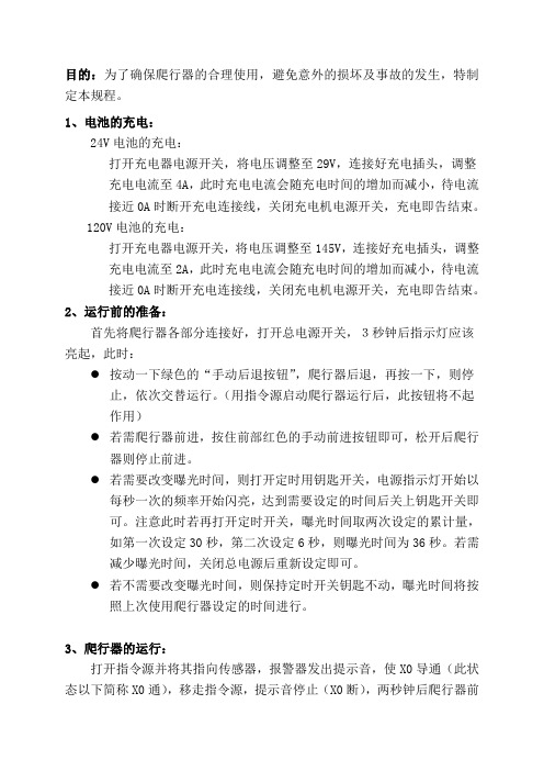
目的:为了确保爬行器的合理使用,避免意外的损坏及事故的发生,特制定本规程。
1、电池的充电:24V电池的充电:打开充电器电源开关,将电压调整至29V,连接好充电插头,调整充电电流至4A,此时充电电流会随充电时间的增加而减小,待电流接近0A时断开充电连接线,关闭充电机电源开关,充电即告结束。
120V电池的充电:打开充电器电源开关,将电压调整至145V,连接好充电插头,调整充电电流至2A,此时充电电流会随充电时间的增加而减小,待电流接近0A时断开充电连接线,关闭充电机电源开关,充电即告结束。
2、运行前的准备:首先将爬行器各部分连接好,打开总电源开关,3秒钟后指示灯应该亮起,此时:●按动一下绿色的“手动后退按钮”,爬行器后退,再按一下,则停止,依次交替运行。
(用指令源启动爬行器运行后,此按钮将不起作用)●若需爬行器前进,按住前部红色的手动前进按钮即可,松开后爬行器则停止前进。
●若需要改变曝光时间,则打开定时用钥匙开关,电源指示灯开始以每秒一次的频率开始闪亮,达到需要设定的时间后关上钥匙开关即可。
注意此时若再打开定时开关,曝光时间取两次设定的累计量,如第一次设定30秒,第二次设定6秒,则曝光时间为36秒。
若需减少曝光时间,关闭总电源后重新设定即可。
●若不需要改变曝光时间,则保持定时开关钥匙不动,曝光时间将按照上次使用爬行器设定的时间进行。
3、爬行器的运行:打开指令源并将其指向传感器,报警器发出提示音,使X0导通(此状态以下简称X0通),移走指令源,提示音停止(X0断),两秒钟后爬行器前进,此时:●X0通的时间若小于等于10秒,即在10秒内移走指令源,爬行器停止前进,延时一段时间(此时间为操作人员撤离射线辐射区的时间,初始设定为10秒)后,X射线发生器开始工作,报警器开始报警,到达设定的曝光时间后报警器停止报警,爬行器前进。
●X0通的时间大于10秒小于等于20秒,报警器发出间断提示音,此时若移走指令源,爬行器后退。
探索探头调试头摄影杆爬行机(PT-EXPR-01)的集装箱操作手册说明书

1What ’s In ThePlease inspect the contents of your shipped package to ensure you have received everything that is listed below.A s s e m b ly M a n u a lAll rights reserved.No part of this document may be reproduced, stored in a retrieval system, or transmitted by any form or by any means, electronic, mechanical, photo -copying, recording, or otherwise, except as may be expressly permitted by the applicable copyrightstatutes or in writing by the Publisher.Explorer Pan Tilt Head for Camera Jib Crane(PT -EXPR-01)Pan Tilt HeadController Box12V AC Adapter 2 x Fuse4 x Washers4 x KnobsO -Ring2 x Camera Bolts (Sizes: 1/4”-20 , 3/8”-16)15mtr Cable3mtr Cable4 x Bolts(Sizes:1/4”-1”)4 x Bolts(Sizes: 1/4”-3/4”)4 x Bolts(Sizes: 1/4”-5/8”)BoltUniversalAdapter23 x T -Type Allen Keys (Sizes: 2.5mm, 4mm, 5mm)2 x L -Type Allen keys (Sizes: 2mm, 3/16”)1 x Spanner (Size: 13)Balancing Tips•Before balancing the camera, Detach the motor gear assembly from the head.NOTE: You can only balance the camera on the head after detaching the motor gear; otherwise, the motor will not function properly.•Then mount your camera on the explorer head's camera plate.•Horizontally balance your camera by placing the camera in the center of the camera plate.•After that, vertically balance your camera by loosening the side knob and increasing it to the desired height, then tighten the knob properly.3•Loosen the Pan Tilt Head ’s Knob and increase its height.Explorer Pro Pan Tilt Head Setup•Then properly tighten the knob, as shown in the image.•Connect the male end of the cable to the female end of the Pan Tilt.Connections of Controller BoxNOTE: Proaim Explorer Pan -Tilt head is precisely engineered, easy to operate & a silent companion for accurate panning & tilting motions.•The camera is now balanced both vertically and horizontally.•Now, reattach the motor gear to the head. NOTE: Make sure that the camera is balanced in all directions depending on its weight so that the motor can function properly when attached.4•Insert the 12-volt AC adapter (4 pin XLR) in the controller box.NOTE: If the Joystick Control is opposite, undo the connectors of motors, rotate 180° and re -install.•Switch ON the controller box, as shown in the image.•Increase/decrease the Panning speed as per your requirements and set the damping.•Attach the second end of the power cable to the universal adapter.•Attach the Power cable to the AC adapter.• Connect the female end of the cable to the controller box.NOTE: Any 12 volt battery may operate this Pan Tilt Head as long as the Connector and the #1 Negative pin & #4 Positive pin of Cable meet together.5•Insert both the knobs and tighten them securely. Follow the same process to insert knobs at the backside as well.•Properly slide the Pan Tilt into the Jib Arm, as shown in the image.NOTE: This 2-Axis pan -tilt head facilitates effortless continuous 360° rotation on both horizontal and vertical axis that gives theoperator full freedom to capture any desired angle.•To change the direction of Panning move the joy -stick to the left and right. And to change the direction of the Tilt, move the joystick back and forth/ up and down.NOTE: Joystick remote controller provides a great range of pan and tilt speed control with an excellent rotation for a complete revolution in any axis.Pan Tilt SetupNOTE: Speed Controller -The Speed Controller adjusts the speed of pan & tilt based on the requirement of the shot.Damping Control -Damping control prevents the Head from stopping with a jerk enabling you to achieve smooth endings.Pan -Tilt Direction -You can reverse the panning & tilting direction as & when required.6NOTE: Adjusting the Camera Angle upside down you capture graceful bird’s eye view shots at ease & it is Suitable for surroundings such as sports events, small and large studios, churches, parliaments, etc.• Insert the bolt and mount the camera (Note Included) properly.Camera Mounting SetupYOUR PROAIM EXPLORER PAN TILT HEADALL DRESSED UP AND READY TO GO!(SHOWN WITH OPTIONAL ACCESSORIES)Warranty: We offer one year warranty for our products from date of purchase. Within this period of time, we will repair it without charge for labor or parts. Warranty doesn’t cover transportation costs nor does it cover a product subjected to misuse or accidental damage. Warranty repairs are subjected to inspection and evaluation by us.Liability: We are not liable for damage caused by products that we do not supply or from mishandling in transit, accident, misuse, neglect, lack of care of the product, or service by anyone other than our company. Contact Us: In case of any kind of dissatisfaction, please Contact us immediately and we promise our utmost support and care until you use our product.。
- 1、下载文档前请自行甄别文档内容的完整性,平台不提供额外的编辑、内容补充、找答案等附加服务。
- 2、"仅部分预览"的文档,不可在线预览部分如存在完整性等问题,可反馈申请退款(可完整预览的文档不适用该条件!)。
- 3、如文档侵犯您的权益,请联系客服反馈,我们会尽快为您处理(人工客服工作时间:9:00-18:30)。
Pipeline Crawler System Operating InstructionsModel: DTPXQ-IIIDandong Flaw-Detection Instrument Factory, ChinaTable of Content1.Introduction42.Main Technical Specifications43.System Components44.Operating Principle55.Installation and Operation65.1.Installation 65.2.Operating the Crawler 66.Maintenance and Precautions7er Instructions of the Magnetic Positioning System87.1.Overview 87.2.Working Principle 87.3.System Components 87.4.Settings and Interface of the Emitter Control Panel 97.5.Receiver Sensitivity Adjustment Instructions 107.6.Main Technical Specifications of the Magnetic Positioning System 117.7.Operating Procedures 117.8.Battery Maintenance and Precautions 147.9.Item List 158.Battery Charger User Instructions158.1.Main Features 158.2.Main Technical Specifications 15er Instructions 169.TH-JBQ-3A Field Radiation Alarm User Instructions179.1.Introduction 179.2.Main Features and Applications 179.3.Main Technical Specifications 17er Instructions 179.5.Cautions 189.6.Supplies: 189.7.Warranty for the alarm 1810.Accessories181.INTRODUCTIONThe DPTXQ-III X-ray Pipeline Crawler System is designed for non-destructive test of circumferential butt welds in pipelines such as gas and oil transmission lines. Thanks to its internal circumferential X-ray tube, it can test single circumferential butt welds with just one exposure. Therefore compares to the common outboard testing in the past, the work efficiency increased dramatically, as well as lowered workload of operations.The main features of the system including compact design, low weight, ease of operation, reliable and wide range of applications.2.MAIN TECHNICAL SPECIFICATIONS•Pipeline diameter range: 600-820mm•Thickness of the pipeline: 5-28mm•Max angle of climb: 38°•Travel speed: 15m/min•Travel distance: 0-1000m (Return)•Weight: 200Kg•Power source: DC batteries (120V)3.SYSTEM COMPONENTSThe Pipeline Crawler System consists of the crawler, magnetic positioning system, X-ray generator, DC battery and recharger, radiation alarm.•Crawler: To move the system inside the pipeline.•Magnetic positioning system: Including emitter and receiver, to direct the crawler moving to the precise welding points.•X-ray generator: Generates X-ray which penetrate through the testing area, to acquire an X-ray image.•DC power: A 120V DC battery, to power the whole system.•Recharger: To recharge the battery.•Radiation alarm: Prompting when the crawler is in exposure mode for safety.Figure 1 - Component Illustration 14.OPERATING PRINCIPLEThe crawler can travel inside the pipeline, when remote instructions are received, they will be processed by the CPU to determine whether to move forwards, backwards or stop, and when to start and stop the exposure process. A varies of tasks can be carried out by sending remote instructions to the system.Figure 2 - Component Illustration IIFigure 3 - Component Illustration III5.INSTALLATION AND OPERATION5.1.Installation•Check the package box to see if it’s intact, without cracks and damage.•After unpacking, check the contents according to the package contents list.•Take out the crawler, and then test whether the screws are loosened.•Select the necessary frames and fasten the screws.•Take out the battery cartridge then put it in the crawler.•Connect the X-ray generator to the device, and make sure it’s fastened.•Connect the various plugs.•Mount the Magnetic Positioning Receiver.•Double check the system to make sure the installation is performed correctly before use.5.2.Operating the Crawler(i)Start:Slide the locked switch to the “Power On” position, the crawler will then start moving forward after 3 seconds.(ii)Moving:The crawler will pause 3 seconds after being switched on or exposure is been performed, after that short period, it will start the motor and moving forward until it receives the positioning signal. While it’s on the move, the alarm will beep in every 10 seconds (Moving Beep), each beep lasts for 1 second.(iii)Positioning:Put the positioning emitter on the desired testing area outside the pipeline, when the crawler reaches that point and its onboard positioning receiver pick up the signal, the crawler will stop moving and proceed to the next phase. There are two kinds of positioning:Positioning while moving FORWARD: When the crawler ismoving forward, it will stop immediately when the positioning signalis being received. If the positioning emitter is off in 0~10 seconds,then the crawler will proceed to delayed waiting phase (Alarm willsound at the same time to indicate waiting state), after 20 seconds theX-ray generator will be powered up by high voltage and the crawlerwill proceed to exposure phase. If the positioning emitter is off at11~20 seconds, the crawler will proceed to backward moving state,and start moving backward (Alarm will sound at the same time toindicate backward moving state).Positioning while moving BACKWARD: When the crawler ismoving backward, alarm will beep once every 10 seconds to indicatethe backward moving state, each beep lasts for 1 second; it will stopimmediately when the positioning signal is being received, and thealarm will generate 1Hz (0.5s on, 0.5s off) sound until thepositioning emitter is off, then the motor will start and the crawler willbe moving forward.(iv)Exposure:When the crawler is in exposure phase, the alarm will make 0.5Hz continuous sound until the end of exposure, after that there’s 2 seconds delay and then the motor will start and the crawler will start moving.(v)Errors:There are three kinds of possible errorsLong exposure error:Normally the exposure time should be lessthan 5 minutes, if the exposure time reaches a certain threshold(Exposure time exceed 8 minutes), and there’s still no instructionfrom the emitter to finish exposure, then X-ray generator will beautomatically forced turned off for safety reason; alarm will go off atthe same time and lasts for 2 second, after that crawler will be forcedto move backward.No positioning signal error:If the crawler continues moving formore than 6 minutes without receiving any positioning signal, it willbe considered that the emitter is faulty, the crawler will then soundthe alarm and automatically returns, this is a procedure to prevent theerror of the magnetic positioning system.Water, obstacles blocking, and low battery error:If the crawlerencounters water or other obstacles when it’s on the move, or thevoltage of the battery is lower than a preset value, the crawler will beforced to go back. This is a security measure to protect the safety ofthe crawler.6.MAINTENANCE AND PRECAUTIONS!1. The outer appearance of the crawler and fastening device need to be visuallychecked and make sure they are in working order after each use; When lifting the machine, make sure to apply forces evenly on each side, and do not twist or pull otherwise it may damage the machine.2. Check the battery regularly; do not discharge the battery completely (refer tothe battery requirements section).3. X-ray generator has poor shock absorption; therefore it should be handledcarefully.4. Although the system is very reliable and it comes with alarm, but all fieldpersonnel should still carry a radiation-warning device to prevent accident. Incase the system failed to carry out exposure procedure, the system should bepulled out immediately and checked thoroughly.5. If the crawler failed to work, then it should be pulled out with emergency towdevice.6. Check the battery level and make sure it’s full before each use.7. It is strictly prohibited to use the crawler in the rain or under severe dampenvironment; If the crawler is splashed with water, the power should be turn offimmediately to prevent short circuit, and make sure to dry it off before use itnext time.ER INSTRUCTIONS OF THE MAGNETIC POSITIONING SYSTEM7.1.OverviewThe main features of the systemincludes powerful penetratingability, high positioning accuracy,no harmful radiation, compactdesign and simple operation, it’s amuch better replacement to the oldgeneration of radioactive isotopecesium 137 locator.7.2.Working PrincipleIt adopts the international leadingtechnology of Eddy Current.7.3.System ComponentsThe system consists of two parts including emitter and receiver.The emitter is a battery-powered portable device; the receiver needs stable and independent DC power that provided by the crawler. The emitter is placed on the outside of the pipeline, and the receiver should be mounted on the top of the crawler inside the pipeline.Figure 4 - Positioning Emitter Figure 5 - Positioning Receiver7.4.Settings and Interface of the Emitter Control Panel1. “Penetrating Properties”buttons area: it has three levels, including Thin, Medium and Thick, from weak to strong penetration, select these according to the thickness of the testing material to meet different field testing requirement. Choose “Thin” for small pipeline with thickness of 10mm; choose “Medium” for t h i c k n e s s l e s s t h a n 20mm; choose “Thick” for thickness more than 20mm.2. “+15V +5V -15V” Indicator LED: Indicating the working condition of the emitter’s internal circuit, all three should be o n u n d e r n o r m a l operating conditions.3. “Strength Adjustment” button area: to adjust thepower of the transmission.Greater value indicates strongermagnetic field emission. Theoretical values on the display ranges from 0 to 255, however the real figures are generally smaller, for example “thin” level is usually less than 50, “medium” is usually less than 100, and “thick” is usually less than 150. More magnetic emission power means greater power consumption, therefore it’s not recommended to continuously working under the maximum power for that penetrating setting (It’s when the power wouldn’t increase any more after keeping press the up arrow button).4. “Up” and “Down” buttons in the strength adjustment area: Press “Up” arrow to increase the power, press “Down” arrow to decrease the power.5. “Rapid/Fine Tune”button: To adjust the increase/decrease speed of the strength adjustment. The LED indicator lights up when it’s in “Fine Tune” mode. The default mode is “Rapid Tune”, press the button to switch between these two modes.6. “Voltage Alarm”button: LED for this button does not light normally, but when the voltage is too low (around 27V), the LED will light up and the buzzer will sound immediately to remind the user to recharge the battery of the emitter. The battery should last 10~30 minutes depends on different power settings. Press the button to turn off the alarm state, and the LED indicator will go off.Figure 6 - Emitter Control Panel7. “V/I Monitor”button: press to switch monitoring between voltage andcurrent; If the LED lights up then it’s in the “Current Mode”, the figures showing on the display is the power of the transmission, you can only adjust the power strength in this mode. Press it again to switch to Voltage mode, the LED goes off and you cannot change the power strength in this mode.8. “Set/Lock” button: to lock or unlock settings. You need to press this keyfirst to unlock the settings, and then adjust the penetrating level followed by power strength, after that you may press this button again to lock the settings, the display will flash 2~5 seconds to indicate the system is saving the new settings.9. “Power Saving” switch: it’s close to the handle on the upper side, switchthis off the system will then proceed to power saving mode, and all the settings should be saved; switch this on and the system will power up, ready to work without the need of setting the parameters again. You don’t need to use this switch for a short period of operating time.10. “Power” Switch with lock: The system will boot up after switch it on,and then preform self-test which lasts for around 5 seconds, the figures showing on the display becomes stable. After switch off the system, the power will be cut off completely; all settings will be saved without the need of setting the parameters again.11. Charging Sockets7.5.Receiver Sensitivity Adjustment Instructions1. Two small switches at the bottom of the receiver (in some models theseswitches are at the back of the receiver) which can set 4 different level of sensitivity, showing on the figure below.2. From level 1 to level 4, thesensitivity goes from weak to strongaccordingly. In coordination withdifferent penetration level on theemitter (thin, medium and thick), tosuit a wide range of pipeline withvaries thickness.3. If the transmission cannotpenetrate the pipeline with themaximum power setting on theemitter, you may increase thesensitivity of the receiver.Figure 7 - Sensitivity Settings4. It is recommended to use level 2sensitivity for pipe with thickness less than10mm, and diameter less than 300mm; level 3 sensitivity is used morefrequently for thickness less than 20mm; You may use level 4 sensitivity for thickness more than 20mm; for thickness more than 30mm you should always use level 4sensitivity.5. Note: If there’s serious magnetic interference nearby (from high-voltagewires, transformer substation etc.), You may lower one level of sensitivity on the receiver, and increase the penetrating power on the emitter. Any kind of motor operating around the testing site should be kept away to avoid the direct interference.7.6.Main Technical Specifications of the Magnetic Positioning SystemEmitter:•Input Voltage: DC32V±8V•Rated Power: ≤50W•Penetrating Power: ≤30mm•Weight: 4.7kg•Operating Temperature: -40℃ ~ 80℃•Working Time: more than 8 hours•Size: 225 x110 x 195mmReceiver:•Input Voltage: DC12V/24V±3V•Rated Power: ≤4.8W•Crawler Speed: ≤30m/min (Recommend constant speed: ≤20m/min)•Weight: 0.5kg•Operating Temperature: -40℃ ~ 80℃•Receiver Sensitivity: 4 levels adjustable•Distance between the receiver and the top (inside) of the pipe: 5~10cm (If crawler has large deviation of track, then 10~20cm is recommended)•Accuracy of positioning: ±5mm•Size: 100 x 110 x 27mmAluminum Protective Case: 400 x 315 x 350mmBattery Charger: 220AC/DC16.8V/1.0A Standard Charger7.7.Operating Procedures(i)Transmission Level Setting:Power level on the emitter and sensitivity level on the receiver shouldbe set according to the pipe’s diameter and thickness.(ii)Correct wiring for the receiver:Wiring:Color of power cord: Red (+), White (-)Color of signal cord: Orange, GreyTechnical Standard for the receiver:Power Supply: DC 24VOutput Signal Type: Passive switch(iii)Setting up the devices1. Mount the receiver: Mount the receiver to the front part of thecrawler (away from the motor side), the distance between receiver and the top of the pipe wall should be appropriate. Connect the cable between the receiver and the crawler (Correct wiring needed, otherwise it may damage the receiver or fail to receive the signals), and then tighten up the connectors. Put the crawler into the opening of the pipeline, make sure the receiver is about 1m into the pipeline so that it’s possible to observe the receiver’s LED status.2. Switch off the power of the motor on the crawler, or lift up thewheels, to make sure the crawler doesn’t move while adjusting the signal strength.3. Placing and starting the emitter: Put the emitter on the outer wall ofthe pipe, control panel facing the user, and ensure the emitter is basically in the same vertical line to the receiver. Use the key to switch on the emitter, and then turn on the power saving mode (If the power saving switch is being turned on beforehand, then the emitter will not boot up normally). It may take a few seconds for the emitter to do the self-test, reload the settings from last time. Remember you need to turn off power saving mode before switch off the emitter, and use the key to lock the power switch after that. Continuous power up interval should be more than 5 seconds.4. Adjusting the transmission power: If the blue indicator LED on thereceiver doesn’t light up, increase the emitter’s power by press the up arrow button in the “Penetrating Strength” area, when the blue LED lights up and become stable (not flashing), increase the power a few more steps to ensure a good reception (the emitter can only send signal to the receiver when the blue LED is on), then lock the setting by press the “Set/Lock” button. While adjusting the transmission power, the red LED on the receiver lights up first, and then blue LED lights up. You may also adjust the position of the receiver horizontally so that it’s in the same vertical line to the emitter.If the blue LED on the receiver already lit up without any adjustment, there’s two ways to re-ensure that the transmission power is sufficient. One way to do this is that you may lower the power on the emitter, up to a point where the blue LED on the receiver turns off,and then you may re-adjust again by increase the emitter’s power using the method above; Another way to make sure the transmission power is sufficient, is that you may simply just increase the power a couple of more steps, however this may cause the receiver picks up the signal earlier than desired, and making the crawler stops prematurely, thus to make the whole positioning process inaccurate.5. Do a test run on the crawler first in a short pipeline, and determinethe appropriate distance between the welds and where you should place the emitter.(iv)Operating1. Switch on the crawler, put the emitter close to the outer surface ofthe pipeline, then move it away slowly following the pipeline to send out the signal, the crawler should start working.2. When the crawler starts working, place the emitter on the upperwall of the pipeline close to the weld point, make sure it’s in the same vertical line to the receiver (otherwise it may cause positioning inaccurate).3. After the positioning process finish, take the emitter and move it tothe next testing (welds) point. While moving emitter, the head of the emitter (the side with the locked switch) should be kept facing the same way, and user should also observe the power value on the control panel display, it’s normal if the value changes up or down 1 level.(v)Attention while in operating1. The settings for the emitter (including penetrating level andtransmission strength) should be re-adjusted for pipe with different diameter and/or wall.2. The variation of the distance between the emitter and pipelineshould not exceed 2mm, otherwise you may re-adjust the transmission power (especially for the repositioning when the crawler re-enter the pipeline).3. If necessary, use the power saving switch close to the handle whilecarrying it from one weld point to another, remember to turn it back on upon reaching the next point.4. The receiver is only designed to work inside the pipeline, when it’sout in the open and exposed to the magnetic field for too long, it may damage the receiver.5. The sensitivity level on the receiver cannot be changed while thepower is on, to change it you need to turn off the power first, and thenturn it back on after the new sensitivity level is being set.6. The speed of the crawler may change due to power consumption,and this may affect the positioning accuracy. It is recommended to usethe Magnetic Positioning System on a crawler with steady speedability.7. Try not to set the speed of the crawler too fast, and make sure it’smoving in a straight line, otherwise it may affect the positioningaccuracy.8. The inside and outside surface of the pipeline may be painted withsome special anti-corrosion, anti-static and anti-magnetic materials,when this affects the penetrating ability of the emitter, adjust thepenetrating power of the emitter as well as the sensitivity of thereceiver accordingly.9. After positioning, the crawler proceeds to exposure phase, duringthis period, some electrical parts inside the crawler may generate mildinterference to the receiver, however the signal can be shielded bysetting up certain program during exposure phase.7.8.Battery Maintenance and Precautions1. Battery should not be charged continuously for over 24 hours, or it mayaffect the lifespan of the battery.2. When the battery is not being used for more than a month, you needperform a discharge and recharge to protect the battery.3. If the display on the control panel showing 28 or less when pressing the“V/I” button, it’s not in a good state for long time use; when the low-voltage alarm beeps, you should recharge the battery as soon as possible orthe emitter may turn off automatically.4. When the emitter is in Power-Saving mode(The main locked switch is still on), because thepower is not completely turned off, therefore itwill still drain the battery slowly. Remember toturn off the locked power switch and put it inthe storage case after use.5. To charge the battery, plug the two chargingcables into the two sockets separately. Whenthe LED indicator turns from red to blue, itmeans the charging completed.Figure 7 - Charging Sockets7.9.Item List•Magnetic Positioning Emitter•Magnetic Positioning Receiver•33V/4.8AH High Capacity Rechargeable Battery (pre-installed in the emitter)•Accessories: Battery Charger x2, DC16.8V/1.0A Standard Charger•Accessories: Protective Storage Case•Accessories: Protective Storage Case Key x2, (silver color)•Accessories: Emitter power switch keys x2 (with black handle)8.BATTERY CHARGER USER INSTRUCTIONS8.1.Main FeaturesFigure 9 - Battery Charger•Wide input voltage range•Output voltage value can be adjusted continuously from 120~150V•Output current value can be adjusted continuously from 0.5~5A•To increase the output current, more units can be set in parallel without the need of current process•Input: over-current, over-voltage, under-voltage protection; Output: short circuit, over-current, over-voltage protection; Overheating protection•Intelligent temperature-controlled fan cooling8.2.Main Technical Specifications•Environmental ConditionsOperating Temperature: -20~50℃;Storage Temperature: -40~70℃;Relative Humidity: 90% (40±2℃);Atmospheric Pressure: 70~106 kPa•Dimensions and Weight: 250mm x 210mm x 68mm 3.2Kg•Input Voltage: AC180~264V Frequency: 50Hz±10%•Output Voltage: DC120~150V (factory setting 5A)•Efficiency >90%•Power Factor >0.85•Load Regulation <1%•Voltage Regular <0.1%•Ripple Voltage <1%•ProtectionInput: over-current, over-voltage, under-voltage protection;Output: short circuit, over-current, over-voltage protection;Overheating protection•Thermal Protection Threshold: 80~85℃•Insulation Resistance ≥20MΩ•MTBF ≥50000her Instructions1. Check before connecting the power: observe to see if there’s any damagedue to transportation, such as loosen screws, strange appearance etc.Proper measures should be taken if any problems are being found.2. Connection: connect the safety ground wire and power cord; make surethe connection is correct and firmly tightened.3. Select charging conditions: turn the “Charging Current Selection” knobto 2A; charging time is 10 hours, increase the current appropriately to speed up the charging. Charging voltage should be selected as 135V.4. No-load power up: turn on the power switch, and then output voltageshould be appeared on the voltmeter. Use a small screwdriver to adjust the output voltage setting on the panel to a desired value, turn it clockwise to increase the voltage, counterclockwise to reduce the voltage.5. Connect the output cable: turn off the power, connect the cable to thecharger and rechargeable battery according to the marks on the panel, red wire to the (+) terminal on the charger, green wire to the (-) terminal. Make sure the connection is correct and then connect the 5-pin plug to the battery. Extra caution should be taken as wrongly connection to the terminals may damage the device. All connectors should be connected firmly.6. Adjust charging current: turn on the power, use a small screwdriver toadjust the output current setting on the panel to a desired value (adjustment can only work when there’s input current), turn it clockwise to increase the current, counterclockwise to reduce the current.7. Cooling fan is temperature-controlled, when the internal temperatureexceeds certain point, the cooling fan will be triggered to start, fan speedvaries with different output voltage and current settings, this is normal; When it’s working, do not block the ventilation of the fan.8. When the internal temperature of the device reaches the auto-shutdown threshold, the device will automatically stop working to protect it from being damaged; when the temperature dropped the device will restart and work again.9.Warning: do not charge the battery until you’ve checked the charger is in working order.9.TH-JBQ-3A FIELD RADIATION ALARM USER INSTRUCTIONS9.1.IntroductionThis product is designed according to the special requirement of industrial X-ray testing site, it features a new looking, and wirelessly radiation detection, small size and low weight, high output power, alarm with sound and flashlight, easy to carry.9.2.Main Features and Applications•Alarm with sound and flashlight, 360°sound field •It is widely used in the field of X-ray and γ-ray testing, γ source transportation and indoor monitoring system.9.3.Main Technical Specifications•Sound Pressure: ≥80dB •Sound Frequency: 900Hz •Intermittent Frequency: 1.5Hz •X-ray detection range: 20 meters (open area)•Power Consumption: ≤25W •Size: Φ200mm , Height 225mm •Weight: 3.5kg •Battery Life: 8 Hourser Instructions1. Turn on the alarm by pushing the switch to the “Working” mode, and then place it on a suitable surface.Figure 10 - Radiation Alarm2. Adjust the volume by rotate the control knob to an appropriate level.3. When X-ray is being detected, siren will sound with flashlights.4. Siren will continue to sound for 6 more seconds after X-ray detection isgone, due to the internal data refresh rate.5. Turn the switch back to “Charging” mode when finish.6. The alarm needs to be recharged after working for 8 hours, make sure theswitch is on “Recharge” mode, and then connect the battery charger plug to the alarm, the LED showing green light, the battery should be fully recharged approximately 15 hours.9.5.Cautions1. Only use the supplied charger to charge the battery.2. Handle with care.3. The LED also doubles as a low-power indicator, it will show red lightwhen the battery is really low, and alarm will stop working and should be recharged as soon as possible.9.6.Supplies:Charging Power Adaptor x19.7.Warranty for the alarmManufacturer can repair it for 6 months starting the date of sale.10.ACCESSORIESFor different pipelines with different diameters, there’s varies accessories you can choose for the system, please find it on the separate accessories list.。