An extensible, modular architecture for simulating urban development, transportation, and e
仿生建筑总结范文英文

Biomimicry, the practice of emulating nature's efficient designs, has emerged as a revolutionary approach in the field of architecture. This summary aims to provide an overview of the key concepts, applications, and benefits of biomimicry in architecture.IntroductionArchitecture has historically been influenced by various factors, including cultural, social, and technological advancements. However, with the increasing awareness of environmental sustainability, biomimicry has gained significant attention as a means to create buildings that are not only functional but also harmonious with nature. By studying and replicating the strategies employed by nature,architects can design structures that are energy-efficient, durable, and aesthetically pleasing.Key Concepts of Biomimicry in Architecture1. Inspiration from NatureThe core concept of biomimicry in architecture is to draw inspiration from nature's designs. This involves studying the ways in which living organisms adapt to their environments and incorporating these strategies into building design. For example, the structure of a honeycomb is an efficient use of space, which has been replicated in the design of honeycomb-shaped solar panels.2. Self-Organizing SystemsNature has developed self-organizing systems that are highly efficient and adaptable. Biomimicry in architecture aims to mimic these systems, such as the self-healing properties of human skin or the modular nature of certain plants. By incorporating these concepts, architects can create buildings that are more resilient and adaptable to changing conditions.3. Passive DesignPassive design is a key aspect of biomimicry in architecture. This approach focuses on using natural systems to reduce the need forartificial energy sources. Examples include the use of natural ventilation, solar shading, and thermal mass to regulate indoor temperatures. This not only reduces energy consumption but also creates a more comfortable living environment.Applications of Biomimicry in Architecture1. Green RoofsGreen roofs, also known as living roofs, are an excellent example of biomimicry in architecture. These roofs are covered with vegetation, which helps to insulate the building, reduce stormwater runoff, and improve air quality. This concept is inspired by the natural insulating properties of vegetation found in nature.2. Geothermal EnergyGeothermal energy is another application of biomimicry in architecture. By tapping into the Earth's natural heat, buildings can be heated or cooled without the need for traditional energy sources. This approach is inspired by the Earth's internal heat, which is a key factor in regulating the planet's climate.3. Structural InsulationThe use of natural materials, such as bamboo or straw, for structural insulation is another example of biomimicry in architecture. These materials have excellent insulating properties and are biodegradable, making them a sustainable alternative to traditional insulation materials.Benefits of Biomimicry in Architecture1. Energy EfficiencyBy emulating nature's efficient designs, biomimicry in architecture can significantly reduce energy consumption, leading to lower utility bills and a smaller carbon footprint.2. Environmental SustainabilityBiomimicry promotes the use of sustainable materials and practices, which helps to minimize the impact of buildings on the environment.3. Aesthetic and Health BenefitsBiomimicry in architecture can lead to aesthetically pleasing buildings that enhance the well-being of their occupants. Natural materials and design principles can contribute to a healthier indoor environment, reducing stress and promoting relaxation.ConclusionBiomimicry in architecture offers a promising approach to creating sustainable, energy-efficient, and aesthetically pleasing buildings. By studying and emulating nature's designs, architects can design structures that are not only functional but also harmonious with the environment. As the world becomes increasingly aware of the importance of sustainability, biomimicry is poised to play a significant role in shaping the future of architecture.。
NI Hil测试系统介绍及组成说明书
Architectures for Implementing a Hardware-in-the-Loop SystemOverviewYou can test embedded control systems more efficiently with the powerful method of hardware-in-the-loop (HIL) simulation. Safety, availability, or cost considerations can make it impractical to perform all the necessary tests with the complete embedded control system. Using HIL simulation, you can simulate the parts of the system that pose these challenges. By thoroughly testing the embedded control device in a virtual environment before proceeding to real-world tests of the complete system, you can maintain reliability and time-to-market requirements in a cost-effective manner even as the systems you are testing become more complex.ContentsComponents of an HIL Test System (2)Hardware Fault Insertion (2)Testing Multi-ECU Systems (2)Additional Processing Power—Distributed Processing (3)Simplified Wiring—Distributed I/O (4)Implementing HIL Test Systems (4)Next Steps (5)Components of an HIL Test SystemAn HIL test system consists of three primary components: a real-time processor, I/O interfaces, and an operator interface. The real-time processor is the core of the HIL test system. It provides deterministic execution of most of the HIL test system components such as hardware I/O communication, data logging, stimulus generation, and model execution. A real-time system is typically necessary to provide an accurate simulation of the parts of the system that are not physically present as part of the test.The I/O interfaces are analog, digital, and bus signals that interact with the unit under test. You can use them to produce stimulus signals, acquire data for logging and analysis, and provide the sensor/actuator interactions between the electronic control unit (ECU) being tested and the virtual environment being simulated by the model. The operator interface communicates with the real-time processor to provide test commands and visualization. Often, this component also provides configuration management, test automation, analysis, and reporting tasks.Figure 1. An HIL test system consists of three primary components: an operator interface, a real-timeprocessor, and I/O interfaces.Hardware Fault InsertionMany HIL test systems use hardware fault insertion to create signal faults between the ECU and the rest of the system to test, characterize, or validate the behavior of the device under these conditions. To accomplish this, you can insert fault insertion units (FIUs) between the I/O interfaces and the ECU to allow the HIL test system to switch the interface signals between normal operation and fault conditions such as a short-to-ground or open circuit.Figure 2. You can use hardware fault insertion to test the behavior of the ECU during signal faults. Testing Multi-ECU SystemsSome embedded control systems, such as an automobile, aircraft, or wind farm, use multiple ECUs that are often networked together to function cohesively. Although each of these ECUs may initially be testedindependently, a system’s integration HIL test sys tem, such as a full vehicle simulator or iron bird simulator, is often used to provide more complete virtual testing. When testing a multi-ECU control system (and even some single ECU control systems), two needs often arise: additional processing power and simplified wiring.Figure 3. Automobiles, aircraft, and wind farms use multiple ECUs. Additional Processing Power—Distributed ProcessingEven with the latest multicore processing power, some systems require more processing power than what is available in a single chassis. To address this challenge, you can use distributed processing techniques to meet the performance requirements of these systems. In very high-channel-count systems, the need is more than simply additional processing power, additional I/O is also necessary. In contrast, systems using large, processor-hungry models often use additional chassis only for the extra processing power, allowing those processors to remain dedicated to a single task for greater efficiency. Depending on how the simulator tasks are distributed, it may be necessary to provide shared trigger and timing signals between the chassis as well as deterministic data mirroring to allow them to operate cohesively.Figure 4. When using multiple chassis for additional processing power, it is often necessary to provide timing and data synchronization interfaces between them.Simplified Wiring—Distributed I/OImplementing and maintaining wiring for high-channel-count systems can pose costly and time-consuming challenges. These systems can require hundreds to thousands of signals be connected between the ECU and the HIL test system, often spanning many meters to compensate for space requirements.Fortunately, deterministic distributed I/O technologies can help you tame these wiring complexities and provide modular connectivity to ECUs, which allows for efficient system configuration modifications. Instead of routing all connections back to a single rack containing one or more real-time processing chassis instrumented with I/O interfaces, you can use deterministic distributed I/O to provide modular I/O interfaces located in close proximity to each ECU without sacrificing the high-speed determinism necessary for accurate simulation of the virtual parts of the system.This approach greatly reduces HIL test system wiring cost and complexity by making it possible for the connections between the ECU and the I/O interfaces to be made locally (spanning less than a meter) while a single bus cable is used to span the additional distance to the real-time processing chassis. Additionally, with the modular nature of this approach, HIL test systems can easily scale, incrementally, from a multi-ECU test system in which all but one of the ECUs are simulated to a complete system integration HIL test system where none of the ECUs are simulated.Figure 5. Deterministic distributed I/O interfaces greatly reduce HIL test system wiring cost and complexity because the connections between the ECU and the I/O interfaces can be made locally. Implementing HIL Test SystemsAfter you have selected the appropriate architecture for your HIL test system, the first step in creating a HIL test system is to select the components that best meet your development requirements. NI provides a wide variety of real-time processing and I/O options for implementing HIL test systems. Because they are all based on open industry standards, you can be assured that they always deliver the latest advances in PC technology to your HIL test system and always meet future test system requirements.The NI HIL platform is open and extensible, which means that it can adapt to changing system requirements. Because of its modular architecture, the NI HIL platform can be easily upgraded with additional functionality, which helps you future proof your test systems and meet the requirements of the most demanding embedded software testing applications. In addition to the widest range of I/O on market, NI offers software tools that help you automate your HIL tests, perform post-processing and report generation, and map test results to requirements. These tools help you perform a wider range of tests earlier in the software development process, which reduces overall development cost while improving product quality.。
Contributions
A Proof Environment for Specifications
March th,
/ in a Nutshell
e Object Constraint Language ()
Textual extension of the Allows for annotating diagrams In the context of class–diagrams:
invariants preconditions postconditions
Practice:
A machine checked semantics for .
Achim D. Brucker ( Zurich)
A Proof Environment for Specifications
March th,
/ in a Nutshell
context Account inv: 0 <= id
Account balance:Integer id:Integer 1..* getId():Integer accounts getBalance():Integer deposit(a:Integer):Boolean withdraw(a:Integer):Boolean
Achim D. Brucker ( Zurich)
A Proof Environment for Specifications
March th,
/ in a Nutshell
The Object Constraint Language ()
e Object Constraint Language ()
Outline
Modular server architecture for multi-environment
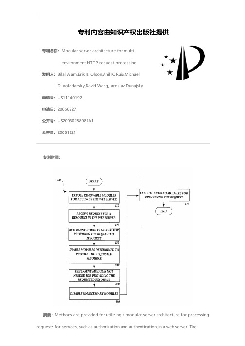
专利名称:Modular server architecture for multi-environment HTTP request processing发明人:Bilal Alam,Erik B. Olson,Anil K. Ruia,MichaelD. Volodarsky,David Wang,Jaroslav Dunajsky申请号:US11140192申请日:20050527公开号:US20060288085A1公开日:20061221专利内容由知识产权出版社提供专利附图:摘要:Methods are provided for utilizing a modular server architecture for processing requests for services, such as authorization and authentication, in a web server. Themodular server architecture includes self-contained modular components that can be plugged in and out of the web server, as needed, to provide requested web services. The modular server architecture is also extensible in that it provides set of server APIs for processing requests for supporting built-in server functionality as well as functionality provided by third party modular components. The modular server architecture also supports the integration of request processing tasks for both native and managed modular components, such as modules, by virtue of a managed module host component. The modular server architecture also optimizes server performance by only providing modular component functionality when needed. By utilizing the modular server architecture, server functionality is extended, duplication of request processing tasks is eliminated and performance administrative overhead is reduced.申请人:Bilal Alam,Erik B. Olson,Anil K. Ruia,Michael D. Volodarsky,David Wang,Jaroslav Dunajsky地址:Sammamish WA US,Sammamish WA US,Issaquah WA US,Seattle WA US,Issaquah WA US,Redmond WA US国籍:US,US,US,US,US,US更多信息请下载全文后查看。
北京地铁10号线综合监控系统简介

北京地铁10号线综合监控系统简介张发明1 王 颖2(中铁电气化局集团一公司,100070,北京;2.北京市轨道交通建设管理有限公司,100032,北京∥第一作者,工程师)摘 要 综合监控系统是一个功能强大的、开放的、模块化的、可扩展的分布式控制系统,集成和互联了多个子系统。
介绍了北京地铁10号线综合监控系统的构成。
北京地铁10号线综合监控系统的集成部分包括供电监控、环境与设备监控、站台屏蔽门、有线广播、闭路电视等子系统;互联部分包括北京市轨道交通指挥中心、火灾自动报警、列车自动监控、传输、时钟、无线通信、自动售检票、乘客信息、通信专业集中告警设备等子系统。
详细介绍了各子系统的具体功能。
综合监控系统将提高自动化系统的安全性、可靠性及快速响应能力,实现高性价比,减少重复投资和后期维护成本。
综合监控系统为地铁运营管理提供了信息集成平台。
关键词 地铁,运营管理,综合监控系统中图分类号 U 231+.92I ntegrated Supervision and Control System for B eijing Metro Line 10Zhang Faming ,Wang Y ingAbstract Integrated Supervision and Control System is a pow 2erful ,open ,modular ,extensible distributed control system ,in 2tegrating and interconnecting many subsystems.This paper in 2troduces the constitution of Integrated Supervision and Control System for Beijing Metro Line 10.The integration parts of this system include power supply monitor ,environment and equip 2ment monitor ,platform shield gate ,cable ,closed circuit televi 2sion and other subsystems.Beijing Urban Rail Control Center ,the automatic fire alarm ,the automatic train control ,transmis 2sion ,the clock ,wireless communications ,the automatic fare checking ,passenger information ,and alarm focused communica 2tion equipment and other subsystems are the interconnect parts of it.The specific functions of these subsystems are presented in de 2tail.The author concludes that the Integrated Supervision and C on 2trol System will enhance the safety ,reliability and rapid response a 2bility of the automatic system to achieve higher performance 2cost ra 2tio and to reduce repeated investment and maintenance cost in the later period.The system als o provides an information 2integrating platform for the subway operation management.K ey w ords metro ,management of operation ,integrated su 2pervision and control systemFirst 2author ’s address First Engineering Co.,Ltd.of China Railway Electnification Bureau Group ,100070,Beijing ,China 我国地铁的综合监控经历了从单一到组合、分立到综合的过程。
Juniper Networks SRX5400、SRX5600和SRX5800服务网关产品描述说明

The SRX5400, SRX5600, and SRX5800 are supported by Juniper Networks Junos®Space Security Director, which enables distributed security policy management through an intuitive, centralized interface that enables enforcement across emerging and traditional risk vectors. Using intuitive dashboards and reporting features, administrators gain insight into threats, compromised devices, risky applications, and more.Based on Juniper’s Dynamic Services Architecture, the SRX5000 line provides unrivaled scalability and performance. Each services gateway can support near linear scalability with the addition of Services Processing Cards (SPCs) and I/O cards (IOCs), enabling a fully equipped SRX5800 to support up to 1.2 Tbps firewall throughput. The SPCs are designed to support a wide range of services, enabling future support of new capabilities without the need for service-specific hardware. Using SPCs on all services ensures that there are no idle resources based on specific services being used—maximizing hardware utilization.The scalability and flexibility of the SRX5000 line is supported by equally robust interfaces. The SRX5000 line employs a modular approach, where each platform can be equipped with a flexible number of IOCs that offer a wide range of connectivity options, including 1GbE, 10GbE, 40GbE, and 100GbE interfaces. With the IOCs sharing the same interface slot as the SPCs, the gateway can be configured as needed to support the ideal balance of processing and I/O. Hence, each deployment of the SRX Series can be tailored to specific network requirements. The scalability of both SPCs and IOCs in the SRX5000 line is enabled by the custom-designed switch fabric. Supporting up to 960 Gbps of data transfer, the fabric enables realizationof maximum processing and I/O capability available in any particular configuration. This level of scalability and flexibility enables future expansion and growth of the network infrastructure, providing unrivaled investment protection.The tight service integration on the SRX Series is enabled by Juniper Networks Junos® operating system. The SRX Seriesis equipped with a robust set of services that include stateful firewall, intrusion prevention system (IPS), denial of service (DoS), application security, VPN (IPsec), Network Address Translation (NAT), unified threat management (UTM), and quality of service (QoS). In addition to the benefit of individual services, the SRX5000 line provides a low latency solution.Junos OS also delivers carrier-class reliability with six nines system availability, the first in the industry to achieve independent verification by Telcordia. Furthermore, the SRX Series enjoys the benefit of a single source OS, and single integrated architecture traditionally available on Juniper’s carrier-class routers and switches.SRX5800The SRX5800 Services Gateway is the market-leading security solution supporting up to 1.2 Tbps firewall throughput and latency as low as 32 microseconds for stateful firewall. The SRX5800 also supports 1 Tbps IPS and 390 million concurrent sessions. Equipped with the full range of advanced security services, the SRX5800 is ideally suited for securing large enterprise, hosted, or colocated data centers, service provider core and cloud provider infrastructures, and mobile operator environments. The massive performance, scalability, and flexibility of the SRX5800 make it ideal for densely consolidated processing environments, and the service density makes it ideal for cloud and managed service providers.SRX5600The SRX5600 Services Gateway uses the same SPCs and IOCsas the SRX5800 and can support up to 570 IMIX Gbps firewall throughput, 460 million concurrent sessions, and 460 Gbps IPS. The SRX5600 is ideally suited for securing enterprise data centers as well as aggregation of various security solutions. The capability to support unique security policies per zone and its ability to scale with the growth of the network infrastructure make the SRX5600 an ideal deployment for consolidation of services in large enterprise, service provider, or mobile operator environments. SRX5400The SRX5400 Services Gateway uses the same SPCs and IOCs as the SRX5800 and can support up to 285 Gbps IMIX firewall, 90 million concurrent sessions, and 230 Gbps IPS. The SRX5400 is a small footprint, high-performance gateway ideally suited for securing large enterprise campuses as well as data centers, either for edge or core security deployments. The ability to support unique security policies per zone and a compelling price/performance/footprint ratio make the SRX5400 an optimal solution for edge or data center services in large enterprise, service provider, or mobile operator environments. Service Processing Cards (SPC)As the “brains” behind the SRX5000 line, SPCs are designedto process all available services on the platform. Without the need for dedicated hardware for specific services or capabilities, there are no instances in which a piece of hardware is taxedto the limit while other hardware is sitting idle. SPCs are designed to be pooled together, allowing the SRX5000 line to expand performance and capacities with the introduction of additional SPCs, drastically reducing management overhead and complexity. The high-performance SPC3 cards are supported on the SRX5400, SRX5600, and SRX5800 Services Gateways.I/O Cards (IOCs)To provide the most flexible solution, the SRX5000 line employs the same modular architecture for SPCs and IOCs. The SRX5000 line can be equipped with one or several IOCs, supporting the ideal mix of interfaces. With the flexibility to install an IOC or an SPC on any available slot, the SRX5000 line can be equipped to support the perfect blend of interfaces and processing capabilities, meeting the needs of the most demanding environments while ensuring investment protection. Juniper offers the IOC2, a second-generation card with superior connectivity options. The IOC2 offers the industry’s first100GbE as well as 40GbE and high-density 10GbE and 1GbE connectivity options. These options reduce the need for link aggregation when connecting high throughput switches to the firewall, as well as enabling increased throughput in the firewall itself. The IOC2 is supported on all three platforms in theSRX5000 line of services gateways.The third generation of IOCs from Juniper, the IOC3, delivers the highest throughput levels yet, along with superior connectivity options including 100GbE, 40GbE, and high-density 10GbE interfaces. The IOC2 or IOC3 operates with the Express Path optimization capability, delivering higher levels of throughput—up to an industry-leading 2 Tbps on the SRX5800. The IOC3 cards are supported on the SRX5400, SRX5600, and SRX5800.Routing Engine (RE2) and Enhanced System Control Board (SCB3)The SRX5K-RE-1800X4 Routing Engine (RE2) is the latest in the family of REs for the SRX5000 line with a multicore processor running at 1800 MHz. It delivers improved performance, scalability, and reliability with 16 GB DRAM and 128 GB solid-state drive (SSD). The SRX5K-SCB3 Enhanced System Control Board (SCB3) enables 240 Gbps per slot throughput with intra as well as interchassis high availability and redundancy.Features and BenefitsNetworking and SecurityThe Juniper Networks SRX5000 line of Services Gateways has been designed from the ground up to offer robust networking andsecurity services.*Requires Junos OS 15.1x49-D10 or greater.**Requires Junos OS 18.2R1-S1 or greater.IPS CapabilitiesJuniper Networks IPS capabilities offer several unique features that assure the highest level of network security.Content Security UTM CapabilitiesThe UTM services offered on the SRX5000 line of Services Gateways include industry-leading antivirus, antispam, content filtering,and additional content security services.Advanced Threat PreventionAdvanced threat prevention (ATP) solutions that defend against sophisticated malware, persistent threats, and ransomware are available for the SRX5000 line. Two versions are available: Juniper Sky ATP, a SaaS-based service, and the Juniper ATP Appliance, anon-premises solution.More information about Juniper Sky ATP can be found at /us/en/products-services/security/sky-advanced-threat-prevention/. Additional information about the Juniper ATP Appliance can be found at /us/en/products-services/ security/advanced-threat-prevention-appliance/.Centralized ManagementJuniper Networks Junos Space Security Director delivers scalable and responsive security management that improves the reach, ease, and accuracy of security policy administration. It lets administrators manage all phases of the security policy life cycle through a single web-based interface, accessible via standard browsers. Junos Space Security Director centralizes application identification, firewall, IPS, NAT, and VPN security management for intuitive and quick policy administration. Security Director runs on the Junos Space Network Management Platform for highly extensible, network-wide management functionality, including ongoing access to Juniper and third-party Junos Space ecosystem innovations.Specifications1FirewallSRX5600Services GatewaySRX5800Services GatewaySRX5400Services Gateway Performance, capacity and features listed are based on systems running Junos OS 15.1x49 and are measured under ideal testing conditions. Actual results may vary based on Junos OS releases and by deployments. Maximum concurrent sessions and new sessions/second improvements are a result of Junos 15.1X49-D30.* Session capacity differs based on UTM/AppSecure/IPS features enabled.Please consult the technical publication documents and release notes for a list of compatible ISSU features.T o enable dual control links on the SRX5000 line, two SRX5K-RE-1800X4 modules must be installed on each cluster member.SRX5000 line of gateways operating with Junos OS release 10.0 and later are compliant with the R6, R7, and R8 releases of 3GPP TS 20.060 with the following exceptions (not supported on the SRX5000 line): - Section 7.5A Multimedia Broadcast and Multicast Services (MBMS) messages- Section 7.5B Mobile Station (MS) info change messages- Section 7.3.12 Initiate secondary PDP context from GGSNShort term is not greater than 96 consecutive hours, and not greater than 15 days in 1 year.WarrantyFor warranty information, please visit /support/warranty/.Juniper Networks Services and SupportJuniper Networks is the leader in performance-enabling services that are designed to accelerate, extend, and optimize yourhigh-performance network. Our services allow you to maximize operational efficiency while reducing costs and minimizing risk, achieving a faster time to value for your network. Juniper Networks ensures operational excellence by optimizing the network to maintain required levels of performance, reliability, and availability. For more details, please visit /us/en/products-services .Ordering Information*These products require Junos OS 12.1X47-D15 or greater.**Requires Junos OS 15.1X49-D10 or greater.Corporate and Sales Headquarters Juniper Networks, Inc. 1133 Innovation Way Sunnyvale, CA 94089 USAPhone: 888.JUNIPER (888.586.4737)or +Copyright 2018 Juniper Networks, Inc. All rights reserved. Juniper Networks, the Juniper Networks logo, Juniper, and Junos are registered trademarks of Juniper Networks, Inc. in the United States and other countries. All other trademarks, service marks, registered marks, or registered service marks are the property of their respective owners. Juniper Networks assumes no responsibility for any inaccuracies in this document. Juniper Networks reserves the right to change, modify, transfer, or otherwise revise this publication without notice.APAC and EMEA Headquarters Juniper Networks International B.V.Boeing Avenue 2401119 PZ Schiphol-Rijk Amsterdam, The Netherlands Phone: +31.0.207.125.700EXPLORE JUNIPERAbout Juniper NetworksJuniper Networks brings simplicity to networking with products, solutions and services that connect the world. Through engineering innovation, we remove the constraints and complexities of networking in the cloud era to solve the toughest challenges our customers and partners face daily. At Juniper Networks, we believe that the network is a resource for sharing knowledge and human advancement that changes the world. We are committed to imagining groundbreaking ways to deliver automated, scalable and secure networks to move at the speed of business.* I n 12.3X48-D10, the Services Offload feature was renamed Express Path and is included withoutrequiring a license for Junos OS X48 releases and beyond. With the X48 release, the Express Path feature is supported on all SRX5000 Services Gateways including the SRX5400. For versions prior to the X48 release, the Services Offload license is still required and supports only SRX5600 and SRX5800 products. Express Path is available on the SRX5400, SRX5600, and SRX5800 Services Gateways. No separate license required.。
Cobalt Qube 3 3 in 1 服务器设备说明书
What is the Cobalt Qube™ 3 and what does it offer?The Cobalt Qube 3 is a versatile plug-and-play server appliancedesigned specifically for the Internet and intranet needs of smallbusinesses, branch offices, workgroups, government agencies andeducational institutions. Out of the box, the Cobalt Qube 3 is acomplete “3 in 1” server appliance: Intranet server, secured sharedgateway and public Internet server. The Qube 3 can easily handleover 150 internal users or 35 million objects a day and therequirements of even the most sophisticated sites.All the standard Internet/intranet services and applications are pre-installed, pre-configured, and manageable through an intuitive Web-based User Interface called the Server Desktop. To facilitate the integration of additional layered services, the Qube 3’s new software architecture was designed to make the deployment of new Web applications and services as easy as a click of a button. The Cobalt BlueLinQ™ Application Service delivery system will give customers instant access to new updates and services as they become available.What is the difference between the Qube 3 and the Qube 2?Although it looks similar to the Qube 2, the Qube 3 has a completely new hardware and software architecture. On the Software side, the Qube 3 is based on a new modular software architecture, called Sausalito, making application development and localization easy, it offers new features like WebMail, BlueLinQ, LDAP, PHP scripting, SQL databases, PPPoE… Hardware-wise, the Qube 3 now uses an Intel-compatible processor running at up to 450 MHz, supports up to 512 MB of RAM, 2 Hard Disk Drives with RAID 1 and offers USB and SCSI connectivity.What's new in the Qube 3?Increased reliabilityQube 3 Professional Edition, the new premium product in the Qube family, includes internal RAID 1 mirrored disks, thereby protecting the customer from any disk failure. The customers, specifically those who have higher reliability requirements because their web sites are becoming business critical (i.e. e-commerce), will now be able use the Qube as their choice of server appliance. Qube 3’s reliability is also reinforced with enhanced backup and restore mechanisms.Integrated Developer Tools (APIs, SQL databases and PHP Support)The Qube 3 comes pre-configured with support for the world’s leading development environments, giving customers everything they need to develop and deploy their applications. Unlike other Web application servers that tightly link the development environment to the server, the Qube 3 lets customers choose from a wide variety of development tools such as Microsoft FrontPage 2000, Macromedia Drumbeat or NetObjects Fusion. This means that customers can take advantage of the following:• Maximize scarce developer resources.• Improve time to market of applications.• A wide variety of development toolsFor Database connectivity, the Cobalt Qube 3 has integrated three world-class SQL databases. InterBase 6, PostgreSQL, and MySQL are all an integral part of the Cobalt Qube 3.New with this release is the ability to write and plug directly into the Cobalt Interface.Through the Cobalt Developer Support organization, developers can obtain the APIs necessary to integrate directly into the Cobalt Qube.Increased PerformanceThe Qube 3 now uses an Intel-compatible processor running at up to 450 MHz. The Qube 3 can now easily handle over 150 internal users or 35 million objects a day and the requirements of even the most sophisticated sites.Cobalt Server Desktop Browser-based User InterfaceThe Cobalt Server Desktop is an Intuitive, easy-to-use Web-based Interface for non-technical users. End Users have their own Server Desktop to modify their personal profile (name, password, mail forwarding…). The Cobalt Server Desktop and its underlying architecture have been designed for easy and quick localization.Cobalt BlueLinQ Remote Software Delivery ServiceKeep your server up-to-date with the latest updates and services — download and install directly on your server with a click of a button. Receive notification of 3rd party application availability.Cobalt Sausalito Software Architecture LayerExtensible architecture enabling third-party developers to customize, modularize and implement services quickly. Use of open standards for quick development time and strong security.Versatile Broadband ConnectivityWith the Cobalt Qube 3 customers will have the freedom to choose the right type of Internet connectivity for your business. A single connection to the Internet using either an external modem, a DSL router, a cable modem, an ISDN or Leased-line router can be securely shared across an entire organization.Cobalt WebMail Browser-based EmailIntuitive, easy-to-use interface that allows to send and receive email with a simple Web browser.LDAP Service SupportLDAP makes the company email address list available through a standard LDAP client and allows the import of user listsWho is the target customer for Qube 3?Qube 3 has been designed for the Internet and intranet needs of small businesses, branch offices, workgroups, government agencies and educational institutions. The Qube 3 can also be deployed as a Customer Premise Equipment (CPE) device by ISPs.What is BlueLinQ™?Cobalt BlueLinQ is an innovative mechanism that automatically notifies the customer when new product updates or software packages are available for the Qube 3. These updates or services can come directly from Cobalt or, in the future, from software developers and service providers. What is the Cobalt Server Desktop?The Server Desktop is Cobalt’s new easy to use Web-based user interface that takes the hassles out of configuring and managing the system and software. The Server Desktop is designed to easily integrate Third party applications and be localized. Individual customers can also customize the Server Desktop to reflect their own individual preferences (like color, layout, language, etc.)How do I access my mailbox created on the Qube 3?The Server Desktop includes a new functionality called WebMail. WebMail allows to read and write Emails just by using a standard Web Browser. Qube 3 also allows the use of any standard Email client that support SMTP, POP3 or IMAP4.How do I buy a Qube 3?Qube 3 is now available from select Cobalt resellers. For more information, please contact Cobalt at 888-702-6225 or visit the Cobalt Web site at /shop/What Qube 3 configurations are available? SKU Number DescriptionQ39 302 PAU QUBE 3with a 300MHZ CPU, 32MB of RAM, one 10.2 GB HDD.Q39 6J4 T19U QUBE 3 - Business Editionwith a 300MHZ CPU, 64MB of RAM, one 20.4 GB HDD, Web Caching.Q39 CH8 U20U QUBE 3 – Professional Editionwith a 450MHZ CPU, 128MB of RAM, two 20.4 GB HDDs with RAID 1, Web Caching.You say that the Qube 3 is easy to use, can you prove it?Visit Cobalt's demo web site at , and check for Qube family in the "Products" sections. The Demo button will lead you to complete, fully-interactive demo of the Qube 3’s Server Desktop that will demonstrate the ease of use and functionality of the product. What Internet services does Qube 3 provide?Qube 3 comes pre-configured with a Web server, FTP server, Email server, Cobalt WebMail, DNS server, InterBase 6 SQL Database, MySQL, PostgreSQL, PHP scripting, Front Page 2000 server extensions, 128-bit SSL, PPPoE support and Telnet server.What intranet services does Qube 3 provide?Qube 3 comes pre-configured with LDAP service, Web Caching, DHCP server and client, cross-plate-form file sharing, Network Address Translation and IP Firewall.Would it be cheaper to build my own box?No. You will find that the price of the build your own box is very comparable to Cobalt Qube servers. Also, the Qube 3 comes pre-configured with all the Internet service software wrapped in a very easy to use browser based interface that takes the hassles out of adding and configuring the software. Moreover, Cobalt provides ongoing support and continuous product enhancements. How easy is it to install a Qube 3 Server Appliance?It takes less than 15 minutes to setup the server. If a new network is being created, the Qube 3’s auto-configuration utility will take care of the complete network and services setup. If the Qube 3 is integrated into an existing network, its DHCP client will automatically configure its networking parameters. In both cases, all it will take to complete the configuration is to fill a few forms in the Web-based Setup Wizard.What is involved in the installation of Qube 3?It is as simple as connecting the power and the Ethernet Port, turning it on and configuring a few setup screens. In the worst scenario, if you choose the manual installation procedure, you will have to configure the IP address, netmask and default gateway from the LCD panel located on the back of the Qube 3.Are NT, NetWare, Macintosh or UNIX licenses needed to use Qube 3?No, there is no additional software license required to run or use the Qube 3.Can I upgrade the firmware?Cobalt provides updates and patches to the software and system. Notifications are automatically sent to the Qube 3 owner through the Cobalt BlueLinQ application service delivery.What about Qube 3's warranty and support?30 day consulting, 1 year parts and labor. Additional warranty and support available. For more information on Cobalt support packages, please visit the website at /supportDoes Qube 3 have any slots for expansion?Yes, a PCI slot is available for expansion.What Network Protocols Does the Qube 3 support?TCP/IP.How do I configure the Qube 3 for TCP/IP?IP address, netmask and gateway address are automatically configured by the Auto-configuration mechanism, the DHCP client or manually through the LCD panel. Additional parameters are configured through the Cobalt Desktop browser-based user interface.How can I back up my Qube 3?Qube 3 comes standard with a scheduled backup/restore mechanism fully configurable through the Server Desktop. No additional client or server licenses are required to use the integrated backup functionalities.What is the drive configuration of the Qube 3? Does it have one disk or two?Qube 3 comes standard with one 10.2GB internal hard drive. Qube 3 Business Edition comes standard with one 20.4GB internal hard drive. Qube 3 Professional Edition comes standard with two 20.4GB internal hard drives, however the second drive is set up for disk mirroring and does not work towards additional storage with RAID working.Does the Qube 3 support drive mirroring?Yes. The Qube 3 Professional Edition comes standard with RAID 1 software technology, allowing for data redundancy over two disks.How much memory can I put in?The Qube 3 is expandable up to 512MB. The memory type is the: 3.3V, 60ns, 72-pin SDRAM non-parity SIMMs.How much power does the Qube 3 draw?The Qube 3’s maximum power consumption is 45 watts.Can Cobalt Qube 3 be remotely managed without security issues?Yes, the Qube 3 comes standard with 128-bit SSL for secured remote management through the Server Desktop.What about server authentication?Authentication is provided by Thawte Certification, a global leader in the digital certificate market place, will be the preferred provider of SSL certificates to Cobalt Servers. Please visit Thawte at: .。
exoplayer用法
exoplayer用法English Answer:Introduction to ExoPlayer.ExoPlayer is an open-source media player library for Android, developed and maintained by Google. It provides a modular and extensible framework for developers to build custom media playback solutions with support for a wide variety of media formats and streaming protocols.Key Features.ExoPlayer offers a comprehensive set of features to facilitate the development of media playback applications, including:Media playback: Native support for audio and video playback from local files, HTTP/HTTPS streams, and adaptive bitrate streams.Adaptive streaming: Automatic adjustment of stream quality based on network conditions to provide a seamless viewing experience.DRM support: Decryption of protected media content using industry-standard DRM technologies such as Widevine, PlayReady, and FairPlay.Subtitle rendering: Display of closed captions and subtitles in various formats, including VTT, SSA, and SAMI.Audio and video effects: Application of audio and video effects such as equalization, volume control, and color correction.Extensibility: Ability to extend the player's functionality through custom plugins and extensions.Architecture.ExoPlayer is based on a modular architecture thatseparates the media playback functionality into a set of components:Player: The core component that manages the playback process.Renderers: Responsible for rendering audio and video content on the screen.Loaders: Load and prepare media content for playback.Track Selectors: Manage the selection of audio and video tracks within a media file.This modular approach provides developers withflexibility and control over the media playback experience.Integration.ExoPlayer can be integrated into Android applications using the following steps:1. Add the ExoPlayer library as a dependency to your project.2. Create an instance of the ExoPlayer class.3. Initialize the player with a media source object that specifies the location of the media content.4. Prepare the player for playback and start playing the media.Performance Considerations.ExoPlayer is designed to be efficient and performant, taking into account the constraints of mobile devices. To optimize performance, developers are encouraged to:Use the appropriate track selector based on the desired playback behavior.Implement caching mechanisms to reduce bandwidth consumption.Optimize the rendering process by using hardware acceleration.中文回答:ExoPlayer简介。
不寻常建筑的英语作文初一
不寻常建筑的英语作文初一The Ancient ArchitectureChinese architecture is an independent art featuring wooden structures. It consists of various roof molding, upturned eaves and wings, dougong with paintings, vermilion pillars and golden roofs, ornament gates and gardening. All of these embody the maturity and artistic appeal of Chinese architecture. 7000 years ago, mortise and tenon and tongue-and-groove were used in Hemudu. The buildings of Banpo village had the division of antechamber and back rooms. Great palaces were built in Shangyin period. Bricks and tiles were used and the layout of Siheyuan emerged in the Western Zhou. There are even building drawings in Spring and Autumn and the Warring States periods passed down.In Qin and Han, wooden building tended to be mature gradually. Complex buildings, like Epang Palace, were constructed. Temples and pagodas developed rapidly in the period of Weijin and Southern and Northern dynasties. Glass tiles used in Sui and Tang made the building more glorious. The city construction in the period of Five dynasties and Song was booming. Luxury restaurants and shops with lofts and railings were very beautiful. Many palaces and private gardens built in Ming and Qing are reserved today, which are more magnificent and stately than that of the Song Dynasty.。
雅思阅读第118套P1-Sust...
雅思阅读第118套P1-Sust...雅思阅读第118套P1-Sustainable architecture - lessons from the antReading Passage 1You should spend about 20 minutes on Questions 1-13, which are based on Reading Passage 1 below.Sustainable architecture - lessons from the antTermite mounds were the inspiration for an innovative design in sustainable livingAfrica owes its termite mounds a lot. Trees and shrubs take root in them. Prospectors mine them, looking for specks of gold carried up by termites from hundreds of metres below. And of course, they are a special treat to aardvarks and other insectivores.Now, Africa is paying an offbeat tribute to these towers of mud. The extraordinary Eastgate Building in Harare, Zimb abwe’s capital city, is said to be the only one in the world to use the same cooling and heating principles as the termite mound.Termites in Zimbabwe build gigantic mounds inside which they farm a fungus that is their primary food source. This must be kep t at exactly 30.5°C, while the temperatures on the African veld outside can range from 1.5°C at night only just above freezing to a baking hot 40°C during the day. The termites achieve this remarkable feat by building a system of vents in the mound. Those at the base lead down into chambers cooled by wet mud carried up from water tables far below, and others lead up through a flue to the peak of the mound. By constantly opening and closing these heating and cooling vents over thecourse of the day the termites succeed in keeping the temperature constant in spite of the wide fluctuations outside.Architect Mick Pearce used precisely the same strategy when designing the Eastgate Building, which has no air conditioning and virtually no heating. The building the country's largest commercial and shopping complex uses less than 10% of the energy of a conventional building ns size. These efficiencies translated directly to the bottom line: the Eastgate’s owners saved $3.5 million on a $36 million building because an air- conditioning plant didn't have to be imported. These savings were also passed on to tenants: rents are 20% lower than in a new building next door.The complex is actually two buildings linked by bridges across a shady, glass-roofed atrium open to the breezes. Fans suck fresh air in from the atrium, blow it upstairs through hollow spaces under the floors and from there into each office through baseboard vents. As it rises and warms, it is drawn out via ceiling vents and finally exits through forty- eight brick chimneys.To keep the harsh, highveld sun from heating the interior, no more than 25% of the outside is glass, and all the windows are screened by cement arches that just out more than a metre.During summer’s cool nights, big fans flush air throu gh the building seven times an hour to chill the hollow floors. By day, smaller fans blow two changes of air an hour through the building, to circulate the air which has been in contact with the cool floors. For winter days, there are small heaters in the vents.This is all possible only because Harare is 1600 feet above sea level, has cloudless skies, little humidity and rapid temperature swings days as warm as 31°C commonly drop to 14°C at night. 'You couldn’t do this in New York, with itsfantastically h ot summers and fantastically cold winters,’ Pearce said. But then his eyes lit up at the challenge.' Perhaps you could store the summer's heat in water somehow.The engineering firm of Ove Amp & Partners, which worked with him on the design, monitors daily temperatures outside, under the floors and at knee, desk and ceiling level. Ove Arup's graphs show that the temperature of the building has generally stayed between 23"C and 25°C. with the exception of the annual hot spell just before the summer rains in October, and three days in November, when a janitor accidentally switched off the fans at night. The atrium, which funnels the winds through, can be much cooler. And the air is fresh far more so than in air-conditioned buildings, where up to 30% of the air is recycled.Pearce, disdaining smooth glass skins as 'igloos in the Sahara’, calls his building, with its exposed girders and pipes, 'spiky’. The design of the entrances is based on the porcupine-quill headdresses of the local Shona tribe. Elevators are designed to look like the mineshaft cages used in Zimbabwe's diamond mines. The shape of the fan covers, and the stone used in their construction, are echoes of Great Zimbabwe, the ruins that give the country its name.Standing on a roof catwalk, peering down inside at people as small as termites below. Pearce said he hoped plants would grow wild in the atrium and pigeons and bats would move into it. like that termite fungus, further extending the whole 'organic machine’ metaphor. The architecture, he says, is a regionalised style that responds to the biosphere, to the ancient traditional stone architecture of Zimbabwe's past, and to local human resources.SECTION 1: QUESTIONS 1-13Questions 1-5Choose the correct answer, A, B, C or D.Write your answers in boxes 1-5on your answer sheet.1Why do termite mounds have a system of vents?Ato allow the termites to escape from predatorsBto enable the termites to produce foodCto allow the termites to work efficientlyDto enable the termites to survive at night2Why was Eastgate cheaper to build than a conventional building?AVery few materials were imported.BIts energy consumption was so low.CIts tenants contributed to the costs.DNo air conditioners were needed.3Why would a building like Eastgate not work efficiently in New York?ATemperature change occurs seasonally rather than daily.BPollution affects the storage of heat in the atmosphere.CSummer and winter temperatures are too extreme.DLevels of humidity affect cloud coverage.4What d oes Ove Arup’s data suggest about Eastgate’s temperature control system?AIt allows a relatively wide range of temperatures.BThe only problems are due to human error.CIt functions well for most of the year.DThe temperature in the atrium may fall too low5Pearce believes that his building would be improved by Abecoming more of a habitat for wildlife.Beven closer links with the history of Zimbabwe.Cgiving people more space to interact with nature.Dbetter protection from harmful organisms.Questions 6-10Complete the sentences below with words taken from Reading Passage 1.Use NO MORE THAN THREE WORDSfor each answer.Write your answers in boxes 6-10on your answer sheet.Warm air leaves the offices through 6 _________________The warm air leaves the building through 7 _________________ Heat from the sun is prevented from reaching the windows by 8_________________When the outside temperature drops 9 _________________ bring air in from outside.On cold days 10 _________________ raise the temperature in the offices.Questions 11-13Answer the question below, using NO MORE THAN THREE WORDS from the passage for each answer.Write your answers in boxes 11-13on your answer sheet.Which three parts of the Eastgate Building reflect important features of Zimbabwe’s h istory and culture?AentrancesBquillCcagesDelevatorsEfan coversFstone。
- 1、下载文档前请自行甄别文档内容的完整性,平台不提供额外的编辑、内容补充、找答案等附加服务。
- 2、"仅部分预览"的文档,不可在线预览部分如存在完整性等问题,可反馈申请退款(可完整预览的文档不适用该条件!)。
- 3、如文档侵犯您的权益,请联系客服反馈,我们会尽快为您处理(人工客服工作时间:9:00-18:30)。
An Extensible,Modular Architecture for Simulating Urban Development, Transportation,and Environmental ImpactsMichael Noth∗Alan BorningDept.of Computer Science&Engineering,University of Washington, Box352350,Seattle,Washington98195,{noth,borning}@Paul WaddellEvans School of Public Affairs,University of Washington, Box353055,Seattle,Washington98195,pwaddell@∗Corresponding authorAbstractUrbanSim simulates the development of urban areas,including land use,trans-portation,and environmental impacts,over periods of twenty or more years.Its purpose is to aid urban planners,residents,and elected officials in evaluating the long-term results of alternate plans,particularly as they relate to such issues as housing,business and economic development,sprawl,open space,traffic conges-tion,and resource consumption.From a software perspective,it is a large,complex, system,with heavy demands for excellent space efficiency and support for software evolution.It consists of a collection of models that represent different urban actors and processes,an object store that holds the state of the simulated urban environ-ment,a model coordinator that schedules models to run and notifies them when data of interest has changed,and a translation and aggregation layer that performs a range of data conversions to mediate between the object store and the models. The paper concludes with a discussion of the lessons learned regarding software architecture to support rapid evolution within thefield of urban simulation.1IntroductionPatterns of land use and available transportation systems play a critical role in determining the economic vitality,livability,and sustainability of urban areas.Transportation interacts strongly with land use.For example,automobile-oriented development may induce demand for more roads and parking(which in turn induces more automobile-oriented development), while compact urban environments may induce more walking and demand for transit.Both land use and transportation have significant environmental effects,in particular on emissions, resource consumption,and conversion of rural to suburban or urban land.Good technical support can play an important role in fostering informed civic deliberation and debate on these issues.To aid urban planners,residents,and elected officials in evaluating alternate scenarios—packages of policies and investments—we want to simulate the effects of these scenarios on patterns of urban growth and redevelopment,of transportation usage, and resource consumption,over periods of twenty or more years.Early attempts at comprehensive urban simulations in the1960s and early1970s were largely unsuccessful(Lee,1973,1994).Much has changed since then,both on the supply side(in-cluding dramatically improved hardware,theoretical and methodological advances such as discrete choice choice modeling(McFadden,1973,2000),and the emergence of a commercial GIS market),and on the demand side(including public concern over sprawl,legal chal-lenges to transportation plans made without considering their land use implications(Garret and Wachs,1996),and regulatory requirements such as the Clean Air Act Amendments of 1990).As a result,there has been somewhat of a renaissance in interest in urban simulation modeling over the past decade.However,in terms of planning agency practice,land use planning is still often poorly inte-grated with transportation planning,despite their strong interactions.While transportation models have been in routine use by metropolitan planning organizations for decades,the state of common practice in land use modeling,and in integrated land use and transportation mod-eling,is much less advanced than that for transportation modeling alone.For example,the Travel Model Improvement Project sponsored by the U.S.Department of Transportation and the Environmental Protection Agency has focused a substantial investment on TRANSIMS, a new traffic microsimulation model(Nagel et al.,1999),but almost no federal investment has occurred on land use modeling to integrate with these new travel models.The UrbanSim system has been designed and implemented in response to these needs.It is a system for simulating the development of urban areas,including land use,transportation, and environmental impacts,over periods of twenty or more years(Waddell,2000;Waddell et al.,2000,2001).From a software perspective,it is a large,complex application,with heavy demands for excellent space efficiency and support for software evolution.The system is fully operational and freely available via our web site at .It consists of around130,000lines of Java code for the core UrbanSim system;including the visual-ization,data preparation,and calibration tools,the total is approximately200,000lines, plus another100,000lines of automatically generated code.It has been applied to Eugene-Springfield,Oregon;Salt Lake City,Utah;and Honolulu,Hawaii,working with the planningorganizations in those metropolitan regions.Application to other regions is underway.We have also done a historical validation of the system,starting UrbanSim with1980data for Eugene-Springfield,running it through1994,and comparing the results with what actually transpired(Waddell,2000).Correlations between results of the15year simulation and ob-served data were generally above0.8at the level of the grid cell,and were higher for spatial aggregations such as traffic analysis zones.2Related WorkThere is a huge body of work on urban transportation modeling,land use modeling,and in-tegrated land use/transportation modeling.Reviews and assessments of existing systems are given in references Dowling et al.(2000);Environmental Protection Agency(2000);Miller et al.(1999);Parsons BrinckerhoffQuade and Douglas(1998);Southworth(1995),among others.Considerable progress has recently been made in land use modeling in both exper-imental and deployed systems.However,except for UrbanSim,all the operational models in use by planning agencies rely on a cross-sectional,aggregate,equilibrium approach.Such models include DRAM/EMPAL(Putman,1983),TRANUS(de la Barra,1995),MEPLAN (Echenique et al.,1990),METROSIM(Anas,1994),and5-LUT(Martinez,1992).The cross-sectional,equilibrium framework implies that there are no relevant temporal dynamics to the processes of urban change;rather,one can model urban development as a static process that represents an economic or a transportation optimization problem.In other words,these models could be run for the year2050without needing to model the dynamics of evolution between the current time and the year2050.Clearly,this is a severe simplification,and makes problematic the potential integration of these models with models of dynamic envi-ronmental processes,or even of the dynamic evolution of human behavior with respect to the built environment.The approach taken in UrbanSim more closely compares to the dynamic disequilibrium HUDS model(Kain and Apgar,1985)and the DORTMUND microsimulation model(Wegener,1983;Wegener and Spiekermann,1996),but differs from these in having substantially greater spatial detail and incorporating the nonresidential dimensions of urban development.Another substantial body of related work concerns Integrated Assessment Models(IAMs), which model the interactions between human and ecological systems in an integrated way.A major motivation for models of this kind is the assessment of global environmental change (Alberti,1999;Dowlatabadi,1995;Parson and Fisher-Vanden,1995;Rotmans et al.,1995; Weyant et al.,1996).While thefirst generation of operational IAMs has emerged in the mid-eighties,their roots can be traced back to earlier modeling work in the late sixties and early seventies(Forrester,1971;Isard,1969;Meadows et al.,1982;Odum,1983).Not surprisingly,all of these global-scale models are quite aggregate,predicting environmental disturbances from broad measures of economic growth and urbanization.The UrbanSim approach,by contrast,uses substantial spatial detail,and a clearer behavioral approach grounded in discrete-choice theory.In addition to global models,spatially-explicit regional integrated models are now emerging,such as the Patuxent Landscape Model(Voinov et al.,1999).The Patuxent Landscape Model contains an economic land use conversion model that uses a statistical process to determine probabilities that grid cells will be allocated to forest,agricultural,or urban usage.The resulting conversion probabilities are used to predict land use patterns which determine the land cover values used as an input to the PLM’s hydrology munication between the land conversion and hydrology models is implicit through changed data values in grid cells.Several of the factors used in its land use conversion component are similar to ones used in UrbanSim(e.g.,access to infrastructure,historical tax assessor data),but UrbanSim explicitly models agents and their actions rather than using statistical orfinite-element processes.Finally,another area of related work concerns agent-based modeling,artificial life,and cellu-lar automata.In agent-based modeling in its pure form,individual agents and their actions are simulated,with each agent having local knowledge;global behavior then emerges from these agent-level interactions.Agent-based modeling has been used for a wide range of appli-cations,including economic,sociological,biological,and physical simulations.Two that are closely related to UrbanSim are Sugarscape(Epstein and Axtell,1996;Brookings Institu-tion,2000),a simulation of a small,artificial society,and Aspen,a microanalytic simulation of the entire U.S.economy(Pryor et al.,1996;Sandia National Laboratories,2000).These approaches attempt to produce plausible macro-level behavior as emergent properties of micro-level behavior.This approach has not yet evolved to the point of operational use in applied planning settings,but represents a significant area of ongoing research.Cellular automata have been used for simulating urban development(Batty,1998,1999; Clarke et al.,1997),as well as for other applications such as simulating change in land cover, freeway traffic,or the spread of wildfires.In its classic form,a cellular automaton consists of a regular array of cells,each of which has afinite number of states.Each state change must be local,depending only on the states of neighboring cells.Urban processes,such as sprawl or urban decay,can emerge from simple local rules.However,these restrictions do not always mesh well with our goal of supporting deliberation about public policy.For example,rather than viewing the conversion of rural areas to urban ones as an analog of a biological process in which the suburb grows and occupies increasingly wider areas,in UrbanSim we view this process as the result of interactions among the Land Developer Model(which simulates developers actively seeking out development opportunities throughout the region in response to market conditions,zoning regulations,taxes and incentives,and the like),the location choice models(which simulate residents or businesses seeking housing and commercial space), and the Land Price Model.More recently,researchers have experimented with extensions of the cellular automata formalism that incorporate extensions such as more agent-like behavior or non-local search(Batty and Jiang,1999;O’Sullivan and Torrens,2000).The UrbanSim approach assimilates aspects of these recent developments in highly dis-aggregate agent-based and cellular automata models,while retaining theflexibility to use macro-scale model components when appropriate.This assimilative approach requires that the software architecture support multiple modeling approaches,and not be optimized or restricted to only one.Models may be designed to operate at different temporal and spatial scales,requiring unusualflexibility from the software architecture.One implication of this for the software architecture is the need for aflexible mechanism for assimilating model components and coordinating their behaviors.To meet this need,we use implicit invocation,a software engineering technique in which different system components communicate indirectly,rather than directly using procedure calls.In our realization of implicit invocation,models communicate by registering interest in objects andfields held in the Object Store,and by being notified when such an object orfield has been changed by another model;but not by invoking each other explicitly.This allows models to be developed more independently of each other.(See Section4.1for details.)Additional advantages and other applications of implicit invocation are described in references Garland and Shaw(1993); Sullivan and Notkin(1992);Sullivan et al.(1996).Implicit invocation is essentially an event mechanism;related concepts include active variables in LOOPS(Stefik et al.,1986),active databases such as AP5(Cohen,1989),and the Smalltalk-80Model-View-Controller(Krasner and Pope,1988)and Field integration mechanisms(Reiss,1994).A discipline of defining and using event-based programming mechanisms is evolving(Barrett et al.,1996;Carzaniga et al., 1998;Garlan and Notkin,1991).The UrbanSim simulation approach,in summary,differs along several lines from prior urban simulation models.It is far more disaggregate than any operational model implemented to date.It uses a dynamic,path-dependent approach that does not impose simplifying assump-tions of general equilibrium.It is designed for operational use to examine the effects of land use,transportation,and the environmental plans and policies.And it adopts an assimila-tive approach that draws from multiple streams of ongoing research in urban simulation, including multi-agent,cellular automata,and macro-scale models.The software architec-ture described in this paper provides a modular and extensible simulation environment that facilitates developing and integrating urban models with varying temporal and spatial scales. 3Overview of the UrbanSim ArchitectureTo simulate an urban region,UrbanSim employs a collection of interacting models,represent-ing different actors and processes in the urban environment,such as residents,businesses, land developers,and transportation networks.Each model encodes the behavior of agents in the simulation,as well as the objects they operate upon,such as land parcels and buildings. Objects correlate directly with easily-identifiable objects in the real world,making it easier to reason about their properties and behaviors.Agents can be shared across models,as can the objects they operate upon.Much more than other urban modeling systems,the Urban-Sim model is very disaggregate and has high data requirements.These requirements enable modeling of processes to be done at afine level,which allows use of detailed spatial data in a manner not possible with more aggregate systems.At the same time,this makes the design and implementation of the system more difficult from a software perspective.Figure 1illustrates the software architecture of the UrbanSim system.In addition to the models,the other principal components of UrbanSim are a model coordi-nator that schedules models to run and notifies them when data of interest have changed, an object store that holds the shared representations of agents and other entities in theModels Aggregation/TranslationModel ObjectFig.1.UrbanSim architecturesimulated world,and a translation and aggregation layer that performs a range of data conversions to mediate between the Object Store and the models.The models do not com-municate directly with each other;rather,they communicate via shared data held in the Object Store,mediated by the translation and aggregation layer.This extensible,modular architecture supports system evolution,in particular replacing a model with a revised one,and creating and integrating new models.It allows models to define and share common sets of objects that they all operate upon,via the Object Store (regardless of the original source of the data),and also allows them to monitor changes to data fields,providing a convenient method for models to synchronize their actions.A primary goal of this architecture is to move as much of the software complexity out of the individual models and into the supporting infrastructure as possible.This supporting infrastructure need be written just once,and can have the attention of an expert programmer.The models,on the other hand,are both numerous and frequently changing due to rapidly evolving theory,methods and modeling needs.Often,specifying them is difficult,requiring considerable domain-specific expertise,specialized data,and testing;the more one can relieve the model designers of programming burdens the better,so that they can concentrate on issues arising from the domain.3.1ModelsThe initial software implementation of UrbanSim (Waddell,1998)was a collection of tightly-integrated component models,including a developer,economic and demographic transition components,a land use component,and an external transportation model.The functionality of each model was intermingled with the functionality of the others,creating a large,complex system that did not lend itself to specialization,refinement,or enhancement.In creating a new framework for the UrbanSim model we sought to meet the following requirements:•agent-level microsimulation of choice behavior•a grid-based structure to represent spatial information,to facilitate detailed spatial queries and simulation•easy replacement of one model by a new version,to support system evolution•easy integration of new models•support for different temporal and spatial scales•support for visualization of the model output and its processes,for explanations and debuggingThe new architecture has met these requirements.It has also proven relatively robust and stable,and has supported extensive model evolution,the introduction of several additional model components and integration with an external,concurrently-running visualization en-vironment(Pinnel et al.,2000).Models represent different actors or processes in the urban environment.In addition to en-capsulating the behavior of the actor or process,each model is also responsible for defining the set of object types it operates on,and thefields of those objects with which it is con-cerned.A model can specify that it wishes to sharefields also declared by other models, thus providing one technique for data-level coupling and integration of models via the Ob-ject Store.A model can also declare new object types that encapsulate domain-specific data not previously declared(e.g.,a water quality model might declare a nutrient load value).A model may specify a set of object types andfields it wishes to monitor for updates,cre-ations,or deletions.Each model is also responsible for indicating how frequently it wishes to be executed;there are no external constraints on how frequently or regularly a model need run.The design of the models is informed by research in urban economics,sociology,civil engi-neering,and other disciplines.A discussion of the theoretical basis for the various models is given in references(Waddell et al.,2000;Waddell,2000).A detailed specification of the mod-els is given in reference(Waddell et al.,2001).The present paper and(Waddell et al.,2001) are complementary:the present paper concentrates on the supporting software architecture, while the latter concentrates on the model specifications.3.1.1Currently Implemented ModelsA list of the models in the current version of UrbanSim is given below,and shown graphically in Figure2.Each model runs once per simulation year,unless otherwise noted.All of these models consist of a collection of domain-specific case-based rules or decision rules that are encoded in Java code.The models operate on a database consisting of individual households, jobs,and grid cells of150by150meters containing real estate and land.Most of the models simulate the choices of households,businesses and developers using discrete choice models (multinomial logit)and Monte Carlo simulation.Demographic Transition Model The Demographic Transition Model is responsible for modeling births and deaths in the simulated population of households.Household Mobility Model The Household Mobility Model simulates the choices of households deciding whether to move from their current residential location.External ModelsUser Inputst.2t.4t.6I n c r e m e n t Y e a r a n d I t e r a t e Fig.2.UrbanSim model components (source:(Waddell et al.,2001))Household Location Choice Model The Household Location Choice Model is responsi-ble for determining a location for each household that has no current location.Economic Transition Model The Economic Transition Model is responsible for modelingjob creation and loss.Employment Mobility Model The Employment Mobility Model determines which jobswill move from their current locations during a particular year.Employment Location Choice Model The Employment Location Choice Model is re-sponsible for determining a location for each job that has no location.Accessibility Model The Accessibility Model encapsulates the interface to a(possibly external)travel model.It is responsible for maintaining accessibility values for objects within each traffic analysis zone.Land Developer Model The Land Developer Model simulates the action of a developer making decisions about where and what kind of construction to undertake(if any),in-cluding both new development and redevelopment of existing structures.Land Price Model The Land Price Model simulates the evolution of land prices at each grid cell as the characteristics of locations change over time.3.1.2Temporal Scale Issues and SimplificationsUrbanSim provides a much more disaggregate and detailed simulation than other urban land use models.Even so,to keep the computation manageable,the model makes many simplifying assumptions.For example,the Demographic Transition Model,like most of the models,runs once per simulated year.Each simulated year,it adjusts the total population values and distributions,but in reality people are born and die,and move into and out of the region,every day.Similarly,the Land Price Model simulates the operation of the real estate market at a temporally aggregate level,adjusting prices once per year rather than continuously.The software architecture has been designed to accommodate events based on any time scale specified by a model,to allow the integration of models with different time steps.(See(Waddell et al.,2000;Waddell,2000)for additional discussion of the theoretical basis for these design decisions and their consequences.)3.1.3Defining a ModelThe description of a model consists of a Model Definition File,and separately,a Java class definition for the model.The Model Definition File includes the model’s name,and the set of objects and objectfields it reads and writes,along withflags indicating if thefields are to be shared with other models(i.e.,sharing afield with an already-created model). Shared variables are specified explicitly in the model definition rather than implicitly through duplicated names in order to ensure that any duplicate use of an objectfield is deliberate. This avoids a potential problem where commonly-used names may be used in independent models but with different semantics,and sharing the variables in that case would cause erroneous results.For example,one model might refer to“population”as a count of persons, and another as a count of households,in which case trying to share thefield would produce rmation from all the relevant model definitions is combined to produce the definitions of the objects in the Object Store(Section3.3.2).The remainder of the model’s functionality is specified by a Java class,which must be a subclass of the abstract class Model.The following are the key methods defined by Model, and which are overridden in concrete subclasses.init Perform any model-specific initialization,including notifying the Model Coordinator which objects andfields it wishes to monitor for changes.run Perform the work of running the model at the current simulated time. nextScheduledRunTime Return afloat indicating the next simulated time that the modelwishes to be run.onCreate Perform any needed bookkeeping if an object of interest has been created.This method is invoked if one of the objects in which this model has registered interest has been added to the Object Store.onChange An object type orfield that this model monitors has been changed—react ac-cordingly.onRemove Perform any needed bookkeeping if an object of interest has been removed from the Object Store.If the degree of interaction between a new model and existing models can be expressed at the data level and there is a well-defined order between them(e.g.,one model’s outputs are always used as inputs by another model),then no additional information is required.For example,the output of the Demographic Transition Model(i.e.,newly-created households that reside in limbo)is an input to the Household Location Choice Model,and this inter-action is wholly defined at the data level(i.e.,the existence of new households in limbo).If models need to be more tightly coupled,or operate on differing temporal scales,the data notification interface can be used.For example,a continuous-time model can be set to mon-itor changes to datafields it uses as inputs,and compute an updated set of outputs only when its inputs have changed.The Translation/Aggregation Layer can help with models that operate on different spatial scales,for example by aggregating from the parcel or grid-cell level to the zonal level.The key methods used in providing this functionality are the onCreate,onChange,and onRemove methods of Model(as defined above),and the postQuery and postUpdate methods of the Model Coordinator(Section3.4),which pass information through the Translation/Aggregation Layer and on to the Object Store.In addition to providing a mechanism for coupling several models using implicit invoca-tion,another application of the model notification mechanism is to support the caching of frequently-accessed data within a model,rather than repeatedly accessing it from the Object Store.This can be helpful if a model needs to perform costly processing on a large amount of data,as it can compute the results once and recompute only what is needed as parts of the underlying data are changed.Data modification messages serve as notification that the model’s cache is no longer valid,and supply the specific data element(s)which have changed. For example,the Land Price Model maintains regional and zonal-level vacancy rates.These more aggregate vacancy rates change slowly over time,so the Land Price Model computes them once,and modifies them as needed as households and employees move about the region, rather than recomputing the aggregate vacancy rates every time the model runs.As the vast majority of employees and households remain where they are at each simulation step,this approach substantially reduces the overall number and size of queries to the Object Store.3.2Model CoordinatorThe Model Coordinator is responsible for managing the collection of models present in a simulation.It is responsible for determining the execution order of models,resolving any data dependencies one model may have on another,and notifying a model when another model has changed data it is monitoring.Some key methods defined by the Model Coordinator class are:runSimulation Run the simulation once the event queue has been populated. executeEvent Execute a single event(provided as an argument to this method). getOrdering Determine a total ordering among a collection of events(provided as an argu-ment to this method).3.2.1The Event QueueThe Model Coordinator maintains an event queue containing timestamped events.These events include requests by a model to execute at a future time,development events scheduled to occur at a future time,database updates that were created by exogenous events that did not occur instantaneously,and policy events that indicate planned changes in regional or local policy.Running the simulation consists of gathering the set of events that are to occur at the current timestep,determining a total order for those events that preserves any data or ordering dependencies they may have,and then executing them in that order.The event queue is thus the traditional data structure used in discrete event simulations, except for the additional consideration of breaking ties among events scheduled to occur at the same time.Any number of models or simulation events may be scheduled to execute at the same instantaneous timestep.However,the Model Coordinator may not then execute these events in an arbitrary order—there may be dependencies among them.For example,if the Household Mobility Model and the Household Location Choice Model are both scheduled to execute at time t,the Household Mobility Model must be runfirst,determining a set of households that decide to move,and then the Household Location Choice Model must be run tofind available housing units for them.In other words,the choice to move from a current dwelling and the choice to look for a new dwelling are not independent;this dependency is reflected by the constraints on the order in which the models are run.Since models are not restricted to running at regular intervals,in general it is not possible to determine execution orders until run-time.This introduces an enormous amount of complex-ity not found in most other urban modeling systems,which typically have afixed ordering of execution.When more than one event is to occur at a given timestep,it is necessary to determine a total order of the events that preserves any order dependencies that may ex-ist between them.Dependencies are of two types,data-level dependencies,and model-level dependencies between model execution events.A data dependency exists between two models when one model writes to afield that another model reads from.In such cases,it is essential that the reading model reads the correct version of the data,and the writing model overwrites data only when it is safe to do so from another model’s perspective.In the absence of other ordering dependencies,we assume that all reads to afield occur before any writes to it,and that writes can occur in any order. This reflects the typical access pattern of models,which generally read from many objects and write to a small number offields of a small number of objects.(Thefields written to generally have a very small overlap with reads from other models.)A model-level dependency is an ordering dependency explicitly introduced by a model’s。