神州数码典型ospf配置
OSPF协议原理及配置详解
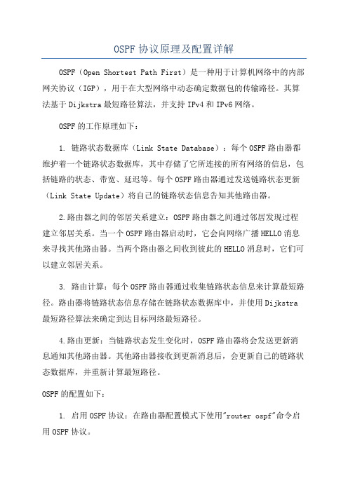
OSPF协议原理及配置详解OSPF(Open Shortest Path First)是一种用于计算机网络中的内部网关协议(IGP),用于在大型网络中动态确定数据包的传输路径。
其算法基于Dijkstra最短路径算法,并支持IPv4和IPv6网络。
OSPF的工作原理如下:1. 链路状态数据库(Link State Database):每个OSPF路由器都维护着一个链路状态数据库,其中存储了它所连接的所有网络的信息,包括链路的状态、带宽、延迟等。
每个OSPF路由器通过发送链路状态更新(Link State Update)将自己的链路状态信息告知其他路由器。
2.路由器之间的邻居关系建立:OSPF路由器之间通过邻居发现过程建立邻居关系。
当一个OSPF路由器启动时,它会向网络广播HELLO消息来寻找其他路由器。
当两个路由器之间收到彼此的HELLO消息时,它们可以建立邻居关系。
3. 路由计算:每个OSPF路由器通过收集链路状态信息来计算最短路径。
路由器将链路状态信息存储在链路状态数据库中,并使用Dijkstra 最短路径算法来确定到达目标网络最短路径。
4.路由更新:当链路状态发生变化时,OSPF路由器将会发送更新消息通知其他路由器。
其他路由器接收到更新消息后,会更新自己的链路状态数据库,并重新计算最短路径。
OSPF的配置如下:1. 启用OSPF协议:在路由器配置模式下使用"router ospf"命令启用OSPF协议。
2. 配置区域(Area):将网络划分为不同的区域。
在配置模式下使用"area <区域号> range <网络地址> <网络掩码>"命令将网络地址加入到区域中。
3. 配置邻居:使用"neighbor <邻居IP地址>"命令来配置OSPF邻居关系。
邻居IP地址可以手动配置或通过HELLO消息自动发现。
神州数码路由器及交换机配置命令
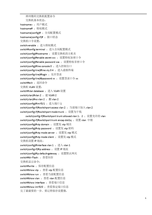
神州数码交换机配置命令交换机基本状态:hostname> ;用户模式hostname# ;特权模式hostname(config)# ;全局配置模式hostname(config-if)# ;接口状态交换机口令设置:switch>enable ;进入特权模式switch#config terminal ;进入全局配置模式switch(config)#hostname ;设置交换机的主机名switch(config)#enable secret xxx ;设置特权加密口令switch(config)#enable password xxa ;设置特权非密口令switch(config)#line console 0 ;进入控制台口switch(config-line)#line vty 0 4 ;进入虚拟终端switch(config-line)#login ;允许登录switch(config-line)#password xx ;设置登录口令xxswitch#exit ;返回命令交换机VLAN设置:switch#vlan database ;进入VLAN设置switch(vlan)#vlan 2 ;建VLAN 2switch(vlan)#no vlan 2 ;删vlan 2switch(config)#int f0/1 ;进入端口1switch(config-if)#switchport access vlan 2 ;当前端口加入vlan 2switch(config-if)#switchport mode trunk ;设置为干线switch(config-if)#switchport trunk allowed vlan 1,2 ;设置允许的vlan switch(config-if)#switchport trunk encap dot1q ;设置vlan 中继switch(config)#vtp domain ;设置发vtp域名switch(config)#vtp password ;设置发vtp密码switch(config)#vtp mode server ;设置发vtp模式switch(config)#vtp mode client ;设置发vtp模式交换机设置IP地址:switch(config)#interface vlan 1 ;进入vlan 1switch(config-if)#ip address ;设置IP地址switch(config)#ip default-gateway ;设置默认网关switch#dir Flash: ;查看闪存交换机显示命令:switch#write ;保存配置信息switch#show vtp ;查看vtp配置信息switch#show run ;查看当前配置信息switch#show vlan ;查看vlan配置信息switch#show interface ;查看端口信息switch#show int f0/0 ;查看指定端口信息完了最最要的一步。
神州数码路由交换配置命令(全)
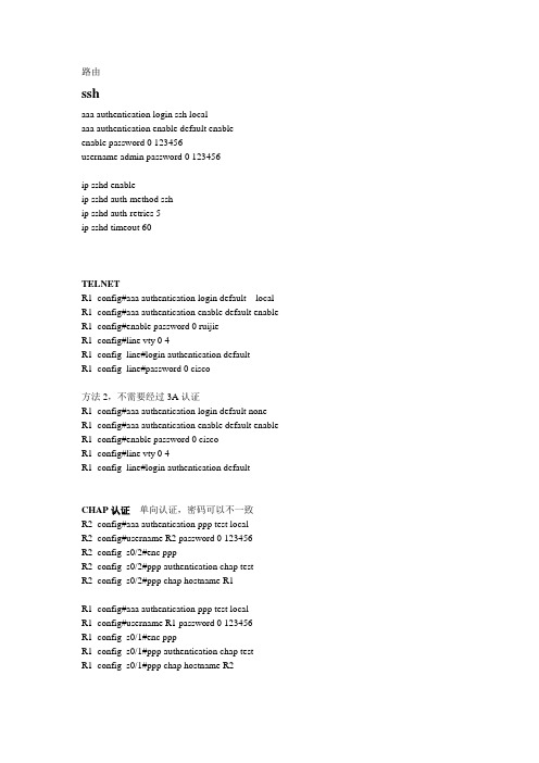
路由sshaaa authentication login ssh localaaa authentication enable default enableenable password 0 123456username admin password 0 123456ip sshd enableip sshd auth-method sship sshd auth-retries 5ip sshd timeout 60TELNETR1_config#aaa authentication login default local R1_config#aaa authentication enable default enable R1_config#enable password 0 ruijieR1_config#line vty 0 4R1_config_line#login authentication defaultR1_config_line#password 0 cisco方法2,不需要经过3A认证R1_config#aaa authentication login default noneR1_config#aaa authentication enable default enable R1_config#enable password 0 ciscoR1_config#line vty 0 4R1_config_line#login authentication defaultCHAP认证单向认证,密码可以不一致R2_config#aaa authentication ppp test localR2_config#username R2 password 0 123456R2_config_s0/2#enc pppR2_config_s0/2#ppp authentication chap testR2_config_s0/2#ppp chap hostname R1R1_config#aaa authentication ppp test localR1_config#username R1 password 0 123456R1_config_s0/1#enc pppR1_config_s0/1#ppp authentication chap testR1_config_s0/1#ppp chap hostname R2pap认证双向认证,密码要求一致R2_config#aaa authentication ppp test localR2_config#username R2 password 0 123456R2_config_s0/2#enc pppR2_config_s0/2#ppp authentication pap testR2_config_s0/2#ppp pap sent-username R1 password 123456R1_config#aaa authentication ppp test localR1_config#username R1 password 0 123456R1_config_s0/1#enc pppR1_config_s0/1#ppp authentication pap testR1_config_s0/1#ppp pap sent-username R2 password 123456FRRouter-A_config_s1/1#encapsulation frame-relay !封装帧中继协议Router-A_config_s1/1#frame-relay local-dlci 17 !设置本地DLCI 号Router-A_config_s1/1# frame-relay intf-type dce !配置FR的DCERouter-A_config_s1/1# frame-relay map 192.168.1.2 pvc 17 broadcast !配置DLCI 与对端IP的映射VrrpInt g0/4vrrp 1 associate 192.168.20.254 255.255.255.0vrrp 1 priority 120 设置优先级,为主vrrp 1 preempt 开启抢占vrrp 1 track interface Serial0/1 30 追踪上行接口,防止上行接口DOWN了,自动降低优先级Int g0/6vrrp 1 associate 192.168.20.254 255.255.255.0vrrp 1 priority 100 设置优先级,为备,默认为100vrrp 1 preempt 开启抢占vrrp 1 track interface Serial0/2 30 追踪上行接口,防止上行接口DOWN了,自动降低优先级RIP 验证,只有V2支持验证interface Serial0/2 接口起验证和配密码ip rip authentication simpleip rip password 123456RIP改单播router ripnei 192.168.1.1RIP定时器router riptimers update 10 更新时间timers exipire 30 失效时间timers hosddown 50 抑制时间ospfrouter os 1net 192.168.1.0 255.255.255.0 ar 0 不能写32位掩码OSPF 虚链路ROUTER OS 2 进程起用AR 1 VI 2.2.2.2 对方ROUTER-IDOSPF 汇总ROUTER OS 2 进程起用ar 0 range 192.168.0.0 255.255.252.0OSPF 验证ROUTER OS 2 明文AR 0 AUTHEN SP 进程给需要验证的区域启用验证INT S0/1IP OS passw 123456 接口配置密码密文router os 2ar 0 authen meint s0/1ip os me 1 md5 123456bgprouter bgp 100no synchronization bgp全互联必须要关闭同步检查nei 192.168.12.1 remot 200 与AS外部路由建立邻居nei 2.2.2.2 remot 100 与AS内部路由建立邻居nei 2.2.2.2 up lo0 改更新接口为环回接口nei 2.2.2.2 next-hop-self 改下一跳为自己net 2.2.2.0 通告路由表里面有的路由ACL路由上面的ACL要写子网掩码,不能写反掩码!!!!!基于时间的ACLtime-range acl 定义一个时间范围periodic weekdays 09:00 to 12:00periodic weekdays 14:00 to 17:00IP access-list extended time 写一个基于时间的acl,调用时间段deny ip 192.168.10.0 255.255.255.0 any time-range aclpermit ip any anyint g0/4 应用到接口ip access-group time inint g0/6ip access-group time in静态NATip route 0.0.0.0 0.0.0.0 192.168.12.2ip nat inside source static 192.168.10.10 192.168.12.1int g0/6ip nat inints0/1ip nat outNAPTip access-list standard NAT 定义要转换的IP网段permit 192.168.10.0 255.255.255.0ip nat pool NAT 192.168.23.10 192.168.23.20 255.255.255.0 创建转换的IP地址池ip nat inside source list NAT pool NAT overload 关联要转换的IP网段和地址池ip route default 192.168.23.3 写一条缺省路由,下一跳为出口网关的下一跳router rip 如果跑路由协议,要把缺省重分发到动态路由redistribute staticinterface Serial0/1 运用到内网接口ip nat insideinterface Serial0/2 运用到外网接口ip nat outsideroute-mapip acce sta acl 定义要匹配的流量per 192.168.20.0 255.255.255.0route-map SHENMA 10 permitma ip add acl 调用ACLset ip next-hop 192.168.12.1 改下一跳int g0/3ip po route-map SHENMA 定义到原接口DHCP给路由接口分配IP,不能是S口!!!R1ip dhcpd enableip dhcpd pool 1network 192.168.12.0 255.255.255.0range 192.168.12.10 192.168.12.20R2interface GigaEthernet0/6ip address dhcp给PC分配IP,底层网络要起路由互通!!!!实验全网起了RIP协议R1ip dhcpd enableip dhcpd pool 2network 192.168.1.0 255.255.255.0range 192.168.1.10 192.168.1.20default-router 192.168.1.1R2ip dhcpd enable 要开启DHCP服务!interface GigaEthernet0/4ip address 192.168.1.1 255.255.255.0ip helper-address 192.168.12.2 设置DHCP服务器IPVPN (GRE)int t0ip add 172.168.10.1 255.255.255.0 给T0配IPt so s0/2 源,路由的出接口t de 192.168.23.3 目的,对端的出接口IP,注意,要可达t key 123456 T0口密码,两端要一致exitip route 192.168.20.0 255.255.255.0 t0 用T0口写一条要到达网段的静态路由int t0ip add 172.168.10.3 255.255.255.0t so s0/1t de 192.168.12.1t key 123456exitip route 192.168.10.0 255.255.255.0 t0VPN (IPSEC)R1crypto ipsec transform-set SHENMA 设置转换集transform-type esp-des esp-md5-hmac 转换集的加密方式ip access-list extended 100 匹配感兴趣流permit ip 192.168.10.0 255.255.255.0 192.168.20.0 255.255.255.0crypto map HAN 10 ipsec-isakmpset peer 192.168.23.3 设置对等体set transform-set SHENMA 关联转换集match address 100 关联感兴趣流interface Serial0/2 进接口调用crypto map HANR3crypto ipsec transform-set SHENMA 设置转换集transform-type esp-des esp-md5-hmac 转换集的加密方式,两端要一致ip access-list extended 100 匹配感兴趣流permit ip 192.168.20.0 255.255.255.0 192.168.10.0 255.255.255.0crypto map HAN 10 ipsec-isakmpset peer 192.168.12.1 设置对等体set transform-set SHENMA 关联转换集match address 100 关联感兴趣流interface Serial0/1 进接口调用crypto map HANVPN (IKE)crypto isakmp key SHENMA 192.168.23.3 255.255.255.0 设置公共用密钥crypto isakmp policy 10 设置IKE策略hash md5au preenc desgroup 1lifetime 86400crypto ipsec transform-set SHENMA 设置转换集transform-type esp-Des esp-Md5-hmacip access-list extended 100 匹配感兴趣流permit ip 192.168.10.0 255.255.255.0 192.168.30.0 255.255.255.0crypto map SHENMA 10 ipsec-isakmp 设置IPSEC加密映射set peer 192.168.23.3set transform-set SHENMAmatch address 100int s0/2 调用到接口crypto map SHENMAQOSint g0/4ip add 192.168.10.1 255.255.255.0no shutip add 192.168.20.1 255.255.255.0no shutint s0/1ip add 192.168.12.1 255.255.255.0phy spe 64000no shutip route 0.0.0.0 0.0.0.0 192.168.12.2ip access-list ex 1 定义ACL抓取流量permit ip 192.168.10.0 255.255.255.0 2.2.2.0 255.255.255.0ip access-list ex 2permit ip 192.168.20.0 255.255.255.0 2.2.2.0 255.255.255.0priority 1 protocol ip high list 1 写一个IP协议的优先列表,调用ACL 1里面的地址,级别为HIGHpriority 1 protocol ip low list 2 写一个IP协议的优先列表,调用ACL 2里面的地址,级别为LOWint s0/1 进接口调用priority 1交换banner motd 系统登录标题telnettelnet-server enable 开启TELNETtelnet-server max-connection 16 最大连接数sshusername ssh password 0 123456ssh-server enable 开启SSHssh-server timeout 60 连接超时时间ssh-server max-connection 16 最大连接数ssh-server authentication-retries 5 重连次数ssh-server host-key create rsa 创建新的主机密钥1,首先要给所有的VLAN配上IPINT VLAN 10IP ADD 192.168.10.1 255.255.255.0NO SHUT2,创建一个VRRP组ROUTER VRRP 10VIRTUAL-IP 192.168.10.254 给虚拟IPINT VLAN 10 关联VLANPRIORITY 120 给优先级(默认100)ENABLE 激活STPSW1spanning-tree 开启STPspanning-tree mode mstp 改为MSTP模式spanning-tree mst configurtaion 配置域name shenma域名revision-level 3 修正级别instance 1 vlan10;20 在实例里面关联VLANinstance2 vlan30;40exitspanning-tree mst 1priority 4096 给实例配置优先级,越小的级别越高spanning-tree mst 2 priority 8192SW2spanning-tree 开启STPspanning-tree mode mstp 改为MSTP模式spanning-tree mst configurtaion 配置域name shenma域名revision-level 3 修正级别instance 1 vlan10;20 在实例里面关联VLANinstance2 vlan30;40exitspanning-tree mst 1priority 8192 给实例配置优先级,越小的级别越高spanning-tree mst 2 priority 4096SW21spanning-tree 开启STPspanning-tree mode mstp 改为MSTP模式spanning-tree mst configurtaion 配置域name shenma域名revision-level 3 修正级别instance 1 vlan10;20 在实例里面关联VLANinstance2 vlan30;40AM端口安全am enableint e1/0/1am portam mac-ip-pool 0000.1111.2222 192.168.10.1端口镜像monitor session 1 source int e1/0/1 bothmonitor session 1 destination int e1/0/15RIPRouter ripNet 192.168.1.0/24Router os 1Net 192.168.1.0 0.0.0.255 ar 0AclFirewall enableIp access-list ex 100Per ip 192.168.1.0 0.0.0.255 192.168.2.0 0.0.0.255单臂路由R1int g0/5no shutinterface GigaEthernet0/5.1encapsulation dot1Q 100ip address 192.168.10.1 255.255.255.0interface GigaEthernet0/5.2encapsulation dot1Q 200ip address 192.168.20.1 255.255.255.0interface GigaEthernet0/5.3encapsulation dot1Q 300ip address 192.168.30.1 255.255.255.0SW1vlan 100\sw int e1/0/1-2vlan 200sw int e1/0/3-4vlan 300sw int e1/0/5-6int e1/0/20sw mo trsw tr all vlan all端口聚合PORT-GROUP 1 创建一个组INT E1/0/17-18 聚合端口要设置为TRUNKSW MO TRSW TR ALL VLAN ALLPORT-GROUP 1 MO ON 设置聚合端口的模式为自动匹配EXITINT PORT-CHANNAL 1 进入聚合端口配置模式,也要设置为TRUNK SW MO TRSW TR ALL VLAN ALLEXITdhcpSERV DHCP 开启DHCP服务IP DHCP POOL VLAN10 创建地址池NETW 192.168.10.0 255.255.255.0def 192.168.10.1le 2dns 8.8.8.8ip dhcp ex 192.168.10.1 192.168.10.10 排除地址范围dhcp 中继serv dhcpip for udp bootint vlan 10ip he 192.168.12.2dhcp snoopingserv dhcp 开启DHCP服务ip dhcp snooping enable 开启DHCP SNOOPING 功能ip dhcp snooping binding enable 开启SNOOPING 绑定功能int e1/0/20ip dhcp snooping trust 设置接口为信任接口,一般是与服务器相连的接口int e1/0/1ip dhcp snooping binding user-control 设置端口自动绑定获取DHCP的地址设置端口手动绑定MAC,VLAN,IP,端口信息(全局模式)ip dhcp snooping binding user 00-11-22-33-44-55 address 192.168.22.22 vlan 1 int e1/0/5ipv66 to 4greipv6 unicast-routing 允许单播路由interface Tunnel0ipv6 enable 开启IPV6ipv6 address 2001:23::1/64tunnel source 192.168.12.1 本端接口地址tunnel destination 192.168.12.2 对端接口地址tunnel mode gre ip 隧道模式改为GREtunnel key 123456 隧道密码,两端一致ipv6 route 3::/64 Tunnel0 写一条下一跳为TUNNEL 0的IPV6静态,不能写默认静态natInternet(config)#ip route 0.0.0.0 0.0.0.0 fa0/1 ipv4网络要可达NA T-PT(config)#ip route 0.0.0.0 0.0.0.0 fa0/1NA T-PT(config)#ipv6 nat prefix 2001:db8:feed::/96 设置一个全局NAT前缀,掩码必须96位NA T-PT(config)#ipv6 nat v4v6 source 10.10.10.2 2001:db8:feed::2 写4 TO 6 地址转换,需要到达的地址都要写, 不需要与本地同一网段NA T-PT(config)#ipv6 nat v4v6 source 192.168.1.10 2001:db8:feed::3NA T-PT(config)#ipv6 nat v6v4 source 2001:db8:cafe:ffff::2 10.10.20.5 写6 to 4 地址转换,需要到达的地址都要写,不需要与本地同一网段int g0/4 调用到接口,进出都要调用ipv6 natint g0/4ipv6 natpatipv4 网络要可达NA T-PT(config)#ipv6 nat prefix 2001:db8:feed::/96 设置一个全局NAT 前缀,掩码必须96位NA T-PT(config)#ipv6 nat v4v6 source 10.10.10.2 2001:db8:feed::2 写4 TO 6 地址转换,需要到达的地址都要写NA T-PT(config)#ipv6 nat v4v6 source 192.168.1.10 2001:db8:feed::3 不需要与本地同一网段NA T-PT(config)#ipv6 access-list cafe 把IPV6要转换的网段匹配出来NA T-PT(config-ipv6-acl)#permit ipv6 2001:db8:cafe::/48 anyNA T-PT(config-ipv6-acl)#exitNA T-PT(config)#ipv6 nat v6v4 pool ipv4 10.10.20.5 10.10.20.6 prefix-length 24 写一个6 TO 4 的NAT地址池,不需要已知网段NA T-PT(config)#ipv6 nat v6v4 source list cafe pool ipv4 overload 把要转换的网段与地址池关联int g0/4ipv6 natint g0/4ipv6 natripingipv6 router rip 100 全局创建RIP实例,名字为100exitinterface GigaEthernet0/4ipv6 enable 开启IPV6ipv6 address 2001::1/64ipv6 rip 100 enable 启动为100的实例需要宣告的接口要设置ospfv3ipv6 router ospf 1 全局创建ospf,进程为1 int g0/6ipv6 enableipv6 address 2001::1/64ipv6 ospf 1 area 0 宣告本接口为area 0 需要宣告的接口要设置。
神州数码多区域OSPF配置

五、 实验要求
配置表
Router-A
Router-B
S1/1(DCE) 192.168.1.1 S/1/0(DTE) 192.168.1.2 F0/0
F0/0
192.168.0.1 F0/0
192.168.2.1 E1/0
路由器 B 为 ABR
六、 实验步骤
第一步:参照实验三和上表配置各接口地址,并测试连通性 第二步:路由器 A 的配置 Router-A#conf Router-A_config#router ospf 100
第四步:路由器 C 的配置 Router-C#conf Router-C_config#router ospf 100 Router-C_config_ospf_100#network 192.168.2.0 255.255.255.0 area 0 Router-C_config_ospf_100#network 192.168.3.0 255.255.255.0 area 0 Router-C_config_ospf_100#^Z
九、 共同思考
1. 为什么必须有 area 0 存在? 2. 在路由器 A 和 C 宣告网段的时候有其他的方法吗?
十、 课后练习
请将地址改为 10.0.0.0/25 重复以上实验
十一、 相关命令详解
network area
将一个区域中几个网段定义成一个网络范围, no network 命令取消网络范围。 network network mask area area_id [ advertise | not-advertise ] [ no ] network network mask area area_id [ advertise | not-advertise ]
神州数码各实验配置注意文档

//重点:两个三层交换机之间可以通过Vlan 1 进行路由退出的命令的运用在神州数码的视图下是没有quit的命令的,但并不代表不能用quit,在大多数的视图下,都可以用quit命令退回上一级视图,当然用exit也可以,看个人喜好,但有视图也是例外的,例如:# spanning-tree mst configuration视图下就要用它专用的退出命令:abrotNAT配置:1、配置acl允许通过的网段;//一般用标准acl2、配置地址池;ip nat pool+名字+起始IP+终止IP+子网掩码3、配置nat转换那个网段;Ip nat inside source list +acl名字pool +地址池名字4、配置int接口和out接口;【接口试图】ip nat inside【接口试图】ip nat insideNAT server:# ip nat inside source static tcp + 服务的IP地址+ 服务端口+ 要转换成公网的IP地址+ 端口号在发布FTP的时候最好把21和20的都发布出去DNS一定要使用UDP服务路由器enable用户密码和时间配置:1、enable password 0/7(不验证和验证)+密码level+权限(默认不配置的时候是15)2、date(接下来按照指示配置就OK了)配置语言:1、路由器Chinese2、交换机language ChineseOSPF路由协议的配置:1、router id的配置,可以选择配置,配置的时候,要指向路由器接入的端口上的IP地址2、router ospf +数字(可以随意)network +使能的网段+子网掩码+area +区域号(ospf 分单区域和多区域两种,单区域的配置要注意每一个使能的网段后面的区域号都要一致,多区域配置两个区域相交的那路由器使能网段的时候要配置和对端相对应的区域号)3、ospf的虚连接配置(ospf的虚连接是只多个不能直接相连接的区域通过建立逻辑的上虚拟连接,建立邻居关系):area +本网段的区域号+ virtual-link + 相同区域对端的路由器的router id(虚连接链路的配置是运用在至少3个不同区域的ospf上,而且其中两个区域,分别和第三个区域连接)4、可以使用neighbor + 邻接路由的IP地址Ping命令有趣使用:问题:ping 1.0.0.1 可以学成ping 1.001 ,写成1.1也能ping通因为ping 的协议的编写时采用了IPV6的机制的,中间是出现连续两个0的情况的话,可以合并,可以可以不写。
OSPF配置步骤
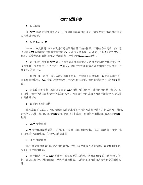
OSPF配置步骤1、设备配置将OSPF模块加载到网络设备上,并启用和配置路由协议,如果要使用指定路由协议,必须先进行配置。
2、配置Router IDRouter ID是使用OSPF协议进行通信的路由器节点的标识,在路由器中是唯一的,它必须在OSPF配置的初始步骤中显式定义,无法由系统选择。
可以使用任何32位的IPv4地址,通常是路由器接口的IP地址或者一个特定的Loopback地址。
3、定义网络网络是OSPF划分子网关系和路由器节点间连接点之间的逻辑连接。
定义网络时,需要指定一个“主机”IP地址,它将决定路由器节点间连续网络之间接口上启用OSPF的哪一方。
4、指定区域通过区域可以将路由器分割为一个或多个网络拓扑,以便管理路由条目的传输和收集。
OSPF协议分为区域型、网络型和主机型,每种类型运行不同的OSPF协议。
5、定义路由器节点路由器节点是OSPF网络中的分隔点,连接网络的另一部分。
在网络中,每一个路由器都是一个独立的实体,关联拥有不同或相同网络地址部分网络范围的路由器节点6、设置网络拓扑结构在网络设置完成后,可以按照自己的需求设置不同的网络拓扑结构,包括内网、外网、跨网等。
此外,还可以添加OSPF路由记录以控制流量,以及管理拓扑路由器之间的OSPF链路。
7、OSPF安全配置OSPF安全配置是重要的,可以防止“联盟”路由器的攻击,以及“源路由”攻击,让网络免受外界的威胁,保证网络的稳定性。
8、OSPF性能调整OSPF性能调整可以通过更改链路延迟,使用加权路由等方式来调整,以优化OSPF网络的通信效率和性能。
9、运行测试测试OSPF有效性并验证配置的正确性,以保证OSPF的正确性和安全性,测试过程中可以检查配置、状态和链接数据,以确保正确的路由决策和稳定的通信结果。
神州数码配置命令归纳(已更新)
第一部分交换机配置一、基础配置1、模式进入Switch>Switch>enSwitch#configSwitch(Config)#interface ethernet 0/22、配置交换机主机名命令:hostname <主机名>3、配置交换机IP地址Switch(Config)#interface vlan 1Switch(Config-If-Vlan1)#ip address 10.1.128.251 255.255.255.0Switch(Config-If-Vlan1)#no shut4、为交换机设置Telnet授权用户和口令:登录到Telnet的配置界面,需要输入正确的用户名和口令,否则交换机将拒绝该Telnet用户的访问。
该项措施是为了保护交换机免受非授权用户的非法操作。
若交换机没有设置授权Telnet用户,则任何用户都无法进入交换机的Telnet配置界面。
因此在允许Telnet方式配置管理交换机时,必须在Console的全局配置模式下使用命令username <username>privilege <privilege> [password (0 | 7) <password>]为交换机设置Telnet授权用户和口令并使用命令authentication line vty login local打开本地验证方式,其中privilege选项必须存在且为15。
例:Switch>enableSwitch#configSwitch(config)#username test privilege 15 password 0 testSwitch(config)#authentication line vty login localSwitch(Config)#telnet-user test password 0 testSwitch (Config)#telnet-server enable://启动远程服务功能5、配置允许Telnet管理交换机的地址限制(单独IP或IP地址段)(1)限制单个IP允许Telnet登录交换机switch(config)#authentication security ip 192.168.1.2(2)限制允许IP地址段Telnet登录交换机switch(config)#access-list 1 permit 192.168.1.0 0.0.0.255switch(config)#authentication ip access-class 1 in5、为交换机设置Web授权用户和口令:web-user <用户名>password {0|7} <密码>例:Switch(Config)#web-user admin password 0 digital6、设置系统日期和时钟:clock set <HH:MM:SS> <YYYY/MM/DD>7、设置退出特权用户配置模式超时时间exec timeout <minutes > //单位为分钟,取值范围为0~3008、保存配置:write9、显示系统当前的时钟:Switch#show clock10、指定登录用户的身份是管理级还是访问级Enable [level {visitor|admin} [<密码>]]11、指定登录配置模式的密码:Enable password level {visitor|admin}12、配置交换机的用户名密码:username admin privilege 15 password 0 admin00013、配置enable密码为ddd:enable password 0 ddd level 1514、配置登录时认证:authentication line vty login local15、设置端口的速率和双工模式(接口配置模式下)命令:speed-duplex {auto | force10-half | force10-full | force100-half | force100-full | {{force1g-half | force1g-full} [nonegotiate [master | slave]] } }no speed-duplex二、单交换机VLAN划分1、VLAN基本配置(1)新建VLAN:vlan <vlan-id>(2)命名VLAN:name <vlan-name>(3)为VLAN 分配交换机端口Switch(Config-If-Vlan1)#switchport interface Ethernet 0/2(4)设置Trunk 端口允许通过VLAN:Switch(Config-ethernet0/0/5)#switchport trunk allowed vlan 1;3;5-202、划分VLAN:(1)进入相应端口:Switch(config)#interface Ethernet 0/2(2)修改模式:Switch(Config-ethernet0/0/5)switchport mode access(3)划分VLAN:Switch(Config-ethernet0/0/5)#switchport access vlan 4三、跨交换机VLAN划分(两台交换机作相同操作)1、新建VLAN2、划分VLAN3、修改链路模式(1)进入相应端口:Switch(config)#interface Ethernet 0/1(2)修改模式:Switch(config-if)#switchport mode trunk四、VLAN间主机的通信1、新建VLAN2、划分VLAN3、修改链路模式(1)进入相应端口:Switch(config)#interface Ethernet 0/1(2)修改模式:Switch(config-if)#switchport mode trunk注意:如果是三层交换机,在修改模式先封装802.1协议:Switch(config-if)#switchport trunk encapsulation dot1q4、建立VLAN子接口(1)、进入VLAN接口模式:Switch(config)#interface vlan 2(2)、设置VLAN子接口地址:Switch(config-if)#ip address 192.168.0.1 255.255.255.0 (3)、打开端口:Switch(config-if)#no shutdown5、设置各主机IP地址、子网掩码、网关注意:(1)各主机IP地址应与其所在的VLAN在同一网段。
神州数码路由器实例配置
本地局域网互联(路由协议配置)任务一实验目的:1 掌握路由协议的配置方法;2 理解路由协议的工作过程和使用环境;3 掌握利用路由器连接本地局域网的方法;试验设备:1.DCR-1700或者DCR-2600 路由器一台2. DCRS-3926S交换机一台3. PC机,网线,CONSOLE 线实验拓扑:实验步骤:1.Router#deletethis file will be erased,are you sure?(y/n)y no such fileRouter#writeSaving current configuration...OK!Router#rebootDo you want to reboot the router(y/n)?yPlease wait.. //恢复出厂设置2.Router#show ip route //查看IP路由表Codes: C - connected, S - static, R - RIP, B - BGP, BC - BGP connectedD - DEIGRP, DEX - external DEIGRP, O - OSPF, OIA - OSPF inter areaON1 - OSPF NSSA external type 1, ON2 - OSPF NSSA external type 2OE1 - OSPF external type 1, OE2 - OSPF external type 2DHCP - DHCP typeVRF ID: 0 //没有路由表项3.Router#configRouter_config#interface fRouter_config#interface fastEthernet 0/0Router_config_f0/0#ip address 192.168.2.1 255.255.255.0Router_config_f0/0#exit Router_config#interface eRouter_config#interface ethernet 0/1Router_config_e0/1#ip address 192.168.1.1 255.255.255.0//设置路由器两个以太网接口IP地址4.VRF ID: 0C 192.168.1.0/24 is directly connected, Ethernet0/1 C 192.168.2.0/24 is directly con nected, FastEthernet0/0 //直通路由5.测试PC1与测试计算机的连同性。
神州数码交换机路由器常用命令操作
神州数码交换机常用命令操作交换机初始化Ctrl+B交换机恢复默认值SetdefaultwriteReload1.创建vlan、将端口指定为相应vlan、vlan分配IPVlan [编号] //创建vlan 例:vlan10Swi Int eth0/0/[编号-编号] //指定那些端口属于这个vlan 例:swi Int e0/0/1-10 int vlan [编号] //进入vlan接口例:int vlan 10 Ip add [IP地址] [子网掩码] //配置IP地址例:ip add 192.168.1.1 255.255.255.0创建私有vlan方法Vlan 10Private-vlan primary 指定为主vlanVlan 11Private-vlan community 指定为群体vlanVlan 12priate-vlan isolated 指定为隔离vlan创建关联:vlan 10Priate-vlan association [关联的vlan号] //主vlan关联群体vlan和隔离vlan 给各vlan指定相应端口结果:群体vlan和隔离vlan ping主vlan 通群体vlan内通;主vlan 内通;群体vlan间不通;隔离vlan内不通;2.配置远程管理(可通过setup配置)(1)交换机telnet远程管理telnet-server enable //开启telnet服务,默认以开启telnet-user [用户] password 0 [密码] //添加telnet管理用户(2)web服务管理Ip http sever //开启web服务,需手动开启Web-user [用户名] password 0 [密码] //添加web管理用户3.静态路由Ip route [目标地址段] [目标掩码] [下一跳IP/接口]Ip route 0.0.0.0 0.0.0.0 [下一跳IP/接口] //ip route 0.0.0.0 0.0.0.0 192.168.1.2 4.RIP协议路由以Vlan方法Router ripName[名称]Networkvlan[编号] //networkvlan10以IP方法Router ripName [名称]Network [ip段]5.ospf协议路由以Vlan方法Router ospf [ 编号] //默认编号是1Int vlan [vlan号] //int vlan 10 [区域号]默认为0,必须有Ip ospf enable area [区域号] //ip ospf enable area 0以IP方法Router ospf [ 编号]Router-id [ip地址]Network [自己的IP] [网关] area 0 //network 192.168.1.1/24 area 0 6.生成树协议1)Stp模式配置spanning-tree //启用生成树spanning-tree mode stp //设置生成树模式spanning-tree mst 0 priority 4096 //设置生成树交换机优先级2)mstp的配置spanning-treespanning-tree mst configurationname [名称]instance [实例号] vlan [编号]spanning-tree mst [实例号] priority 4096 //设置生成树交换机优先级spanning-tree mst [实例号] port-priority 16 //设置生成树端口优先级3)配置成快速启用端口Int e0/0/[编号-编号]Spanning-tree portfast7.链路聚合(手工)port-group [组号] //创建聚合组号int e0/0/[做链路的那几个端口号] //将端口加入聚合组port-group [组号] mode on8.链路聚合(LACP动态生成)port-group [组号]int e0/0/[做链路的那几个端口号](交换机A的配置)port-group [组号] mode active(交换机B的配置)port-group [组号] mode passive9.trunkInt e0/0/[端口]Sw mode trunk //设置为trunkSw trunk allowed vlan all //划分到所有vlan10.Mac地址和端口绑定(单个)Int e0/0/[端口]Sw port-securitySw port-security mac-address [mac地址]11.Mac地址和端口绑定(多个)Inte0/0/[端口]Sw port-securitySw port-security maximum [安全mac地址个数如:3]sw port-security mac-address [mac地址]sw port-security mac-address [mac地址]sw port-security mac-address [mac地址]12.Mac地址和端口绑定(动态学习)Int e0/0/[端口]Sw port-security maximumSw port-security maximum lockSw port-security maximum convert13.mac地址表绑定mac-address-table static address[mac地址]vlan[编号]inte0/0/[编号]//解释:让mac地址只能在指定vlan中的指定端口中使用,其他的都不能使用(未测试) 14. 端口安全1) int e0/0/1-10 //进入端口,只能在access口上配置2) switchport port-security //开启端口安全功能3) switchport port-security maximum 5 //配置端口安全最大连接数4) sw port-security violation shutdown //配置违例处理方式5).sw port-security mac-address [mac地址] //配置mac地址绑定15. 交换机端口镜像(将源端口数据复制到目标端口)1) monitor session 1 source interface fastEthernet 0/2 both //源端口、被镜像的端口2) monitor session 1 destiNation interface fastEthernet 0/3 //目标端口、镜像端口16.dhcp配置1)交换机做dhcp服务器配置Service dhcp //启用DHCP服务Ip dhcp pool [地址池名]Network-address [IP段如:192.168.1.0] [掩码数如:24]Lease[租用天数]Default-router[网关IP]Dns-server[DNS的IP]Ip dhcp excluded-address<开始地址><结束地址>//指定网段中不分配的IP地址2)Dhcp中继服务的配置Service dhcpIp forward-protocol udp bootps //配置DHCP中继转发port端口的UDP广播报文,默认67端口Int vlan [编号]或在接口上配置 //int e0/0/[编号]Ip help-address [服务器IP] //指定DHCP中继转发的UDP报文的目标地址17.ACL IP访问控制下面2条是开启ACLFirewall enable //开启包过滤功能Firewall default permit //设置默认动作为允许//定义标准访问控制列表 //定义访问列表Ip access-list standard test //在端口上应用列表Deny 192.168.1.100.00.0.0.0.255//禁止IP段访问Deny 192.168.200.11 0.0.0.0//禁止单个IP访问Denytcp192.168.200.00.0.0.255any-destinationd-port23//拒绝IP段telnet数据Permit192.168.1.100.00.0.0.0.255//允许IP段访问Deny192.168.200.110.0.0.0//允许IP访问//绑定ACL到各个端口Inte0/0/[端口]Ip access-group test in//验证方法Show access-group标准ACL实验1) access-list 1 deny 192.168.1.0 0.0.0.255 //拒绝访问的IP段2) access-list 1 permit 192.168.1.0 0.0.0.255 //允许的IP段3) //进入端口4) ip access-group 1 in //把控制列表1 配入端口,进入控制5) ip access-group 1 out //把控制列表1 配入端口,输出控制15. 扩展ACL实验1) access-list 101 deny tcp A.B.C.D 255.255.255.0 A.B.C.D 255.255.255.0 eq ftp(WWW)// 禁止前面个网段访问后面个网段的ftp或者WWW16. 交换机单向访问控制1) //使用标准ACL2) access-list 1 deny 192.168.1.0 0.0.0.2553) //进入端口4) ip access-group 1 in神州数码路由器常用命令操作路由器初始化:ctrl+breakNopassword路由器恢复默认值dirDel startup-configReboot1.进入端口给端口分配IPInt [端口]Ip add [ip] [子网掩码]No shuFC串口配置时钟频率Ph sp 640002.静态路由Ip route [目标地址段] [目标掩码] [下一跳IP/接口]Ip route 0.0.0.0 0.0.0.0 [下一跳IP/接口] //默认路由Ip route 0.0.0.0 0.0.0.0 [下一跳IP/接口] 10 //浮动路由3.RIP协议路由Router ripNetwork [ip段]4.ospf协议路由Router ospf [进程号]Router-id [ip地址]Network [自己的IP段] [子网掩码] area [区域号如:0]5.telnet开启方法1Aaa authen enable default lineAaa authen login default lineEnable passwd [密码]Line vty 0 4Password [密码]方法2Username [用户名] password [密码]Aaa authentication login [用户名] localLine vty 0 4Login authentication [刚刚那个用户名]6.web访问配置Username [用户] password 0 [密码] //添加用户Ip http webm-type[web配置方式] //选择方式.高级,典型,向导Ip http port[端口] //配置web端口7.ppp协议时钟频率physical-layer speed 64000封装PPP协议Int s0/[编号]Enc ppp //封装PPP协议单向验证(验证方式为PAP和CHAP)验证方Aaa authen ppp default localUsername [用户名] password [密码]Int s0/[编号]Enc pppPpp authen pap被验证方Aaa authen ppp default localInt s0/[编号]Enc pppPpp pap sen [用户名] passwd [密码]双向验证:9.hdlcInt s0/[编号]Enc hdlc //和PPP差不多,都在端口中配置10.dhcp配置Ip dhcp pool[地址池名]Network 192.168.2.0 255.255.255.0 //定义网络段Range 192.168.2.10 192.168.2.20 //定义地址范围Default-router [IP] //配置网关Dns-sever [ip] //配置NDS的IPLease [天数] //租用天数//退回配置模式(config)Ip dhcpd enable//开启dhcp11.Nat网络地址转换分为三种静态地址转换、动态地址转换、端口复用第一种1对1的网络地址转换,也叫静态地址转换,主要用于发布服务器(FTP/WEB/telnet)1)定义内外口在端口下输入ip nat inside ip nat outside2)配置地址转换:ip nat inside source static <服务器地址> <公网地址>ip nat inside source static tcp <服务器地址> 80 <公网地址> 80 发布WWW服务ip nat inside source static tcp <服务器地址> 20 <公网地址> 20 发布ftp服务ip nat inside source static tcp <服务器地址> 21 <公网地址> 21ip nat inside source static tcp <服务器地址> 23 <公网地址> 23 允许telnet远程登陆第二种多对多的网络地址转换,也叫动态地址转换1)定义内外口在端口下输入ip nat inside ip nat outside2)定义内网访问列表(标准)和外网的地址池定义内网访问列表:ip access-list standard <列表名>permit <vlan段> <反掩码> //定义允许转换的源地址范围定义外网的地址池:ip nat pool <地址池名> <外网开始地址> <外网结束地址> netmask <子网掩码> 3)配置地址转换:ip nat inside source list <列表名> pool <地址池名> overload第三种多对一的网络地址转换,也叫端口复用(natp)1)定义内外口在端口下输入ip nat inside ip nat outside2)定义内网访问列表定义内网访问列表:ip access-list standard <列表名>permit <vlan段> <反掩码>3)配置地址转换:ip nat inside source list <列表名> interface <外网接口编号> overload12.vpn(L2TP/PPTP)的配置//A到B的数据传输实例ROUTER-A的配置Intvirtual-tunnel0Ipadd172.16.1.2255.255.255.0***********************Pppchappassword[密码]//退回配置模式(config)VpdnenableVpdn-group0Request-dialinInitiate-toip192.168.1.2priority1Protocol12tp//退回配置模式(config)Iproute192.168.2.0255.255.255.0virtual-tunel0ROUTER-B的配置13、路由重分布redistribute static 重分布静态路由default-information originate 重分布默认路由redistribute connect 重分布直连网段redistribute rip 重分布RIP路由redistribute ospf <进程号> 重分布OSPF路由default-metric [权值] 设置路由权值14、策略路由1)定义内网访问列表:ip access-list standard <列表名>permit <vlan段> <反掩码>2)定义路由图route-map <图名> <图号1> permit/denymatch ip address <列表名>set ip next-hop <ip-address> 设置下一跳地址或 set interface fastethernet < > 设置出口route-map <图名> <图号2> permit/denymatch ip address <列表名>set ip next-hop <ip-address> 设置下一跳地址或 set interface fastethernet < > 设置出口3)在指定路由器的入口上应用路由图Router(config-if)#ip policy route-map <图名>15、Rip 认证:在端口上进行认证(要求在两台设备的路由端口配置)RIP版本1不支持认证。
神州数码配置命令
Telnet远程Shell管理•设置交换机IP地址–Switch(config)#interface vlan 1–Switch(config-If-Vlan1)#ip address 10.1.1.1 255.255.255.0–Switch(config-If-Vlan1)#no shutdown•交换机设置Telnet授权用户和口令;若交换机没有设置授权Telnet用户,则任何用户都无法进入交换机的CLI配置界面。
–Switch(config)#telnet-user test password 0 testHTTP远程图形管理•设置交换机IP地址–Switch(config)#interface vlan 1–Switch(config-If-Vlan1)#ip address 10.1.1.1 255.255.255.0–Switch(config-If-Vlan1)#no shutdown•交换机启动HTTP Server功能–Switch(config)#ip http server•交换机设置Web授权用户和口令;若交换机没有设置授权Web用户,则任何用户都无法进入交换机的Web配置界面。
–Switch(config)#web-user test password 0 testSSH配置•Switch(Config)#ssh-user test password 0 test•Switch(Config)#ssh-server enableVLAN的基本配置•划分VLAN 100和VLAN 200,并加入端口;–Switch(Config)#vlan 100–Switch(Config-Vlan100)#switchport interface e0/0/1-5–Switch(Config)#vlan 200–Switch(Config-Vlan200)#switchport interface e0/0/6-10•配置0/0/24端口为级联端口–Switch(Config)#interface ethernet 0/0/24–Switch(Config-ethernet0/0/24)#switchport mode trunk–switchport trunk allowed vlan 100;200–/#Trunk端口缺省允许通过所有VLAN;用户可以通过上述命令设置哪些VLAN 的流量可以通过Trunk口,没有包含的VLAN流量则被禁止。
- 1、下载文档前请自行甄别文档内容的完整性,平台不提供额外的编辑、内容补充、找答案等附加服务。
- 2、"仅部分预览"的文档,不可在线预览部分如存在完整性等问题,可反馈申请退款(可完整预览的文档不适用该条件!)。
- 3、如文档侵犯您的权益,请联系客服反馈,我们会尽快为您处理(人工客服工作时间:9:00-18:30)。
IPv4路由典型配置-OSPF
一、组网说明
网络中的三台设备运行OSPF协议,接口地址如下图。
配置单区OSPF协议确保三台设备之间可以互访。
二、组网图
三、配置步骤
SW 1的配置
#配置三层接口地址及Loopback接口地址
switch(config)#interface vlan10
switch(config-If-Vlan10)#ip address192.168.10.1 255.255.255.0
switch(config-If-Vlan10)#exit
switch(config)#interface vlan20
switch(config-If-Vlan20)#ip address192.168.20.1 255.255.255.0
switch(config-If-Vlan20)#exit
switch(config)#interface loopback 1
switch(config-If-loopback1)#ip address10.1.1.1 255.255.255.255
switch(config-If-loopback1)#exit
#配置OSPF协议,宣告设备所连的网段
switch(config)#router ospf
switch(config-router)#router-id10.1.1.1
switch(config-router)#nework192.168.10.1/24 area 0
switch(config-router)#nework192.168.20.1/24 area 0
switch(config-router)#exit
SW 2的配置
#配置三层接口地址及Loopback接口地址
switch(config)#interface vlan10
switch(config-If-Vlan10)#ip address192.168.10.2 255.255.255.0 switch(config-If-Vlan10)#exit
switch(config)#interface vlan30
switch(config-If-Vlan30)#ip address192.168.30.1 255.255.255.0 switch(config-If-Vlan30)#exit
switch(config)#interface loopback 1
switch(config-If-loopback1)#ip address10.1.1.2 255.255.255.255 switch(config-If-loopback1)#exit
#配置OSPF协议,宣告设备所连的网段
switch(config)#router ospf
switch(config-router)#router-id10.1.1.2
switch(config-router)#nework192.168.10.1/24 area 0
switch(config-router)#nework192.168.30.1/24 area 0
switch(config-router)#exit
SW 3的配置
#配置三层接口地址及Loopback接口地址
switch(config)#interface vlan20
switch(config-If-Vlan20)#ip address192.168.20.2 255.255.255.0 switch(config-If-Vlan20)#exit
switch(config)#interface vlan30
switch(config-If-Vlan30)#ip address192.168.30.2 255.255.255.0 switch(config-If-Vlan30)#exit
switch(config)#interface loopback 1
switch(config-If-loopback1)#ip address10.1.1.3 255.255.255.255 switch(config-If-loopback1)#exit
#配置OSPF协议,宣告设备所连的网段
switch(config)#router ospf
switch(config-router)#router-id10.1.1.3
switch(config-router)#nework192.168.20.1/24 area 0
switch(config-router)#nework192.168.30.1/24 area 0
switch(config-router)#exit
四、注意事项
无
本手册版权为DCN所有,欢迎传阅
如果有任何意见或建议,请联系 400-810-9119。