ZW43使用说明书
ZW43A-12型户外真空断路器
ZW43A-12型户外真空断路器
王靖宇
【期刊名称】《电力系统装备》
【年(卷),期】2005(000)010
【摘要】由华仪电器集团有限公司生产的ZW43A-12型户外真空断路器是额定电压12kV、三相交流50Hz的户外开关设备,主要用于开断、关合配网系统的负载电流、过载电流及短路电流,可用于变电站、工矿企业及城、农网作保护和控制之用,特别适用于操作频繁的场所和城网自动化配电网络。
【总页数】1页(P70)
【作者】王靖宇
【作者单位】无
【正文语种】中文
【中图分类】TM561.2
【相关文献】
1.ZW7-40.5型户外真空断路器运行故障及处理 [J], 赵晓娜
2.12kV户外高压真空断路器检修工艺规程研究 [J], 江厚华
3.BVAC.N99型真空断路器替代TDZ1型空气断路器电气接口改进方案 [J], 王泰杰;黄正良
4.ZW7-40.5型户外真空断路器配3AF操动机构的尝试 [J], 赵自林
5.ZW□—10/630—16型户外高压真空断路器 [J], 邹积岩;何俊佳;张汉明;陈轩恕
因版权原因,仅展示原文概要,查看原文内容请购买。
施耐德ZWD414B D415 D416 D433B D432B D433C综合电量变送器使用说明书

ZWD414B/D415/D416/D433B/D432B/D433C 综合电量变送器使用说明书(版本号 V4.1)本文档内容适用于以下型号:ZWD414B—单相综合电量变送器ZWD415—单相交直流电量变送器ZWD416—单相交直流电量变送器(带量程换挡)ZWD433B—三相综合电量变送器ZWD432B—三相综合电量变送器(谐波分析型)ZWD433C—多路综合电量变送器目录1. 产品选型说明 (1)2. 主要技术参数 (6)3. 产品外观、按键及显示窗口 (11)4. 使用前的准备 (12)4.1 测试原理 (12)4.2 安装使用流程 (12)4.3 开机信息说明 (12)4.4 注意事项 (13)5. 基本参数设置 (13)5.1 参数设置 (13)5.2 设置操作示例 (14)6. 使用接线图 (15)7. 串口通讯 (22)8. 扩展功能 (25)8.1 继电器输出功能 (25)8.2 开关量输入功能 (26)8.3 开关量输出功能 (27)9. 装箱清单 (28)10. 注意事项及产品维护 (28)附录1关于Z W D415外置分流器补充说明 (30)1.产品选型说明:表1 产品选型说明表1-1 ZWD414B/D433B功能第 1 页表1-2 ZWD415/ZWD416功能第 2 页表1-3 ZWD432B功能第 3 页表1-4 ZWD433C功能第 4 页表2 其他参数:订货须知:用户在订货前,请确认以下项目:1. 测试参数的范围满足订货产品的量程要求;其它测试范围必须订货时声明。
2. 工作电源:AC (85~265)V,(45~65)Hz;DC (125~250)V;其它要求必须订货声明。
3. 通讯串口默认RS485,MODBUS规约,如需RS232必须订货声明。
4. 扩展功能为选项,非标准配置;用户订货时必需声明。
5. 特制产品测量量程请参照产品标牌,其它特别声明的技术要求或使用要求。
zwk系列微机控制热变形维卡试验机使用书说明书
Edgewiae Position
第 1 章. 产品信息…………………………………………………………………………….4 1.1. 概述………………………………………………………………………………………4 1.2. 功能………………………………………………………………………………………4 1.3. 主要特点…………………………………………………………………………………4 1.4. 执行的标准………………………………………………………………………………4 1.5. 主要技术参数……………………………………………………………………………5
本手册版权所有深圳市新三思材料检测有限公司;本手册的任何部分未经深圳市新三 思材料检测有限公司书面许可,不得以任何方式影印、复印或翻译成其它语言。
本书中带有 “★”的地方,请您特别注意并仔细阅读。
随机文件:
随机装有如下文件:
1、 《使用说明书》
一份
2、 《产品出厂装箱单》 一份
3、 《产品保修卡》
二份
ZWK 系列微机控制热变形维卡试验机使用书说明书
声明
感谢您选择新三思试验机!您能成为我们的客户是我们莫大的荣幸。本公司不仅给 您提供质量优异的产品,而且将为您提供满意的服务!为了您能更熟练地使用本试验机, 我们随机配备了说明书。
本手册主要介绍本设备有关的结构原理、设备安装、操作方法以及安全注意事项等方 面的知识。
ZWV二代变频空压机使用手册

ZW43使用说明书资料

ZW43-12型户外高压真空断路器使用说明书浙江X X电气有限公司1主要用途ZW43-12型户外高压真空断路器(以下简称断路器)是额定电压为12KV,50HZ三相交流的户外配电设备。
主要用于配电网开断,关合电力系统中的负荷电流,过载电流及短路电流。
适用于变电站及工矿企业配电系统中做保护和控制,适用于农村电网及频繁操作的场所,特别适用于城亡,农网改造的需要。
本安装使用说明书规定了断路器的主要技术参数,产品结构,以及操作,安装使用维护的原理和方法等内容。
1.2 引用标准GB19841989《交流高压断路器》GB/T110221999《高压开关设备和控制设备标准的共用技术要求》GB311.11997《高压输变电设备的绝缘配合:高压试验技术》GB33091989《高压开关设备在常温下的机械试验》DL/T4032000《12~40.5KV高压真空断路器订货技术条件》1.3 使用的环境条件1.3.1海拔高度不超过2000m;1.3.2周围空气温度不超过:-45℃~+40℃;1.3.3风速不大于35m/s;1.3.4污秽等级:Ⅳ1.3.5安装场所:无易燃,爆炸危险,化学腐蚀的场所;1.3.6地震强度不超过8度1.4 主要特点1.4.1 断路器采用三相支柱式结构,具有开断性能稳定可靠,无燃烧和爆炸危险,免维护,体积小,重量轻和使用寿命长等特点。
1.4.2断路器采用全封闭结构,密封性能好,有助于提高防潮,防凝露性能特别适应于严寒或潮湿地区使用。
1.4.3三相支柱及电流互感器采用进口户外环氧树脂固体绝缘,具有耐高低温,耐紫外线,耐老化的特点。
1.4.4操作机构采用小型化弹簧操作机构,分合闸能耗低;机构传动采用直动传输方式,分合闸部件少,可靠性高。
操作机构置于密封的机构箱中,解决了机构锈蚀的问题,提高了机构的可靠性。
1.4.5断路器的分,合闸操作可采用手动或电动操作及远方操作。
可与控制器配套实现配电自动化,也可以与重合器配合组成重合器/1.4.6断路器可以装设二相或三相CT,供过电流自动脱扣保护和智能控制器进行信息分析。
伯马德浪涌预期阀型号435使用说明书

Installation and operationManualBermad Surge Anticipation ValveModel No 435Valve DescriptionThe model No 435 Surge Anticipation Valve is an off line , hydraulically operated diaphragm actuated control valve. The valve sensing the line pressure, opens in response to the pressure drop associated with the rapid pump stoppage. The pre opened valve dissipates the returning high pressure wave, eliminating the surge.The model 435 closes drip tight as quickly as the relief feature allows, while preventing closing surge.The valve also acts as a quick pressure relief valve responding to sudden increases in the line pressure.Valve Technical DetailsThe following details relates to the technical specifications of the valve and components.Basic Valve Type : Bermad 400 series globe style hydraulic single chamber valve Valve rating : 1600 Kpa max pressurepressureopening40KpaminimumValve material : Epoxy coated cast iron with rubber diaphragmValve Model : Model No IR-X-ASTE-435Low Pressure Pilot : #2 Bermad pilot with grub screw removed on port Z Pressure rating : 1600Kpa maximum pressureSpring range : 100-1250 Kpa adjustmentRotation of bolt : One rotation = 190Kpa approxHigh Pressure Pilot : #3 Bermad pilotPressure rating : 1600Kpa maximum pressureSpring range : 100-1250 Kpa adjustmentRotation of bolt : One rotation = 190Kpa approxTubing : 3/8” copper with brass fittings (HP nylon optional)Gauge : 0-1600Kpa dual scale 65mm liquid filled ¼” BSP inletInstallation and SizingWe recommend the following installation considerations to ensure correct operation of the valve.1. Valve size. We recommend that the valve size be discussed with theBermad company for suitability of valve size for the application. In manyinstances there may be more than 1 valve in the operation should there bemore than 1 pump in the network.2. Installation of valve position. The best mode of installation is to have thevalve horizontal, as it makes maintenance of the valve simpler and avoids any air pockets in the valve. Should the valve be fitted vertically, we suggestmodifications to the valve cover to ensure best operation. We rotate thecover so tha the connection to the cover is at the highest location.3. Installation of valve on pipeline. The valve should be installed inaccordance with the irrigation designer and Bermad valve recommendations.This will usually be located at the or close to the pump station after the check valves of the pump. The valves are usually mounted on a tee piece off themain pipeline itself.4. Installation of associated valves. We recommend that a form of isolatingvalve (gate or butterfly) be mounted directly before the surge anticipationvalve for reasons of setting or maintenance. In addition to this werecommend the use of a an anti-slam air valve be mounted in the mainpipeline to ensure there is no possibility of vacuum holding the valve closedon the down-surge. Again the irrigation designer with Bermad canrecommend suitable valve sizing for the application. Bermad model C30-SPor Fox-AS should be considered.5. Discharge piping from surge valve. The size of the pipe leaving the surgevalve is critical to the safe operation of the valve. As the system velocity canbe as high as 12-15m/s velocity, we suggest the pipe size is considerablylarger than the valve size (in order to reduce system velocity) and the use ofbends and elbows be kept to a minimum in order to reduce thrust on thepipework. The pipe must go to atmosphere and allow the surge to relievewithout back pressure. If running pipe down a river bank, vacuum breakers(such as Bermad model 50mm C10) must be installed in order to avoid pipecollapsure. This will also cause the valve to slam close which will alsogenerate a secondary pipe surge.Setting of the valve for operationWe suggest if there is any doubt in the operation or setting of the valve, you first contact your irrigation supplier or Bermad for assistance.1. Ensure the pipeline is fully charged and the pipe is full as in normal operation.2. Ensure you have a copy of the pump curve to identify the operation of thepumps.3. Prior to opening the butterfly valve ensure the following is done to the Bermad435 valve.∙Open valve 1 and close valve 2∙Turn adjustment bolt on low pressure pilot 2 anti-clockwise fully until there is no tension on the spring.∙Turn adjustment bolt clockwise fully.∙Turn needle valve on pilot #3 fully clockwise and tighten locknut.∙Turn needle valve on pilot #2 clockwise fully and re-open ¼ of a turn.4. Open the butterfly very slowly a small amount 1/8 turn to apply pressure tothe valve. When the pressure rises above 4m, the valve will open and as the chamber fills, the valve will start to close as water enters the control chamber.We suggest you carefully loosen a brass fitting on the copper tube to releasethe air from the top chamber of the valve. Once the valve has closed and allthe milky water is gone, the valve is ready to be set.5. The static pressure is now applied to the inlet side of the valve. Turn the lowpressure pilot adjustment bolt clockwise slowly until water starts to vent outfrom the side of the pilot. The valve will start to open and will be limited asthe butterfly valve is only 1/8th open. Turn the adjustment bolt slowly anti-clockwise until the water stops venting and the valve starts to close slowly.Once the valve is closed continue to turn the adjustment bolt anti-clockwiseabout 25% lower than the static pressure. For example if the static pressureis 400Kpa, turn bolt anti-clockwise 1/2 of a turn. (remember 1 turn =190Kpa).6. Once the valve has closed, watch the pressure gauge to see that the valvedid not close too fast. If the valve closed too fast, you can adjust the needlevalve 21 on pilot #3. Turning clockwise to slow down. Anti-clockwise tospeed up.7. It is time now to set the high pressure relief pilot. What we like to do is havethe valve open a small amount on pump start to relieve any upsurge. In some pump stations there may not be an upsurge if the soft start is sensitive to thesystem. When the pump starts, watch carefully to see how high the pressure goes and then what it settles to when the pump is running. When the pump is running, it is time to open valve 2 and set the pilot. Turn the adjustment boltanti-clockwise slowly until water vents to the down stream. Turn the bolt then very slowly clockwise until the water stops venting.8. It is now time to start and stop the pump several times to fine tune thesettings of the pilots. The valve is now set.Normal operation of the Surge Valve.It is really important that the valve is always on line and ready to operate. Make sure the following are always open.∙Inlet butterfly valve must be open.∙Inlet ball valve 1 and 2 must be open.∙Inlet filter must be clean∙Needle valve on #2 must notbe blockedDrainage of the pipe.It is really important to understand that should you decide to drain the pipe, the static pressure will drop and the surge valves will all burst open and start draining the system.∙If you are gong to drain the pipe, you must first isolate the surge valves to stop excessive speed on emptying of the pipe.∙Only re open the surge valves after the pipe has been re-charged.∙Ensure that the pipeline air release valves are all open and functioning as designed to avoid negative pressures in the pipelineMaintenance.We suggest the following is carried out every year :∙Clean the inlet filter∙Flush all the water out of the control chamber of the 400 series basic valve.∙Check the inlet, outlet and bonnet connections to make sure there is no blockage in any ports.∙Close needle valve on the #2 pilot and re-open to the same set point.∙Check al control pipeing is in good condition and gauges are in good working order.∙Make sure the anti-slam air valve has been stripped and cleaned.∙Test function of the valves by starting and stopping the pumps.Effective 10/2014Basic Control Valves For Irrigation (IR)Sizes:¾-10״; DN20-25012Effective 10/2014 Basic Control Valves For Gardening (LS)Sizes:¾-2״; DN20-5012aEffective 10/2014Basic Control Valves (IR & WW)Sizes: 12-14״; DN300-35013bEffective 10/2014 Accessories13cBERMAD WW Spare Parts#3 2-way Pressure Sustaining Pilot Valve46#2 2-way Pressure Reducing Pilot Valve45。
Z-Wave 无线开关模组 3% 通压功耗开关模组 ZW4003说明书
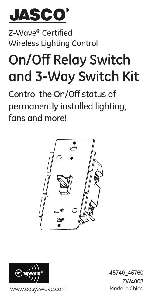
Z-Wave ® CertifiedWireless Lighting ControlOn/Off Relay Switch and 3-Way Switch KitControl the On/Off status of permanently installed lighting, fans and more!45740_45760ZW4003Made in ChinaIntroductionThank you for your purchase of a JASCO Z-Wave® control device. Z-Wave technology is designed to automate lighting/home control and provide easy remote operation of all your Z-Wave enabled devices. The JASCO Z-Wave product family includes a variety of devices to control lighting in your home. It is up to you whether you want to control one room or your entire house and whether you want to do it all now or start with one room and add more over time.This switch is one component of a Z-Wave® control system and is designed to work with all other Z-Wave enabled devices in a home control network. It will also act as a wireless repeater to insure that commands intended for another device in the network are received, thereby extending the range of the wireless controller. Z-Wave devices of other types and brands can be added to the system and will also act as range extenders if they support this function of repeating the signal received to other nodes in thesystem.This switch is designed for use only with permanently installed fixtures. The device controlled by this Z-Wave switch must not exceed 960 watts (Incandescent); 15 Amps, 1800W (Resistive); or ½ HP (Motor).NOT FOR USE WITH MEDICAL OR LIFE SUPPORT EQUIPMENT Z-Wave enabled devices should never be used to supply power to or control the On/Off status of medical and/or life support equipment!There are no user serviceable parts in this unit.Z-Wave ® CertifiedWireless Lighting ControlOn/Off Relay Switch and 3-Way Switch KitWIRELESS RANGEThis device complies with the Z-Wave standard of open-air, line of sight transmission distances of 65 feet. Actual performance in a home depends on the number of walls between the remote controller and the destination device, the type of construction and the number of Z-Wave enabled devices installed in the control network. Most Z-Wave devices act as signal repeaters and multiple devices result in more possible transmission routeswhich helps eliminate “RF dead-spots”.Things to consider regarding RF range:• Each wall or obstacle (i.e.: refrigerator, big screen TV, etc.)between the remote or Z-Wave device and the destination device will reduce the maximum range by approximately 25-30%. • Brick, tile or concrete walls block more of the RF signal thanwalls made of wooden studs and plasterboard (drywall). • Wall mounted Z-Wave devices installed in metal junctionboxes may suffer a significant loss of range (approximately 20%) since the metal box blocks a large part of the RF signal.Effects of Home Construction on Wireless Range Between Z-Wave Enabled DevicesNote: The distances shown in the table below are typical examples. Actual performance in your home will vary.* For Plug-in Modules or In-Wall Devices Installed in Plastic Junc-tion Boxes** Line of Sight / no obstructionsPlease Note: Z-Wave home control networks are designed to work properly alongside 802.11 wireless computer networks, Bluetooth and other 2.4GHz or 5.8GHz devices. Some baby cams, wireless video devices and older cordless phones using the 900MHz frequency range may cause interference and limit Z-Wave functionality. Many 900MHz products have a switch to select channel “A” or “B”. You may find that one of these channels will cause less interference than the other.IMPORTANT NOTE ABOUT 3-WAY CIRCUITSThe term “3-way circuit” refers to a circuit with two switches and one load (light) like you find at the top and bottom of a stairway. There are many ways to physically wire a 3-way circuit and it is important to understand how the circuit you wish to upgrade to Z-Wave control is wired. Below is a description of a typical 3-way circuit.From the Remote (or repeating Z-Wave module) to destination device:Type ofConstructionWood Frame with DrywallBrick, Tile or ConcretePlastic J-Boxes*Metal J-Boxes Plastic J-Boxes*Metal J-Boxes Number of Walls or Obstacles0**100’80’100’80’170’56’60’48’249’39’36’29’334’27’21’17’One of the ways to wire a two-switch/one-load circuit is to route the incoming power through the first switch, then to the second switch and then to the load. Although very common and by no means a standard, it is the easiest to convert to Z-Wave control. With this type of circuit, Switch 1 is replaced by the Z-Wave auxiliary switch and Switch 2 is replaced with the primary Z-Wave switch. The auxiliary switch does not actually control the power; instead, it sends a momentary voltage signal through the traveler wire to the primary switch which in turn, controls the power to the load.Typical 3-way circuit:Please consult an electrician if you have trouble identifying the type of wiring circuit you wish to convert or if you do not feel confident in your ability to convert the circuit to Z-Wave control.INSTALLATIONThis switch may be used in new installations or to replace an existing wall switch. It may be used by itself for 2-way control (one switch & one load), with one Auxiliary Switch for 3-way control (two switches & one load) or with two Auxiliary switches for 4-way control (three switches & one load). When used by itself for 2-way control, please make sure that the screw terminal for the traveler wire is insulated (Do Not Remove the tape over theterminal if you are not using the traveler connection).4-Way Wiring Schematic using one primary and two auxiliariesBlack – Load (to light fixture)Green - Ground Black – Line / Hot (from breaker)Single, Dual and Triple Gang BoxesWhen installing the 45740/45760 inmultiple gang boxes it may be necessary to break off one or both of the scored tabs on the front yoke. This does not affect the electrical rating of the 45740/45760.1. Shut off power to the circuit at fuse box or circuit breaker.2. Remove wall plate.! Warning: Verify power is OFF to switch box beforecontinuing. 3. Remove the switch mounting screws.4. Carefully remove the switch from the switch box. DO NOTdisconnect the wires.5. There are five screw terminals on the primary switch;these are marked LINE (Hot), Neutral, LOAD, GROUND and TRAVELER. The Traveler terminal is only used for 3-way or 4-way wiring and should remain insulated if the primary is being installed in a 2-way system (one switch & one load). Match these screw terminals to the wires connected to the existing switch. (Do Not remove the tape over the terminal if you are not using the traveler connection). 6. Disconnect the wires from the existing switch.7. Connect the green or bare copper ground wire to theGROUND terminal.8. Connect the black wire that goes to the light to the terminalmarked LOAD.9. Connect the black wire that comes from the electricalservice panel (Hot) to the terminal marked LINE.10. Connect the white wire to the neutral terminal.Note: UL specifies that the tightening torque for the screws is 14 Kgf-cm (12 lbf-in).TabsTabs Break at this line11. OPTIONAL for 3 or 4-way control): Connect the Travelerwire (usually Red) to the screw terminal marked TRAVELER.The other end of this Traveler wire connects to theTRAVELER screw terminal on the Auxiliary Switch. See the following section for information about wiring theAuxiliary Switch.12. Insert Z-Wave Switch into the switch box being careful notto pinch or crush wires.13. Secure the switch to the box using the supplied screws.14. Mount the wall plate.15. Reapply power to the circuit at fuse box or circuit breakerand test the system.Optional for 3 or 4-Way Control:1. The auxiliary switch requires the following 3 wiringconnections:a. The Traveler wire. This is used to send voltage signals to theprimary Z-Wave switch. The signals tell the Z-wave switch what action to perform.b. Ground.c. Neutral.2. DO NOT connect the auxiliary switch to the home’s blackHot (Line) wire.Observe Important Wiring InformationImportant: This switch is rated for and intended to only be used with copper wire.The home’s electrical wires may be attached to the screw termi-nals or inserted into the holes in the back of the switch enclosure and clamped in place by tightening the screw terminals. Always follow the recommended wire strip lengths when making wiring connections.Wire gauge requirements• Use 14 AWG or larger wires suitable for at least 80°C for supply (HOT), Load, Neutral and Traveler connections.• Use 14 AWG or larger wires suitable for 80°C for ground connection.Wire strip length:• For attachment to screw terminals: Strip insulation 1”(25mm).• For attachment using the enclosure’s holes: Strip insulation 5/8” (16mm).You should now be able to use the rocker to manually turn On/Off the connected load.Use your primary controller to include the switch in the home control network after the switch is wired as shown in the above diagram. It can then be added to groups and/or lighting scenes and managed remotely to control the On/Off status of the connected lighting.Key Features• Remote On/Off control via the Z-Wave controller/network • Manual On/Off control with the front panel rockerBASIC OPERATIONRemote ControlJASCO Z-Wave remotes provide control of an Individual device, Groups of devices and Scenes. Other brands of Z-Wave Certified remotes may not offer as much flexibility in how you can set up your lighting control network. Please refer to your remote control’s instructions for details on its capabilities and instructions for add-ing and controlling devices.Manual ControlThe primary switch allows the user to:Turn ON/OFF the connected lighting.• To turn the connected lighting ON: Tap the top of the rocker.• To turn the connected lighting OFF: Tap the bottom of the rocker.Program your Light Switch (Include or exclude the switchto/from the Z-Wave home control network.)• Refer to the instructions for your primary controller to access the network setup function and include or exclude devices.• When prompted by your primary controller, tap the top or bottom of the rocker.• The primary controller should indicate that the action was successful. If the controller indicates the action wasunsuccessful, please repeat the procedure.• Once the switch is part of the network, the same basic procedure is used to add the switch to groups & scenesor change advanced functions. Refer to the primarycontroller’s instructions for details.Please Note: After a power failure, the Z-Wave primary switch returns to the last used state.ADVANCED OPERATIONThe following Advanced Operation parameters require that you have an advanced controller like the JASCO model 45601 LCD remote. Advanced remotes from other manufacturers may also be able to change these settings; however, basic remotes do not have this capability.All On/All OffDepending upon your primary controller, the primary switch can be set to respond to ALL ON and ALL OFF commands in up to four different ways. Some controllers may not be able to change the response from its default setting. Please refer to your controller’s instructions for information on whether or not it supports the configuration function and if so, how to change this setting.The four possible responses are:It will respond to ALL ON and the ALL OFF command (default).It will not respond to ALL ON or ALL OFF commands.It will respond to the ALL OFF command but will not respond to the ALL ON command.It will respond to the ALL ON command but will not respond to the ALL OFF command.Invert SwitchIf the switch is accidentally installed upside down with “On” at the bottom and “Off” at the top, the default On/Off toggle settings can be reversed by changing parameter 4’s value to “1”.• Parameter No: 4• Length: 1 Byte• Valid Values = 0 or 1 (default 0)Restoring Factory DefaultsAll Configuration Parameters can all be restored to their factory default settings by using your primary controller to delete/reset the device.Interoperability with Z-Wave™ DevicesA Z-Wave™ network can integrate devices of various classes, and these devices can be made by different manufacturers. Al-though every Z-Wave certified product is designed to work with all other Z-Wave certified products, your controller must include the appropriate device classifications in order to control non-lightingZ-wave devices. As an example, the JASCO 45600 basic remoteis designed only for controlling Z-Wave devices using the lighting control classification. The JASCO 45601 deluxe remote with LCD readout can control other Z-Wave certified devices like thermo-stats as well as lighting.WARRANTYJASCO Products warrants this product to be free from manufac-turing defects for a period of two years from the original date of consumer purchase. This warranty is limited to the repair or replace-ment of this product only and does not extend to consequential or incidental damage to other products that may be used with this product. This warranty is in lieu of all other warranties, expressedor implied. Some states do not allow limitations on how long an implied warranty lasts or permit the exclusion or limitation of inci-dental or consequential damage, so the above limitations may not apply to you. This warranty gives you specific rights, and you may also have other rights which vary from state to state. Please contact Customer Service at 800-654-8483 (option 4) between 7:30AM – 5:00PM CST or via our website () if the unit should prove defective within the warranty period:JASCO Products CompanyBuilding B, 10 E Memorial Rd.Oklahoma City, OK 73114FCCU2ZZW4003The Federal Communication Commission Radio Frequency Inter-ference Statement includes the following paragraph:The equipment has been tested and found to comply with the limits for a Class B Digital Device, pursuant to part 15 of the FCC Rules. These limits are designed to provide reasonable protection against harmful interference in a residential installation.This equipment uses, generates and can radiate radio frequency energy and, if not installed and used in accordance with the instruction, may cause harmful interference to radio communica-tion. However, there is no guarantee that interference will not occur in a particular installation. If this equipment does cause harmful interference to radio or television reception, which can be determined by turning the equipment off and on, the user is encouraged to try to correct the interference by one or more of the following measures:• Reorient or relocate the receiving antenna• Increase the separation between the equipment and receiver• Connect the equipment into an outlet on a circuit different from that to which the receiver is connected• Consult the dealer or an experienced radio/TV technician for helpOperation is subject to the following two conditions:• This device may not cause interference• This device must accept any interference, including interference that may cause undesired operation ofthe device.Important Note: To comply with the FCC RF exposure compliance requirements, no change to the antenna or the device is permit-ted. Any change to the antenna or the device could result in the device exceeding the RF exposure requirements and void user’s authority to operate the device.Compliance with IC Rules and RegulationsIC: 6924A-ZW4003Jasco Products CompanyModel: 45740 ZW4003ICES-3(B) / NMB-3(B)This device complies with Industry Canada license-exempt RSS standard(s). Operation is subject to the following two conditions: (1) this device may not cause interference, and (2) this device must accept any interference, including interference that may cause undesired operation of the device.SPECIFICATIONSZW4003Power: 120 VAC, 60 Hz.Signal (Frequency): 908.42 MHz.Maximum Loads: 960W, incandescent, ½ HP Motor or 1800W (15A) ResistiveRange: Up to 100 feet line of sight between the Wireless Controller and the closest Z-Wave receiver module.Operating Temperature Range: 32-104° F (0-40° C)For indoor use only.Specifications subject to change without notice due to continuingproduct improvementZ-Wave is a registered US trademark of Sigma DesignsJasco Products Company LLC,10 E. Memorial Road,Oklahoma City, OK 73114.© 2013 JascoProducts45740_45760ZW4003rev. 09/06/13。
ZW说明书(2014.4首版)
注意:不正确吊装可能对电动装置造成损坏,对于不正确安装、吊装所造 成的设备损坏,本公司不予承担!!!
常州兰陵自动化设备有限公司
Changzhou Lanling Automation Equipment Co., Ltd.
概述
多回转阀门电动装置,主要用于启闭件做直线运动的阀门配套使用,如闸阀、截止阀、隔膜阀、闸门等,用于对阀门 的开启、关闭、调节。是阀门实现远控、集控和自控必不可少的驱动装置。具有功能全、性能可靠、控制系统先进、体积 小、重量轻、使用维护方便等特点。
电动装置与阀门组装后,必须对行程、开度指示器分别进行调整,方可使用;调整前,必须检查开度指示器上的电位 器是否已脱开(把电位器轴上齿轮的紧定螺钉松开即可),以防损坏;检查电机的旋向,控制线路是否正确,以防电机失控。
普通户外型电动装置调试方法
一、力矩控制器的调整(参见图5) 出厂时已按用户的要求调整好转矩,一般不需再调整。如需改变整定值,可旋转凸轮的调整轴至相应刻度,先调关
开度指示器与开度电位器外形结构
为全系列通用部件,其结构见图6。输入齿轮由计数器个位齿轮带动,经减速后,指示盘随开阀、关阀的过程转动、 指示阀门的开启或关闭位置。电位器轴和指示盘同步转动,供远传开度指示用,移动转圈数调整齿轮可以改变指示盘开 到位与关到位之间的角度;开度电位器的调整:开度电位器旋转角度为270°旋转角,将计数器齿轮调整到相应的变比 档位,在调整好电动装置行程限位开到位、关到位,依据带电位器齿轮的旋转方向,调整好电位器的旋转角度(应该小于 270°大于180°),电位器在起始位应当留有一定的余量。
普通型电动装置原理图及端子出线图
普通型电动装置电气控制原理图见(图8)端子出线图见(图9)
注:特殊线路可根据用户要求设计定做
- 1、下载文档前请自行甄别文档内容的完整性,平台不提供额外的编辑、内容补充、找答案等附加服务。
- 2、"仅部分预览"的文档,不可在线预览部分如存在完整性等问题,可反馈申请退款(可完整预览的文档不适用该条件!)。
- 3、如文档侵犯您的权益,请联系客服反馈,我们会尽快为您处理(人工客服工作时间:9:00-18:30)。
ZW43-12型
户外高压真空断路器
使
用
说
明
书
浙江X X电气有限公司
1主要用途
ZW43-12型户外高压真空断路器(以下简称断路器)是额定电压为12KV,50HZ三相交流的户外配电设备。
主要用于配电网开断,关合电力系统中的负荷电流,过载电流及短路电流。
适用于变电站及工矿企业配电系统中做保护和控制,适用于农村电网及频繁操作的场所,特别适用于城亡,农网改造的需要。
本安装使用说明书规定了断路器的主要技术参数,产品结构,以及操作,安装使用维护的原理和方法等内容。
1.2 引用标准
GB19841989《交流高压断路器》
GB/T110221999《高压开关设备和控制设备标准的共用技术要求》
GB311.11997《高压输变电设备的绝缘配合:高压试验技术》
GB33091989《高压开关设备在常温下的机械试验》
DL/T4032000《12~40.5KV高压真空断路器订货技术条件》
1.3 使用的环境条件
1.3.1海拔高度不超过2000m;
1.3.2周围空气温度不超过:-45℃~+40℃;
1.3.3风速不大于35m/s;
1.3.4污秽等级:Ⅳ
1.3.5安装场所:无易燃,爆炸危险,化学腐蚀的场所;
1.3.6地震强度不超过8度
1.4 主要特点
1.4.1 断路器采用三相支柱式结构,具有开断性能稳定可靠,无燃烧和爆炸危险,免维护,体积
小,重量轻和使用寿命长等特点。
1.4.2断路器采用全封闭结构,密封性能好,有助于提高防潮,防凝露性能特别适应于严寒或潮
湿地区使用。
1.4.3三相支柱及电流互感器采用进口户外环氧树脂固体绝缘,具有耐高低温,耐紫外线,耐老
化的特点。
1.4.4操作机构采用小型化弹簧操作机构,分合闸能耗低;机构传动采用直动传输方式,分合闸
部件少,可靠性高。
操作机构置于密封的机构箱中,解决了机构锈蚀的问题,提高了机构的可靠性。
1.4.5断路器的分,合闸操作可采用手动或电动操作及远方操作。
可与控制器配套实现配电自动
化,也可以与重合器配合组成重合器/
1.4.6断路器可以装设二相或三相CT,供过电流自动脱扣保护和智能控制器进行信息分析。
1.4.7断路器重量<100kg
1.5 产品型号
ZW 43-12/630-□(G)
隔离开关
额定短路开断电流(KA)
额定电流(A)
最高工作电压(KV)
设计序号
户外真空断路器
2.
2.1主要技术参数见表1。
2.2机构特性见表2。
2.3操作机构特性见表3。
3.1手动机构动作原理
3.1.1 合闸操作:
先拉动储能手柄进行储能,所施力矩由小变大,当弹簧过中瞬间时,合闸弹簧释放能量,促使储能系统逆时针旋转并带动传动拐臂转动,带动传动轴使开关合闸,同时分闸拐臂扣住分闸半轴,使断路器处于合闸状态,凸轮与传动轴套脱离,机构不能再次合闸。
3.1.2 分闸操作:
断路器合闸后,拉动分闸手柄,使分闸半轴转动,分闸拐臂解扣,传动杆在分闸弹簧的带动下使开关分闸。
3.1.3 如果使用消涌流装置,当线路电流超过设定值时,过流线圈被驱动,撞击分闸半轴分闸拐臂解扣,传动轴在分闸弹簧的带动下使开关分闸。
3.1.4 手动机构(带消涌器)的电路原理及内部接线图如图3所示
3.2 储能:
拉动储能手柄,或电动机转动,在传动齿轮的带动下使凸轮转动,合闸弹簧被逐渐拉长,当弹簧过中后,凸轮由定位件保持不再转动,开关处于准备合闸状态;
同时凸轮与传动轴脱离,使机构不能再次储能。
3.2.2 合闸操作:储能完毕后,拉动手动合闸手柄或给合闸线圈旋压,使合闸半轴转动,合闸拐臂与合闸半轴解扣,合闸弹簧释放能量,带动传动轴使开关合闸,同时分闸弹簧被储能。
机构在合闸状态下,再进行储能操作,合闸弹簧再次被拉长,弹簧过中后,合闸半轴被连锁装置扣住,避免机构误合闸。
再合闸已储能状态,机构处于重合状态,可实现“分-0.3-合分”一次重合闸操作。
3.2.3 分闸及过流脱扣过程:断路器合闸后,拉动分闸手柄或给分闸线圈施压或当线路电流超过消涌流装置的设定时,过流线圈被驱动,都使分闸半轴转动,分闸拐臂与分闸半
轴解扣,分闸弹簧释放能量,带动传动杆使开关分闸。
3.2.4 电动装置典型电路原理及内部接线图见图4
4.
4.1 对于需要加装隔离开关的用户,可选用ZW43-12G系列开关,外形尺寸及结构图见图2。
隔离开关用螺栓固定于ZW43-12断路器的机构箱上,坚固,稳定,拆卸方便,可靠,可灵活加装。
4.2隔离开关主要技术参数见表3
4.3 隔离开关结构特点
隔离开关由隔离架,绝缘子,绝缘拉杆,刀片,隔离主轴,进线板,操作手柄,电流互感器等组成。
隔离支架固定在机构箱上,利用断路器的接线端作为闸刀的支点,构成隔离断口的一端,断口的另一端通过操作绝缘子和驱动轴打开、关合刀闸。
三相联动,在隔离开关分闸状态下有明显的可见断口,并具备与断路器本体之间的可靠防误机构联锁,维护方便,安全。
4.4 隔离开关操作顺序
4.4.1合闸操作(送电操作)
a) 拉动隔离开关操作手柄,闭合隔离刀,闭合到位;
b)拉动断路器储能手柄(储能);
c)拉下断路器合闸拉环,断路器合闸。
4.4.2 分闸操作(断电,检修操作)
a)拉下断路器分闸拉环,断路器分闸;
b)拉动隔离开关操作手柄,打开隔离刀,打开到位。
4.4.3 注意事项:a)严禁在断路器合闸时,分合隔离开关;b)隔离开关必须分合到位,否则断路器不得进行分合闸操作。
5.
5.1产品在运输过程中不得翻转、倒置,并要采取防震措施。
起吊断路器时,必须勾住箱体上的四个耳环吊起。
不得直接搬运环氧绝缘套筒。
5.2 开箱后应检查断路器户外环氧绝缘套筒有无破裂,箱体是否变形,分合批示是否齐全,产品铭牌、合格证是否与订货单相符,装箱清单是否与实物相符。
5.3 断路器投入运行前,应仔细核对各操作元件的额定电压、额定电流与实际情况是否相符。
5.4断路器的触头参数和机械特性参数在出厂检验时就已经调整好,用户不必开箱检查。
按要求进行耐压试验后,既可安装。
有条件可以按照表2的要求进行机械特性检查。
5.5断路器可以单杆架设,也可以双杆架设。
断路器应平衡、牢固地安装在专用钢架上使用(如图5所示)
6
6.1 本断路器因其特殊的设计结构确保使用中长期免维护,只需每隔三年左右进行一次工频耐压试验。
6.2用户不得随意更换使用与原型号规格不一致的电器元件。
6.3操作人员应初步了解机构的性能及安装调整、维护知识,对运行中问题应予以记录,必要时可通知制造厂家。
7
7.1 产品合格证一份。
7.2 出厂检验报告一份。
7.3 安装使用说明书一份。
8 订货时要说明产品的型号、名称、数量、额定电流、额定开断电流、所配电互感器电
流比、操作方式及操作电压,电动的要说明分合闸需要交流还是直流,远程控制后备电源的电压等。