台车使用说明书
衬砌台车安全操作规程范本
衬砌台车安全操作规程范本衬砌台车是一种常见的工业设备,用于搬运和运输重物。
为了确保操作人员和周围工作环境的安全,使用衬砌台车时应遵守以下操作规程:1. 在操作前,应确保衬砌台车所处的工作区域清洁、整齐,并确保没有障碍物。
同时,操作人员应穿戴符合安全要求的工作服,并佩戴安全帽、安全鞋等必要的个人防护装备。
2. 在使用衬砌台车之前,应先对设备进行全面检查,确保其各项功能正常运行。
特别要检查制动系统、操纵装置和提升系统,并确认设备的稳定性和结构完整性。
3. 在操作前,要确保衬砌台车上的负载稳固,并与横梁或其他支撑平稳连接。
同时,根据负载的大小和形状,合理调整杠杆的位置和高度,以确保负载的平衡和安全运输。
4. 在操作过程中,要注意保持衬砌台车的稳定。
不得急转急停或突然改变行驶方向,以免引起负载的晃动和不稳定。
在行驶过程中,应以适当的速度和力量推动衬砌台车,保持平稳的运行。
5. 在提升重物时,操作人员要控制好衬砌台车的提升速度,避免因过快的提升速度导致负载滑落或衬砌台车倾覆的危险。
同时,在提升过程中,要注意观察负载状态,确保负载没有超过设备的承载能力。
6. 在使用衬砌台车时,要确保周围工作区域的安全。
要避免与其他人员或设备发生碰撞,不得超速行驶,保持足够的安全距离。
同时,要注意观察周围环境的变化,及时采取措施应对可能的危险情况。
7. 在操作结束后,应将衬砌台车归位并停放在指定位置。
将设备上的控制杆、按钮等归零,并切断电源。
同时,要清理和整理工作区域,确保没有遗留物和杂物。
8. 定期对衬砌台车进行检修和维护,保证其功能和性能的持续可靠。
及时更换磨损的零部件,修复设备的故障和缺陷,并定期进行润滑和清洁。
9. 在任何紧急情况下,如设备故障、事故等,操作人员应立即停止操作,并及时报告有关部门或负责人。
同时,要采取必要的紧急避险措施,避免进一步的危险和损失。
10. 操作人员应接受相关的安全培训和指导,熟悉衬砌台车的操作规程和安全注意事项。
台车使用说明书
中铁五局路桥公司盐沙线小关2#隧道液压衬砌台车使用说明书屮铁八局集团第三工程有限公司物资设备租赁站目录一、.................................. 设计依据2二、...................................... 用途2三、............................ 技术及结构特征2四、.................................. 使用说明2五、.............................. 安全操作说明4六、附件(资料) (6)1.液压系统图2.电气原理图3.台车总装图4.配件表液压衬砌台车使用说明书一、设计依据中铁五局路桥公司贵阳盐沙线项目部提供图纸设计。
二、用途该台车适用于贵阳市政工程盐沙线小关2#隧道。
三、技术及结构特征四、使用说明一)、操作前准备:1、仰拱万仝浇注完毕,上铺枕木,枕木截面尺寸为200X160(厚)mm, 长度为400—600mm,铺设间隔500mm左右,且枕木需用铁丝捆绑。
2、台车走行轨道中心线应和隧道中心线重合,铺设误差不得大于20mm。
钢轨10m范围内直线误差不得超过15mm.轨距为10m, 两轨高差应控制在±15mm内。
二)、行走操作:1、检查各模板是否完全脱离了衬砌表面,离开的距离应大于50mm, 并检查作业窗是否能合拢,螺栓是否松动,在作业过程中每3—5 个作业循环紧固一次螺栓。
2、检查模板底部是否被地面的障碍物顶住或挡住,如有杂物应移开。
3、检查地梁支撐螺杆是否已经收起并离开钢轨面lOOmmo4、检查台车上是否有未妥善安置的物品,如有应放置在安全不易抖落的地方。
5、台车行走时,可根据施工要求利用模板台车作为操作平台。
三)、定位操作:1、全面检查电气、液压、行走系统是否正常。
2、台车灌注前应打磨台车表面的碗及朵物后,刷脱模剂。
3、对位时应由测量人员来确定台车的位置,搭接长度最好控制在100mm以内,确定后应在轮子双向加阻车器(铁楔子或木楔子),防止因坡道或灌注捣固使其产生位移。
Simba 1354采矿凿岩台车说明书
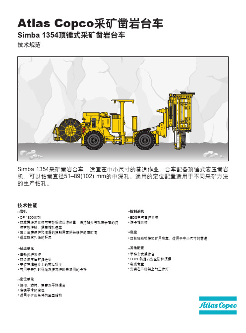
Simba 1354采矿凿岩台车,适宜在中小尺寸的巷道作业。
台车配备顶锤式液压凿岩机,可以钻凿直径51–89(102) mm 的中深孔。
通用的定位配置适用于不同采矿方法的生产钻孔。
技术性能››岩机OP 1800系列双减震缓冲系统可有效吸收反冲能量,保持钻头与孔底岩石的持续有效接触,提高钻孔速率压力油膜保护和润滑的接触界面延长维护间隔时间适应既定孔径的钎尾››钻进单元自动换杆系统双级液压油缸推进梁安装在推进梁上的前后顶尖可用于开孔时导向及接卸杆时夹紧用的卡钎››定位单元俯仰、旋转、摆臂及平移滑台准确平滑的定位适用于矿山条件的坚固结构•••••••••••››控制系统EDS 电气直控系统防卡钻系统››底盘四轮驱动铰接式矿用底盘,适用于中小尺寸的巷道››其他配置手推车式操作台FOPS 防落石安全防护顶棚电缆卷盘安装在三脚架上的工作灯•••••••Atlas Copco 采矿凿岩台车Simba 1354顶锤式采矿凿岩台车技术规范RHS 17自动换杆器,自动接杆 ………………………………17+1根宜用1.2m 、1.5m 或1.8米长度的钻杆宜用R32、T38或T45的快速钻杆宜用TDS56或TDS64导向钻管自动接杆钻深可达32m推进延伸补偿行程 (1.2m 钻杆) ……………………………900mm 推进延伸补偿行程 (1.5m 或1.8m 钻杆) ………………………1200mm BHR 60–2回转装置:回转角度360°BHT 15型滑台,最大平行孔间距:1.5mBHP 15型摆臂,可实现1.5m 帮壁的平行孔定位,和增加上向和下向孔1.5m 的平行定位进而达到3m 的平行定位(摆臂+滑台)推进梁后顶尖 ……………………………………………BSJ 8-200推进梁前顶尖 ……………………………………………BSJ 8-115推进梁倾斜角度 ……………………………………前倾20˚ 后仰65˚EDS 电气直控系统基本功能包括半自动钻孔及防卡钻功能液压泵:用于冲击液压泵:用于回转、定位、推进油泵卸载启动系统最大压力 …………………………………………………230bar 液压油箱最大容量 ……………………………………………160 L 低油位报警及自动停机油箱上装有油温表电动加油泵回油过滤 ………………………………………………………16μm 液压油过滤器阻塞报警器液压油不锈钢水冷却器矿物基液压油•••••••••••••••••••••••••••技术规格总装机功率 ……………………………………………………70kW 主电机功率 ……………………………………………………55kW 电压 ………………………………………………………380-1000 V 频率 …………………………………………………………50-60 Hz 启动方式 …………星型/三角形 (380 - 690 V), 1000 V 直接启动电机热过载保护主电箱面板上配有冲击计时表主电箱内配有数字式电压/电流表相序指示器漏电指示器电瓶充电器变压器容量 ………………………………………………………4kVA 电缆卷盘电缆卷盘限位开关装在三角架上的工作照明灯 …………………………2x200 W, 24 V凿岩机润滑供气空压机 ………………………………………………Atlas Copco LE7在转速5400 rpm 压力7bar 时的排风量 ………………………12 L/s 风压表风压/风量可调外接气的吹孔装置电动增压水泵在10bar 增压压力下最大流量 ……………………………… 100L/min 最小进口水压 ……………………………………………………2 bar 水压表水流表Deutz D914 L04,四缸四冲程预燃式柴油发动机,满足EP A III/COM III(Tier 3/Stage • IIIA) 标准功率 (转速为2300 rpm 时) ……………………………………55kW 扭矩 (转速为1550 rpm 时) ……………………………………230Nm 固定式座椅,配有安全带铰接转向 …………………………………………………±41˚ 转角四轮驱动FOPS 防落石认证顶棚液压助力转向系统液力变矩器 ………………………………………………Clark 12000前桥 ………………………………………………………DANA 176 后桥 ………………………………………DANA 176,±8˚摆动角前桥防滑自锁差速器轮胎 ………………………………………………………12.00xR20接近角和离去角 …………………………………………………15˚ 可展开式液压前支腿 ……………………………………………2个液压后支腿 ………………………………………………………2个行车制动:两条独立的回路 (液压实施,全封闭湿式多盘制动器)紧急和泊车制动 ……………………SAHR (弹簧制动,液压释放)燃油箱容积 ………………………………………………………60 L 电气系统电压 …………………………………………………… 24V 蓄电池 ………………………………………………………2 x 70Ah 行走照明灯 …………………………………………………8 x 70W 刹车灯通往操作平台的照明阶梯集中润滑系统灭火器水平仪最大爬坡能力 ……………………………………………………1∶4行走速度 (平地/1∶8坡道) …………………………………>10/>4km/h 喇叭,警示灯及倒车报警器•••••••••••••••••••••••••••••••••••••••••••••••••••••••• Simba1354Simba1354可选件设备尺寸侧视图25545º7507502380243019501500200045º945115070018452260318023011500155523048763 with BMH 216 (B)20º65º1500380o3000 (PH)1500(P H )750750489052207440R2970(RD )R 2790 (PH )覆盖范围前视图RD —环形炮孔组钻进PH—平行炮孔组钻进本文图片所示设备可能配有选装部件。
Eurotec 振动台车使用手册说明书

From February 1st, 2017 SAMES Technologies SAS becomes SAMES KREMLIN SASUser manualEurotecCart with vibrating tableSAMES Technologies. 13 Chemin de Malacher 38243 Meylan CedexTel. 33 (0)4 76 41 60 60 - Fax. 33 (0)4 76 41 60 90 - Index revision : A17087_EUAll communication or reproduction of this document, in any form whatsoever and all use or communication of its contents are forbidden without express written authorisation from SAMES Technologies.The descriptions and characteristics mentioned in this document are subject to change without prior notice.© SAMES Technologies 2010WARNING : SAS Sames Technologies is registered with the Ministry of Labour as a training institution.Throughout the year, our company offers training courses in the operation andmaintenance of your equipment.A catalogue is available on request. Choose from a wide range of courses toacquire the skills or knowledge that is required to match your productionrequirements and objectives.Our training courses can be delivered at your site or in the training centre at ourMeylan head office.Training department:Tel. 33 (0)4 76 41 60 04E-mail:**************************SAS Sames Technologies operating manuals are written in French and translated into English, German, Spanish, Italian and Portuguese.The French version is deemed the official text and Sames will not be liable for the translations into other languages.Index revision : A27087_EUEurotecCart with vibrating table1. Health and safety instructions- - - - - - - - - - - - - - - - - - - - - - - - - - - - - 42. Description- - - - - - - - - - - - - - - - - - - - - - - - - - - - - - - - - - - - - - - - - - 52.1. General presentation . . . . . . . . . . . . . . . . . . . . . . . . . . . . . . . . . 52.1.1. Vibrating table . . . . . . . . . . . . . . . . . . . . . . . . . . . . . . . . . . . . . . . 52.1.2. Support arm for powder pump. . . . . . . . . . . . . . . . . . . . . . . . . . . 52.1.3. Control panel . . . . . . . . . . . . . . . . . . . . . . . . . . . . . . . . . . . . . . . . 53. Characteristics - - - - - - - - - - - - - - - - - - - - - - - - - - - - - - - - - - - - - - - 63.1. General characteristics . . . . . . . . . . . . . . . . . . . . . . . . . . . . . . . 63.2. Pneumatic characteristics . . . . . . . . . . . . . . . . . . . . . . . . . . . . . 64. Operation- - - - - - - - - - - - - - - - - - - - - - - - - - - - - - - - - - - - - - - - - - - 65. Tools - - - - - - - - - - - - - - - - - - - - - - - - - - - - - - - - - - - - - - - - - - - - - - 66. Installation - - - - - - - - - - - - - - - - - - - - - - - - - - - - - - - - - - - - - - - - - - 76.1. Set up procedure . . . . . . . . . . . . . . . . . . . . . . . . . . . . . . . . . . . . 87. Troubleshootings - - - - - - - - - - - - - - - - - - - - - - - - - - - - - - - - - - - - - 88. Spare parts- - - - - - - - - - - - - - - - - - - - - - - - - - - - - - - - - - - - - - - - - - 9 Index revision : 31. Health and safety instructionsWARNING : This manual contains links to the following user manual•see RT Nr 7079_EU for MG 400-AG 400 spray guns and CGU 400 control module.Note: This device complies with the ATEX directive. It may be dangerous if it is not used in com-pliance with the safety regulations specified in this manual.WARNING : This cart is intended for use with powder-paint spraying apparatus only (MG 400 manual spray gun and AG 400 automatic spray gun).•This device must only be used by personnel trained and accredited by SAMES Technologies.Operating staff must first read the user manual and the user manuals for any peripheral electrical equipment present in the spraying area. The workshop manager must ensure this is the case.•The cart must always be installed and used in areas where there is no risk of explosion.•It is essential to connect the bonding strip under the vibrating table and to connect the CGU 400 control module to the ground to guarantee the safety of operators and correct operation of the powder-coating equipment.•When a vibrating table is used, the plastic bag containing the powder must be tightly wrapped around the plunger tube to avoid any escape of powder, which could create an explosive atmos-phere.•The box must be filled in a ventilated area designed for the purpose and under no circumstances anywhere near the cart.•Under no circumstances may the cart be used to carry or transport loads other than the powder tank or a powder box with a maximum weight of 30 kg on the vibrating table.•Ambient temperature must not exceed 40 °C (104°F).•The spraying area must be kept clean and clear of any unnecessary items.•The floor on which the operator works must be anti-static (bare concrete or metal duckboard).Never use an insulating floor covering.•Powder spraying must be carried out in front of a ventilated booth designed for the purpose. Start-up of the CGU 400 control module must be interlocked with operation of the ventilation system.•Skin-contact with or inhalation of products used with this equipment may be dangerous for personnel (cf.: Safety sheets for products used).•The parts to be painted must have a resistance with respect to ground that is less than or equal to 1MΩ.•Powder-spraying equipment must be maintained regularly according to the instructions laid out in this manual.•Only genuine Sames Technologies spare parts can guarantee operating safety for the equipment.•Genuine SAMES hoses must be used to connect the powder pump.Index revision : A47087_EU2. Description2.1. General presentationThe convenient, compact size of the cart makes it easy to manoeuvre and move, with fourfreely-steerable wheels. The MG 400 manual spray gun is fixed to the cart by a hook. The cart also includes the CGU 400 control module.2.1.1. Vibrating tableThis component enables standard powder boxes of up to 30 kg to be easily used.It is fitted on the cart at a slight angle, in order to ensure the powder is fully taken up, even from the bot-tom of the box.A high-performance pneumatic vibrator is used to vibrate the powder and minimise compaction. Vibra-tion frequency can be adjusted according to the type of powder used and level of product remaining. Vibrator operation is activated with the spray gun trigger.2.1.2. Support arm for powder pumpIntegrated into the cart, it supports one or two powder pumps. It ensures a correct positioning in the pow-der box.Gradually, the tube of the powder pump slides at the same time as the level of powder comes down in the box.In order to facilitate the replacement of the powder box, the arm is locked in a high position releasing sufficient space.2.1.3. Control panelItem Function1Vibrator air supply pressure adjustment and reading (for vibrating table)2Fluidisation air flow-rate adjustment (plungertube)Support arm forpowder pumpCart2Index revision : A57087_EUIndex revision : A 67087_EU3. Characteristics3.1. General characteristicsBecause of the structure of the cart:• a box with a weight of approximately 30 kg (66 lb) and with maxi. dimensions of 430 x 430 x 430of powder can be placed on a vibrating table.3.2. Pneumatic characteristicsCharacteristics of the compressed-air supply according to standard NF ISO 8573-1:* : Air flow-rate values are given for a temperature of 20° C (68 °F) at an atmospheric pressure of 1013 mbar.Powder maximum flow-rate: variable until 500g/min “Fluidisation” air: until 4 bar (58,8 psi) max.4. OperationThe powdered paint remains in its original box. The box is placed on the vibrating table.The vibrator vibrates the table and enables the fluidisation head to reach the bottom of the powder box.The fluidisation nozzle, with its compressed air supply, “fluidises” the powdered paint.The powdered paint, fluidised in this way, is then carried by an air jet from the powder pump to the spray gun to which it is connected by a powder-carrying hose.5. ToolsNo specific tools.Cart dimensions (h x w x d)1080 x 450 x 620 mm Approximate weight (without powder)40 kg.Operating temperaturefrom 0°C to 40°C (32°F to 104°F).Maximum dew point at 6 bar (87 psi)class 4, i.e. + 3 °C (37 ° F)Maximum particle size of solid contaminants Class 3, i.e. 5 µm. Maximum oil concentrationClass 1, i.e. 0.01 mg/m 03 *Maximum concentration of solid contaminants5 mg / m 03*Cart air supply pressure7 bar max (101.5 psi)6. InstallationWARNING : This equipment must be imperatively connected to the ground.•Carefully remove units and components from packaging, and check contents against packing list.•Install the cart in a secure manner and placed at least 1,5 m of any opening of the booth (see RT Nr 7079_EU ). Secure the CGU 400 control module on the cart using the two M6 x 10 screws and the two locking washers with a 5mm allen wrench.•Connect the airlines to the outlet ports of the rear panel of the Gun Control Unit as follows : (see RT Nr 7079_EU for the rear panel illustration and key to symbols).1Red airline from Venturi Jet to the 'Powder Delivery Air Supply Output'.2Blue airline from Venturi Dilution Port to the 'Powder Dilution Air Supply Output'.3Black airline from the Guns to the 'Gun Air Supply Output'.Equipment with vibrating table, connect the colorless airlines from the vibration control regula-tor and the Fluidising Pad (which are joined with a “T” connector) to the ‘Vibrating Box Air Supply Output’ at the top right hand corner of the control unit.NOTE: The powder pump is identified by a Red washer & the Dilution Port by a Blue washer.•Connect the black airline (Dia: 8mm) to the centre right hand air fitting on the rear of the gun control module (see RT Nr 7079_EU).•Insert the suction tube on the front bracket of the articulated arm until it latches into position.•Ensure that the three airlines which exit the front of the articulated arm are connected as follows: 1Red airline to ”Powder delivery” air fitting at the top rear of the powder pump (the sealing washer of this fitting is red).2Blue airline to ”Powder dilution” air fitting at the top centre of the powder pump (the sealing washer of this fitting is blue).3Black airline to the ”Fluidising pad” coupling fitting on the top of the powder pump mounting bracket.•Secure the gun hook to the side of the cart using the M 6x 50 socket cap head screw.•Connect the powder hose to the powder pump.•Connect an air supply hose to the ball valve mounted on the side of the cart.Index revision : A77087_EU6.1. Set up procedure•Step 1: Ensure that all switches are in the OFF position and that all pressure regulators are closed, (the knobs should be turned fully anti-clockwise). The knob of the pressure regulators are unlocked by pulling outwards and locked by pressing inwards.•Step 2: Lift the articulated arm to its maximum height and push down on the front of the powder pump support brack to lock the arm into a parked position.•Step 3: Place an open box of powder onto the vibrating table.•Step 4: Lift the front of the powder pump support bracket and lower the articulated arm and suction tube so that the fluidized suction head is lowered onto the powder. The tube enters the powder during the application and digs into the powder towards the front corner of the box.•Step 5: Turn on the ”Mains Electrical” (third on the right) switch of the control module to the positionmarked•Step 6: In the spraying booth, press the trigger of the spray gun. A red LED lights next to the ”T”symbol on the display.•Step 7: With the trigger still pressed, open the flow regulator to approximately 2 bars (29.4 psi) on the side of the cart. Then open the flow adjuster by turning the knob anti-clockwise until a slight disturbance of powder is noticed around the fluidizing pad at the bottom of the suction tube. This air supply should be kept to a minimum consistent with smooth powder flow to prevent powder from being ejected from the box into the surrounding air.The flow adjuster, equipped with a lock nut, may be used to lock the fluidisation setting.To set up the spraying: see RT Nr 7079_EU.7. Troubleshootingssee RT Nr 7079_EUIndex revision : A87087_EU8. Spare parts17Index revision : A97087_EUIndex revision : A 107087_EU(*)Level 1: Standard preventive maintenance Level 2: Corrective maintenance Level 3: Exceptional maintenanceItem Part Number Description QtySale Unit Spare Part Level (*)EU75009004Eurotec Cart with vibrating table 113 1EU5009010Pivot axle4132EU9001031Pneumatic vibrator1123EU9000105Male straight union 1/4 D61134EU9000065Rubber pivoting roller - Dia:753135EU9000064Conductive rubber pivoting roller Dia:751136EU9000355Damper1137EU9001064Bonding strip - 30A 113E4CSPR085Blue lug - Dia: 61138EU9001892Mini Ball valve 1/41139EU9000170Colorless polyurethane 4x6 hose 2,5m 310U1GLBT152Blue polyurethane 4x6 hose 1,25 m 311U1GRBW198Red polyurethane 4x6 hose 1,25 m 312EU9000171Black polyurethane 5.5x8 hose0,75m 313F6RLCS508Cylindrical male union bracket M5 D6 11314EU9000203Black polyurethane 2.5x4 hose 0,25m 315EU75009007Regulator 4 bar 11316F6RLTS485Equal T ee Dia: 611317EU9000363Flow adjuster11318EU9000052Female straight union 1/8 D411319EU9001879Pressure gauge (4 bar)113。
凿岩台车说明书

作业台
升降高度 (m)
数量
约9(地面高)
1
耗水量 (L/min)
72
照明
200~220V,200W×2 1500W×1
生产厂商
阿特拉斯
BoomerH-1H178
13705×3050×4150
推 进器
型号
行程 (km/h)
BMH618
5235
油泵型号
液压系统 电动机功
电缆盘
卷线长度 (m)
电缆
支腿 数量 4
爬坡能力
45×2台 2.2×1台
120m 60mm2×3芯 11°(20%)
电源
总质量
电压 变压器容量
T
(kVA)
400/440V
(50Hz/60Hz 150
约25
)
生产厂商 阿特拉斯
台车技术性能参数
导轨 (型号×数量)
钻臂 (型号×数量)
BMH612×2
BHU38×2
率 (KW)
A8V-58柱式汞 45×3
merH-178三臂轮式凿岩台车技术性能参数
长×宽×高 (mm)
使用范围 宽×高 (mm)
凿岩机
钻臂
型号×数量 型号×数量
行程 (mm)
13705×3050×4150
3050×3450 COP1238ME×3 BUT35×3 1600
底盘
工作台
型号
行走速度 (km/h)
H-132二臂轮式凿岩台车技术性能参数
型号
长 (mm)
宽 (mm)
高
凿岩机
(mm) (型号×数量)
H132
13800
2500
3350
Boomer281台车操作规程

Boomer 281 凿岩台车技术操作规程1、只有接受过该设备专业培训并授权获准的操作人员才能上机操作和使用该设备。
2、认真阅读使用说明书,确定该设备仅用于说明书中所描述的用途。
3、操作人员通常要佩戴好安全帽、防护耳罩及眼镜等劳保用品,并且要遵守相应的安全规则。
4、启动前的检查工作:○1开始操作前确保所有控制器、操作杆及停车制动系统工作正常;确定紧急停机按钮功能良好。
○2检查发动机油位、液压油位、润滑油箱ECT油的油位是否处于正常状态。
○3接好电源后检查各指示灯及电压是否处于正常状态。
○4连接好供水设施后打开阀门冲洗过滤器,同时检测水压是否达到规定要求。
○5发现设备出现任何故障和损坏及报警灯亮起,要立即报告,只有在故障排除或损坏修复之后,报警灯熄灭,才能操作和使用设备。
5、行车安全注意事项:○1驱车之前,确保台车附近无人。
○2要将推进梁收到后部运输位置,将凿岩机收到推进梁的后端;同时翻转推进梁,直到推进梁的夹持器轴达到垂直位置。
○3检查沿途有无冒顶、卡帮;有无大石块、大坑;以及电缆、风管、水管是否碍阻。
○4当上坡或下坡时档位开关绝不能置于空档位置,以免台车失去控制,造成飞车事故。
○5离开台车无人看管时,务必实施停车制动。
6、钻进前检查:○1钻机运行之前以及工作过程中,绝对不允许任何人在钻臂下或工作的范围内活动。
○2开始钻进前,整个台车要用四个支脚平衡撑起;使台车轮子自由悬浮,轮轴不承载。
○3在启动液压泵之前,检查控制板上所有控制杆是否处于空档位置。
○4推进器必须牢固地顶住钻进工作面。
○5要用控制阀启动水冲洗,要确保阀门全部打开。
○6把控制杆CIR 向前推,启动回转钻进。
○7把控制杆CIS移动到中立位置来启动慢速冲击,同时把控制杆CIF推向前来推进,使钻机获得低旋转力和低冲击力。
○8当钻机进入岩石中后,把CIS控制杆再向前推,使钻机获得高旋转力和高冲击力。
○9当钻机达到预定孔深时,凿岩机就会自动退回,同时冲击停止。
6016A-8使用说明书
T C6016A-8 QTZ125(TC6016A-8)塔式起重机使用说明书致用户感谢您选购和使用本公司的塔式起重机!为了使您正确使用与维护该设备,操作前敬请仔细阅读本使用说明书,并妥善保管,以备查询。
本使用说明书中标有“注意:”的语句,涉及到施工的安全,敬请注意。
本公司致力于产品的不断完善,产品的某些局部结构或个别参数更改时,恕不另行通知。
如有疑问,请与本公司联系。
出厂日期:目 录概述........................................0-1~0-8 第一篇塔机的安装第一章立塔....................... . 1.1-1~1.1-38 第二章拆塔.................... ..... 1.2-1~1.2-4 第二篇塔机的使用与维护第一章塔机安全操作规程.............. 2.1-1~2.1-3 第二章机构及电气操作................ 2.2-1~2.2-6 第三章安全保护装置.............. ... 2.3-1~2.3-5 第四章保养与维修.................... 2.4-1~2.4-4 附录顶升防脱装置 (1)塔机各部件润滑记录表...........................2~3塔机各部件检查记录表...........................4~6 编制:张明中校对:孙旭国审核:付英雄概述TC6016A-8塔式起重机是中联重科股份有限公司按最新标准JG/ T5037-93《塔式起重机分类》标准设计的新型塔式起重机。
TC6016A-8塔机为水平起重臂,小车变幅,上回转自升多用途塔机。
该机的特色有:1. 性能参数及技术指标国内领先,达到国际先进水平,最大工作幅度60m,最大起升高度220m。
2. 整机外型为国际流行式,非常美观,深受国内外用户的喜爱。
3. 工作方式多,适用范围广。
悦动使用手册(说明书)电子版
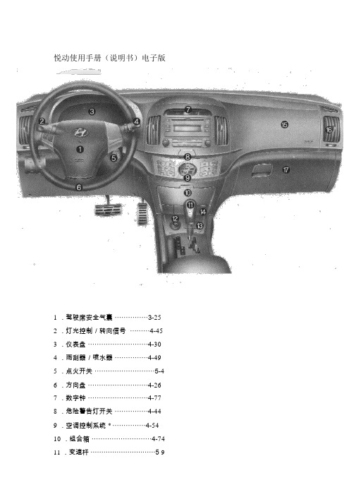
悦动使用手册(说明书)电子版1 .驾驶席安全气囊⋯⋯⋯⋯⋯3-252 .灯光控制/转向信号⋯⋯⋯4-453 .仪表盘⋯⋯⋯⋯⋯⋯⋯⋯⋯4-304 .雨刮器/喷水器⋯⋯⋯⋯⋯4-495 .点火开关⋯⋯⋯⋯⋯⋯⋯⋯⋯5-46 .方向盘⋯⋯⋯⋯⋯⋯⋯⋯⋯4-267 .数字钟⋯⋯⋯⋯⋯⋯⋯⋯⋯4-778 .危险警告灯开关⋯⋯⋯⋯⋯4-449 .空调控制系统 * ⋯⋯⋯⋯⋯4-5410 .组合箱⋯⋯⋯⋯⋯⋯⋯⋯⋯4-7411 .变速杆⋯⋯⋯⋯⋯⋯⋯⋯⋯⋯5-913.AUX⋯⋯⋯⋯⋯⋯⋯⋯⋯4-79 14.烟灰缸⋯⋯⋯⋯⋯⋯⋯⋯⋯ 75 4—15.助手席安全气囊⋯⋯⋯⋯⋯3-25 16.通风口控制⋯⋯⋯⋯⋯⋯⋯4-57 17.手套箱⋯⋯⋯⋯⋯⋯⋯⋯⋯4-73 *:如有配备。
1 .门锁闭锁 / 锁机械操纵⋯⋯4-82 .室外后视镜控制开关 * ⋯⋯4-273 .中央控制门锁操纵开关* ⋯⋯4-94 .电动门窗锁止开关⋯⋯⋯⋯4-166 .行李箱盖释放杆⋯⋯⋯⋯⋯4-127 .保险丝盒⋯⋯⋯⋯⋯⋯⋯⋯7-448 .后雾灯开关⋯⋯⋯⋯⋯⋯⋯4-489 .语音警报系统开关 * ⋯⋯4-4110 .方向盘倾斜杆⋯⋯⋯⋯⋯⋯4-2611 .发动机罩释放杆⋯⋯⋯⋯⋯4-1712 .制动踏板⋯⋯⋯⋯⋯⋯⋯5-1513 .加速踏板⋯⋯⋯⋯⋯⋯⋯⋯⋯5-14 .驻车制动操纵杆⋯⋯⋯⋯⋯5-17 *:如有配备。
悦动自动档使用说明~自动档的使用说起来简单也不简单,说难也不难,很多朋友买了自动档就是为了一 d 到底,自动档确实简单,只要手握方向,眼观八方,工作的事全交给右脚,就能翻山越岭,跋山涉水,无所不去也。
但是我本人作为一个资深工薪族,准备把车保养的好点开个十年的人,还是对这个简单的东西进行了深入的研究,发现自动档的驾驶那是大有学问。
以正常驾驶为例,先说说自动档的分布,咱们悦动的自动波箱由上至下分别为p-r-n-d-3(d 往右边拨下就是) -2-l 。
- 1、下载文档前请自行甄别文档内容的完整性,平台不提供额外的编辑、内容补充、找答案等附加服务。
- 2、"仅部分预览"的文档,不可在线预览部分如存在完整性等问题,可反馈申请退款(可完整预览的文档不适用该条件!)。
- 3、如文档侵犯您的权益,请联系客服反馈,我们会尽快为您处理(人工客服工作时间:9:00-18:30)。
目录一、封面------------------------------------------------------------1二、目录-----------------------------------------------------------2三、主要技术参数-----------------------------------------------3四、使用说明-----------------------------------------------------4五、注意事项-----------------------------------------------------7六、液压系统元件表--------------------------------------------8七、电气元件表-------------------------------------------------8八、台车例行保养----------------------------------------------10九、液压系统安装、维护、使用说明------------------------12十、电气部分简单故障分析----------------------------------13 十一、液压系统原理图-----------------------------------------14 十二、电气原理图----------------------------------------------15 十三、台车装配图----------------------------------------------16主要技术参数1.台车每模衬砌长度:L=9000 mm2.净空尺寸:B×H=14100mm×8103mm3.台车行走速度:6m/min4.单边最小脱模量:180mm5.水平调整量:125mm(单边)6.系统工作压力7.轨中心距:8.油缸最大行程:竖向油缸:侧向油缸:水平油缸:P=12MPa 6600mm±5mm300mm300mm250mm边顶拱式砼衬砌钢模台车使用说明钢模板台车是为各种隧道、涵洞等断面尺寸的混凝土衬砌而专门设计制造的非标产品。
具有立模、脱模功能,衬砌表面光洁度高,衬砌速度快的特点。
钢模板台车的工作过程按以下几步进行:一、检查隧道施工条件是否满足模板台车设计要求:由于模板台车属于非标设备,使用条件必须满足设计要求方可衬砌。
1、检查路面标高及路面状况是否满足设计要求,路面标高:见图所示;路面状况:混凝土路面。
2、检查对地丝杠支撑位置是否满足设计要求,对地丝杠支撑位置:见图所示。
3、检查枕木和钢轨是否满足设计要求;4、检查矮边墙高度是否满足设计要求;5、检查钢模板外表面是否涂抹脱模剂。
二、立模钢模板台车行走至衬砌位置后便可立模,立模前钢模板台车处于脱模状态。
立模按以下几步进行:1、台车至衬砌位置后,收起台架支撑千斤顶,将门架支撑千斤顶撑于钢轨上并旋紧。
2、启动液压电机,操作手动换向阀手柄,使竖向油缸上升。
调整钢模板台车模板,使其接近预定高度;3、操作手动换向阀手柄,使水平油缸平移。
调整钢模板台车模板,使其中心线与衬砌中心线对齐,然后再操作手动换向阀,使竖向油缸上升到预定位置,旋紧台架顶部竖向千斤顶。
4、操作手动换向阀手柄,使侧向油缸撑出。
粗调钢模板台车侧模板至预定位置。
(侧模油缸应单边分别进行)。
5、装好侧向丝杠。
6、关闭电机,来回摇动手动换向阀手柄,使侧向油缸卸压。
调节侧向千斤顶,使钢模板台车侧模板达到灌注状态。
7、装好对地丝杠千斤顶、堵头板。
三、注浆立模完成之后即可进行注浆。
注浆之前,钢模板台车外表面需涂抹脱模剂,以减少脱模时的表面粘力。
注浆输送口包括工作窗口和注浆口。
注浆时,先从钢模板台车模板最下排工作窗口进行注浆,注浆至混凝土快要平齐工作窗口时,关闭工作窗,然后从第二排工作窗口进行注浆,以此类推,最后通过注浆口封顶。
在注浆工作过程中要注意以下几点:1、在每次注浆前,应检查丝杠、千斤顶是否有松动,防止在注浆时台车变形。
2、注浆时,混凝土最大下落高度不能超过3000mm,钢模板台车前后混凝土高度差要求不超过600mm;左右混凝土高度差要求不超过500mm。
3、注浆到最后通过注浆口封顶的后期,必须使用低速档进行注浆,并时刻注意注浆口压力的变化,避免因混凝土注满后强行注入而导致压力过大使模板变形。
四、脱模注浆完成之后,必须让混凝土凝固一定时间后才能进行脱模。
脱模按以下几步进行:1、拆掉侧向千斤顶、对地丝杠千斤顶和堵头板。
2、启动液压系统,操作手动换向阀手柄,控制侧向油缸。
使钢模板台车侧模板脱离衬砌面。
油缸收缩行程为190mm~300mm。
3、收起基础千斤顶。
4、操作手动换向阀手柄,控制竖向油缸。
使钢模板台车钢模板面全部脱离衬砌表面。
油缸收缩时,必须分次收缩,切忌一次性强制脱模。
油缸收缩行程为150mm~250mm。
四、行走钢模板台车脱模之后先收起门架支撑千斤顶,然后旋紧台架支撑千斤顶,启动行走电机即可行走。
钢模板台车行走时要注意以下几点:1、钢模板台车必须完全静止后,才能换向行驶。
2、当轨向坡度过大,而导致台车行驶打滑时,可洒些干细沙到轨面上,以增大粘着力,而使打滑现象消失。
反复循环立模、注浆、脱模、行走这四个工作过程,就完成了钢模板台车的整个作业。
注意事项1、每一个工作循环前要校对钢轨是否平直,钢轨中心距与衬砌中心距是否对齐,检测钢轨牢固性。
台车就位前,一定要把钢轨铺直,严谨防止门架支撑千斤顶不能撑于钢轨上这一现象发生。
2、每一个工作循环后要检查各部位螺栓、销子的松紧状态,对各种联接件重新检查紧固。
3、台车行走机构、丝杆千斤顶要定期打黄油。
4、液压系统应无泄漏现象,液压油应清洁,工作时压力表开关应打开,随时观察压力的波动情况。
5、钢模板台车行走时,边模板下端与地面间不得有风管、水管等障碍物,严防台车行走时有拖带现象。
6、台车浇注前,对地丝杠千斤顶务必顶牢于地面。
7、为了您和他人的安全,请按规范操作台车,并勤于保养,杜绝一切事故发生。
电气部分说明1、必须引入三相四线制电源,否则漏电断路器起不到漏电保护跳闸的作用。
2、配电箱面板上绿色指示灯为电源指示灯。
3、油泵电机热继电器整定电流:11.6A。
液压系统元件表模板台车电气元件表序号名称规格型号单位数量备注1 漏电断路器NM10-100/330-100A 个 12 熔断器RT14 个 23 熔断器芯RT14-20 个 24 接触器JT1-40A/38W 个 25 电机Y132M2-6 台 2 5.5Kw6 热继电器JR36-63 45A 个 17 指示灯AD11 个 38 按扭LA19-11 个 49 配电箱500x400x200 台 1台车例行保养(一级保养每班进行)台车例行保养(二级保养每工作15个循环)台车例行保养(三级保养每工作30个循环)作业项目技术要求及说明一、完成本级保养作业之外的二保项目二、电气控制部分工作电压380V,电压稳定,绝不允许有漏电现象三、液压系统1、更换液压油,滤油器清洗油箱后进行,加抗磨液压油2、调试系统压力(空载下)保证油压达到油泵额定压力四、调试升降油缸底座应平移灵活,最大平移量不得超过80mm附注:一、全液压砼衬砌钢模板台车设计参考书:1、《钢结构设计规范》2、《铁路桥隧道砼及衬砌工程施工技术规则》;二、台车大部分零件为非标件三、整机行走距离短,速度慢,在隧道施工中,若不出现钢结构件变形,无需大修。
液压系统安装、使用、维护说明一、 清点所有部件,应与装箱清单相符。
二、 检察油箱是否清洁,盖好油箱盖,从油箱空气滤清器加入115升清洁的Y A-N46液压油。
三、 按油缸布置要求布管1、焊接管子前应清除干净管子头毛刺、(用圆锉刀),高压风吹净管内杂物。
2、焊接管子应对正对齐,焊牢,不许漏油,3、按布管要求布管,装齐所有密封垫、圈、清理冲冼管内杂物。
4、管路接上多路换向阀和油缸(机械锁油缸必需接在多路换向阀左、右各两片阀上)。
注:胶管则无1、2条。
四、 点动电机检察电机转向,启动油泵试动作各油缸(出厂时压力已经调好)。
如系统压力建立不起来(油缸不动作)应首先检查管子各接头是否漏油,如有应排除。
然后调整溢流阀从压力表上观察压力为12MP即可。
调好后关闭压力表开关,并注意观察油标油位。
五、 经常清洁滤油器滤芯,清除滤芯杂物,堵塞时应更换。
六、 第一次加油后三个循环更换新油,以后视液压油清洁情况不定期更换。
建议三十个循环更换一次新油。
电器部分简单故障分析故障现象原因处理方法电动机不能正常起动1、制电路熔丝已断2、热继电器常闭触点JR未复位3、常闭触点接触不良4、起动与停止按钮间点接触不良或线断1、更换熔丝2、复位触点使之闭合3、修复触点4、接上线,修理按钮点正、反按钮中有一个能控制电机,另一个不能控制电机1、反控制按钮中有一个按钮触点接触不良2、正反控制按钮中有一个互锁常闭触点接触不良1、修复触点2、修复触点、使之闭合正反按钮均不能起动1、反接触器线圈均损坏2、热继电器常闭触点未复位3、检查电源及插头是否松动4、检查停止按钮是否有损坏或其线路是否连通1、更换接触器线圈2、复位垫继电器常闭触点3、检查、更换4、检查、更换。