齿轮锻造工艺设计说明书
传动齿轮轴的加工工艺设计说明书
摘要齿轮轴零件的主要作用是支撑回转零件、实现回转运动并传递转矩和动力。
齿轮轴具备传动效率高、结构紧凑和使用寿命长等一系列优点,是通用机械特别是工程机械传动中的重要零件之一。
齿轮轴加工材料、热处理方式、机械加工工艺过程的优化,将对提高齿轮轴的加工质量及寿命有着重要借鉴意义。
本设计首先分析了齿轮轴零件的作用和零件的材料,之后把加工传动齿轮轴所用的材料和生产类型确定下来。
然后确定毛坯的种类,绘制铸件零件图。
接下来设计零件的加工工艺性,包括零件表面的加工方法及热处理方法等。
最后进行工艺规程设计,选定加工所用的机床,刀具,夹具等。
齿轮轴零件的机械综合性能要求较高,一般选择锻件作为毛坯。
合理安排工艺路线,划分加工阶段对保证零件加工质量至关重要.关键词: 齿轮轴;工艺分析;工艺规程设计AbstractThe main function of the gear shaft is to support rotating parts, achieve rotary mo tion and transfer torque and power. Gear shaft has a series of advantages, such as high transmission efficiency, compact structure, long service life and so on. It is one of the important parts in the general machinery, particularly the engineering machinery tran smission. The optimization of the gear shaft’s machining materials, thermal treatmen t method and machining process will have great significance on the machining quality of the gear shaft and the service life.The first design of the gear shaft parts and parts of the material, then fix the processing gear shaft of the materials used and the type of production. And then determine the blank type, drawing casting parts diagram. The processing of the next design of parts, including the components surface processing method and heat treatment method. Finally, technological process design ,selection of the machine tool, cutting tool, fixture etc…Comprehensive mechanical performance requirements higher gear shaft parts, as general forging blank. Reasonable arrangements for the process, dividing the processing stage is very important to ensure the machining quality of parts.Keywords gear shaft; process analysis; process planning design目录摘要 (I)ABSTRACT (II)第1章绪论............................................................................................................. - 1 -第2章零件的分析 (2)2.1零件的作用 (2)2.1.1零件的作用 (2)2.1.2零件的结构特点及技术要求 (2)2.2零件材料分析 (3)2.3确定生产类型 (3)2.4毛坯的确定 (4)2.5绘制铸件零件图 (4)2.6本章小节 (5)第3章加工工艺过程分析 (5)3.1加工工艺过程的组成 (6)3.2定位基准的选择原则 (6)3.2.1基准的概念 (6)3.2.2 定位基准的选择 (7)3.2.3 定位基准的确定 (8)3.3零件表面加工方法的选择 (10)3.4加工工序安排 (10)3.5热处理工序的安排 (11)3.6工序的划分 (11)3.7加工余量及工序尺寸的确定 (12)3.7.1 加工余量的概念 (12)3.7.2 加工余量的确定方法 (12)3.8本章小结 (13)第4章选择加工设备及工艺设备 (14)4.1各机床的作用 (14)4.1.1车床的作用 (14)4.1.2铣床的作用 (15)4.1.3 磨床的作用 (16)4.1.4 零件加工中各机床的确定 (17)4.2刀具的选择 (17)4.2.1 刀具材料的确定 (17)4.2.2 刀具的分类 (17)4.2.3 常用车刀刀具的用途 (18)4.2.4 铣刀 (19)4.2.5 磨削 (20)4.2.6 加工零件刀具的确定 (20)4.3夹具的确定 (20)4.3.1 夹具的组成及作用 (20)4.3.2 夹具的分类 (21)4.3.3 选择夹具 (22)4.4量具的选择 (22)4.5本章小结 (23)第5章齿轮轴的工艺卡拟定 (24)5.1工艺卡的拟定 (24)5.2问题的提出 (28)5.3本章小结 (29)总结 (30)参考文献 (31)致谢 (32)第1章绪论本文设计的主要是齿轮轴的加工工艺,通过总结零件的的加工,提高所加工工件的质量,完善产品,满足要求,提高经济效益和劳动生产率。
齿轮锻造工艺设计说明书(Gear forging process design manual)
齿轮锻造工艺设计说明书(Gear forging process design manual)Gear forging process design manualAbstract: the purpose of forging blank molding, and control of its internal organizational performance reached the desired geometry, size and quality of forgings, steel and non-ferrous metal and alloy has the most plastic in different degrees, can be plastic molding process in cold or hot. The forging of gears adopts the free forging process. This paper mainly introduces the free forging process of gears. Free forging is the use of pressure or impact force is the metal between the upper and lower iron deformation between plastic deformation, so as to obtain the shape and size of the required method. The determination of free forging becomes the key to free forging. This article focuses on the process of free forging of gears.Keywords: free forging, gear processing, plastic deformation, process flow.CatalogI. introduction............................................... ............. OneTwo. Overall design plan................................................ OneThree. Specific design methods and steps.................................... Three3.1 draw the forging drawing............................................. Three3.2 determine the deformation process.......................................... Three3.2.1 upsetting............................................. Three3.2.2 punching............................................. Four3.2.3 reaming............................................. Four3.2.4 trimming forgings....................................... FourThree3 calculate billet quality and size................................. Four3.4 selection of equipment and specifications (iv)Four. Process flow (process card)....................................... SixFive. Conclusion............................................................ SevenSix. Thanks..................................................... ....... SevenSeven. References................................................. ..... EightManufacturability analysis of forging structureforging drawingParameter selectionDetermination of machining allowance and determination of tolerancesDetermine billet qualityDetermination procedureSelection of forging equipmentDetermination of heating temperature and heating timePost forging heat treatmentThe 1. part drawing process, attached to the instructions, the A4 paper to print or freehand.2. front cover format:1. design specifications must be written, with A4 paper, cover, catalogue, text and references.Advanced design and manufacturing integrated experimentXX part XX process designclassFull nameI. IntroductionThe purpose of forging is to make the blank forming and to control its internal structure to achieve the required geometry, size and quality of the forgings. The basic process of forging is free forging, die forging, sheet metal stamping, in which free forging and die forging are thermoplastic forming, and sheet stamping is cold plastic forming, the basic principle of both is the same.The proportion of forged parts shows the status of a country's production level, productivity, material utilization, production costs and product quality in international competition. Before the founding of new China, forging was basically a continuation of handicraft workshops, with low production efficiency and great labor intensity. However, after the reform and opening up, China's forging technology hasbeen rapid development, which led to the automotive industry, such as leaps and bounds. But we should also clearly see that our forging technology level and European and American developed countries still have a certain gap, which makes us more efforts to develop new technologies, catch up with the international advanced level.Gear is a large number of parts used in modern industry. This paper discusses the free forging production of gears. Free forging can be carried out a lot of processes, can be divided into basic processes, auxiliary processes, and finishing process three major categories. Its basic process is to make the metal produce a certain degree of plastic deformation in order to achieve the desired shape and size of the process, such as upsetting, drawing, punching, bending, cutting, twisting and dislocation and other processes.Two, the overall design1. draw the forging drawingAccording to the basic drawing of parts drawing, combined with the characteristics of free forging, the residual parts, forgings allowance and forging tolerances are drawn.2. calculate billet quality and size(1) calculation of billet quality;According to the shape and size of forging, forging quality can be calculated first, then consider the oxidation loss duringheating, loss of core material and flush cutting head punching, quality first for the calculation of blank forgings, the calculation formula is as followsM billet, =m forging, +m firing, +m head, +m core(2) determination of blank size;The leather size are correlated with the first basic process, because the gear is cake or hollow forgings, with upsetting forging process, in order to avoid upsetting bending, should make the blank height h of not more than 2.5 times the diameter of D, which bases on the ratio of height to diameter less than 2.5 h/D. In order to facilitate operation during cutting, the blank height h should be less than 2.5D, that is, the ratio of height to diameter should be greater than 1.25Diameter of round material.3. choose the forging processGear forging, according to its lateral size greater than or near the height of the characteristics, mainly to upsetting the main, when the forging has a convex shoulder, according to the size of the shoulder pad selection ring, upsetting or partial upsetting. If the forging hole needs to be rushed out, it needs to be punched.4. selected forging equipmentThe selection of forging equipment is based on the material,size and quality of the forgings, as well as the existing equipment conditions of the workshop. If the equipment tonnage is too small, the forging internal is not thorough, the productivity is low, but the equipment and power waste, and the operation is inconvenient and unsafe, usually by empirical analogy or look-up table method.(1) empirical analogyAccording to the empirical formula of hammer tonnage:The upsetting forging hammer tonnage G= (0.002-0.0003) KS (kg)(2) look-up table selectionFor low carbon steel, medium carbon steel and ordinary low alloy steel, the free forging can be checked by the selected tonnage.5. determine the forging temperature and specifications(1) determine the range of forging temperatureThe forging temperature range of all kinds of alloy steel can be found from the table. The basic principle is to ensure that the steel has good plasticity and low deformation resistance in the range of forging temperature, and can forge high quality forgings,And a wide range of forging temperature and less heating times, as well as higher productivity.(2) determine the range of heating and coolingFor the carbon structural steel with a good thermal conductivity and a diameter of less than 150~200mm, a section of heating code shall be adopted, and the furnace shall be controlled at a temperature of 1300 ~1350 c.. When the billet is heated to the initial forging temperature, it is immediately baked and forged.(3) determination of cooling methods and specifications;Choose air cooling, pit cooling or furnace cooling as required. Small and medium carbon steel and low alloy steel are forged by air cooling method with faster cooling rate. Carbon tool steel, alloy tool steel and bearing steel, forged, air cooled, blown, or sprayed quickly to 200 degrees, then put the forgings into a pit or cooled in a furnace.Three, the specific design methods and steps1. draw parts drawingThe material of this part is 40Cr, and the production is small in quantity. The gear blanks are forged by free forging.The gear on the circumference of the small groove shoulder and 8 x 30mm diameter hole part, the free forging method is very difficult to form these parts, considering the feasibility and economy of technology, and decided not forged, and the additional block shape to simplify the forging, forging. After forging the gear blank, it can be further processed and finallyAccording to the dimension of the parts drawing, the height and the diameter of the parts listed in the comparison table, the allowance and tolerances for the machining of the gear forgings can be found out. D=289, h=52, machining allowance and tolerance check for horizontal forging forging height direction a=10 + 4, b=9 + 3, c=13 + 5 hole bilateral, and press check tolerances can be drawn numerical Shoulder Gear Forging drawing.Forging drawing is given separately.2. determine the deformation processConvex shoulder shaped gear forgings belongs to the hollow part, according to the shape and size of forgings, forging in the forging hammer, and the main deformation process for upsetting and punching, punch reaming process, the auxiliary cushion ring upsetting forming is determined according to the forging of the shoulder shape.At present, these kinds of short swords generally use partial upsetting, while upsetting forming is suitable for shoulder forgings with small diameter and height. Because the gear diameter is larger, so we decide to use the punch reaming, but considering the punching metal will flow along the radial hole, and along the height direction of the shoulder pulling shrinkage phenomenon, so that the cushion ring upsetting after the diameter size should be smaller than the diameter of the forging, and shoulder height should be greater than the forging(1) upsettingSince the forgings are single sided, the pad ring shall be upset, and the ring size shall be determined here.Cushion ring cavity volume V pad should be more than the volume of the forging shoulder volume V, shoulder big 10% - 15% (thick wall take small value, thin wall take big value), this case take 12%, calculate V shoulder =753253mm3. beV pad = (1+12%) V shoulder =1.12 * 753253=843643 mm3Taking into account the hole will produce shrinkage, cushion ring height H pad should be increased by 15% to 30% than the convex shoulder (thick wall take small value, thin-walled take big value), this example take 20%.H pad, =1.2H shoulder, =1.2 * 34=40.8 (mm), take 40mm. The inner diameter of the cushion ring D pad can be inconvenient to obtain according to the volumeThe inner wall of the cushion ring should have a slope of 7 degrees, and the upper aperture shall be 163mm, and the lower end aperture shall be 154mm.In order to remove the oxide, the flat anvil upsetting shall be carried out before the pad ring upset, and the process is shown as shown in fig.. After upsetting the flat anvil, the diameter of the billet should be slightly smaller than the innerdiameter of the gasket ring, and the diameter of the upper flange at the upper flange shall be smaller than the maximum diameter of the forging ring after upsetting.(2) punchingPunching punching should make the core material loss is small, while expanding the number of not too much, D punching hole diameter should be less than or equal to D/3 or D at less than D/3=213/3=71mm, the practical use of d=60mm.(3) reaming;The total reaming amount is the hole diameter of the forging minus the punching diameter, that is, (131-60) =71mm, the amount of reaming is 25~30mm in general, and the amount of reaming is 21mm, 25mm and 25mm respectively.(4) trimming forgingsTrim according to the forging drawing.3. calculate billet quality and sizeThe quality of the billet is equal to the quality of the forging, plus the quality of the core and the quality of burning. The quality of the forgings is calculated according to the formulaM forging =V forged P = Pi /4 (32 * 0.27+2.112 * 0.34+1.322 * 7.8=17.8kg * 0.61)Quality of punched core material (take d=60mm, H=65mm) asM core = (1.18~1.57) D2 * H=0.3kgThe gas furnace heating billet loss rate u =2%, considering the need of forging after 2~3 reaming, and requires at least 2 heating, therefore should take the upper limit of single fire damage rate plus appropriate loss value is =0.035, so the quality of the billet is burningM burn =17.8 * 0.035kg=0.6kgTherefore, the quality of the blank isM billet, =m forging, +m firing, +m head, +m core, =18.7kgWhen calculating the diameter of the blank, the die can be calculated by upsetting:Table look-up shows that the diameter of standard hot rolled round bar is determined by the diameter of the selected billet D=120mm.Billet lengthThus, the blank size is determined to be Phi 120 * 210mm.4. selection of equipment and specificationsThe forging type belongs to the ring, D=289, H=52, the look-up table should be used 5kN hammer. 40Cr is an alloy structuralsteel. The temperature of the starting forging is 1200 degrees and the final forging temperature is 800 degrees. Because of the forging is the diameter of 200~350mm medium carbon structural steel, the three stage gas furnace heating specification, charging temperature of 1150 DEG ~1200 DEG, the holding time is about the total heating time (1h~100min) 5%~10%, here is 15min with maximum insulation, heating speed is heated to 1200 DEG C after thermal insulation again about 15min after the start of forging.Cooling method: the forging is a kind of medium and low alloy structural steel, and it can be cooled by air cooling.Four 、 process flow (process card)Forging name, gear (forging drawing shall be given separately)Forging material 40CrBillet quality 18.7kgBlank Size 120 * 210mm0.5T free forging hammer forging equipmentSchematic diagram of fire operation procedure1 blankingThe quality and size of the billet can be calculated from the forging drawing at phi 120 * 210mmUpsettingLocal upsetting of cushion ringH pad =40mm,D pad =164mm2 punchingD Chong =60mmPunch reamingIt is divided into three reaming, and each reaming amount is 21mm, 25mm, 25mmDressingTrim according to the forging drawingFive. ConclusionBy using the above process, the gear blanks can be forged, and then the gears can be produced as long as the cutting process is formed. I think why not directly machining, but advanced forging it? The reason must be that forging can not only make its initial shape, but more importantly, forging can improve the mechanical properties of parts and improve its toughness and strength. Therefore, the key parts of the key parts shouldbe forged first, then cut into shape.Six, thanksThrough this hot processing course design, I deeply understand the importance of hot processing in industrial production. I do is the forging process design of gear, the process of gear machining are deeply discussed, which let me learn a lot, and I will be more efforts to improve and perfect their knowledge, to face greater challenges in future work. In this course design, XXX teacher gave me great help, thank you once again, but also to thank my own efforts of these days, the sweat will be watered out of successful flowers.Seven. References[1] Wang Aizhen, foundation of hot working technology, Beijing, Beihang University press[2] Wang Aizhen, metal forming process design, Beijing, Beihang University press[3] Hu Yamin, forging process and die design, Beijing, Peking University press。
齿轮锻造工艺设计_课程设计说明书
课程设计说明书齿轮锻造工艺设计摘要:本次课程设计说明了齿轮的锻造工艺,同时论述了齿轮零件的锻造工艺设计是一个涉及诸多综合性因素的问题,它与所选的制造机械零件材料的性能、制造的工艺过程、生产的现场条件、生产批量及经济性等因素有密不可分的关系。
只有了解了锻造的工艺要求和热处理的规范,以及选择合适的设备,才能完成齿轮的锻造。
目录一.绘制锻件图................................................. - 1 -1.确定锻件形状.............................................. - 1 -2.确定加工余量.............................................. - 1 -3.确定锻造公差.............................................. - 1 -4.绘制锻件图................................................ - 2 -二.确定锻造工艺............................................... - 3 -1.锻件分类及工序............................................ - 3 -2.制定变形工艺方案.......................................... - 3 -3.确定合适的锻比............................................ - 4 -三.确定毛坯的质量和尺寸....................................... - 5 -1.毛坯质量计算.............................................. - 5 -2.毛坯尺寸确定.............................................. - 6 -四.选定锻造设备及吨位......................................... - 7 -1.查表选定法................................................ - 7 -五.确定锻造温度及规范......................................... - 8 -1.确定锻造温度范围.......................................... - 8 -2.确定加热规范及火次........................................ - 8 -3.确定冷却方法.............................................. - 9 -4.确定冷却规范.............................................. - 9 -5.确定热处理规范............................................ - 9 -六.设计总结.................................................. - 10 - 致谢......................................................... - 11 - 参考文献..................................................... - 12 - 工艺卡....................................................... - 13 -一.绘制锻件图绘制锻件图是拟定锻造工艺规程、选择工具、指导生产和验收锻件的主要依据。
齿轮轮芯锻造课程设计
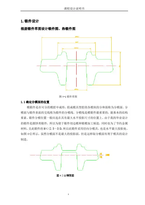
1.锻件设计根据锻件草图设计锻件图、热锻件图图4-1锻件草图1.1确定分模面的位置模锻件是在可分的模腔中成形,组成模具型腔的各模块的分和面称为分模面。
分模面与锻件表面的交线称为锻件的分模线。
分模线是模锻件最重要的,最基本的结构要素。
锻件分模位置一般应选在具有最大水平投影尺寸的位置上。
由于我的毕业设计的锻件是圆饼类锻件,所以为便于锻件切边模和锻模加工制造,同时也为了节约金属材料,且此锻件的H≤(2.5~3)D,所以此锻件采用径向分模具,也是水平最大投影处。
如图4-2所示,虽然分模面不是最大的投影面,但是这样取分模面有利于模具的设计制造。
图4-2分模简图1.2确定拔模斜度为便于模锻件从型槽中取出,必须将型槽壁部做一定的斜度,称为模锻斜度或出模角。
模锻斜度可以是锻件侧壁附加的斜度,也可以侧壁的自然的斜度。
斜度越大,取出锻件越容易。
但是,增大斜度会增加金属的消耗和机械加工余量,而且使金属充满型槽发生困难。
因此,在保证锻件能顺利出模的前提下,应尽量减小模锻斜度。
由于此锻件是回转体类锻件,所以,按公式:h/2r 来确定斜度。
图4-3锻件h1/r1=50/6=8.3 h2/r2=8/6=1.3 按 表4-5-c 查得模锻斜度分别为7︒和5︒。
为方便,拔模斜度全部采用7 ,如图4-3所示。
1.3确定公差确定锻件机械加工余量和公差的大小的方法主要有两种:一是按锻锤吨位大小确定;另一中方法是按锻件的形状尺寸大小来查表确定;在这里用第二中方法。
由初步造型得出锻件体积为272850223d v mm =,其外轮廓包容体的体积为33.14366366366153947593.44b v m m =⨯⨯⨯=,从而可初步得出锻件形状复杂系数728502230.473153947593.44d b v s v === 由锻件形状复杂系数查 表4-3得其形状复杂程度为一般系数,代号2s ,根据所给任务书得锻件材料为42CrMo ,由锻件的体积以及材料密度得出锻件的质量:3728502237.85/571874571.91000d m v g cm g kg ρ=⨯=⨯=≈根据锻件质量m 、锻件形状复杂系数2s 、锻件的相关尺寸及零件表面粗糙度查[5]表4-3得出机械加工余量查出为1.7 2.2,取最大值2mm ;根据材质系数1M 、形状复杂系数2s 、锻件质量m 以及锻件的相关尺寸查 表4-5,并且以同类中的最大公差为最后公差得:宽度公差 1.10.51.6+- 高度公差 0.90.51.4+- 错差公差 0.6 残留飞边公差 0.6根据材质系数1M 、形状复杂系数2s 、锻件质量m 以及锻件的相关尺寸查[5]表4-7,并且以最大公差为最后公差得: 厚度公差 1.20.41.6+- 。
齿轮设计说明书
重庆大学本科学生课程设计零件齿轮的工艺规程设计学生:何XX学号:2XX指导教师:XXX专业:机械电子工程重庆大学机械工程学院二0一七年十二月目录重庆大学本科学生课程设计任务书 (3)1. 序言 (4)2. 零件分析 (4)2.1. 零件的作用 (4)2.2. 零件的工艺分析 (4)3. 基准的选择 (4)3.1. 定位方式 (4)3.1.1. 带轴齿轮的定位方式 (4)3.1.2. 以内孔和端面定位 (5)3.1.3. 以外圆和端面定位 (5)3.2. 零件的技术条件 (6)3.2.1. 零件的表面粗糙度和加工精度 (6)3.2.2. 各表面的位置精度(略) (6)3.2.3. 零件表面的加工方法 (6)4. 工艺规程的设计 (7)4.1. 毛坯的确定 (7)4.1.1. 确定机械加工余量 (8)4.1.2. 确定毛坯尺寸公差 (8)4.1.3. 确定圆角半径 (8)4.1.4. 确定拔模斜度 (9)4.1.5. 确定分模位置 (9)4.1.6. 确定毛坯的热处理 (9)4.2. 制定工艺路线(见机械加工工艺过程卡片) (9)4.2.1. 粗铣 (9)4.2.2. 精铣 (9)4.2.3. 粗车 (9)4.2.4. 粗车 (9)4.2.5. 拉孔 (9)4.2.6. 滚齿 (9)4.3. 重点工序的说明(见工序卡片) (10)5. 各工序切削用量的选择热处理工艺及工时的计算 (10)5.1. 工序1(略) (10)5.2. 工序2(略) (10)5.3. 工序3(略) (10)5.4. 工序4:见工序卡片 (10)5.4.1. 切削用量 (10)5.4.2. 工时的计算 (10)6. 设计心得体会 (11)重庆大学本科学生课程设计任务书1.序言机械制造课程设计是在学完了机械制造技术基础和部分专业课,并进行了生产实习的基础上进行的一个教学环节。
这次设计使我们能综合运用机械制造工艺学中的基本理论,并结合生产实习中学到的实践知识,独立地分析和解决工艺问题。
双齿轮锻造工艺说明书

双齿轮锻造工艺设计说明书一、分析零件图(如图)ⅡⅠ1.61.60.81.652h915°10°701、零件名称:双齿轮;2、材料:40Cr ;3、质量:1kg ;4、产量:100件;5、技术要求:热处理,齿部G52 6、齿轮基本参数:1)m=4;2)z=20, 精度等级8-8C 、7-7C 3)α=20°。
二、锻造工艺性分析首先,运行计算机辅助自由锻锻件工艺设计软件,进入用户界面。
在主菜单中,选择"工艺方法分析"子菜单。
点击后进入"工艺方法分析"界面,此时,对零件可进行结构分析,缺陷分析,零件作用分析。
对零件的锻造工艺性分析完成后,点击"返回",系统则回到计算机辅助自由锻锻件工艺设计软件的主界面。
下面是双齿轮B1的锻造工艺性分析结果: 1、加工目的、环境及锻后现象分析零件为齿轮类零件,因此锻造的目的不是侧重于成形、减少加工余量,而是侧重于提高锻件的力学性能。
结合现代工厂设备、技术力量和加工能力,选用自由手工锻造。
锻后零件性能可能变化的趋势有坯料端部弯曲并带毛刺和脱碳等。
2、零件结构形状对锻造适应性的分析即锻件结构工艺性分析。
该零件为简单的齿轮类零件,可通过手工自由锻造来完成初步成型。
因锻造而产生的缺陷可以通过锻造后的热处理和切削加工来改善。
在锻造时,由于锻件本身的成分、组织的不均匀和各处受力情况不同,锻件内各处的变形情况也不同,变形首先发生在那些先满足屈服准则的部分。
因此,有的地方先变形,有的地方后变形;有的地方变形大,有的地方变形小,由于存在变形的不均匀性,将在个部分变形金属之间产生相互影响,产生附加应力(例如在镦粗时坯料侧表面切向产生的附加拉应力等)和残余应力等,带来一些不良的影响。
所以在锻造时要注意以下几方面:1),为防止镦粗时产生纵向弯曲,圆柱体坯料高度与直径之比不应超过 2.5~3,在2~2.2的范围内更好。
齿轮工艺课程设计说明书
目录1.序言 12.零件的工艺分析与生产类型的确定 12.1零件的作用 12.2零件的工艺分析 22.3零件的生产类型 23.选择毛坯,确定毛坯尺寸,设计毛坯图 33.1确定毛坯制造形式 32.确定机械加工余量 33.3确定毛坯尺寸 43.4确定毛坯尺寸公差 43.5设计毛坯图 54.选择加工方法,制定工艺路线 64.1定位基准的选择 64.2零件表面加工方法的选择 64.3制定工艺路线 75.工序设计 85.1选择加工设备与装备 85.2确定工序尺寸 116.确定切削用量与基本时间 146.1工序I切削用量与基本时间的确定 146.2工序Ⅱ切削用量与切削时间的确定 18 6.3工序Ⅲ切削用量与基本时间的确定 19 6.4工序Ⅳ的切削用量与基本时间的确定 21 6.5工序Ⅴ切削用量与基本时间的确定 22 6.6工序Ⅵ切削用量与基本时间的确定 23 6.7工序Ⅶ切削用量与基本时间的确定 25 6.8工序Ⅷ切削用量与基本时间的确定 25 7.夹具设计 267.1定位方案 267.2夹紧机构 267.3对刀装置 277.4夹具与机床连接元件 277.5夹具体 277.6使用说明 277.7结构特点 27总结参考文献1.序言课程设计在我们学完大学的全部基础课、专业基础课之后进行的,这是我们在进行课程设计对所学各课程的深入综合性的总复习,也是一次理论联系实际的训练,因此,它在我们的大学生活中占有重要的地位。
另外在做完这次课程设计之后,我得到一次在毕业工作前的综合性训练,我在想我在下面几方面得到了锻炼:运用机械制造工艺学课程中的基本理论以与在生产实习中学到的实践知识,正确地解决一个零件在加工中的定位,夹紧以与工艺路线安排,工艺尺寸确定等问题,保证零件的加工质量。
提高结构设计能力。
通过设计夹具的训练,获得根据被加工零件的加工要求,设计出高效,省力,经济合理而能保证加工质量的夹具的能力。
学会使用手册以与图表资料。
齿轮零件加工工艺设计说明书
齿轮零件加工工艺设计课程作业机械加工工艺课程设计第一次作业班级组别机设1311 第一组指导老师蔡海涛组长王亚铭组员王亚铭尹益强林祖汉于思编制尹益强王亚铭2015年3月16日目录1 计算生产钢领,确定生产类型 (4)2 审查零件图样的工艺性 (5)3 选择毛胚 (6)4 工艺过程设计 (7)4.1 定位基准的选择 (7)4.2零件表面加工方法的选择 (7)4.3 制定工艺路线 (9)5 确定机械加工余量及毛培尺寸,设计毛培图 (10)5.1 确定机械加工余量 (10)5.2确定毛培尺寸 (10)5.3 设计毛培图 (11)6 工序设计 (15)6.1 选择加工设备与工艺装备 (15)6.2确定工序尺寸 (18)7 确定切削用量及基本事件(机动时间) (24)7.1 工序30切削用量及基本时间的确定 (24)7.2工序40切削用量及基本时间的确定 (29)7.3工序60切削用量及基本时间的确定 (29)7.4 工序70切削用量及基本时间的确定 (32)7.5 工序80切削用量及基本时间的确定 (33)7.6 工序90切削用量及基本时间的确定 (34)7.7 工序100切削用量及基本时间的确定 (36)7.8 工序110切削用量及基本时间的确定 (38)8 三维造型图 (39)附件一丶零件图二丶机械加工工艺过程卡三丶机械加工工序卡四丶零件检验卡1 计算生产纲领,确定生产类型图7.1—1所示为某产品上的一个齿轮零件。
该产品年产量为2000台,设其备品串为10%,机械加工废品串为1%,现制订该齿轮零件的机械加工工艺规程。
N=Q n(1+α%十β%)=8000 X1(1十5%十1%) 件/年=8480件/年齿轮零件的年产旦为2220件,现已知该产品届于轻型机械,根据表1.1-2于生产纲领的关系,可确定其生产类型为中批生产。
2 审查零件图样的工艺性齿轮零件图样的视图正确、完整,尺寸、公差及技术要求齐全。
但基推孔Φ68K7m m要求Ra o.8μm有些偏高。
轴齿轮的机械加工工艺及工装设计说明书
内容摘要:我们通过对零件进行工艺分析,选择合理的毛坯外形与尺寸。
根据粗基准、精基准的选择原则,选择正确的定位基准和加工顺序,选择和计算加工余量,制定工艺路线,通过分析比较各工艺路线的优点与不足,选择合理的工艺路线。
查找、分析、计算各工序的切削用量,进给量及切削速度,计算工时。
对齿轮的加工进行了夹具设计,通过分析零件加工的工艺性,确定定位、夹紧方案,对定位误差、夹紧力进行了简单计算。
关键词:轴齿轮、加工工艺、工序、夹具目录一.零件的工艺分析 (5)二. 毛坯的确定 (5)三.零件的基准选择 (6)四.重点工序的说明 (7)五.工艺路线分析比较 (7)六.加工余量的确定 (8)七.各工序切削用量的选择及工时的计算 (10)八.专用夹具的设计 (22)九.参考文献 (25)一.零件的工艺分析1.零件的结构特点:题目所给的零件是一个轴齿轮,一端加工出一个Φ52.5、齿数为19、模数是2.5的齿轮。
另一端是一个连续的短轴径有一个键槽和另外一个零件进行配合。
在齿轮的一端加工一个Φ28长度为17的孔,另一端也要加工Φ32长为44精度要求比较高的孔,在孔的一侧还要加工一个油槽。
具体形状如图1-1所示.图1-1 加工零件2.技术要求(1).轴的内圆与外圆的圆跳度不大于0.03。
(2).毛坯要经过调至热处理,提高力学性能。
(3).齿部表面要进行淬火处理,硬度为HRC45-48。
3.加工工艺性此零件的技术要求不高,用车床、镗床、铣床、插床就可以加工出。
精度要求一般是7级或8级,而且表面粗糙度也要求不高,是一个较好加工的零件。
二. 毛坯的确定从轴的受力分析可知,它受扭转——弯曲复合作用力,由于其承受中等载荷,工作又较平稳,冲击力很小,所以可采用优质结构钢的45号钢,坯料用热轧圆钢。
为了改善组织,提高力学性能,坯料要经过正火热处理。
由于热轧钢是从炼钢厂直接出来的,所以尺寸是固定的。
轴的精度要求不高,精车就可以达到要求。
在车外圆采用粗车——半精车——精车的加工工艺。
齿轮锻造工艺说明书
编号课程设计说明书题目齿轮零件锻造工艺及模具设计二级学院材料科学与工程学院专业材料成形及控制工程班级学生姓名廖本洪指导教师夏华时间19-20周目录绪论241.1零件分析 (4)452.3 确定锻件模锻斜度 (8)8993 锤用锻模设计 (10)3.1 设备吨位的确定03.2 选择飞边槽01224 锤上模锻工艺设计 (12)2236167锻前加热锻后冷却及热处理要求的确定 (17)78888 确定模具材料及热处理的要求 (18)1101绪论锻造是一种借助工具或模具在冲击或压力作用下加工机械零件或零件毛坯的方法。
与其它加工方法相比,锻造加工生产率高;锻件的形状,尺寸稳定性好,并具有最佳的综合力学性能。
锻件的最大优势是韧性高,纤维组织合理,件与件之间性能变化小;锻件的内部质量与加工历史有关,不会被任何一种金属加工工艺超过。
锻造生产根据使用工具和生产工艺的不同而分为自由锻、模锻和特种锻造。
自由锻造:一般是指借助简单工具,如锤,砧,型砧,摔子,冲子,垫铁等对铸锭或棒材进行镦粗,拔长,弯曲,冲孔,扩孔等方式生产零件毛坯。
加工余量大,生产效率低;锻件力学性能和表面质量受生产操作工人的影响大,不易保证。
这种锻造方法只适合单件及极小批量或大锻件的生产;不过,模锻的制坯工步有时也采用自由锻。
特种锻造:有些零件采用专用设备可以大幅度提高生产率,锻件的各种要求也可以得到很好的保证,特种锻造有一定的局限性,特种锻造机械只能生产某一类型的产品,因此适合于生产批量大的零部件。
模锻:模锻是指将坯料放入上下模块儿的模膛间,借助锻锤锤头,压力机滑块或液压机活动横梁向下的冲击或压力成形为锻件。
锻模的上下模块分别紧固在锤头和底座上。
模锻件余量小,只需少量的机械加工(有的甚至不加工)。
模锻生产效率高,内部组织均匀,件与件之间的性能变化小,形状和尺寸主要靠模具保证,受操作人员的影响小。
锻造应用范围广,几乎所有的运动的受力部件都由锻造成形,大到飞机轮船小到我们生活中的日常用品,锻造是现代工业的重要组成部分,同时也推动现代工业的不断向前发展。
- 1、下载文档前请自行甄别文档内容的完整性,平台不提供额外的编辑、内容补充、找答案等附加服务。
- 2、"仅部分预览"的文档,不可在线预览部分如存在完整性等问题,可反馈申请退款(可完整预览的文档不适用该条件!)。
- 3、如文档侵犯您的权益,请联系客服反馈,我们会尽快为您处理(人工客服工作时间:9:00-18:30)。
齿轮锻造工艺设计说明书姓名:xxx学号:xxxxxxxx班级:xxxxxxx日期;xxxxxxx齿轮锻造工艺设计说明书摘要:锻造生产的目的是坯料成型、及控制其内部组织性能达到所需的几何形状,尺寸以及品质的锻件,钢和大多数非铁金属及合金具有不同程度的塑性,均可在冷态或热态下进行塑性加工成型。
齿轮的锻造采用的是自由锻工艺。
本文主要介绍的是齿轮的自由锻工艺。
自由锻是利用压力或冲击力是金属在上下抵铁之间产生塑性变形,从而获得所需锻件形状及尺寸的方法。
确定自由锻的工艺成为了自由锻加工的关键。
本文着重介绍的就是齿轮的自由锻的工艺流程。
关键词:自由锻、齿轮加工、塑性变形、工艺流程。
目录一.绪论 (1)二.总体设计方案 (1)三.具体的设计方法与步骤 (3)3.1绘制锻件图 (3)3.2确定变形工艺 (3)3.2.1镦粗 (3)3.2.2冲孔 (4)3.2.3扩孔 (4)3.2.4修整锻件 (4)3.3计算坯料质量和尺寸 (4)3.4选定设备及规范 (5)四.工艺流程(工艺卡) (6)五.结论 (7)六.致谢 (7)七.参考文献 (8)一、绪论锻造的目的是使坯料成形及控制其内部组织性能达到所需的几何形状,尺寸以及品质的锻件。
锻造的基本工艺有自由锻、模锻、板料冲压等,其中自由锻和模锻是热塑性成型,而板料冲压是冷塑性成形,两者的基本原理相同。
锻造件占得比例说明了一个国家生产水平、生产率、材料利用率、生产成本及产品品质在国际竞争中的地位。
在新中国成立之前,锻造基本上是手工作坊式的延续,生产效率低,劳动强度大。
然而在改革开放之后我国的锻造工艺水平得到了迅猛的发展,从而带动了诸如汽车工业的跨越式发展。
但我们还应该清醒的看到我们的锻造工艺水平与欧美发达国家还有一定差距,这更加促使我们努力发展新技术,赶超国际先进水平。
齿轮是现代工业大量使用的零件,本文就是讨论齿轮的自由锻生产。
自由锻能进行的工序很多,可分为基本工序、辅助工序、及精整工序三大类。
它的基本工序是使金属产生一定程度的塑性变形以达到所需的形状和尺寸的工艺过程,如镦粗,拔长、冲孔、弯曲、切割、扭转及错移等工序。
二、总体设计方案1.绘制锻件图根据零件图的基本图样,结合自由锻工艺特点考虑余块、锻件余量和锻造公差等因素绘制而成。
2.计算坯料质量及尺寸(1)坯料质量的计算根据锻件的形状和尺寸,可先计算锻件的质量,再考虑加热时的氧化损失,冲孔时冲掉的芯料以及切头的损失,可先计算锻件所用的坯料的质量,其计算公式为m坯=m锻+m烧+m头+m芯(2)坯料尺寸确定皮料尺寸与所用第一个基本工序有关,由于齿轮是饼块类或空心类锻件,用镦粗工序锻造时,为了避免镦弯,应使坯料高度h不超过直径D的2.5倍,即坯料高径比h/D不超过2.5。
为了在截料时便于操作,毛坯高度h不仅应小于2.5D,即高径比还应大于1.25即≤.1≤25DhD5.2圆料直径()≥。
D38.0dmV坯3.选择锻造工序齿轮的锻造,根据其横向尺寸大于或近于高度的特点一般以镦粗为主,当锻件有凸肩时,可按凸肩尺寸选垫环镦粗促或局部镦粗。
若锻件孔需冲出还需采取冲孔。
4.选定锻造设备选定锻造设备的依据是锻件材料、尺寸和质量,同时还要适当考虑车间现有设备条件。
若设备吨位太小,锻件内部锻不透,生产率也低,反则造成设备和动力的浪费,且操作不便也不安全,通常按经验类比法或查表法等确定。
(1)经验类比法锻锤吨位可按经验公式计算:镦粗时锻锤的吨位G=(0.002-0.0003)KS(kg)(2)查表选定法对于低碳钢、中碳钢和普通低合金钢的自由锻可查表选定吨位。
5.确定锻造温度及规范(1)确定锻造温度范围各类合金钢的锻造温度范围可以从表中查出,基本的原则是确保钢在锻造温度范围内具有良好的塑性和较低的变形抗力,能够锻造出优质锻件,且较宽的锻造温度范围和较少的加热次数,以及较高的生产率。
(2)确定加热及冷却范围对于导热性好,直径小于150~200mm的碳素结构钢小件,采用一段加热规范,一般高温装炉,炉温控制在1300℃~1350℃。
当坯料加热至始锻温度后,立即出炉锻造。
(3)确定冷却方法及规范根据要求选择空冷、坑冷或炉冷。
中小型碳钢和低合金钢锻后均采取冷却速度较快的空冷方法。
碳素工具钢、合金工具钢及轴承钢,锻后先空冷鼓风或喷雾等快速冷到200℃,然后把锻件放入坑中或炉中缓冷。
三、具体的设计方法与步骤1.绘制零件图该零件材料为40Cr,生产批量小,采取自由锻锻造齿轮坯。
齿轮上的齿形,圆周小凹槽,凸肩以及8×φ30mm通孔等部分,采用自由锻方法很难成形这些部位,因此考虑到技术上的可行性和经济性,决定不与锻出,并采用附加余块简化锻件外形,以利于锻造。
锻造出齿轮坯后可以进一步进行切削加工,最后成形。
根据零件图的尺寸规格,对照表所列中零件的高度和直径范围,可以查出齿轮锻件加工余量和公差。
D=289,h=52,查得的加工余量及公差为锻件水平方向a=10±4,锻件高度方向b=9±3,内孔的双边c=13±5,然后按查得的公差数值,便可绘出凸肩齿轮的锻件图。
锻件图另行给出。
2.确定变形工艺凸肩形齿轮锻件属于空心零件,根据锻件形状尺寸,确定在锻锤上进行锻造,且主要变形工艺为镦粗、冲孔、冲头扩孔等工序,同时根据锻件上的凸肩形状确定采用垫环辅助局部镦粗成型。
目前这类短剑一般采用局部镦粗,而镦挤成形则适于直径和高度均较小的凸肩锻件。
由于齿轮内径较大,因此确定采用冲头扩孔,但考虑到冲孔扩孔时金属将会沿着径向流动,并沿着凸肩高度方向产生拉缩现象,因此垫环镦粗后的外径尺寸应比锻件外径小些,且凸肩高度应比锻件凸肩大些。
(1)镦粗由于锻件带有单面凸肩,需采用垫环镦粗,这里要确定垫环尺寸。
垫环孔腔体积V垫应比锻件凸肩体积V肩大10%—15%(厚壁取小值,薄壁取大值),本例取12%,经计算V肩=753253mm3。
则V垫=(1+12%)V肩=1.12×753253=843643 mm3考虑到冲孔是会产生拉缩,垫环高度H垫应比凸肩增大15%—30%(厚壁取小值,薄壁取大值),本例取20%。
H垫=1.2H肩=1.2×34=40.8(mm)取40mm。
垫环内径d 垫可根据体积不便求得,即 mm164H V 13.1≈=垫垫垫d垫环内壁应有斜度7度,上端孔径定为163mm ,下端孔径定为154mm 。
为了除去氧化皮在垫环镦粗之前应进行平砧镦粗,工艺过程如图。
平砧镦粗后坯料的直径应略小于垫环内径,经垫环镦粗后上端法兰部分直径应小于锻件最大直径。
(2) 冲孔冲孔应使冲孔芯料损失小,同时扩孔次数不能太多,冲孔直径d 冲应小于或等于D/3即d 冲≤D/3=213/3=71mm,实际选用d=60mm 。
(3) 扩孔总扩孔量为锻件孔径减去冲孔直径,即(131-60)=71mm,一般每次扩孔量为25~30mm ,分配各次扩孔量为21mm 、25mm 、25mm 。
(4) 修整锻件 按锻件图进行修整。
3. 计算坯料质量和尺寸坯料质量等于锻件质量加上芯料质量和烧损质量,锻件质量按公式计算为m 锻=V 锻ρ=π/4(32×0.27+2.112×0.34+1.322×0.61) ×7.8=17.8kg冲孔芯料的质量(取d=60mm ,H=65mm )为 m 芯=(1.18~1.57)d 2×H=0.3kg坯料的煤气炉加热的烧损率δ=2%,考虑到该锻件需要经过2~3次扩孔,而至少需要加热2次,因此应取单火烧损率的上限再加上适当的烧损值,即为δ=0.035,所以坯料的烧损质量为m 烧=17.8×0.035kg=0.6kg 所以坯料的质量为m 坯=m 锻+m 烧+m 头+m 芯=18.7kg计算坯料的直径时,由于采用镦粗成形,可按下式计算:mm120dm 2.1dm 85.77.189.0m 9.09.0333=====ρ坯坯V D查表可知标准热轧圆钢直径,确定选取坯料直径D=120mm 。
坯料长度为mm210mm 12041038.2S 26=⨯⨯==π坯坯V L从而确定坯料尺寸为φ120×210mm 。
4. 选定设备及规范该锻件类型属于圆环,D=289,H=52,查表可知应选用5kN 的自由锻锤。
40Cr 属于合金结构钢,查表可知始锻温度为1200℃,终锻温度为800℃。
因为该锻件是直径为200~350mm 的碳素结构钢中型件,采用煤气炉三段式加热规范,装料炉温为1150℃~1200℃,保温时间约为总加热时间(1h~100min )的5%~10%,这里保温为15min ,再以最大加热速度加热至1200℃以后,再次保温均热约为15min 后开始锻造。
冷却方法:以为该锻件是中小型低合金结构钢,可以采取空冷的冷却方式。
四、工艺流程(工艺卡)五、结论采用以上工艺可以锻造出齿轮坯,之后只要在进行切削加工成形就能制造出齿轮了。
我想为什么不直接进行切削加工而是先进性锻造呢?其原因一定是锻造不仅能使其初步成形而且更重要的是锻造可以改善零件的力学性能,提高它的韧性与强度。
所以关键部分的重要零部件都要先进行锻造然后切削成形。
六、致谢通过这一次的热加工课程设计,我深刻的领会到了热加工在工业生产中的重要地位。
我做的是齿轮的锻造工艺设计,对齿轮加工的各个过程进行了全面深入的讨论,这让我从中学到了很多,我以后也会更加努力去提高与完善自己的知识储备,来面对以后的工作岗位上遇到的更大的挑战。
在这次课程设计中xxx老师给了我很大的帮助,再次表示感谢,更要感谢的是我自己这些天的努力,付出的汗水会浇灌出成功的鲜花。
齿轮锻造工艺说明书8 七、参考文献【1】王爱珍,热加工工艺基础,北京,北京航空航天大学出版社【2】王爱珍,金属成型工艺设计,北京,北京航空航天大学出版社【3】胡亚民,锻造工艺过程及模具设计,北京,北京大学出版社。