Delphi单体泵—说明书—T3、T4码的刷写方法
液压机动泵使用说明书.
液压机动泵使用说明书BJQ-63/0.6 卧式机动泵,它的结构紧凑,造型美观,自重轻,工作平衡可靠,输出油量大,可作为各种液压器具的液压源。
一.技术参数:额定输出压力:63 MPa输出功率: 2 kw储油量: 3 L重量:25Kg二.操作方法:1.液压泵启动前先检查液压泵的油位,汽油机机油位;2.将操作手柄放置待机位置,并将液压泵管接头与所配液压工具接头连接(连接要可靠,到位);3.启动汽油机(见汽油机使用说明书)。
运转平衡后,将油门开至最大。
4.工作时,将液压泵操作手柄拉至工作方向关闭(向左边顺时针),液压油即从高压出口输出,推动液压工具工作,工作完成后,将操作手柄推至回油方向的档位打开(向右边),此时液压油即从低压输出口输出推动液压工具回位,当液压工具恢复到原位时,即将操作手柄放置待机档位,一个工作循环完成。
三.液压泵的保养及注意事项:1.油泵使用N32号液压油;2.储油量必须在油窗之上范围内;3.每次加油就换油时必须用80目以上滤油网过滤;4.工作油温5摄氏度至60摄氏度;5.启动油泵前需将操作手柄置于待机位置,工作时的输出压力不得超过75MPa;6.液压泵在出厂前已调整好,不得随意调高压力,需从新调整时,压力不得超过用具规定压力,以避免损坏工具。
7.由于胶管老化,检查时按技术参数中规定压力的1.4倍进行试压,如有爆破、凸起、渗油等现象则不得继续使用;8.汽油机使用方法,详见汽油机使用说明。
前言:使用产品前请仔细阅读使用说明书本使用说明书能帮助您更有效、更安全地使用发动机。
若发动机出现问题或您对发动机有任何疑问,请向嘉陵-本田公司授权的特约服务店咨询。
书中的所有内容均为印刷前所具有的最新产品资料。
本田技研工业株式会社保留此书内容而不事先通知和不承担任何责任的权利。
此使用说明书是发动机产品的一部分,如果转卖时,应一并移交。
熟读搭载本书发动机的设备而另外提供的有关放发动机的起动、停机、操作和调整以及其它特殊的保养说明的使用说明书内容。
T3e中文操作手册

操作
目录
注意事项 ················································ 4 安全标签 ················································ 5 机器组件 ················································ 6 控制面板符号 ········································· 6 安装机器 ················································ 7
操作
- 从卡车或拖车装卸机器时,请使用建议的 装卸坪。
- 使用绳索将机器固定在卡车或拖车上。 - 将刷头下降至降低位置。
安全标签
安全标签会依照指示的位置标在机器上。如果标签遗落、损毁或难以辨识,请更换标签。
警告标签——位于污水箱盖上。
警告
爆炸、火灾或触电危险。避免人员受 伤。 ●请勿使用或拾取易燃材料。 ●请勿在易燃液体、蒸汽或易燃粉尘
以下针对本手册中使用的安全警示符号与「为安 全起见」标题进行说明:
警告:用于警告会导致严重人员伤害或死亡的 风险或不安全的操作。
为安全起见:指出使用机器时所必须遵守的事项 以保障安全。
玉柴-德尔福电控单体泵系统

增压压力传感器 (MAP)
进气温度 (MAT) 冷却水温度传感器
测量增压压力,与进气温度一道计算空气密度和喷油量 ,在瞬态工况时用于冒烟控制
测量进气温度,与进气压力一道计算空气密度和喷油量 ,同时还用于修正喷油提前角 测量冷却水温度,用于冷起动、目标怠速计算等,同时 还用于修正喷油提前角、最大功率保护等 根据燃油密度计算喷油量和所需的喷油脉宽
1.标定功率 KW 2.标定转速 r ∕ min
3.最大扭矩 5.排放 6.发动机重量
2007-11
206
1100 1000~1500
228 2200
1200 1000~1500 欧III 810kg
243
1300 1200~1500
N•m
4最大扭矩转速 r ∕ min
8
主要授课内容
1、玉柴欧III电控柴油机产品介绍 2、玉柴电控单体泵系统结构及原理 3、主要零部件结构及特性 4、常用控制策略介绍 5、相关电路图解 6、欧III柴油机的故障诊断
2007-11
25
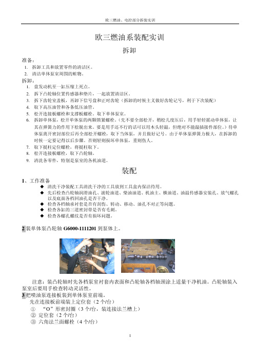
3.4.4改进后的泵室加装了两个贯穿螺钉
l 相对低的油耗
2007-11
26
3.5主燃油系统及油路走向
喷油器 回到油箱
燃油 分配器
燃油调压阀出口 燃油进口
出油箱
燃油泄漏回油
油水分离器 和手油泵 单体泵总成 燃油滤清器
燃油输油泵
2007-11
27
3.5.1燃油低压油路
l考虑:足够的压力防穴蚀,足够的流量冷却 l进油压力:3~6bar,输油泵流量:7~9L/min
一、主要技术结构参数 1.型号: 2.代号: 3.型式: 4.缸数−缸径×行程(mm): 5.进气方式: 6.供油系统: 7.气缸排量L: 二、主要技术性能指标 YC6L280-30 L3800 YC6L310-30 L3600 立式、直列、水冷、四冲程 6-113×140 增压中冷 Delphi电控单体泵 8.424 YC6L330-30 L3700
Delphi单体泵培训拆装手册
电阻值 K 油门开度 信 号 电 压允 许 误 差 范
mV
围
1 A---B 1.6
0%
390
±5%
2 A---B 2.8
100% 3284
±5%
3 A---B 2.9
130% 3845
±5%
4 B---C 1.1
±5%
5 D---F ∞
0%
200
6 D---F 1.18
100% 5000
±5%
测量接口
燃料 箱
燃油滤清 手油泵
燃油分 配器
燃油泄露
输油泵
燃油 滤清
单体泵
喷油 器
燃压
燃料系统的排空方法。
1.先松开油水分离器上面的放气螺栓,用手油泵泵油,泵到没有空气为好,上紧放气螺栓.
2.松开柴油细滤器的出油管螺栓, 用手油泵泵油,泵到没有空气为好,上紧出油管螺栓 3.松开泵室上面的放气螺栓, 用手油泵泵油,泵到没有空气为好,上紧放气螺栓. 4.松开高压油管, 用手油泵泵油,泵到没有空气为好,上紧高压油管螺栓.(注意不要使用马达来拖动发动机排 空)
5
欧三燃油、电控部分拆装实训
a) 把发动机盘车到第一缸压缩上止点。 b) 面对信号盘前端,将信号盘上¢8 的通孔与单体泵泵齿轮上的定位销孔对齐,然后观察正
时信号盘端面上的刻度线是否位于正时齿轮壳上传感器安装孔的中心线上,要求刻线与传 感器安装孔的中心线偏差在±1.5°。 c) 校对正时信号盘的装配是否正确,即把发动机盘到第一缸活塞压缩上止点时,油泵凸轮轴 键槽与垂直方向夹角为 15°,正时信号盘端面上的刻度线是否位于正时齿轮壳上传感器 安装孔的中心线上。 13 装机油进油管组件。 14. 装回油管组件。 15. 装好喷油器(喷油器为专用喷油器,随外表和其他的相似,但绝对不能混用 16. 装高压油管、以及泵室其他的油管 燃油管路走向和连接方式:
Save-T 3 自动盖系统和 Autosave Spa 盖安装指南说明书

This is a general guide on factors to consider for the installationof a Save-T 3 automatic cover system or Autosave spa cover.Detailed installation instructions are available.General Informationfor Installing an Automatic Pool Cover(Save-T ®3 or Autosave™ Spa Cover)Cover-Pools Incorporated 66 East 3335 SouthSalt Lake City, UT 84115800.447.2838801.484.2724©2015 Cover-Pools IncorporatedCover-Pools Incorporated is a wholly owned subsidiary of Zodiac Pool Systems, Inc. ZODIAC® is a registered trademark of Zodiac International, S.A.S.U., used under license.All other trademarks used herein are the property of their respective owners.®WARNING 11ptWARNING12ptWARNING14 ptWARNING27ptWARNING37NOTES 2Table of ContentsTRACK OPTIONS (4)EXCAVATION AND PLUMBING (6)Recessed Mechanism—Underside™ Track or Track Channel (6)Recessed Mechanism—Universal, SnapTop™, or Flush Track (7)ELECTRICAL (8)Keyed Motor Control (Standard Equipment) (8)Hydraulic Power System (8)Auto-Shutoff with Amp Limiter and Accessory Board (9)Auto-Shutoff with Amp Limiter/Accessory Board/Wireless (9)MECHANISM HOUSING (10)Recessed Concrete, Wood, or UPB Box—Underside™ Track (10)Recessed Concrete, Wood, or UPB Box—AutosaveOPTION 1: Conduit comes from back of box (11)Recessed Concrete, Wood, or UPB Box—AutosaveOPTION 2: Conduit comes from side of box. (12)Recessed Concrete, Wood, or UPB Box—Universal or SnapTop™ Track (13)Recessed Wood Box Construction (13)Deck-Mounted Bench Construction (13)COPING AND DECK (14)Gunite Layout—Underside™ track (14)Coping or Deck Requirements—Underside track (14)Coping or Deck Requirements—Underside track (cont.) (15)Tile Beam—Underside track (15)RECESSED BOX COVER (16)Brackets (16)Vanishing Lid™ System (16)Bezel™ lids (16)SPECIFICATIONS (17)COVER SIZING AND PRICING (18)Cost Considerations (19)31Vinyl-Liner PoolTrack Channel• Track channel allows for custom cantilever profilesVinyl-Liner Pool Coping Undertrack System • For vinyl-liner pools • 90°, 45°, 6" and 24"corners available• Tracks locked in placeby shims• Standard or bullnose coping optionsStandard2Flush Track - NEW• For new or existing pools • Installed flush with deck • Vinyl-liner, fiberglass or concrete pools• Anodized aluminum2-13/16"11/16"Recommended for Indoor use onlySpecial Construction Applicationsfrom waterline AB=CDAD=CBE F G Track squared to box or mechanismGE = 6'GF = 8'FE = 10'345Hydraulic Power System(Optional)3" poly or PVC pipe from housing to power unit.NO SHARP BENDS!hydraulic motormust be followed. Refer to the prewiring instructions for detailed instructions and additional mounting options.CONDUIT FOR HYDRAULIC HOSEWITH SWEEPING BENDSAll switches/control pads must be mounted in full view of the cover operation.Hydraulic motors must bemounted above ground level.Option 1: Auto-shutoff mounted outside housing.Auto-Shutoff with Accessory Board/ AquaLink® and Wireless67Box Side View—Underside TrackUnderside TrackBox Dimensions for Save-T ® 3MOTOR MOPPOSITEOBEAM BTHROATTDEPTH DWIDTH WPools under55 ft. long x 24 ft. wide 32"10"8-12"2" min to finished beam 12-1/2" min 12-1/2" min UPB BOX Pools up to 55 ft. long32"10"8-12"2" min to finished beam 13"13"Pools over55 ft. long x 24 ft. wide32"10"8-12"2" min to finished beam14½"14½"Pools over 65 ft. long or 25 ft. wide and vanishing-edge pools — Call Cover-Pools 1-800-447-2838Consult a certified electrician and the pre-wiring diagrams for conduit and bonding requirements.OPTION 1: Conduit comes from back of box.8OPTION 2: Conduit comes from side of box.10Deck-Mounted Fiberglass EndsThree-piece adjustable steelbrackets provide a maximum height of 20" by 24" wide. Surface material is not included.Fiberglass ends are an economical andpractical solution to cover the deck-mounted mechanism. Available in white.roller tubeRecessed Wood Box ConstructionRequirements:The material used to construct the box should be:2" x 12" pressure-treated lumber or redwood Upper trim:2" x 4" pressure-treated lumber or redwoodAlso available with stainless-steel base.to Everlast ™ Bench Kitsystem.Deck Mount TrackBox Dimensions for Save-T ® 3MOTOR MOPPOSITEOBEAM BTHROATTDEPTH DWIDTH WPools under 55 ft. long x 24 ft. wide 32"10"8-12"2" min to finished beam 12½" min 12½" min UPB BOX Pools up to 55 ft. long 32"10"8-12"2" min to finished beam 13"13"Pools over 55 ft. long x 24 ft. wide32"10"8-12"2" min to finished beam14½"14½"Pools over 65 ft. long or 25 ft. wide and vanishing-edge pools — Call Cover-Pools 1-800-447-2838Consult a certified electrician and thepre-wiring diagrams for conduit and bonding requirements.11Coping or Deck Requirements—Underside track• All corners of the coping must be square • Minimum 2" cantilever from tile on side walls• Minimum 3" cantilever from tile on end wall opposite the mechanismAt the recessed box end, the pool wall (bond beam) must be shot 2½" (2" finished with tile) lower than the side walls.The top inside pool corners (above the waterline) must be square, not radius.Any interior wall, such as for spas, also must be gunited 2½" (2" finished with tile) lower than the side walls.form2½" lowerside wallcover boxbond beamtop of side wall2½" lower than side wallCOPING AND DECKside wallinterior wallform12The lowered pool wall is finished with a tile surface.For the lowered wall edge, use a rounded tile on the front and back edges to minimize scraping on the cover.Opening 2" finished with tile or other material1/4" round edge13Note: The deck thickness must beincreased for extended trays if the leading edge is going to fit under the tray. Contact Cover-Pools for more information.The maximum width of any tray is 24".The maximum length of tray is 24".Walk-On Vanishing LidThis design offers an adjustable tray support system for any type of deck material. Stainless-steel or aluminum trays and stainless-steel brackets provide the support base for a strong walk-on lid that can blend with the surrounding deck.behind the box for anchoring brackets.Quad-core™ Fabric• Material: PVC vinyl, laminated over a reinforcedpolyester mesh for strength and tear resistance• Rigorously Tested: The exclusive formula is theproduct of 50 years of testing and experience• Designed for the Pool Environment: UV, mildew,and pool-chemical resistant with superiordimensional stability• Weight: 18 oz. per square yard• Thickness: 28 mil laminated vinyl• Strength: Exceeds the ASTM F1346-91 minimumstandard of 485 lbs. per 4' radius• Construction: Fabric is attached to webbing andlow-stretch rope (70,000+ cyclic loading fatigue life)with double-sewn Dabond® bonded polyester thread for durability• 11 standard colors: dusky blue, royal blue, light blue,aqua, forest green, beige, tan, brown, gray, slate gray, and black• Additional special-order colors available• 7- year limited prorated standard warranty• Sewn webbing in 9 optional colors• Optional Ultimate™ heat sealed webbing in 6 colors • Optional Ultimate™ rope (100,000+ cyclic loadingfatigue life) or Stainless steel cableTrack Styles• 7-year limited warranty on all aluminum extrusions• All aluminum extrusions are 100% anodized• Underside™, SnapTop™, Universal, Slim™, or Flushtrack• Safety-Lock track channel• Top-mounted track channel for concrete andfiberglass pools• Inverted track channel for concrete ordeck-on-deck applications• Track channel system for vinyl pools• Coping channel for vinyl pools• V-Pak™ kit for vinyl pools (includes system, fabric,channel, box, and lid)• Reusable coping forms (3 Profiles)• 45-degree vanishing-edge pools• 90-degree vanishing-edge pools• NEW Corr-Resist™ non-metallic Track Channel Mechanism• Exclusive Corr-Resist end hubs with stainless steel,designed for salt water systems• Marine-grade anodized aluminum frame and bracket • Limited lifetime warranty• Exclusive positive-shift system• Exclusive Corr-Resist rope reel with stainless steel side plates designed for quiet operation• Standard electric system comes with either the slipclutch or auto-shutoff Mechanism Housing• Standard 12" aluminum lid with either 4" or 6" hinge • Bezel™ lids, 16" and 18" wide• Vanishing Lid™ trays, 12"–24" wide with stainless-steel trays and stainless-steel adjustable brackets• Fiberglass deck-mounted mechanism end housings • Ultimate™ Polymer recessed box• Everlast™ modular bench kit (available in 4 colors)• Bench frame assemblyPower and Controls• 3-year limited warranty on all electrical• 3/4 hp waterproof electric motorOptional Ultimate™ High-Torque Motor• 1 ½ hp/2000 PSI hydraulic system• Safety lockout key control• CoverLink™ touchpad control (wired or wireless)• Low-voltage auto-shutoff with key switch• Water-feature shutoff• Jandy iAquaLink™ InterfaceSafety• Exceeds ASTM F1346-91 requirements• Full UL listing• Bonding included with all automatic systems• Automatic water-removal cover pump included• NOTE:Some cover manufacturers treat cover pumps andbonding as options for their systems. A solid safetycover without a pump is NOT approved to ASTMF1346-91 safety standards. The installation of anautomatic cover system without bonding is not aUL-listed product.Other Options• Painting—all extrusions can be painted to match mostdeck surfaces or fabric colors14TRACK SPACE x POOL LENGTH=COVER SQUARE-FOOT PRICINGTrack widths over 25' or lengths over 65' require factory approval (maximum track space is 36'). 15Cost ConsiderationsExcavation/Plumbingq Housing excavationq3" drain for housing drain— drain to airor drain to pitq3" conduit for hydraulic-unit housingElectricalq1/2" Conduit for mechanism powerq Electric run to key switchq15-amp GFCI dedicated circuit for mechanism at panel (20 AMP for hydraulic)q Electric runs over 50' require heavy-gauge wireq Electrical run for accessory boardq1/2" Conduit (for low voltage wires) required with Auto-shutoff/CoverLink wired controlsConcreteq Concrete, gunite or shotcrete box, minimum 6" thick, 3500 PSI, (no rebound)q Additional deck around housing/mechanismq Tile on lower beam, beam cover or otherCover/Mechanismq Unit price based on track space x pool length including steps, plus optionsq Track space 25' 6" or more may require a larger main mechanism tube and larger leading edgefor fabric TrackUnderside™ track or Universal track standardq Track channel for concrete or fiberglass pools(2 or 3 sided)q Flush trackq SnapTop™ trackq Vinyl-liner pool coping 90°, 45°, 6" radius or 24"radiusq Track channel for vinyl-liner poolsq Vanishing edge 45° or 90°q Painted track extrusionsHousingAluminum lid, bench frame or fiberglass ends standardq Painted lid extrusionsq Aluminum Lids: Standard, Bezel™ lids, or Flush Mount q Walk-on Vanishing Lid™ traysq Bench for deck-mounted mechanismPower/Controls110 V motor and hard-wired 3-wire key standardq Auto-shutoff control with amp limitq Wireless CoverLink™ digital touchpad controlq Wired CoverLink digital touchpad controlq Water-feature shutoff/accessory boardq Hydraulic pump with hydraulic hosesq Jandy iAquaLink™ interface & control16SAVE-T ® 3 “BIG RED”SLIP CLUTCH·construction · long-wearing industrial-grade friction material (not plastic)· waterproof and temperature-proof operation · no replacement parts needed · lifetime warranty AquaLink ® interface Board · cover status controls pool features · view if cover is open/closed · reduce the filter pump time · adjust AquaPure output · and booster pump cleaners when the pool is covered. · connect to an iPhone with the iAuquaLink™· stainless steel and Corr-Resist™ components · designed for mineral sanitizing systems · minimizes salt corrosion · can be retrofitted to previous modelsEXCLUSIVE!MARINE-GRADE ANODIZED ROLLER DRUM· strong 17 gauge thick aluminum tube · 6" & 8" diameters available · anodized aluminum protects against corrosion and oxidation· · · NEW GLIDER STOP · prevents glider from running past the track · ensures cover stops in · 3/4 hp WATERPROOF MOTOR·3/4 hp, 41 rpm, 1600 in-lbs of torque · capacitor-start, capacitor-run · O-ring sealed and potted wire-entry points ·stainless-steel gears with sealed permanent grease · UL Listed ·Optional Ultimate™ High-1375 in-lbs of torqueCOVERLINK™ CONTROL· 10-number wireless or wired touch pad · wireless systems use secure FM-radio technology with signal lock · fits in a single gang box · uses AA batteriesWEBBING STOP BLOCK· simple installation to set cover travel length · clamp design allows KEY SWITCH· 3-wire key switch for simple wiring · mounts in standard switch box · NEW brushed stainless steel faceplate (high-voltage only)QUAD-CORE™ 18ozFABRIC COLORS · dusky blue · royal blue · light blue · aqua · forest green · beige · tan · brown · gray · slate gray · black · Optional colored webbing or Heat Sealed Webbingsystem for simple cover alignment · choose between ratcheting or locked rope reels · easy adjustment on out-of-square pools · simple adjustment of cover alignment · simple change-over to locked or unlocked reels · can be retrofitted to previous modelsAUTO-SHUTOFF WITH AMP LIMITER· compact potted waterproof design · adjustable amp limiter overload safety circuit · LED indicator and diagnostic lights · optional water-feature control board (can control 12- and 24-volt motorized valves or pump motors up to 30 amps)LOW-STRETCH ROPE · 70,000 cycle loading fatigue life · attached with double-sewn, Dabond® bonded polyester thread. ULTIMATE™ ROPE · 100,000 cycle loading fatigue life STAINLESS STEEL CABLE · superior durability in a pool environment · does not stretch or shrink, reducing realignment service calls。
叶片式液压泵 T7CS 系列产品介绍说明书

T7CS, Denison 叶片泵主要技术信息泵理论排量Vi最高转速最高压力HF-0, HF-1HF-2HF-4, HF-5HF-0, HF-2HF-1, HF-4, HF-5系列规格间歇连续间歇连续cm 3/rev.rpmrpmbarbarbarbarT7C SE1758,325001800260230210175E2063,8E2270,3E2579,31500HF-0, HF-2 = 石油基抗磨液压油 HF-1 = 石油基液压油(非抗磨)HF-4 = 水乙二醇液HF-5 = 合成液压油(磷酸脂液等)注:更多的详细资料,或若上列性能参数不能满足您的特殊工况要求,请与当地的派克办事处联系。
主要特征性能稳定T7CS 系列叶片泵是为变速驱动而设计的,并且转速范围很宽。
和我们其他的T7系列叶片泵一样,随着时间的推移,性能仍然很稳定,使得该类叶片泵成为现代电液操作机器的理想解决方案。
寿命长压力平衡概念增加了泵的寿命。
而双唇口叶片增加了抗固体颗粒污染能力。
噪音低Denison 叶片泵技术在泵的整个工作范围和整个生命周期中允许低的噪音水平。
通用性和紧凑性T7CS 系列叶片泵提供了几种排量规格,最大达80 cc/rev,在不改变泵与电机连接的前提下,很好地扩展了T7BS 系列叶片泵的排量规格。
T7CS 系列叶片泵也可以选用SAE 花键轴,允许泵轴直接与电机轴相连接。
T7CS, Denison 叶片泵订货代号及安装尺寸型号T7CS - E25 - 4 R 00 - A 1 MW - MØ48SUCTION Ø25,4PRESSURE PST7CS 系列 - SAE J744SAE B 2孔安装法兰排量容积排量(cm3/rev.)E17 = 58,3E20 = 63,8E22 = 70,3E25 = 79,3传动轴类型1 = 平键轴(SAE B)3 = 花键轴(SAE B) 13齿4 = 花键轴(SAE BB) 15齿转向(从轴端方向看)R = 右转(顺时针)L = 左转(逆时针)修改代码Ex : NOP = 不喷漆油口形式MW = S = 特殊的法兰P = 1" - SAE J518 4螺栓法兰 公制螺纹密封等级1 = S1 BUNA N 5 = S5 VITON®设计序列号油口方向配置00 = 标准配置输入扭矩极限:轴Vi [cm 3/rev] x p max. [bar]Nm 116500262320600327420600327重量:23,0 kg转动惯量:7,5 Kgm 2 x 10⁻⁴P = 压油口S = 吸油口派克汉尼汾在中国的联系方式派克汉尼汾中国总部上海市金桥出口加工区云桥路280号邮编:201206电话:+86 - 21 - 2899 5000北京分公司北京经济技术开发区荣华南路2号院2号楼2201室邮编:100004电话:+86 - 10 - 8527 7300广州分公司广州市萝岗区科学城彩频路11号广东软件科学园F栋202室邮编:510663电话:+86 - 20 - 3212 1688大连办事处大连市高新园区火炬路3号纳米大厦11层1101室邮编:116023电话:+86 - 411 - 3964 6767西安办事处西安市高新区定昆池三路777号邮编:710065电话:+86 - 29 - 8111 8062成都办事处成都市锦江区锦东路568号摩根中心2栋10楼7号邮编:610066电话:+86 - 28 - 6180 6800长沙服务中心长沙市经济技术开发区板仓南路26号新长海数码中心2楼V24-V25室邮编:410005电话:+86 - 731 - 8985 1529派克汉尼汾香港有限公司香港九龙尖沙咀海港城港威大厦2座20楼01 - 04室电话:+86 - 852 - 2428 800819-06-B HYD-CH-4P-T7CSVSD。
沙鹧鸪泵(Sandpiper Pump)G10F型号使用和操作手册说明书
Certified QualityWarren Rupp, Inc.A Unit of IDEX Corporation800 N. Main St.,Mansfield, Ohio 44902 USA Telephone (419) 524.8388Fax (419) © Copyright 2016 Warren Rupp, Inc.All rights reservedModel G10FMetallicDesign Level 1Natural Gas-Operated 1" Flap ValveQuality System ISO 9001 CertifiedEnvironmental Management SystemISO 14001 CertifiedCertified to CSA Technical Letter No, R-14Certified to ANSI LC6-2008SERVICE & OPERATING MANUALOriginal InstructionsU M P S P E C S7: W A R R A N T YRead the safety warnings and instructions in this manual before pump installation and start-up. Failure to comply with the recommendations stated in this manual could damage the pump and void factory warranty.When used for toxic or aggressive fluids, the pump should always be flushed clean prior to disassembly.Airborne particles and loud noise hazards. Wear eye and ear protection.Before maintenance or repair, shut off the compressed air line, bleed the pressure, and disconnect the air line from the pump. Be certain that approved eye protection and protective clothing are worn at all times. Failure to follow these recommendations may result in serious injury or death.ATEX compliant pumps are suitable for use in explosive atmospheres when the equipment is properly grounded in accordance with local electrical codes. Pumps equipped with electrically conductive diaphragms are suitable for the transfer of conductive or non-conductive fluids of any explosion group. When operating pumps equipped with non-conductive diaphragms that exceed the maximum permissible projected area, as defined in EN 13461-1: 2009 section 6.7.5 table 9, the following protection methods must be applied:• Equipment is always used to transfer electrically conductive fluids or• Explosive environment is prevented from entering the internal portions of the pump, i.e. dry running For further guidance on ATEX applications, please consult the factory.When the pump is used for materials that tend to settle out or solidify, the pump should be flushed after each use toprevent damage. In freezing temperatures the pump should be completely drained between uses.Before pump operation, inspect all fasteners for loosening caused by gasket creep. Retighten loose fasteners to prevent leakage. Follow recommended torques stated in this manual.Nonmetallic pumps and plastic components are not UV stabilized. Ultraviolet radiation can damage these parts and negatively affect material properties. Do not expose to UV light for extended periods of time.In the event of diaphragm rupture, pumped material may enter the air end of the pump, and be discharged into the atmosphere. If pumping a product that is hazardous or toxic, the air exhaust must be piped to an appropriate area for safe containment.This pump is pressurized internally with air pressure during operation. Make certain that all fasteners are in good condition and are reinstalled properly during reassembly.Take action to prevent static sparking. Fire or explosion can result, especially when handling flammable liquids. The pump, piping, valves, containers and other miscellaneous equipment must be properly grounded.Safety InformationGrounding ATEX PumpsUse safe practices when liftingTable of ContentsSECTION 1: PUMP SPECIFICATIONS (1)• Explanation of Nomenclature• Performance• Materials• Dimensional DrawingsSECTION 2: INSTALLATION & OPERATION (4)• Principle of Pump Operation• Recommended Installation Guide• Troubleshooting GuideSECTION 3: EXPLODED VIEW (7)• Composite Repair Parts Drawing• Composite Repair Parts List• Material CodesSECTION 4: GAS END (10)• Gas Distribution Valve Assembly• Pilot Valve Assembly• Intermediate AssemblySECTION 5: WET END (12)• Diaphragm Drawing• Diaphragm ServicingSECTION 7: WARRANTY & CERTIFICATES (14)• Warranty• EC Declaration of Conformity - Machinery• EC Declaration of Conformity - ATEX 1 2 3 4 5 6 7Explanation of Pump NomenclatureATEX DetailNon-Wetted Material OptionsA Painted Aluminum with Nitrile Elastomer PartsV Painted Aluminum with FKM Elastomer PartsPorting OptionsN NPT Threads B BSP TaperedPump StyleS StandardMuffler OptionsX No Muffler Permitted *Pump Brand G Gas OperatedPump Size10 1"Check Valve TypeF Flap Design Level1Design LevelWetted MaterialS Painted Stainless Steel A Painted AluminumDiaphragm/Check Valve MaterialsB Nitrile/Nitrile V FKM/FKMCheck Valve SeatS Stainless SteelYour Serial #: (fill in from pump nameplate) _____________________________________Pump PumpCheck Design Wetted Diaphragm/ Check Valve Non-Wetted Porting PumpMuffler Pump BrandSizeValveLevelMaterial Check Valve Seat Material OptionsStyleOptionsOptionsG XX X X X X X X X X X XXModel #: G 20 F__ ____ __ __ __ __ __ __ __ __ __ ____(fill in from pump nameplate)Your Model #:II 2GD T5II 2G c T5II 2D c T100°C1PerformanceG10FSUCTION/DISCHARGE PORT SIZE 1” (25.4mm) NPT1” (25.4mm) BSP TaperedCAPACITY• 0 to 70 gallons per minute (0 to 265 liters per minute)GAS DISTRIBUTION VALVE • No-lube, no-stall design SOLIDS-HANDLING • Up to 1 in. (25mm)HEADS UP TO• 100 psi or 231 ft. of water (7 bar or 70 meters)MAXIMUM OPERATING PRESSURE • 100 psi (7 bar)DISPLACEMENT/STROKE • .10 Gallon / .38 liter SHIPPING WEIGHT • Aluminum 48 lbs. (21kg)• Stainless Steel 79 lbs. (36kg)100755025150125200175225250275300B A R1273456P S ILiters per minute U.S. Gallons per minute CAPACITYH E A DGAS CONSUMPTION MODEL G10F Performance CurvePerformance based on the following: elastomer fitted pump, flooded suction,water at ambient temperature. Average displacement per pump stroke: .10 Gallons (.38 Liters).The use of other materials and varying hydraulic conditions may result in deviations in excess of 5%.MaterialsAmbient temperature range: -20°C to +40°CProcess temperature range: -20°C to +100°C for models rated as category 2 equipmentIn addition, the ambient temperature range and the process temperature range do not exceed the operating temperature range of the applied non-metallic parts as listed in the manuals of the pumps.1: P U M P SG10F Natural Gas Operated 1" Flap ValveDimensions in inches (metric dimensions in brackets). Dimensional Tolerance .125" (3mm).1" BSP TAPEREDPORT ROTATION)Dimensional Drawings1Gas-Operated Double Diaphragm pumps are powered by compressed gas, nitrogen or natural gas.The main directional (gas) control valve ① distributes compressed gas to an gas chamber, exerting uniform pressure over the inner surface of the diaphragm ②. At the same time, the exhausting gas ③ from behind the opposite diaphragmis directed through the gas valve assembly(s) to an exhaust port ④.As inner chamber pressure (P1) exceeds liquid chamber pressure (P2), the rod ⑤ connected diaphragms shift together creating discharge on one side and suction on the opposite side. The discharged and primed liquid’s directions are controlled by the check valves (ball or flap)⑥ orientation. The pump primes as a result of the suction stroke. The suction stroke lowers the chamber pressure (P3) increasing the chamber volume. This results in a pressure differential necessary for atmospheric pressure (P4) to push the fluid through the suction piping and across the suction side check valve and into the outer fluid chamber ⑦.Suction (side) stroking also initiates the reciprocating(shifting, stroking or cycling) action of the pump. The suction diaphragm’s movement is mechanically pulled through its stroke. The diaphragm’s inner plate makes contact with an actuator plunger aligned to shift the pilot signaling valve. Once actuated, the pilot valve sends a pressure signal to the opposite end of the main directional gas valve, redirecting the compressed gas to the opposite inner chamber.Gas LineDischarged FluidDischarge StrokeSuction StrokePrimed FluidPrinciple of Pump OperationPump can be submerged if the pump materials of construction are compatible with the liquid being pumped. The gas exhaust must be piped above the liquid level. When the pumped product source is at a higher level than the pump (flooded suction condition), pipe the exhaust higher than the product source to prevent siphoning spills.2: I N S T A L & O PRecommended Installation GuideInstallation And Start-UpLocate the pump as close to the product being pumped as possible. Keep the suction line length and number of fittings to a minimum. Do not reduce the suction line diameter.Gas SupplyConnect the pump gas inlet to a gas supply with sufficient capacity and pressure to achieve desired performance. A pressure regulating valve should be installed to insure gas supply pressure does not exceed recommended limits.Gas Valve LubricationThe gas distribution system is designed to operate WITHOUT lubrication. This is the standard mode of operation. If lubrication is desired, install a gas line lubricator set to deliver one drop of SAE 10 non-detergent oil for every 20 SCFM (9.4 liters/sec.) of gas the pump consumes. Consult the Performance Curve to determine gas consumption.Gas Line MoistureWater in the compressed gas supply may cause icing or freezing of the exhaust gas, causing the pump to cycle erratically or stop operating. Water in the gas supply can be reduced by using a point-of-use gas dryer.Gas Inlet And PrimingTo start the pump, slightly open the gas shut-off valve. After the pump primes, the gas valve can be opened to increase gas flow as desired. If opening the valveincreases cycling rate, but does not increase the rate of flow, cavitation has occurred. The valve should be closed slightly to obtain the most efficient gas flow to pump flow ratio.Note:after the flexible connectionby pump connections.In the event of a diaphragm rupture, pumped fluid can enter the center section of the pump and exit through the gas exhaust port. When pumping hazardous fluids, it is recommended to pump the exhaust air to a safe location.Available Accessories: 1. Filter/Regulator020.064.000 FilterVENTING WARNING: This filter is equipped with a stainless steel manual drain. The port is 1/8" NPT. When draining moisture from the filter, first shut off the natural gas supply.020.058.000 REGULATOR WITH GAGEPRESSURE WARNING: This regulator is to be installed at point of use with the pump. The maximum gas supply is 400psi. Full line pressure needs to be regulated below 400psi prior to the regulator installation position.VENTING WARNING: This regulator is equipped with a 1/4" NPT vent port. In the event of a diaphragm rupture, natural gas can be exhausted into the surrounding environment. Connect a conductive hose orpipe to the vent port to send the escaping natural gas to a safe area for gas reclamation. Make sure to ground the regulator, hose, and/or pipe.2Troubleshooting Guide*******************************************************************************************************2 : I N S T A L & O PComposite Repair Parts Drawing476.361.363 Gas End Kit with FKM elastomer partsSleeve and Spool Set, Pilot Valve Assembly, Bumpers, Bushings, Gaskets, O-rings, Seals, Plungers, and Retaining Rings476.341.363 Gas End Wear Kit with FKM elastomer parts Bumpers, Bushings, Gaskets, O-rings, Seals, Plungers, and Retaining Rings476.361.000 Gas End KitSleeve and Spool Set, Pilot Valve Body Assembly,Bumpers, Bushings, Gaskets, O-rings, Seals,Plungers, and Retaining Rings476.341.000 Gas End Wear Kit(With new die cast aluminum air valve body) Bumpers, Bushings, Gaskets, O-rings, Seals, Plungers, and Retaining Rings 476.286.360 Wet End KitNitrile Diaphragms, Nitrile Flap Valves, Nitrile Hinge and Wear Pads, Nitrile O-rings and Seals 476.286.363 Wet End KitFKM Diaphragms, FKM Flap Valves, FKM Hinge and Wear Pads, FKM O-rings and Seals3Composite Repair Parts ListItem Part Number Description Qty 1 031.203.000 Assembly, Air Valve 1031.203.363 Assembly, Air Valve with FKM O-rings 12 070.012.571 Bearing, Sleeve 23 095.074.558 Pilot Valve Assembly 1095.074.363 Pilot Valve Assembly 14 114.007.157 Bracket, Intermediate 15 115.071.330 Bracket, Mounting 16 132.019.360 Bumper 2132.019.363 Bumper 2 7 132.022.360 Bumper, Actuator 2132.022.363 Bumper, Actuator 28 135.034.506 Bushing, Plunger 29 165.134.157 Cap, Air Inlet, Ass'y 110 170.029.330 Capscrew, Hex HD 2411 170.033.330 Capscrew, Hex HD 4170.083.330 Capscrew, Hex HD 412 170.045.330 Capscrew, Hex HD 1213 170.063.330 Capscrew, Hex HD 114 170.080.330 Capscrew, Hex HD 415 170.043.330 Capscrew, Hex HD (AL Center) 616 196.042.157 Chamber, Inner (AL Center) 117 196.043.157 Chamber, Inner (AL Center) 118 196.199.156 Chamber, Outer 2196.199.110 Chamber, Outer 219 920.025.000 Grounding Cable 120 286.008.360 Diaphragm 2286.008.363 Diaphragm 2 21 312.119.156 Elbow, Suction 2312.119.110 Elbow, Suction 2 22 312.120.156 Elbow, Discharge 2312.120.110 Elbow, Discharge 2 23 338.014.360 Flap Valve 4338.014.363 Flap Valve 424 350.002.360 Foot, Rubber 425 360.056.379 Gasket 126 360.057.360 Gasket 127 360.058.360 Gasket 128 518.205.156 Manifold 2518.205.156 E Manifold 2518.205.110 Manifold 2518.205.110 E Manifold 2Item Part Number Description Qty30 542.001.330 Nut, Square 131 545.004.330 Nut, Hex, 5/16-18 1432 547.002.110 Nut, Stop 1233 560.001.360 O-Ring 2560.001.363 O-Ring 234 560.038.360 O-Ring 8560.038.363 O-Ring 835 560.040.360 O-Ring 2560.040.363 O-Ring 236 560.198.360 O-Ring 4560.198.363 O-Ring 437 570.018.360 Pad, Hinge 4570.018.363 Pad, Hinge 438 570.019.360 Pad, Wear 2570.019.363 Pad, Wear 239 612.022.330 Plate, Diaphragm, Inner 240 612.108.157 Assembly, Diaphragm Plate 2612.101.110 Assembly, Diaphragm Plate 241 618.003.330 Plug, Pipe, 1/4 342 620.007.114 Plunger, Actuator 243 670.053.110 Retainer 444 675.040.360 Ring, Sealing 2675.040.363 Ring, Sealing 245 675.042.115 Ring, Retaining 246 675.065.360 Ring, Sealing 4675.065.363 Ring, Sealing 447 685.039.120 Rod, Diaphragm 148 706.013.330 Screw, Machine 449 720.010.375 Seal, U-Cup 2720.010.363 Seal, U-Cup 250 720.066.360 Seal, Seat 4720.066.363 Seal, Seat 451 722.101.110 Seat, Flap 452 807.018.110 Stud, 1/4-20 853 900.004.330 Washer, Lock, 5/16 3254 901.005.330 Washer, Flat, 3/8 455 901.012.180 Washer, Sealing 256 901.005.330 Washer, Flat 3/8 6901.035.330 Washer, Flat 1/4 657 901.035.330 Washer, Flat 1/4 1LEGEND:= Items contained within Air End Kits= Items contianed within Wet End KitsNote: Kits contain components specific to the material codes.3Material Codes - The Last 3 Digits of Part Number000.....Assembly, sub-assembly;and some purchased items 010.....Cast Iron015.....Ductile Iron020.....Ferritic Malleable Iron 080.....Carbon Steel, AISI B-1112 110.....Alloy Type 316 Stainless Steel 111 .....Alloy Type 316 Stainless Steel(Electro Polished) 112.....Alloy C113.....Alloy Type 316 Stainless Steel(Hand Polished) 114.....303 Stainless Steel 115.....302/304 Stainless Steel 117.....440-C Stainless Steel (Martensitic) 120.....416 Stainless Steel(Wrought Martensitic) 148.....Hardcoat Anodized Aluminum 150.....6061-T6 Aluminum 152.....2024-T4 Aluminum (2023-T351) 155.....356-T6 Aluminum 156.....356-T6 Aluminum 157.....Die Cast Aluminum Alloy #380 158.....Aluminum Alloy SR-319 162.....Brass, Yellow, Screw Machine Stock 165.....Cast Bronze, 85-5-5-5 166.....Bronze, SAE 660 170.....Bronze, Bearing Type,Oil Impregnated 180.....Copper Alloy305.....Carbon Steel, Black Epoxy Coated 306.....Carbon Steel, Black PTFE Coated 307.....Aluminum, Black Epoxy Coated 308.....Stainless Steel, Black PTFE Coated 309.....Aluminum, Black PTFE Coated 313.....Aluminum, White Epoxy Coated 330.....Zinc Plated Steel 332.....Aluminum, Electroless Nickel Plated 333.....Carbon Steel, ElectrolessNickel Plated 335.....Galvanized Steel 337.....Silver Plated Steel 351.....Food Grade Santoprene®353.....Geolast; Color: Black 354.....Injection Molded #203-40Santoprene® Duro 40D +/-5;Color: RED356.....Hytrel®357.....Injection Molded Polyurethane 358.....Urethane Rubber(Some Applications)(Compression Mold) 359.....Urethane Rubber 360.....Nitrile Rubber Color coded: RED 363.....FKM (Fluorocarbon)Color coded: YELLOW 364.....EPDM RubberColor coded: BLUE365.....Neoprene RubberColor coded: GREEN366.....Food Grade Nitrile368.....Food Grade EPDM371.....Philthane (Tuftane)374.....Carboxylated Nitrile375.....Fluorinated Nitrile378.....High Density Polypropylene379.....Conductive Nitrile408.....Cork and Neoprenepressed Fibre426.....Blue Gard440.....Vegetable Fibre500.....Delrin® 500502.....Conductive Acetal, ESD-800503.....Conductive Acetal, Glass-Filled506.....Delrin® 150520.....Injection Molded PVDFNatural color540.....Nylon542.....Nylon544.....Nylon Injection Molded550.....Polyethylene551.....Glass Filled Polypropylene552.....Unfilled Polypropylene555.....Polyvinyl Chloride556.....Black Vinyl557.....Conductive Polypropylene558.....Conductive HDPE570.....Rulon II®580.....Ryton®600.....PTFE (virgin material)Tetrafluorocarbon (TFE)603.....Blue Gylon®604.....PTFE606.....PTFE607.....Envelon608.....Conductive PTFE610.....PTFE Encapsulated Silicon611.....PTFE Encapsulated FKM632.....Neoprene/Hytrel®633.....FKM/PTFE634.....EPDM/PTFE635.....Neoprene/PTFE637.....PTFE, FKM/PTFE638.....PTFE, Hytrel®/PTFE639.....Nitrile/TFE643.....Santoprene®/EPDM644.....Santoprene®/PTFE656.....Santoprene® Diaphragm andCheck Balls/EPDM Seats661.....EPDM/Santoprene®666.....FDA Nitrile Diaphragm,PTFE Overlay, Balls, and Seals668.....PTFE, FDA Santoprene®/PTFE• Delrin and Hytrel are registeredtradenames of E.I. DuPont.• Nylatron is a registered tradenameof Polymer Corp.• Gylon is a registered tradenameof Garlock, Inc.• Santoprene is a registered tradenameof Exxon Mobil Corp.• Rulon II is a registered tradenameof Dixion Industries Corp.• Ryton is a registered tradenameof Phillips Chemical Co.• Valox is a registered tradenameof General Electric Co.R E C YC L I N GMany components of SANDPIPER® GODDpumps are made of recyclable materials.We encourage pump users to recycle wornout parts and pumps whenever possible,after any hazardous pumped fluids arethoroughly flushed.3Air Distribution Valve Assembly With Aluminum CenterStep 1:Step 5:Step 6:Note:= Items contained within Gas End Kits= Items contianed within Wet End KitsNote: Kits contain components specific to the material codes.Qty1112288Qty11122884:GASENDPilot Valve AssemblyPILOT VALVE ASSEMBLY PARTS LIST WITH NITRILE O-RINGSItem Part Number DescriptionQty 4 095.074.558 Pilot Valve Assembly 14A 095.071.558 Pilot Valve Body 14B 755.025.148 Pilot Valve sleeve 14C 560.033.360 O-Ring 44D 775.014.115 Pilot Valve Spool 14E 560.023.360 O-Ring 44F675.037.080Retaining Ring1Pilot Valve ServicingWith Pilot Valve removed from pump.Step 1: Remove snap ring (4F).Step 2: Remove sleeve (4B), inspect O-Rings (4C), replace if required.Step 3: Remove spool (4D) from sleeve (4B),inspect O-Rings (4E), replace if required.Step 4: Lightly lubricate O-Rings (4C) and (4E). Reassemble in reverse order.LEGEND:= Items contained within Gas End Kits = Items contianed within Wet End KitsNote: Kits contain components specific to the material codes.PILOT VALVE ASSEMBLY PARTS LIST WITH FKM O-RINGSItem Part Number DescriptionQty 4 095.074.363 Pilot Valve Assembly 14A 095.071.558 Pilot Valve Body 14B 755.025.363 Pilot Valve Sleeve 14C 560.033.363 O-ring 44D 775.014.363 Pilot Valve Spool 1 4E 560.023.363 O-ring 44F675.037.080Retaining Ring14Diaphragm Service DrawingStep 1: With manifolds and outer chambers removed, remove diaphragm assemblies from diaphragm rod. DO NOT use a pipe wrench or similar tool to remove assembly from rod. Flaws in the rod surface may damage bearings and seal. Soft jaws in a vise are recommended to prevent diaphragm rod damage.Step 1.A: NOTE: Not all inner diaphragm plates are threaded. Some models utilize a through hole in the inner diaphragm plate. If required to separate diaphragm assembly, place assembly in a vise, gripping on the exterior cast diameter of the inner plate. Turn the outer plate clockwise to separate the assembly.Always inspect diaphragms for wear cracks or chemical attack. Inspect inner and outer plates for deformities, rust scale and wear. Inspect intermediate bearings for elongation and wear. Inspect diaphragm rod for wear or marks.Clean or repair if appropriate. Replace as required. Step 2:Reassembly: There are two different types of diaphragm plate assemblies utilized throughout the Sandpiper product line: Outer plate with a threaded stud, diaphragm, and a threaded inner plate. Outer plate with a threaded stud, diaphragm, and an inner plate with through hole. Secure threaded inner plate in a vise. Ensure that the plates are being installed with the outer radius against the diaphragm. Step 3: Lightly lubricate, with a compatible material, the inner faces of both outer and inner diaphragm plates when using on non Overlay diaphragms (For EPDM water is recommended). No lubrication is required. Step 4: Push the threaded outer diaphragm plate through the center hole of the diaphragm. Note: Most diaphragms are installed with the natural bulge out towards the fluid side. S05, S07, and S10 non–metallic units are installed with the natural bulge in towards the air side.Diaphragm ServicingStep 5: Thread or place, outer plate stud intothe inner plate. For threaded inner plates, use atorque wrench to tighten the assembly together.Torque values are called out on the exploded view.Repeat procedure for second side assembly. Allow a minimum of 15 minutes to elapse after torquing, then re-torque the assembly to compensate for stress relaxation in the clamped assembly. Step 6: Thread one assembly onto the diaphragmrod with sealing washer (when used) and bumper. Step 7: Install diaphragm rod assembly into pump and secure by installing the outer chamber in place and tightening the capscrews. Step 8: On opposite side of pump, thread the remaining assembly onto the diaphragm rod. Using a torque wrench, tighten the assembly to the diaphragm rod. Align diaphragm through bolt holes, always going forward past the recommended torque. Torque values are called out on the exploded view. NEVER reverse to align holes, if alignment cannot be achieved without damage to diaphragm, loosen complete assemblies, rotate diaphragm and reassemble as described above. 5 : W E T E N DDeclaration of ConformitySignature of authorized person Date of issue Printed name of authorized personRevision Level: FTitleDavid RoseberryEngineering Manager October 20, 2005Date of revisionAugust 23, 2012Manufacturer: Warren Rupp, Inc., 800 N. Main StreetMansfield, Ohio, 44902 USACertifies that Air-Operated Double Diaphragm Pump Series: HDB, HDF, M Non-Metallic, S Non-Metallic, M Metallic, S Metallic, T Series, G Series, U Series, EH and SH High Pressure,RS Series, W Series, SMA and SPA Submersibles, and Tranquilizer ® Surge Suppressors comply withthe European Community Directive 2006/42/EC on Machinery, according to Annex VIII. This product has used Harmonized Standard EN809:1998+A1:2009, Pumps and Pump Unitsfor Liquids - Common Safety Requirements, to verify conformance.5 - YEAR Limited Product WarrantyWarren Rupp, Inc. (“Warren Rupp”) warrants to the original end-use purchaser that no product sold by Warren Rupp that bears a Warren Rupp brand shall fail under normal use and service due to a defect in material or workmanship within five years from the date of shipment from Warren Rupp’s factory. Warren Rupp brands include Warren Rupp ®,SANDPIPER ®, MARATHON ®, PortaPump ®, SludgeMaster™ and Tranquilizer ®.~ See /content/warranty-certifications for complete warranty,including terms and conditions, limitations and exclusions. ~5David Roseberry, Director of Engineering。
电控柴油机故障诊断仪(Delphi单体泵系统)使用说明书
目录1 软硬件清单及USBCAN驱动安装 (1)1.1 硬件清单 (1)1.2 软件清单 (1)1.3 建议机器配置 (1)1.4 USBCAN驱动程序的安装 (1)1.5 诊断仪的安装 (4)2 诊断仪使用说明(适用于3.0 版本) (7)2.1 简述 (7)2.2 硬件连接方法 (7)2.3 软件使用方法 (9)2.3.1 软件进入与初始界面 (9)2.3.2 主界面 (10)2.3.3 故障码显示区 (10)2.3.4状态检测显示 (11)2.3.5 用户脉谱 (15)2.3.6 曲线图显示 (18)2.3.7烧写标定数据 (18)2.3.8自动写脉谱的步骤 (20)2.3.9 修改标定数据 (21)3 注意事项 (22)电控柴油机故障诊断仪使用说明书1 软硬件清单及USBCAN驱动安装1.1 硬件清单一个USBCAN适配器一条USB电缆线一条CAN电缆线1.2 软件清单电控柴油机故障诊断仪用户手册。
诊断工具软件及USBCAN驱动光盘。
1.3 建议机器配置内存256MB。
操作系统WINXP。
1.4 USBCAN驱动程序的安装将USBCAN-I智能CAN接口卡使用USB电缆与PC机正确连接,Windows将检测到新硬件,自动启动“发现新硬件”程序,如图1:12在你希望向导做什么?选择第二个单选项“从列表或指定位置安装(高级)”,单击下一步,便出现图2的选择界面。
图1 检测到新硬件图2 选择搜索和安装选项选择选项“在搜索中包括这个位置”,把位置制定到光盘的“\Usbcan驱动\XP 驱动”目录,单击“下一步”,开始安装,出现图3的显示画面,点击“仍然继续”完成安装。
图3 选择驱动程序34安装后,显示图4,表示安装完成。
1.5 诊断仪的安装进入光盘的“诊断工具软件”目录,点击“setup.exe ”文件开始安装,进入图5的界面,点击“下一步”。
图4 完成新硬件向导5图5 诊断仪安装1图6 诊断仪安装26进入如图6所示的界面,此时如想改变安装目录,则点击“浏览”按钮,选择目标目录,选择好以后,点击“下一步”,进入图7的界面。
EATON XTJP XTJY 泵控制器维护和操作手册说明书
EATON XTJP / XTJY Jockey Pump ControllersDescription1.INSTALLATION AND MOUNTING OF THE CONTROLLER (3)2.SYSTEM PRESSURE CONNECTIONS (3)3.ELECTRICAL CONNECTIONS (3)3.1ELECTRICAL CHECKOUT INSTRUCTIONS (4)3.1.1 Motor Rotation Check (4)3.1.2 Starting and Stopping (4)3.1.3 Motor Circuit Protector / Overload Relay Trip Setting (4)3.1.4 Circuit Breaker Trip Settings (4)3.1.5 Run Period Timer (Optional) (4)FIGURE 1: ELECTRICAL WIRING SCHEMATIC - Three Phase (5)FIGURE 2: DIMENSIONAL DRAWING - NEMA 2 (6)FIGURE 3: ELECTRICAL WIRING SCHEMATIC - WYE DELTA (Star-Delta) (7)FIGURE 4: DIMENSIONAL DRAWING - WYE DELTA (Star-Delta) (8)4.DIGITAL DISPLAY (9)4.1PROGRAMMING...........................................................................................................9, 10, 11INSTALLATION & MAINTENANCE MANUAL FOR JOCKEY PUMP CONTROLLERSIn order to familiarize yourself with the Jockey Pump Controller, please read the instruction manual thoroughly and carefully. Retain the manual for future reference.1. Installation and Mounting of the Controller Carefully unpack the controller and inspect thoroughly.It is recommended that the controller is located as close as is practical to the motor it controlsThe controller is not free standing and must be bolted securely to a wall. For dimensional and weight data please refer to the respective data sheets for the Jockey Pump Controller.2. System Pressure ConnectionThe Jockey Pump Controller is equipped with a Pressure Transducer. The controller is provided with a ¼” NPT female system pressure connection located on the bottom, external side of the enclosure. The connection should be installed as per NFPA, pamphlet No. 20.NOTE: Water lines to the pressure transducer must be free from dirt and contamination.The pressure should not exceed what the pressure transducer is rated for.3. Electrical ConnectionsAll electrical connections should meet nationaland local electrical codes and standards.The controller should be located or so protected that they will not be damaged by water escaping from pumps or pump connections. Current carrying parts of controllers shall be a minimum of 12 inches (305 mm) above the floor level.Prior to starting verify all data on the nameplate such as, catalog number, AC line voltage and horsepower.Inspect all electrical connections, components and wiring for any visible damage and correct as necessary. Ensure that all electrical connections are tightened before energization.Install necessary conduit using proper methods and tools.Incoming AC line voltage is clearly marked L1, L2, L3 and ground, located at the top of the breaker.3.1 Electrical Checkout InstructionsWARNING :The following procedures should be carried out by a qualified electrician familiar with the electrical safety procedures associated with this product and its associated equipment..3.1.1Motor Rotation Check: With the controller energized, move the H.O.A. selector switch to "HAND" then back to “OFF” immediately to check the direction of the motor and pump rotation. If rotation direction is not correct, open the breaker and reverse the phase sequence of the load terminals of the contactor T1, T2, T3 or at the motor terminals.3.1.2Starting and Stopping: Energize the controller. With the H.O.A. selector switch set to “AUTO”, if the system water pressure is lower than the pressure transducer set-point pressure (1Lo), the pump will start. The pump will stop when pressure is above the stop point (1Lo+HYS). If the optional running period timer is included, the pump will run for the set time and then stop, provided the pressure is above the pressure stop point(1Lo+HYS). For manual operation, set the H.O.A. selector switch to “HAND' to start the pump and “OFF” to stop.3.1.3Motor Circuit Protector / Overload Relay Trip Setting: The trip setting should be set to match the motor nameplate full load amps.3.1.4Circuit Breaker Trip Settings: When a Circuit Breaker is installed, the trip setting must be set as indicated on the chart on the inside of the controller.3.1.5Run Period Timer: (Optional) Adjust the RPT dial to the desired run period time setting. Three rotary adjustment dials are provided on the front of the timer.(Ws)Single Shot - leading edge with control inputThe supply voltage U must be constantly applied to the device (green LED U/t illuminated).When the control contact S is closed, the output relay R switches into on-postion (green LED U/t illuminated) and the set interval begins (green LED U/t flashes). After the interval has expired (green LED U/tilluminated) the output relay switches into off-postion (yellow LED not illuminated).During the interval, the control contact can be operated any number of times.A further cycle can only be started when the cycle run has been completed.Adjustment Range Factory Default = 1Time RangeFactory Default = 10 mFunctionFactory Default = WsRun Period Timer Factory DefaultsFigure 1: Electrical Wiring Schematic - Three PhaseFigure 2: Standard Enclosure - Type NEMA 2N. Y. C.APPROVEDFigure 3: Electrical Wiring Schematic - Wye Delta (Star-Delta)Figure 4: Standard Enclosure - Wye Delta (Star-Delta)N. Y. C.APPROVED4. Digital DisplayThe XTJP and XTJY Jockey Pump Controllers are supplied standard with a digital panel meter that indicates the current pressure and Stop and Start pressure set points.LED DisplayHigh Visibility Red Superbright LEDFour full digits0.56in (14mm) high charactersFlashing AlarmsRatingsNEMA 4X1/8 DIN4.1 ProgrammingEnsure the Rotary Disconnect switch and the Hand-Off-Auto selector switch are in the OFF position.Apply power to the Jockey Pump Controller.Once power is applied, turn the Rotary Disconnect switch to the ON position.NOTE: The instructions below are based on the factory default settings. Displayed values may vary depending on the programmed parameter setpoint values. Factory default settings for each parameter are listed in Table 1.4.1.1 Intial SetupThe Digital Display will show the current system pressure.Press and hold the PGM button.The display will show “run”4.1.2 INPUT: (4.20)While holding the PGM button, press the UP Arrow button.The display will show “inP”Release the PGM buttonThe display is factory set to “4.20”.If the display does not show “4.20”, push the RIGHT Arrow button until “4.20” is displayedXXXrunPGMCurrent System PressurePGM+inp4.204.204.1.3 DECIMAL POINT: (1000)While holding the PGM button, press the UP Arrow button.The display will show “dp”Release the PGM buttonThe display will show “1000”Do not change the setting.4.1.4 OFFSET Minimum Transducer Pressure: (0 psi)While holding the PGM button, press the UP Arrow button.The display will show “OF”Release the PGM buttonThe display will show “+0000” – note: the “+” flashesDo not change the setting.4.1.5 FULL SCALE VALUE Maximum Transducer Pressure: (500 psi) While holding the PGM button, press the UP Arrow button.The display will show “FS”Release the UP Arrow and PGM buttonsThe display will show “+0500” – note: the “+” flashesDo not change the setting.4.1.6 RELAY 1 – Hi ALARM SETPOINT: (+9999)While holding the PGM button, press the UP Arrow button.The display will show “1Hi”Release the UP Arrow and PGM buttonsThe display will show “+9999”Do not change the setting.4.1.7 RELAY 1 – Lo ALARM SETPOINT: (+0500) Pressure Start Point While holding the PGM button, press the UP Arrow button.The display will show “1Lo”Release the UP Arrow and PGM buttonsThe display will show “+0500”Push the RIGHT Arrow button to move the value setting positionSet the desired START Point value using the UP and Down Arrow buttons (eg: For 100psi, the display will show “+0100”)4.1.8 RELAY 2 – Hi ALARM SETPOINTWhile holding the PGM button, press the UP Arrow button.The display will show “2Hi”Release the UP Arrow and PGM buttonsThe display will show “+9999”Do not change the setting.PGM+dp1000 +0000 +0500+0500 +9999 PGMPGM+ PGM+ PGM+OFFS1Lo1Hi PGM+2Hi +9999 4.1.9 RELAY 2 – Low ALARM SETPOINTWhile holding the PGM button, press the UP Arrow button.The display will show “2Lo”Release the UP Arrow and PGM buttons The display will show “-9999”Do not change the setting.4.1.10 HYSTERESIS (Differential)While holding the PGM button, press the UP Arrow button.The display will show “HYS”Release the UP Arrow and PGM buttonsThe display will show “+0000” - note: one of the “0” flashesPush the RIGHT Arrow button to move the value setting positionSet the desired Differential value using the UP and Down Arrow buttons (eg: Start Setpoint = +0100psi and the desired Stop Setpoint is 115 psi Set the HYS (differential) to +0015).Note: The minimum differential setting is 1psi (+0001).4.1.11 RUNWhile holding the PGM button, press the UP Arrow button.The display will show “run”Release the UP Arrow and PGM buttons The current pressure is displayed.PGM+PGM+PGM+2Lo HYS run -9999+0000EATON CORPORATION Page 11XXXCurrent System PressureTable 1. Parameter Default SettingsThis information booklet is published solely forinformation purposes and should not be considered all-inclusive. If further information is required, you should consult EATON.Sale of product shown in this literature is subject to terms and conditions outlined in appropriate EATON selling polices or other contractual agreement between the parties. This literature is not intended to and does not enlarge or add to any such contract. The sole source governing the rights and remedies of any purchaser of this equipment is the contract between the purchaser and EATON.NO WARRANTIES, EXPRESSED OR IMPLIED, INCLUDING WARRANTIES OF FITNESS FOR A PARTICULAR PURPOSE OR MERCHANTABILITY , OR WARRANTIES ARISING FROM COURSE OF DEALING OR USAGE OF TRADE, ARE MADE REGARDING THE INFORMATION,RECOMMENDATIONS AND DESCRIPTIONS CONTAINED HEREIN. In no event will EATON be responsible to the purchaser or user in contract, in tort (including negligence), strict liability or otherwise for any special, indirect, incidental or consequentialdamage or loss whatsoever, including but not limited to damage or loss of use of equipment, plant or power system, cost of capital, loss of power, additional expenses in the use of existing power facilities, orclaims against the purchaser or user by its information, recommendations and description contained herein.Eaton Corporation10725 - 25th Street NE Unit 124, Alberta, Canada T Tel: +1-403-717-2000Fax: +1-403-717-0567email:*********************Calgary 3N 0A4© 2012 Eaton Corporation All Rights Reserved Printed in CanadaPublication No.: IM05805023K March 2012。
泵宝中文说明书
水泵控制器非常感谢您选用水泵智能控制器,为了您正确使用本控制器,请在使用前仔细阅读本说明书,并妥善保存以供今后参考。
快速安装指南接线按控制器接线示意图,接好电源线和探头线。
过载设定将控制器内面板上的三档开关拨至“过载设置”,再左右调节控制器内面板上的电位器旋钮,调至您需设定的数值,空载设置指示灯会闪3下熄灯既表示设定ok。
试运行安装及设定完成后,按启动键试运行,试运行如还遇到其它困难,请详细阅读本说明书或与我司经销商联系!具体详细使用规则,以此说明书为准!注意事项注意事项1、安装本控制器时,一定要严格遵守国家电工操作规程,请勿带电作业,请专业电工安装,否则有可能出现触电事故!2、本控制器未装漏电保护开关,漏电无保护,可能引起严重的安全事故,请用户自行加装漏电保护装置。
3、如果本控制器未带空气开关,使用时必须增加空气开关,否则不能起到有效过载保护。
4、设定过载电流必须与电机正常工作电流相符,否则不能起到有效过载保护。
5、电机过载等故障后,务必先排除故障,再按启动键则重新启动。
如不排除故障,让电机启动,控制器和电机都很容易烧坏。
6、如电机频繁启动或超负荷工作,必须选用比电机功率大一个型号的水泵智能控制器,否则有可能烧坏电机或造成事故!7、本产品在一般情况下能起到保护作用(如过载等),能在部份情况下有效地保护电机,降低电机返修率,但不是所有情况下都能保护电机不被烧毁,例如:电机本身的质量问题或雷击等。
8、本公司只对本产品进行保修或维修,如用户使用本产品后,电机还出现故障或烧机,本公司不负责维修或赔偿!另外由于机器故障对用户造成的影响,本公司也不承担责任,例如:排污时由于机器故障造成地下室被淹等。
9、控制器安装环境要求:请安装在室内,避免太阳直接暴晒,或者淋雨。
使用温度:-10℃至40℃湿度:相对湿度不大于90%海拔高度:不超过2000m探头线耐温:105℃01 使用安装说明书一、产品包装水泵智能控制器说明书探头安装螺丝及胶塞1台1本1套各3个二、产品特点♦采用数码芯片控制,集上、下液位和压力自动控制于一体♦具有自动、手动两种工作模式可供选择♦具有过载、空载、超低压等保护功能♦具有空载重启时间1~240分钟可调♦具有故障记忆功能,5次故障原因可能轻易查阅♦专利交流数码讯号检测功能,探头更耐用♦安装方面,调试简单三、主要技术参数1、静态功率小于3.5W,动态功率小于4.5W;2、出厂默认值:A.过载设定默认值为:1.5KW为8A,2..2KW为11A;B.空载设定值为00.0A,空载保护后自动恢复时间为30分钟;3、最大控制距离:500米;4、过载保护反延时特性,时间误差为±15%:过载倍数 1.2倍 1.5倍2倍3倍5倍保护时间 50秒30秒15秒6秒1秒四、安装接线指南1、将控制器固定在墙壁上,打开接线盒,按标签提示接好电源、水泵。