冷水机组电脑操作说明书(中英文)_正文
制冷机组使用说明书【2024版】

SL780水冷半封螺杆型冷水机组使用说明书一、操作使用说明用户在每次开机时,请严格按照使用说明书规定的步骤依次操作,以确保人、机安全。
第一次开机操作应在制造单位工程师指导下进行。
(一)首次开机程序1、按照要求,接好全部电缆(电线);2、打开冷凝器出口处的角阀和压缩机吸、排气阀(由调试工程师完成);3、将压缩机润滑油预热8小时以上;4、开启末端设备并检查其运转是否正常;5、开启冷冻、冷却水泵及冷却塔风机,确认运转方向,检查水系统是否正常;6、检查膨胀水箱的水源,打开冷冻水管路的排气阀,排尽管道内空气;7、检查高、低压力值、压缩机润滑油位、压力继电器高、低压设定值是否正常(注:高压设定值为1.8MPa,低压设定值为0.35±0.1MPa,用户不得擅自更改)。
8、检查压缩机的运转方向是否正确。
9、在主回路空气开关断开的情况下进行试运转,检查动作顺序是否正常。
以上各项工作完成后,即可接通主电源并开启空调主机,待水温达到要求后,就可启动末端设备进入正常制冷运行。
(二)机组运行1、机组日常停机,按控制显示器“关机”(或OFF)键一次;2、停止辅助设备的运转,机组总电源开关及电控箱内单极空气开关必须保持闭合通电,以确保压缩机油加热器正常工作。
(三)电气操作(DELTA控制器)1、电气资料阅读在正式使用本产品之前,请仔细阅读有关的随机电气资料,以下为各电气元件的符号说明:QF:自动空气断路器(空气开关)KM:交流接触器KA:中间继电器SP:压力继电器PT100:温度传感器MP:压缩机内置保护器XT:接线端子SL:靶式流量控制器ST:温度传感器SB:急停按钮2、操作说明盾安牌水冷冷水机组采用世界一流可编程控制器作为控制系统的核心,对机组实行全天候自动监控,使机组的可靠运行得到有力保障,更实现了操作和管理的简单化。
2.1 显示器为液晶显示器,实现全中文显示,并能自动显示故障信息;“手动”键为厂家调试操作用,谢绝用户操作。
开利30RB涡旋式风冷冷水机组英文面板简单操作

开利30RB涡旋式风冷冷水机组英文面板简单操作
1、机组显示面板简介:
2、开关机操作:
故地开*L搜开利UL 熬RNdA认■耳评.
卜胞件虬惜砂机谊,格异K—ft认即*
3、故障复位:按操作面板上向左箭头(后退键),输入密码11按回车键确认,到达主菜单,
选择主菜单中ALARMS目录进入子目录,选择第一项
ALARMRS破入,选第一个RSTALM将No改成Yes再按回车
键,故障就自动复位,第三行alarm-1c是显示目前存在的第子目录看到第一行cspl是冷冻水进水温度设定,第二行csp2
示是否保存,再按回车键保存5、主菜单中文显示内容:
6、报警代码:。
水冷螺杆冷水机组使用说明书英文版本资料
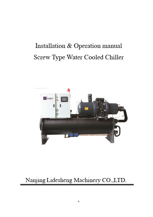
Installation & Operation manualScrew Type Water Cooled Chiller Nanjing Lidesheng Machinery CO.,LTD.ContentPart 1 Installation and maintenance Introduction (2)Schematic drawing for service clearance (3)Schematic drawing for hoisting (4)Setup and maintenance (5)Part 2 Controlling and handling Introduction (12)Part 1 Installation and maintenanceIntroductionMENERGY MSSH serial Water-cooled Screw-type Chiller, which is concisely designed, applies the advanced semi-enclosed dual-screw compressor and the high-effective heat exchange tube with the most updated technologies, and can be controlled through the advanced microcomputer. This product has advantages of stable system, low oscillation, high reliability and high effectiveness on energy saving. MENERGY original anti-reversal program for the compressor can strengthen the running reliability of the chiller. This product has more than twenty types for being extensively applied in many comfortable or technical situations by the customer.Before the chiller is started up, all the related personnel in charge of setup, startup, operation and maintenance should carefully read through this manual so as to know all the precautions onsite.Schematic drawing for service clearanceSchematic drawing for hoisting Single-head:Dual-head:Setup and maintenanceSetup and maintenance of the chiller should only be carried out by a qualified person who has been trained professionally, and is familiar with local standards and rules and has practical operational experience. The trial running of the chiller must be carried out by the professional service supplier to ensure the quality of the chiller.Check before acceptanceAfter the device has arrived, check if all the items listed in the delivery order are complete, and any part damaged during transportation should be informed to the forwarding agent with written form for claim. Before setup, check if the local supply voltage, frequency and so on are complying with the chiller. MENERGY will bear no liability for any damage after the device has been accepted.HoistingHeavy-duty ropes or chains should be used for hoisting through the hoisting holes of the chiller, and the control cabinet and other parts of the chiller should be protected from damage when hoisting (The schematic drawing for hoisting introduced above should be referred to).Environmental requirementThe chiller is suitable to be used in the environment that the surrounding temperature is -15℃ above and the relative humidity is ≤ 95%, and the ground for placement should be horizontal and with enough solidity or reinforcement measures should be taken (The requirements in the schematic drawings of ground base and service clearance for the chiller should be referred to).Water quality requirementAs the composition of local water is complicated, the water quality should be check when some uncommon water (such as industrial waste water, ground water, etc.) is used. If the water quality does not satisfy the requirement for the water used in air-conditioning, the water should be treated according to the Specification for Design of Industrial Re-circulating Cooling Water Treatment or other related standards.Water pipesBoth outlet and inlet of the chiller should be equipped with a stop valve, a thermometer and a pressure gauge for routine check and maintenance of the water system; and both outlet and inlet of the water pump should be equipped with a strainer to prevent impurities from going into the pump or the vessel; before insulating the heat of the water pipe, the sealing of the pipeline should be checked when the water is to go into the chiller; all the pipelines connected with the chiller should be equipped with vibration dampers and flow controllers (such as water flow valves, water pressure difference switch, etc.) as per the requirement; when a device for contamination draining is to be mounted to the water system of the air-conditioning engineering, it should be avoided from the pipelines of the outlet and inlet of the chiller, or the normal operation of the chiller would be disturbed. Schematic drawing for the external water pipeline systemInlet Of The Colling TowerInlet Of The Terminal InstallationOutlet Of The Colling TowerOutlet Of Terminal InstallationPipeline design Installation Notesa)Pipe works must avoid any unnecessary bends and offset(up and down).b)Install gate valve for every joint for service and maintenance.c)Air vent must be installed at the highest position.Open the air vent to realease theair trapped in the water system.d)Water pump must install at water return linee)At the lowest point of the pipe work,install a gate valve drain out water.f)At the highest point of the pipe work,install a manual or automatic air vent.g)Install strainer before water entering to the water pump.h)Flush lot of clean water to remove foreign material before unit start up.i)Pressure gauge and thermometer must be installed at visible and accessiblelocation.Check before starting upWater circuit partCheck all the pipelines of the water system to ensure that the evaporator and the condenser are correctly connected and the water flow direction is correct. Check if the inlet pipe and the outlet pipe of the heat exchanger mentioned above are well connected, and then open all the water valves and start up the corresponded water pump to wash the pipes so as to ensure the water system is clean and check if there is any leakage at the pipes and joints. Discharge the air in the water circuit of the evaporator and the condenser, and the water circuit should be keep clean away from rust. Check the resistance loss at the water side of the evaporator and the condenser against the water volume. Check if the temperature transducers are correctly connected.Electric circuit partCut off the main isolating switch and then check all the startup circuits and control circuits of the control cabinet to ensure all the switches are in off position. Check the power supply to the chiller and the voltage fluctuation range should be within ±10% of the rated voltage shown on the nameplate of the compressor, and the unbalance of the phase voltage should be within 2%. Check if there is enough power supply capacity to ensure the startup and full load running of the chiller. Check if all the electric wires and fuses have the matched specification with the running of the chiller, and finish all the interlock control circuits according to the related electric control drawing. Check and ensure all the ancillary equipments and control equipments for air-conditioning are in normal operation and have enough refrigerating capacity to satisfy the running requirement of the chiller at the first operation.Chiller partMake sure that the engine oil heater of the compressor has been electrified for 24 hours, and examine the oil level through the inspecting mirror of the oil separator, and refill oil if the oil level can not be seen. Fully open the manual stop valve on the sparging pipe and remove the seal bonnet away, and fully open the suction and discharge stop valve and then counterclockwise turn it back for 1/2 circle, and then fully open the liquid supply stop valve and start up the ancillary equipments, the condensed water pump and the refrigerated water pump, and finally check if all the safety control equipments are in original status and if the settings are correct. See <Table 1> below for the related items for checking.Safety equipmentsThe chiller is equipped with safety protective devices to ensure safe running, and if one of the safety protective devices is in operation, an error indicator will turn on, and the corresponded function will stop while the other functions will be still normal. It isrecommended to stop the chiller for troubleshooting to avoid from more serious accident only if any part becomes abnormal. See <Table 2> for the detailed series of the safety protective devices of the chiller.Recommended running rangeRecommended maintenance periodsTroubleshooting for the Screw-type ChillerPart 2 Controlling and handlingAs the leaving water temperature is setting, the operator press start key then the unit will be operating automatically; and it will stop when press stop key. The intervention from operator is not needed during entire process.Rotating test and manual test can be utilized in order to facilitate regulation and repairing.◆Data SupervisionWhen the unit is power on, the unit will check digital and analog input automatically and the unit will adjust the capacity based on the water temperature in time. The data collecting is very fast and its accuracy is high, it will reflect the actual fact.◆TroubleshootingTrouble will be solved immediately via the program and it will make pre-alarm or alarm at the same time. The unit will stop running when the unit occur severe trouble in order to avoid further damage.Safe and Easy to ManageThe protection of setting password is used in order to protect safety and performance of the unit. You can give different authority according to your different requirement, so that you will not be worried about the abnormal damage of unit as the operator or other person exceed their authority. In other words, the unit is safety and easy to manage.。
冷水机、冷水机组操作说明书
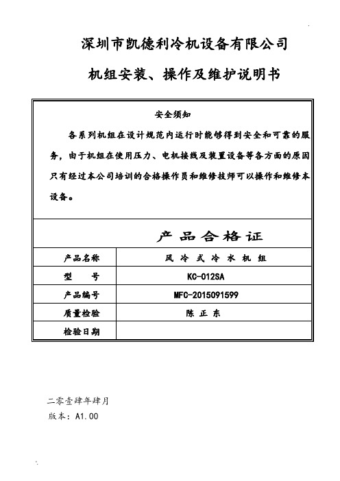
深圳市凯德利冷机设备有限公司机组安装、操作及维护说明书二零壹肆年肆月版本:A1.00目录一、机组的适用范围 (1)二、规格 (1)三、安装说明 (1)四、操作说明 (1)1、使用操作…………………………………………………………………………………… .. 12、面板操作简介 (2)3、用户操作 (2)4、故障显示及排除 (2)五、故障排除 (3)六、保养 (4)七、注意事项 (4)八、电路图……………………………………………………………………(见附页)风冷式冷水机组操作手册一﹑机组适用范围在工业上广泛用于塑料﹑电子﹑化工﹑冶金﹑食品﹑制药﹑电镀﹑皮革﹑工艺和科研等﹔在商业上广泛用于酒店﹑宾馆﹑超级市场和影剧院等。
二﹑规格三﹑安装说明1﹑机器安装﹐要求平放﹐不可倾斜﹔2﹑机器两侧应有一米左右保养空间﹔3﹑冰水管管路务必接成回路﹐使冰水得以循环﹔4﹑冰水管路必须保温﹔5﹑接电源时请确定电源足以承担冷水机组最大负荷﹔6﹑机组电源﹐必须单独控制﹔7﹑必须接地线﹐以确保安全。
四﹑操作說明启动机组前﹐应检查冰水管路阀门是否打开(注﹕长期停机后﹐再次开机前﹐应打开电源24小时后再开启机组)﹔机组控制﹕1、使用操作(面板图)本公司使用微电脑控制器,显示屏为模块式屏幕,。
显示界面的设计充分运用人类工程学原理,使用操作简便直观,操作人员只需稍阅说明书就可上岗操作,其操作面板如图示。
1.1>按键指示灯*COMP1* 压缩机1控制指示灯,灯亮允许启动否则不允许启动,由*COMP1*按键控制.*COMP2* 压缩机2控制指示灯,灯亮允许启动否则不允许启动,由*COMP2*按键控制.*RESET* 有故障时的指示灯(闪烁显示),无故障时按下<RESET>可关闭.*PUMP* 机组运行指示灯,机组运行时此灯亮,否则灭.*0FF* 延时停机指示灯,延时停机时闪烁点亮.*SET* 参数设置指示灯,处于参数设置界面时此灯亮.1.2>面板指示灯*POWER* 电源指示灯,通电后灯亮.*RUN* 机组运行指示器,非待机状态亮.*ERROR* 故障指示灯,有故障时亮.*COMP1* 压缩机1运行指示灯.*COMP2* 压缩机2运行指示灯2、面板操作键简介2.1>面板中间为两个模块显示屏,PV屏显示实际温度,SV屏显示设定温度。
开利19l冷水机组操作中英文对照和故障信息
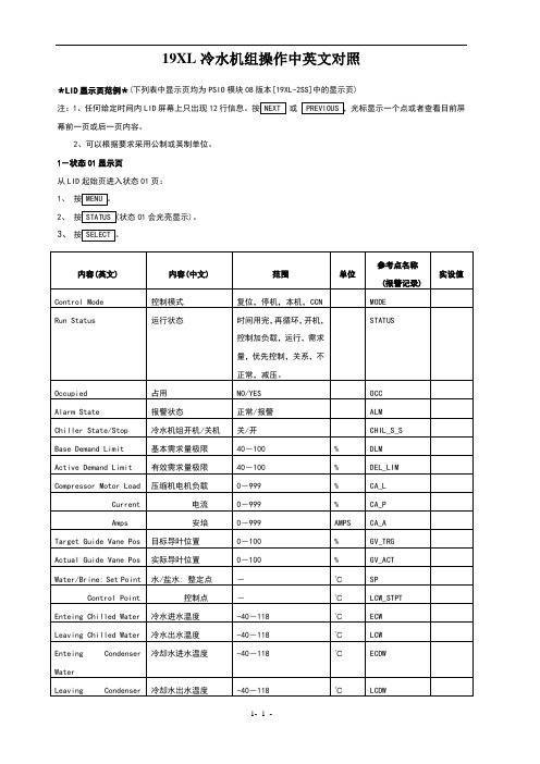
19XL 冷水机组操作中英文对照*LID 显示页范例*(下列表中显示页均为PSIO 模块08版本[19XL-2SS]中的显示页)注:1、任何给定时间内LID 屏幕上只出现12或幕前一页或后一页内容。
2、可以根据要求采用公制或英制单位。
1-状态01显示页从LID 起始页进入状态01页: 1、2、 状态01会光亮显示)。
3、2-状态02显示页要从LID 起始页进入状态02页: 1、2、3、 光标向下移动到STATUS02。
4、3-状态03显示页 由LID 初始页到此页: 1、 2、 3、 向下移动到 STATUS03。
4、 按4-整定点显示页由LID初始页到此页:11-维护(MAINT03)显示页 (注:本维护页不支持优先控制)由LID起始页到本页1、2、4、5、5-整定显示页由LID起始页到本页:1、2、4、5、光标向下找到 CONFIG。
6-服务1显示页由LID起始页到此页:1、2、3、光标向下找到EQUIPMENT SERVICE (设备服务)4、5、光标向下找到 SERVICE1。
6、*注:降压 Reduce7-服务2显示页由LID起始页到此页1、2、3、光标向下找到EQUIPMENT SERVICE (设备服务)。
4、5、光标向下找到 SERVICE2。
6、8-服务3显示页由LID起始页到此页1、2、3、光标向下找到EQUIPMENT SERVICE (设备服务)。
4、5、光标向下找到 SERVICE3。
9-维护(MAINT01)显示页 (注:本维护页不支持优先控制)由LID起始页到本页1、2、3、光标向下移到CONTROL ALGORITHM STATUS (控制器逻辑状态)。
4、5、光标向下移到MAINT01。
10-维护(MAINT02)显示页 (注:本维护页不支持优先控制)由LID起始页到本页1、2、3、光标向下移到CONTROL ALGORITHM STATUS (控制器逻辑状态)。
开利19XL冷水机组操作中英文对照和故障信息
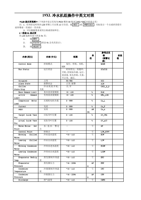
19XL冷水机组操作中英文对照*LID显示页范例*(下列表中显示页均为PSIO模块08)注:1、任何给定时间内LID屏幕上只出现12或前屏幕前一页或后一页内容。
2、可以根据要求采用公制或英制单位。
1-状态01显示页从LID起始页进入状态01页:1、2、状态01会光亮显示)。
3、2-状态02显示页要从LID 起始页进入状态02页:1、2、3、 光标向下移动到STATUS02。
4、3-状态03显示页 由LID 初始页到此页:1、 2、3、 向下移动到 STATUS03。
4、按4-整定点显示页由LID 初始页到此页:11-维护(MAINT03)显示页 (注:本维护页不支持优先控制)由LID 起始页到本页1、 2、3、 光标向下移到 CONTROL ALGORITHM STATUS (控制器逻辑状4、 5、 光标向下移到5-整定显示页 由LID 起始页到本页:1、 2、3、 光标向下找到 EQUIPMENT CONFIGURATION (设备组4、 5、 光标向下找到CONFIG 。
6-服务1显示页由LID起始页到此页:1、2、3、光标向下找到EQUIPMENT SERVICE (设备服务)4、5、光标向下找到SERVICE1。
6、*注:降压 Reduce7-服务2显示页由LID起始页到此页1、2、3、光标向下找到EQUIPMENT SERVICE (设备服务)。
4、5、光标向下找到SERVICE2。
6、8-服务3显示页由LID起始页到此页1、2、3、光标向下找到EQUIPMENT SERVICE (设备服务)。
4、5、光标向下找到SERVICE3。
9-维护(MAINT01)显示页 (注:本维护页不支持优先控制)由LID起始页到本页1、2、3、光标向下移到CONTROL ALGORITHM STATUS (控制器逻辑状态)。
4、5、光标向下移到MAINT01。
10-维护(MAINT02)显示页 (注:本维护页不支持优先控制)由LID起始页到本页1、2、3、光标向下移到CONTROL ALGORITHM STATUS (控制器逻辑状态)。
日立水冷机组液晶屏操作使用说明书
※ 再次点击画面(除菜单项以外的部位),可以隐藏该弹出式菜单的菜单项。 ◇ 主画面按钮:用手指点击该按钮返回到系统主画面。 ◇ 画面名称标签:在画面的上部用红字显示“启停控制菜单”,表示现在停留画面是启停
控制画面。
1
触摸屏的使用注意事项 ------------------------------------------------------------------------------- 2
使用触摸屏的水冷式冷水机组和普通水冷式冷水机组机型对比 -------------------- 2
触摸屏的画面(功能菜单)结构说明 ----------------------------------------------------------
日立ቤተ መጻሕፍቲ ባይዱ水冷螺杆式冷水机组
液晶触摸屏 操 作 说 明 书
Z0010076
广州日立冷机有限公司
技术资料-触摸屏操作使用说明书
目录
液晶显示触摸屏人机界面的概述 -------------------------------------------------------------------------
启停控制画面上有电源、运行/停止、运行状态三个指示灯和机组运行、机组停止、功能菜 单,主画面等工作按钮。另外还有时间、日期显示和画面名称标签。 ◇ 电源指示灯:给机组加电以后当系统电源正常时,此指示灯显示为红色,指示灯闪烁
时表示机组电源异常。 ◇ 运行/停止指示灯:机组在停止状态时指示灯显示为红色,并显示“停止”标签。机组
RCU100SCL2/RCU100SC1 RCU180SCL2/RCU180SCL1
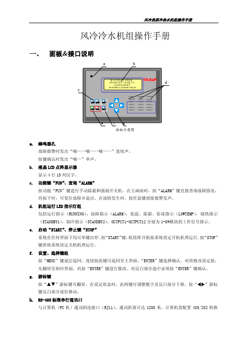
风冷冷水机组操作手册
443 小时
2:冷凝风扇 1 4:1#压缩机
界面 A-11 DO 定义: 7: 冷凝风扇 2 9: 2#压缩机 11:运行指示
8: 2#液路电磁阀 12:报警输出
此界面显示各 DI 的值。 按 键返回 上一界面,按 键进入下一界面。 按 MENU 键返回功能选择界面。
界面 A-12 DI 定义 1:水流开关(仅 1#模块) 2:1#低压保护 3:1#高压保护 4:1#压机风机过载 界面 A-13 DI 定义 5:1#排气温度保护 6:电源故障 7:2#低压保护 8:2#高压保护 9:2#压机风机过载
使用 或 键选择菜单项,选中的 功能项反白显示, 按 ENTER 键确认, 进入相应功能。
A、显示系统状态——实时显示机组 AI 状态、DO 状态、DIN 状态,风机累计运转时间,本机序列号等 参数。
风冷热泵冷热水机组操作手册
功 能 选 择 显示系统状态 修改系统参数 故障查询 界面 A-1 模块组网状态: 组合压缩机数 1台 组网 I/O 模块数: 1 台 界面 A-2 与下位 I/O 单元通讯状态: 通讯正常单元数:3 台 1:通 2:通 3:通 5:断 6:断 7:断 界面 A-3 1 单元 DO 状态: 1:关 2:关 3:关 5:关 6:关 7:关 9:关 10:关 11:关 界面 A-4 1 单元 DIN 状态: 1:通 2:通 3:通 5:通 6:通 7:通 9:通 10:通 11:通 界面 A-5 1#模块 AIN 测量: 1#蒸发/冷凝温度 2#蒸发/冷凝温度 20.2℃ 20.2℃
风冷热泵冷热水机组操作手册
7: 0 次
8: 1 次 此界面显示水泵累计运转时间,按 键返回上一界面,按 键进入下 一界面。 按 MENU 键返回功能选择界 面。 此界面显示各 DO 的值。 按 键返回 上一界面,按 键进入下一界面。 按 MENU 键返回功能选择界面。
- 1、下载文档前请自行甄别文档内容的完整性,平台不提供额外的编辑、内容补充、找答案等附加服务。
- 2、"仅部分预览"的文档,不可在线预览部分如存在完整性等问题,可反馈申请退款(可完整预览的文档不适用该条件!)。
- 3、如文档侵犯您的权益,请联系客服反馈,我们会尽快为您处理(人工客服工作时间:9:00-18:30)。
1 General概述This unit is fitted with the SIEMENS PLC controller together with othermatching electric appliances like imported contactor、thermal relay、airswitch and air switch,ensuring safe running of unit. In order to realizedependable operation of unit ,PLC is fitted with reliable programcontrolled system having application function up to current advancedlevel among the same trade. This unit is characterized byself-operation ,safety and dependability.本机组电气控制系统采用德国SIEMENS公司提供的PLC控制器,其他电器配套有进口接触器、热继电器、空气开关和三相电源监测器,可确保机组安全运行。
为了使机组可靠运行,电脑配置了完善的程序系统,应用功能达到目前同行业先进水平。
本电脑通讯端口采用RS-485信号标准的9针D型连接器,并符合EN50170所定义的PROFIBUS工业现场总线标准,实现计算机联网监控。
本机组有节能,自动运行,安全可靠等特点。
This operation instruction is applicable for the operation of Jirong water chillersof LRSFZ type.本操作指南适用于LRSFZ型风冷冷(热)水机组的操作运行。
2 Preparation before start-up开机前准备Make the following checks carefully before start-up:机组启动之前必须认真检查以下几项内容:Examine the electrical system (de-energized):电气系统的检查(断电检查):The internal parts of de-energized electrical system can be checked. thechecked items cover the tightness of bolts for wires、contactor etc,screwing-up of wiring for comp and reliable connection of plugged –incomponents and PLC module,(confirm if they come loose duringtransportation) to make sure contact well.在确定机组断电情况下,可对电控系统内部进行检查。
主要检查导线、接触器等元件的螺丝接头是否紧固,星三角启动的接线方法是否正确(请参见随机图纸),压缩机接线是否牢固,各接插件及PLC模块连接是否牢固(是否有运输过程的松动)以确保接触良好。
Examine the unit机组的检查See if all the valves and safety locks are open, confirm if the controllerwith manual reset is at the reset state.所有安全锁和阀门是否打开,带手动复位的控制器是否已经复位。
Energize the system for examination:通电检查:Make the circuit breaker inside the unit to be at OFF state, and then energizethe system with AC380V±5% power supply having voltage difference ratebetween phases ≤3%, at this time , i f the system is normal, the indicator forcomputer should response to this. Start the contactor of supply fan orcondensing fan , then initiate the main power supply of supply fan andcondensing fan check whether the phase order is in compliance with that of thisunit, otherwise, change the phase order in the exterior power supply.将机组内部断路器置于OFF状态通入AC380V 5%,三相不平衡度≤3%的电源,通电后电脑指示灯应有反应。
如无反应则检查相序是否与本机相序相符(内部有三相电源监测器),请在总电源调换相序。
再接通冷凝风机主电路,检查冷凝风机转向,通常冷凝风机相序与三相电源监测器相序同步。
Prior to start of unit, the comp crankcase should be pre-heated for 8 hours.机组启动之前,要求压缩机曲轴箱预加热8小时。
3 How to operate computer电脑操作方法The touch display screen and its display触摸屏面板及显示说明:The display language adopt English version. You can check information andchange parameter easily according to requirement.所有画面均采用英文显示。
您可以根据需要查看信息和修改参数。
The model of touch screen adopted is KTP178, which is manufactured bySIEMENS corporation. When touch screen is powered, the power indicatinglight is on; the operation indicating light flash. When you do not touch thescreen a definite period, the screen will enter energy-saving status (backgroundlight will be off), if the touch screen is touched again, background light shall beturned on and display picture.此触摸屏为SIEMENS公司所产的KTP178,当您在一定的时间内没有触摸屏幕,屏幕将会进入节能状态,关闭背光灯,此时只需再次触摸屏幕,即可打开背光灯,正常显示画面。
Operation method操作方法After the system is checked, the power-supplying method meet requirement, theconnection is right, can enter startup and operation. First check the switch ofPLC controller whether or not on “run” status (setup when ex-work), makecontroller enter operation status, the indicating light of PLC will on. After being powered, the power indicating light is on, the operation indicating light flash.The main picture appear, displaying the current unit status, time temp. and other measuring value.系统检查完毕,供电方式能满足要求,接线无误,可进入开机操作。
首先检查接通机组内部断路器,PLC控制器上的开关是否拨到“RUN”位置(出厂设置),使控制器进入运行控制,电脑指示灯亮。
当触摸屏通电有显示后,即可出现初始屏幕,显示机组的软件编号,再触摸屏上任意位置出现主屏幕,显示当前机组状态、时间和温度。
触摸“开/关”后显示“开机状态”就表示开机运行,同样触摸“开/关”后显示“关机状态”就表示关机。
如果机组有故障将出现报警信息。
具体显示主屏幕如下:Local ON/OFF control近控机组启停控制After touch the “ON/OFF” menu, the following picture displays:触摸“ON/OFF”后,显示如下画面:Touch the menu“LOCAL CONT. ON/OFF”, “Unit RUN” displays, it means the unit has been started-up,to stop the unit, touch the“LOCAL CONT.ON/OFF”, then“Unit STOP”displays, it means unit is stopped.触摸“LOCAL CONT. ON/OFF”后显示“Unit RUN”表示开机运行,同样触摸“LOCAL CONT. ON/OFF”后显示“Unit STOP”表示关机。
操作完成后应尽快退出该画面,以避免误操作。
Export water temperature set:出水温度设定:T he following picture shall be display after the“Temp. SET” has been touched.触摸“Temp. SET”后显示如下画面:The set range of Chilled water temperature is 5~15℃,default value is 7℃;the set range of Hot water temp.set is 35~50℃,default value is 45℃。