
电源模块说明书
电源模块说明书
摘要:本文对符合工业标准的MRCL-PW30242A电源模块进行深入介绍。
一、概述
MRCL-PW30242A电源模块是爱默尔智能照明TLC3000系列中的总线供电系统,能向总线提供24V/2A的电源,4个RJ45接口可以组成二口网桥。
二、功能特点
1.向总线提供24V/2A电源
2.具有二口RS485网桥功能
3.标准35mm导轨式安装结构
三、型号及其含义
MRCL –PW 30 24 2A
四、主要技术参数
●输入电源:AC220V±10%
电源频率:50HZ
●整机无负载功耗: W
●输出电压:DC24V
●输出电流:2A
●环境条件:工作温度:-10℃~+40℃
工作湿度:20%~80%
储存温度:-40℃~+55℃
储存湿度:10%~95%
●外形尺寸:234mm×88.4mm×70.3mm 模块输出电流为2A
模块输出电压为24V TLC3000系列产品。
“POWER”电源模块。
爱默尔智能照明系统。
五、外形及安装尺寸(见图1)
六、设备参数设置
1.面板部分(见图2)
地址
功能
① 1~8按键/指示灯
按键:无效
指示灯作用:指示灯1-当网桥1端口接收到数据时闪烁;
指示灯2-当网桥1端口发送数据时闪烁;
图 2
指示灯3-当网桥2端口接收到数据时闪烁;
指示灯4-当网桥2端口发送数据时闪烁;
指示灯5~8-无效;
②地址按键/指示灯
按键:无效。
指示灯:无效。
③功能按键/指示灯
按键:无效。
指示灯作用:作为电源指示。
2.侧板部分(见图3)
图 3
前后两侧板设有通风孔和接线孔,标识为接线规定。
①L、N为本模块继电器专用电源AC220V~240V输入端。
注:电源AC220V~240V必须通过断路器接入。
②RJ45接口为485总线接线端。
注:同侧的两个RJ45接口不具有网桥作用而只作为直通连接作用,对角的两组RJ45接口具有网桥作用。
七、安装和接线
1、安装条件
安装位置要通风良好,注意防潮、防震、防尘。
电源AC220V~240V必须通过断路器接入。
1、接线规则
本模电源输入端连接线:不小于1mm2铜导线
485总线连接线:采用超五类线(RJ45接口)
2、RJ45接线方式
1-棕白 2-橙白 3-绿白 4-棕 5-橙 6-绿 7-蓝 8-蓝白
3、RS485总线定义
485总线(超五类线)与信号对应关系:DC24V →棕、橙、绿
信号+→蓝
信号-→蓝白
公共端→棕白、橙白、绿白八、电源设计说明
1.电源模块容量
本电源模块电源输出为24V/2A,根据TLC3000系列产品的功耗可以估算
出本电源
模块最多能带40个TLC3000系列的产品。
2.电源线路长度的估算
假定电源连线在各个模块之间是等距离分布,则电源线路总长度和模块
数目必须符合下面公式:
L(N+1)<6000
其中:L-线路总长度,N-模块总数量
由此公式可以看出,所连模块数目越大电源线路的长度越短。
九、安全使用与维护保养
1.使用前详细阅读所有说明。
2.勿靠近干扰设备。
3.要建立良好通风散热环境。
4.在使用过程中,注意防潮、防震、防尘。
5.严禁雨淋、接触其它液体或腐蚀性气体。
6.机器出现故障时,请与专业维修人员或本公司联系。
7.定期除尘,不能用酒精、汽油等挥发性液体擦拭。
8.如受潮或被液体侵袭,应及时进行干燥处理。
9.定期检查线路的受损和老化程度,应及时更换不合格线路。
XL1513 12V转5V电源模块使用手册说明书
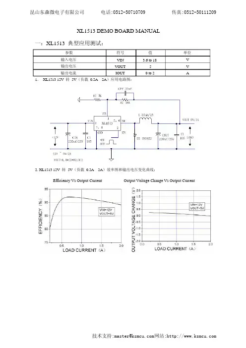
Output Voltage Change Vs Output CurrentEfficiency Vs Output Current2. XL1513 12V 转 5V (负载 0.2A—2A )效率图和输出电压变化曲线:1. XL1513 12V 转 5V (负载 0.2A—2A )应用电路图:AV V 单位 0 to 253.6 to 18值IOUTVOUT VIN 符号输出电流输出电压 输入电压 参数一:XL1513 典型应用测试:XL1513 DEMO BOARD MANUAL反面正面XL1513PCB 图:大电流走线要粗,短,不拐弯反馈点要接到输出滤波电容 C2,COUT 之后输入电解电容 CIN ,陶瓷电容 C1 布局布线要紧靠芯片 7,8(GND )和 4(VIN )(1)流大电流的线要粗,短,不拐弯。
(2)7,8 脚(GND ) 脚(VIN )线要粗,短线,不拐弯,且输入电解电容 CIN 和 105 C1,4 陶瓷电容紧挨第 4 脚(VIN )和 7,8 脚(GND)。
(主要是为了减小输入电源布线寄生的电感, 电阻产生的高压开关毛刺干扰)(3)5,6 脚(SW )输出线要粗,短线,不拐弯,电感和续流二极管要紧挨第 5,6 脚(SW ) 输出端。
(4) 脚1 (FB )走线要接到输出滤波电容 C2,COUT 之后, PCB 布线远离 L1,D1,避免噪声干扰。
二:XL1513 PCB 板布局建议:三:XL1513 温度测试数据1:XL1513 电路图和 PCB 版图。
XL1513 温度测试点电感(L1)温度测试点输入电容(CIN)温度测试点输出电容(COUT)温度测试点肖特基二极管(D1)温度测试点2:XL1513 DEMO 板工作时(12V 转 5V)各元件温度,自然通风,室温:16℃。
输出负载电流 1.5A2A0.2A0.5A1AXL1513电感(33uH/2A)31℃20℃22℃25℃36℃26℃19℃21℃23℃29℃肖特基二极管(IN5822)26℃19℃20℃22℃29℃输入电容(35V/220uF)22℃17℃18℃20℃26℃输出电容(35V/220uF)21℃18℃18℃19℃26℃昆山东森微电子有限公司电话**************传真**************。
奥特迅通信电源充电模块说明书
8.1 开机 ················································································································ 10 8.2 关机 ················································································································ 10 8.3 主画面显示 ···································································································· 10 8.4 参数设置操作 ································································································ 11 8.5 模块校验 ········································································································ 13 8.6 多机并联运行 ································································································ 14 8.7 自动 / 手动 ·································································································· 14
安美乐TCP(TC) 控制电源模块安全使用说明说明书
目 录 (01)关于说明书 (02)TCP(TC)控制电源模块安全使用说明 (02)涉及的其它说明书 (02)安全警示说明 (03)免责声明 (03)第一章产品说明 (04)1.1 产品简介 (04)1.2 设计及功能 (05)1.3 性能指标 (06)1.4 订货资料 (06)第二章安装连接 (07)2.1 TCP控制电源模块的安装连接 (07)2.1.1 连接TCP-100、TCP-240控制电源模块和TD驱动模块 (07)2.1.2 D15外控通讯接口 (07)2.1.3 连接供电电源 (08)2.1.4 安装环境要求 (08)2.2 TC-100控制模块的安装连接 (08)2.2.1 连接TC-100控制模块和TD驱动模块 (08)2.2.2 D15外控通讯接口 (09)2.2.3 安装环境要求 (09)第三章 操作方法 (10)3.1 TCP控制电源模块的操作方法 (10)3.1.1 连接TCP-100、TCP-240控制电源模块和TD驱动模块 (10)3.1.2 操作与显示 (10)3.2 TC-100控制模块的操作方法 (14)3.2.1 连接TC-100控制模块和TD驱动模块 (14)3.2.2 操作与显示 (14)第四章售后服务 (15)产品保修单 (16)关于说明书TCP(TC)控制电源模块安全使用说明在安装与使用TCP(TC)控制电源模块前,操作人员都应仔细阅读本说明书,并按照说明书中规定的条款安装与操作,以免造成人员伤害与设备损坏。
本说明书适用于TC-100控制模块、TCP-100和TCP-240控制电源模块及其后续改进型号。
因上述产品技术改进或说明书改版等原因导致的内容更新,本公司恕不另行通知,敬请谅解。
相关信息可登录中科科仪官方网站查询,网址:,或与本公司联系!本说明书版权及由本说明书引起、产生和包含的与“KYKY”相关知识产权归北京中科科仪股份有限公司所有,任何单位或个人未经授权不得擅自使用。
台达电源模块说明书
台达电源模块说明书一、引言台达电源模块是一种高效、可靠的电源设备,能够为各种电子设备提供稳定的电力供应。
本说明书将详细介绍台达电源模块的特点、技术参数、安装使用方法、维护保养等相关内容,帮助用户正确、安全地使用该产品。
二、特点1. 高效性能:台达电源模块采用先进的开关电源技术,具有高效转换率和低功耗特点,能够最大限度地提供电能利用率,减少能源浪费。
2. 稳定可靠:台达电源模块具备过载保护、短路保护、过压保护等多重安全保护功能,能够有效防止因外界因素导致的电源故障,保障设备的正常运行。
3. 安装便捷:台达电源模块采用模块化设计,体积小巧,安装方便,可灵活应用于各种设备中,适用于不同场景的需求。
4. 高度兼容性:台达电源模块具有良好的兼容性,能够适应各种输入/输出电压需求,满足不同设备的电源供给要求。
三、技术参数1. 输入电压范围:台达电源模块的输入电压范围广泛,通常为AC100-240V,能够适应全球不同地区的电网电压。
2. 输出电压范围:台达电源模块的输出电压范围可根据用户需求进行调整,通常为DC 12V-48V,能够满足不同设备的电源供应要求。
3. 转换效率:台达电源模块的转换效率高达90%以上,能够将输入电能有效转换为输出电能,最大限度地减少能源损耗。
4. 工作温度范围:台达电源模块适用于不同的工作环境温度,通常工作温度范围为-20℃至+60℃,能够在恶劣的环境条件下正常工作。
四、安装使用方法1. 安装前准备:在安装台达电源模块之前,需先检查输入电压是否符合要求,并确保设备处于停电状态。
2. 安装步骤:(1) 将台达电源模块的输入端与交流电源连接,确保接线牢固可靠。
(2) 将台达电源模块的输出端与设备的电源接口连接,确保接触良好。
(3) 检查各个连接处是否牢固,避免松动或接触不良。
3. 使用注意事项:(1) 请勿将台达电源模块长时间暴露在潮湿、高温或有腐蚀性气体的环境中。
(2) 在使用过程中,如发现异常情况(如异味、异常声音等),应立即停止使用并联系售后服务部门。
RT10A230X电源模块说明书

润海通科技RT10A230X整流模块用户手册深圳市润海通科技有限公司目录1.模块功能特点 (1)2.模块技术指标 (2)3.模块工作原理 (3)4.模块外形特点 (4)5.模块功能说明 (5)6.显示说明 (6)7.操作流程 (8)8.操作说明 (8)9.模块外形及安装图 (9)RT10A230X 整流模块§1 模块功能特点l LCD 汉字显示,模块工作状态和工作参数一目了然,通过RS485接口,在系统主监控工作时,模块接收主监控发出的工作参数,无主监控器时,可以在模块面板上方便地设置模块工作参数。
l 软件校准技术:传统模块参数整定都采用电位器整定,但存在固有缺陷,如电位器漂移以及现场调整不便等问题;我公司生产的RT10A230X 模块采用软件校准技术,模块内部没有一个电位器,通过按键和LCD 显示可以校准模块输出电压、输出限流、电压测量、电流测量,模块参数整定方便快捷。
l 自主均流技术:模块采用自主均流技术,模块间均流偏差小于3%。
l ZVS 软开关技术:为了使开关电源能够在高频下高效率地运行,我公司不断研究开发高频软开关技术,已开发成功ZVS 边缘谐振技术,使开关过程损耗大为降低,从而进一步减小体积、减轻重量、极大地提高模块性能。
1.1ZVS 软开关优点² 开关损耗小² 可实现高频化(极限頻率可做到1-2MHz)、开关过程在平滑状态下实现 ² 恒频运行,谐波成份小 ² 无吸收电路 ² 电流、电压应力小 1.2 ZVS 软开关基本原理硬开关过程和软开关开关过程比较如下图:功率MOSFET 损耗由三部分组成:开通损耗、关断损耗和导通损耗,硬开关在开关过程硬开关过程 ZVS 软开关过程中电压和电流同时变化,即存在高压大电流的状态,此时损耗很大,一般需要加吸收电路减小开关损耗,另外在关断过程中,Vds会出现过冲,对功率管有较大的损害。
ZVS软开关开关过程中,开通时Vds降到0V时电流上升,关断时电流降到0A时Vds上升,因而理论上无开关损耗,实际中Vds和电流变化有一定的重叠,但开关损耗和硬开关相比较大大降低。
300W AC DC 电源模块说明书

300W,165-264V AC Input,Dual outputAC/DC battery charging module power supplyRoHSFEATURES●Specially designed for Distribution Automation terminal design,suitable for 220Vdc operating mechanism,and it can charge for capacitor of 50000uF/250V ●Maximum instantaneous power up to 340W●With charging function,the 24V (6-30AH)output Lead-acid battery can be charged,when system connected with battery,it can be used as uninterrupted power supply●Designed in accordance with the power-related requirements of the State Grid Corporation,the main technical indicators meet the relevant industry standards●Battery reverse polarity protection,battery under voltage protection●Output over-current,over-voltage protection ●2.5KVAC high isolation voltage●Industrial grade operating temperature:-40℃to +70℃●Chassis mountingMBP300-2A27D27220is AC/DC battery charge power converter offered by Mornsun.It features wide input voltage range,taking both DC and AC input voltage,output over-current,over-voltage protection,strong ability in adapting power grid.This product has power working status display and Intelligent charging function,it can used to charge the 24V lead-acid battery,when AC is power-off,the battery can supply power to the load;it has battery over discharge protection function,Designed specifically for distribution automation terminal (DTU /FTU).It is widely used in the power industry switch substations,power substation,RMU,Intelligent Package Substation,Intelligent Switch Controller and other industries which need uninterrupted power supply.Selection GuidePart No.Output PowerNominal Output Voltage and Current Maximum Output PowerEfficiency(220VAC,%)(Vo1/Io1)(VB/IB)(Vo2/Io2)MBP300-2A27D2722062.5W27V/1.0A27V/0.5A220V/0.1A340W(No more than 20s,5mins once )80(Io1=1A,Io2=0.1A,disconnect the battery)Input SpecificationsItemOperating Conditions Min.Typ.Max.Unit Input Voltage Range AC input 165220264V AC DC input200310370VDC Input Frequency 475063Hz Input Current 220V AC,Typical load -- 1.0--AHot PlugUnavailableOutput SpecificationsItemOperating Conditions Min.Typ.Max.UnitRated Output CurrentInput voltage range Io1--1--A Io2--0.1--Peak Output Current *Input voltage range Io1(No more than 20s,5mins once,Io2≤0.1A)----6Io2(No more than 20s,5mins once,Io1≤1A)---- 1.36Output Voltage Input voltage range Vo1(Disconnect the battery)--27--VDC Vo2(Adjustable)200220240Line RegulationFull loadVo1--±0.5--%Vo2--±1--Load Regulation0%-100%load Vo1--±1--% Vo2--±5--Ripple&Noise**20MHz bandwidth(peak-to-peak value)(Io1=1A,Io2=0.1A,disconnect the battery)Vo1--200300mVVo2--2000--Floating Charge Voltage Room temperature,Io1=1A,Io2=0AVB--27--VDCBattery Charge Current Room temperature,Io1=1A,Io2=0AIB--0.5--A Battery Discharge Cut-off point Typical load Vo120.52121.5VDC Battery Discharge Cut-off Delay Time Typical load--3--sBattery Reverse Polarity Protection The green and the red lights are turn off,when the battery has been connected.Short Circuit Protection Input voltage range,disconnect the battery Hiccup,Continuous,self-recovery Over-current Protection Input voltage range,disconnect the battery Io1--16--A Over-voltage Protection Input voltage range,disconnect the battery----34VDC Hold-up Time Room temperature,220V AC input,Po=20W--0.3--s Note:*①When the ambient temperature exceeds50℃,Io1and Io2single peak current continuous output time can not exceed15s;②Io1and Io2can not simultaneously output peak current,product peak output power should not be more than340W.(Battery charging power included) **Ripple and noise are measured by“parallel cable”method,please see AC-DC Converter Application Notes for specific operationGeneral SpecificationsItem Operating Conditions Min.Typ.Max.UnitIsolation Voltage Input-outputTest time:1min,leakage current setting value:5mA2500----VAC Input-case2500----Output-case2500----Output-output1500----Impulse Voltage Input-output Apply5kV impulse test voltage between input andoutput.Add1.2/50us impact waveform,includingthree positive impulse and three negative impulsewhose time interval is no less than5seconds.And thereshould not have disruptive discharge during the test.5000----V Input-case5000----Output-case5000----Isolation Resistance Input-output Room temperature50----MΩInput-case Room temperature50----Output-case Room temperature50----Operating Temperature*-40--+70℃Storage Temperature-40--+85Shell Operation temperature*----+80Storage Humidity----95%RH MTBF MIL-HDBK-217F@25℃>100,000hNote:*①When the ambient temperature exceeds50℃,it should be taken the cooling method of force air cooling or post cooling to ensure that the module shield temperature is not more than80℃.②When the ambient temperature is lower than-10℃,the product should be operated with rated load for1mins,before it output340W peak power. Physical SpecificationsCasing Material MetalPackage Dimensions200.00*102.00*45.00mmWeight850g(Typ.)Cooling method Free air convectionEMC SpecificationsEMS ESD IEC/EN61000-4-2Contact ±8KV Perf.Criteria B RS IEC/EN61000-4-330V/m perf.Criteria A EFT IEC/EN61000-4-4±4KV perf.Criteria B Surge IEC/EN61000-4-5line to line±2KV/line to ground±4KV perf.Criteria B CS IEC/EN61000-4-610Vr.m.s perf.Criteria A Voltage dips,short interruptionsand voltage variations immunityIEC/EN61000-4-110%,70%perf.Criteria BPrinciple block diagramFig1.Internal principle diagram Wiring Description1.Wiring diagram2.Terminal DefinitionTerminal No.Terminal name Definition1AC(L)AC input L phase2Protective grounding3AC(N)AC input N phase4-Vo1(B-)Control unit(-)Battery input(-)5B+Battery input(+)6+Vo1Control unit(+)7NC No electrical connection 8+Vo2Operating mechanism(+) 9-Vo2Operating mechanism(-) 10NC No electrical connectionManual Instruction1.Power supply status indicatorCharge,AC input power,green light on,the battery is in charging or floating charging status.Discharge,AC input power off,green light off,red light on,the battery is in discharging status.Reverse,when the input voltage off(or input voltage normal,Vo1and Vo2output normal),but the green and red light are all off,which shows that the battery is polarity reversed.Please check the wiring diagram to re-connect the battery.Input voltage(V AC)Output voltage(VDC)Whether to connectthe batteryLEDPower state Vo1Vo2green light Red light22027220no connect on off Output normal220Batteryvoltage220connect on off Output normal,battery charging000no connect off off No output000connect off on No output,battery access to normal220→0Batteryvoltage220connect on→off off→onOutput normal,battery from charginginto the discharge000connect off off No output,reverse connection ofbattery22027220connect off off Output normal,reverse connection ofbatterye of PowerThe power supply can work when input is AC the alternating current.The power input current to load is powered by power supply, meanwhile charge battery in constant current and voltage.After the battery is charged,power supply to floating charge state automatically,this moment,the power supply float voltage and current to normal self discharge of battery.When AC input voltage off,the battery will continue to power for load,0switch time.When the battery output voltage is lower than the under voltage protection point and last for3-10S,the power supply will turn off automatically.Without AC input,pass external passive nodes make Vo1and B+in short circuit(short circuit time:1-2S,but pin should not be short for a long time,otherwise the battery will lose the protection function.)that can enable the battery to start the output.Vo2output Voltage:200Vdc–240Vdc continuously adjustable,The user can adjust the output voltage to the knob with“output voltage adjustment”.e of BatteryThe power supply can be equipped with24V,6-30AH lead acid battery or colloidal maintenance-free battery,The battery is connected to the battery terminal(B+、B-)of the power supply.We should make sure that the input voltage is off before connect or disconnect the battery.If the red light on after connected the battery,the battery connected normal;if the red light off when connected the battery,the battery polarity connected reverse,please check the wiring diagram to re-connect it.It is forbidden to short-circuit the battery.After connect with the battery,the over-current protection and short-circuit protection of Vo1will be disabled.Simple calculation of battery charging time:Battery capacity C(AH)/Charging current(A)Dimensions and Recommended LayoutAttention Matters in Application(1)Output please use wire that cross area is more than2.5mm²,input terminal should add10A/250V AC Fuse.(2)Please correct connection according to the wiring diagram,do not connect wrongly,AC input terminal is strictly prohibited connected with other terminals wrong,otherwise will cause permanent damage to power.(3)Vo2output peak current can not be long term work.(4)To further reduce the Vo1output ripple noise,the user can in the Vo1output parallel connection with one470–1000uF/50V electrolytic capacitor and1uF multilayer ceramic Capacitor.(5)The output of this product is not allowed to work in parallel.(6)The PE terminal of this product should be reliably connected to the earth,in order to improve the capability of anti-interference.(7)Casing will distribute heat when the power is during operating,in order to ensure the power dissipation is good,please keep a certain gap around the power supply to ensure the air flow smoothly,the temperature sensitive device as far as possible from the power.Note:1.Packing information please refer to Product Packing Information which can be downloaded from .Packing bag number:58220041;2.If the product is not operated within the required load range,the product performance cannot be guaranteed to comply with all parameters in the datasheet;3.Unless otherwise specified,parameters in this datasheet were measured under the conditions of Ta=25℃,humidity<75%with nominal input voltage and rated output load;4.All index testing methods in this datasheet are based on our Company’s corporate standards;5.We can provide product customization service,please contact our technicians directly for specific information;6.Specifications are subject to change without prior notice.Mornsun Guangzhou Science&Technology Co.,Ltd.Address:No.5,Kehui St.1,Kehui Development Center,Science Ave.,Guangzhou Science City,Luogang District,Guangzhou,P.R.China Tel:86-20-38601850-8801Fax:86-20-38601272E-mail:***************。
SITOP电源选择模块设备手册说明书
SITOP 电源选择模块设备手册SITOP select6EP1961-2BA00 SITOP PSE200U 3A 6EP1961-2BA11 SITOP PSE200U 10 A 6EP1961-2BA21 SITOP PSE200U 3 A 6EP1961-2BA31 SITOP PSE200U 10 A 6EP1961-2BA41 概述安全提示 1 说明、设备结构、尺寸图 2 安装/拆卸 3 安装位置,安装距离 4 安装 5 技术数据 6 安全、认证、EMC 7 环境条件8 环保9 服务与支持10Siemens AGDivision Process Industries and Drives Postfach 48 4890026 NÜRNBERG C98130-A7579-A1-1-5D29Ⓟ 01/2015 本公司保留更改的权利Copyright © Siemens AG 2014.保留所有权利法律资讯警告提示系统为了您的人身安全以及避免财产损失,必须注意本手册中的提示。
人身安全的提示用一个警告三角表示,仅与财产损失有关的提示不带警告三角。
警告提示根据危险等级由高到低如下表示。
危险表示如果不采取相应的小心措施,将会导致死亡或者严重的人身伤害。
警告表示如果不采取相应的小心措施,可能导致死亡或者严重的人身伤害。
小心表示如果不采取相应的小心措施,可能导致轻微的人身伤害。
注意表示如果不采取相应的小心措施,可能导致财产损失。
当出现多个危险等级的情况下,每次总是使用最高等级的警告提示。
如果在某个警告提示中带有警告可能导致人身伤害的警告三角,则可能在该警告提示中另外还附带有可能导致财产损失的警告。
合格的专业人员本文件所属的产品/系统只允许由符合各项工作要求的合格人员进行操作。
其操作必须遵照各自附带的文件说明,特别是其中的安全及警告提示。
由于具备相关培训及经验,合格人员可以察觉本产品/系统的风险,并避免可能的危险。
Digilent PmodREG1 电源模块说明书
D i g i l e n t P m o d RE G 1™ V o l t a g e R e g u l a t o r M o d u l e R e f e r e n c e M a n u a l®Revision: November 06, 2006215 E Main Suite D | Pullman, WA 99163(509) 334 6306 Voice and FaxDoc: 502-096page 1 of 2Copyright Digilent, Inc. All rights reserved. Other product and company names mentioned may be trademarks of their respective owners.Figure 1Digilent PmodREG1OverviewThe Digilent PmodREG1 is a small form factor voltage regulator able to provide up to 250mA of current at 3.3V. It is specifically designed to work with the Digilent Pmod modules and small embedded control boards, such as the Nanocon, ServoMini, or PmodSF, but is also useable as a general-purpose voltage power supply module.Features include:∙ 250mA low dropout linear regulator ∙ fixed 3.3V output voltage∙ input voltage range of 3.8V-16V ∙ small form factor (0.80” x 1.20”).Functional DescriptionThe PmodREG1 is intended to provide power to Digilent Pmod peripheral modules when they are being used for stand-alone operation not connected to a Digilent system board, or as the power supply for small embedded control modules, such as the Nanocon, that do not have an integral power supply.The Digilent Pmod modules use a six-wire interface made up of four data signals, power, and ground. The PmodREG1 is designed to function as a pass-through module that will pass the four data signals through itself and provide power on the power and ground pins.The input voltage to the regulator is connected via screw terminal connector J3. Any voltage source between 3.8V and 16V can beconnected here. Observe proper polarity when connecting the input voltage source to J3. Digilent has available a coax power jack with pigtail wires that is suited for connecting a normal Digilent switching power supply to the PmodREG1 for operation from power mains.Alternatively, battery packs, also available from Digilent, can be attached to provide the input voltage source.The output voltage from the regulator will appear on pin six of connector J2 and on the VCC pin of the 2-pin header J4. Jumper block JP1 controls whether the output voltage also appears on pin six of connector J1. If ashorting block is installed on JP1, the regulator output is connected to J1 too. To disconnectDocument Title Digilent Confidential Digilent, Inc. the regulator output from J1, remove theshorting block on JP1.The 2-pin header, J4, can be used to takepower from the PmodREG1 module to poweranother device via a two-wire MTE cable.Many Digilent embedded control boards andPmod module boards are equipped with a two-pin connector as an optional way to providepower to the board. Copyright Digilent, Inc. Page 2。
英威腾AX-PWR 电源模块用户手册说明书
AX-PWR电源模块用户手册感谢您购买英威腾电气股份有限公司自主研发、生产的AX-PWR电源模块。
电源模块AX-PWR可配合CPU模块AX70-C-1608P或同类型产品使用。
可提供24VDC,2A的直流电源输出。
本手册主要描述该产品的规格、特性及使用方法等。
为了更安全的使用AX-PWR电源模块产品,敬请您在使用该产品前,仔细阅读本手册。
本公司保留对产品不断改进的权利,资料版本请以英威腾公司网站(/)最新公布为准,恕不另行通知。
1、安全注意事项在开始使用之前,请仔细阅读操作指示、注意事项,以减少意外的发生。
负责产品安装、操作的人员必须经严格培训,遵守相关行业的安全规范,严格遵守本手册提供的相关设备注意事项和特殊安全指示,按正确的操作方法进行设备的各项操作。
2、产品信息2.1 型号与铭牌图 2.1产品铭牌AX–PWR电源模块AX系列图 2.2产品型号2.2 接口描述图 2.3电源模块接口示意图AX-PWR电源模块包含输入、输出两个端口,使用方式参见下表:3、技术参数3.1 一般规格3.2 系统电气规格4、机械设计参考4.1 安装尺寸图4.1安装尺寸(mm)4.2 电气设计参考●以上线耳适用于电源模块,线缆要求额定温度为75℃以上;●接地线缆应使用截面积2mm2以上的线缆。
4.2.2 线缆制作线缆制作步骤:●在电缆顶端,剥除电缆绝缘层,确保铜线裸露长度达到6mm;●将电缆穿入对应线号的套管中;●将裸露的6mm铜线端子穿入线耳圆形孔中,并使用线耳厂商推荐的压线钳压接;●穿入20mm长的φ3热缩套管,完全包裹覆盖铜管部分后热缩处理。
图 4.2线缆制作示意4.2.3 接线注意事项1、进行对输入线缆及接线端子的任何操作前,必须首先确保外部电源处于关闭状态,防止触电及模块损坏;2、 100V/240V交流电源电缆应使用1.0mm2~2.5mm2的导线,并在连接端子处扭绞导线,以较短的长度接入端子,防止螺丝松动等情况下造成短路;3、不要将100V/240V交流电源电缆与直流24V、信号线缆、通讯线缆等捆扎在一起,在空间允许的范围内保持较远的距离;4、配线只能选用75℃以上的铜导线,电源端子螺丝扭力为;5、当AX-PWR电源模块应用于强干扰源的环境(如变频器),建议增加额外的噪声滤波器抑制干扰噪声,详见绝缘变压器;9.5kgf.cm6、 电源接通后,24VDC 指示灯亮表明电源处于工作状态,如不亮,请考虑电源输入异常及模块故障可能。
DC DC 电源模块 URB_S-6WR3 系列 说明书
选型表认证产品型号输入电压(VDC)输出满载效率②(%)Min./Typ.最大容性负载(µF)标称值(范围值)最大值①电压(VDC)电流(mA)Max./Min.CEURB2403S-6WR324(9-36)403.31350/076/781800URB2405S-6WR351200/080/821000URB2409S-6WR39667/082/84470URB2412S-6WR312500/084/86470URB2415S-6WR315400/085/87220URB2424S-6WR324250/083/85100注:①输入电压不能超过此值,否则可能会造成永久性不可恢复的损坏;②上述效率值是在输入标称电压和输出额定负载时测得。
输入特性项目工作条件Min.Typ.Max.单位输入电流(满载/空载) 3.3V 输出--238/5245/12mA5V 输出--305/5313/12其他--305/10313/16反射纹波电流--50--冲击电压(1sec.max.)-0.7--50VDC启动电压----9输入欠压保护 5.56.5--输入滤波类型电容滤波热插拔不支持遥控脚(Ctrl )*模块开启Ctrl 悬空或接TTL 高电平(3.5-12VDC)模块关断Ctrl 接GND 或低电平(0-1.2VDC)关断时输入电流--610mA注:*Ctrl 控制引脚的电压是相对于输入引脚GND。
输出特性项目工作条件Min.Typ.Max.单位输出电压精度①5%-100%负载--±1±2%线性调节率满载,输入电压从低电压到高电压--±0.5±1负载调节率②5%-100%的负载--±0.5±1.5瞬态恢复时间25%负载阶跃变化,标称输入电压--300500µs 瞬态响应偏差3.3V/5V 输出--±5±8%其它电压--±3±56W ,超宽电压输入,隔离稳压单路输出SIP 封装,DC-DC 模块电源专利保护RoHS产品特点●超宽输入电压范围(4:1)●效率高达87%●空载功耗低至0.12W ●隔离电压1600VDC●输入欠压保护,输出短路、过流保护●工作温度范围:-40℃to +105℃●小型SIP 封装●国际标准引脚方式●通过EN62368认证URB_S-6WR3系列产品输出功率为6W ,4:1超宽电压输入范围,效率高达87%,1600VDC 的常规隔离电压,允许工作温度-40℃to +105℃,具有输入欠压保护,输出过流、短路保护功能,广泛应用于医疗、工控、电力、仪器仪表、通信等领域。