REE-OAT变桨系统现场调试手册
变桨调试0423
1.5MW变桨电控系统调试文件调试前准备软件需求在变桨调试之前,调试人员需要确认自己的笔记本电脑上安装以下软件:Twincat 2.10;ZpWinFlasher 1.22;ZpWinConsole 1.07;USB---RS232串口驱动程序PL-2303 USB-Serial Driver;变桨运行软件测试版ven77_pitch_12_test及正式版ven77_pitch_12;硬件需求PC机与变桨变频器之间通讯电缆;USB---RS232转换电缆(PCMCIA RS232);PC机与BC3150之间通讯电缆;内六方扳手一套、活动扳手一只;(拆、装限位开关、接近开关)尖嘴钳一只;(拆、装短接片)端子起一只,把手要短,头要小;(旋转编码器读数清零使用)万用表一只;软电缆2米长(旋转编码器清零端接0V及DP从站地址为43的变桨柜使用)其它需求1.5MW变桨电气接线图(受控文件)串行通讯参数设置PC机与变桨变频器之间的通讯通过COM1串口;PC机与BC3150之间通讯通过COM2串口(实际使用的USB---RS232转换电缆(或者PCMCIA RS232)+ PC机与BC3150之间通讯电缆);COM1串口通讯参数的设置右击我的电脑,单击属性选项,选择硬件标签,并单击设备管理器按钮,双击端口(COM1和LPT)`双击通讯端口(COM1),在弹出的对话框中选择端口设置标签,参数设置如下:`设置完成后单击确定按钮;COM2串口参数设置过程与COM1相同,具体如下,并进行确认。
变桨变频器参数设置在变桨控制柜上电之前,将变桨调节方式旋转至手动变桨,然后给变桨控制柜上电;BC3150通讯参数设置右击屏幕右下角的Twincat软件,单击Properties选项,在弹出的对话框中选择AMS Router 标签,单击Add按钮,按下面对话框设置通讯参数:点击OK确认;PC机与BC3150连接打开Twincat System Manager,右击PLC-Configuration,点击Append Plc Project ,打开ven77_pitch_12.tpy文件;在BC3150控制器软件中检查总的变桨减速比设定值:需要与机械室联系确认变桨减速器的减速比;将变桨控制软件下载到BC3150,包括项目自启动过程的创建;强制手动变桨模式下(X11:5、X11:6用短接片连接),手动变桨功能的测试叶片转动方向测试:当S2开关拨至BACKING F位置时,叶片朝0°方向变桨;当S2开关拨至BACKING B位置,叶片朝90°方向变桨;注意:如果转动方向相反,需要对调变桨电机定子绕组中任意两相的接线;并注意对应的BECKHOFF手动变桨方向开关量反馈输入信号是否正确;手动变桨模式下变桨电机转速反馈的测试:在手动变桨方式下,无论叶片朝0°或90°方向变桨,如果变桨过程中出现转速非常缓慢现象,说明编码器中增量式功能反馈A、B信号需要对调,此时拔下X9 HARTING连接器,并对调其中端子8、9之间的接线;强制手动变桨模式下限位开关功能的测试朝90°方向手动变桨:将S2开关拨至BACKING B位置,注意调整限位开关与挡块之间的位置,防止限位开关在急停方式下损坏;在强制手动变桨模式下,虽然限位开关碰到挡块,且软件上有反馈信号,但叶片仍然可以朝角度增大方向转动;旋转编码器清零:将S2开关拨至BACKING F位置,使叶片定位在0°。
REE-OAT变桨系统现场调试手册

版本:V1.0REE-OAT变桨系统现场调试手册发布日期:2009年9月9日REE-OAT变桨系统现场调试手册本文件用于指导1.5MW(低温型)风机用变桨系统的现场调试,变桨系统的调试要严格按照调试步骤进行,做好调试记录。
一、调试工具●调试软件Windbench;●笔记本电脑一台;●万用表一个;●工具箱一个:配有一字型、十字型螺丝刀、一套内六角扳手和尖嘴钳等工具;●REE-OAT变桨系统原理图一份;二、上电前的常规检查●确认变桨系统各部件间的电缆连接正确,且各航空插头连接牢靠;●检查各控制箱内及箱外的元器件是否完好无损;●确认各控制箱和电池箱的电源开关均处于断开状态,箱内的电路保护开关均处于断开状态;●电池电压在满电状态应为246V,如低于241V,电池已处于充电状态,此时充电激活以及充电电流项的指示灯应为绿色,电池电流值为负值。
充电器激活注意:系统上电前一定要确保三相400V电压正常和相序正确,N线和PE接地线连接正确且固定牢靠,电源不能缺项,否则容易造成模块烧毁。
三、单独调试步骤1.首先一定要先合上三个电池箱的开关1Q2,2Q2,3Q2;2.PC调试步骤(按照以下示意图分步完成):●检查Q1(400V AC)进线端电压是否正常,出线端是否对地短路,正常则合上Q1;●检查S1(230V AC)进线端电压是否正常,出线端是否对地短路,正常则合上S1,检查照明灯是否正常;●检查Q11,Q21,Q31(400V AC)进线端是否正常,出线端是否对地短路,正常则合上Q11,Q21,Q31;●检查F11,F21,F31(230V AC)进线端是否正常,出线端是否对地短路,正常则合上F11,F21,F31;●接通电源,打开Windbench软件并选择通讯接口并且打开测试软件,●PMM测试☞接通电源,打开Windbench软件并选择通讯接口☞点击ok确定。
☞检测通讯是否正常。
通讯接口计算机端与设备端指示灯均为绿色。
变桨控制系统培训教材
目录1.概述 (1)2.风力发电机的桨距调节 (2)2.1 变桨距的转速调节原理 (2)2.2 电动变桨系统的结构 (2)3.变桨控制系统 (4)3.1 系统简介 (4)3.2 系统组成 (5)3.2.1 变桨中控柜 (6)3.2.2变桨轴控柜 (12)3.2.3变桨蓄电池柜 (13)3.2.4变桨电机 (13)3.2.5编码器 (14)3.3 系统接口 (14)4. 变桨控制器及变桨调试软件 (15)4.1 变桨控制器端口说明 (15)4.2 变桨控制器操作说明 (21)4.2.1 菜单首页 (21)4.2.2 子菜单:桨叶状态 (22)4.2.3 子菜单:手动操作变桨 (22)4.2.4 子菜单:变桨控制器状态 (23)4.2.5 子菜单:编码器设置 (24)4.2.6 密码子菜单 (25)4.3 控制器参数设置软件使用 (25)4.3.1 变桨控制器参数配置 (25)4.3.2 使用说明 (26)4.4 控制器上电试验 (26)4.4.1 变桨控制器上电前检查 (26)4.4.2 变桨控制器上电试验 (27)5. 变桨控制系统的现场调试 (27)5.1 上电前检查 (28)5.2 变桨系统的现场调试 (28)6.变桨控制系统常见故障分析及处理 (31)6.1电流读取值异常 (31)6.2 温度值异常 (31)6.3 三面桨叶不动作 (32)6.4 一个或两个桨叶动作异常 (33)6.5 编码器值读取异常 (33)6.6 通信不能建立 (34)6.7 面板异常 (34)6.8 风机正常运行时桨叶异常动作 (34)6.9 无法清0°或者92° (34)6.10 与变桨系统有关的状态码 (35)7. 用户须知 (40)1.概述本培训教材适用于东方电气自动控制工程有限公司的变桨控制系统产品。
变桨控制系统是风力发电机组控制系统的重要组成部分。
它是一种风力发电机桨叶调节装置,通过调节桨叶角度使风机达到最大的风能利用率,并在不同的风况下控制功率与转速的平衡,当风较大时,使桨叶迎角减小,控制吸收的风能,同时减少风力对风力机的冲击;风小时,使桨叶迎角增大保证获取最大的风能。
变桨系统.操作和维护手册.英文

Operating and maintenance manualCustomer:MingyangWindpower Technology Co.Ltd.Daling Precinct Zhongshan TorcPRC GuangdongManufacturer:SSB-Antriebstechnik GmbH&Co.KGNeuenkirchener Str.13D-48499SalzbergenGermanyOrder No.:2061401620614151Machine:Pitch-System for1.5MW wind energyturbineYear of manufacture:2007Index Index (2)1Safety-General information (4)1.1Terminology Definition (5)1.1.1Qualified personnel (5)1.2Transport and storage (7)1.2.1Transport regulations (7)1.2.2Storage of SSB Pitch Systems (8)2Pitch system layout (9)2.1Main pitch ctrl.cabinet (10)2.2Axis cabinets (11)2.3Battery cabinets (11)2.4Electric pitch motors (12)2.5Pre-installed cables (12)3Mechanical dimension drawings (13)3.1Main pitch control cabinet (13)3.2Axis cabinet (14)3.3Battery cabinet (15)3.4Pinion encoder blade bearing (16)4Commissioning (17)4.1Installation of the components (17)4.2Mounting the switch cabinets (17)4.3Installation of the pitch motor (18)4.4Connecting the cables (18)5Manual Operation (19)5.1General information motion controller GEL8230Y001 (19)5.2Characteristic motion controller (20)5.2.1The key pad (21)5.2.2The display (22)5.2.3Menu structure (23)5.2.2.1Main window(Axis) (24)5.2.2.2Main window(I/O) (26)5.2.2.3Main menu (27)5.2.2.4Device information (27)5.2.2.5Stored failures (28)5.3Homing routine axis/blade (29)6Maintenance (30)General (30)6.1Regular maintenance (31)6.1.1Switch cabinets general (31)6.2Recommendation for preventive maintenance (31)6.2.1Disassembling of the battery cases (33)6.3Disassembly of defective devices (34)6.3.1Exchange of the DGNR speed controller (34)6.3.2Exchange of L&B motion controller (35)6.3.2.1Read current parameter set of motion controller (35)6.3.2.2Disassembly/assembly motion controller (38)6.3.2.3Write parameter to motion controller (40)6.3.3Exchange of damaged cables (41)6.4Recommended spare parts (42)6.4.1Axis cabinet (42)6.4.2Main pitch control cabinet (44)6.4.3Battery cabinet (46)Symbols usedWarning A warning contains information which is important for the prevention of dangers.Caution A section marked with"Caution“contains information which is important for the prevention of damage to the system or to accessories.Note A note contains information about the correct operation of the product.1Safety -General informationFor electrical equipment for use in electrical power installations.This information sheet,together with the warning notices,are a component part of the product-specific operating instructions and must be strictly observed for reasons ofsafety.DANGERThese electric machines or devices are equipmentfor use in industrial power installations.During operation thisequipment has concealed,dangerous,live bare-metal parts,and possibly also moving or rotating parts.They could therefore,e.g.in case of impermissible removal of the required covers,improper use,incorrect operation or insufficient maintenance,cause extremely serious injuries or damage.The person responsible for system safety must therefore ensure that:•Only qualified persons are entrusted with working on the machines or devices •These persons must,among other things,always have the operating instructions and other documents of the product documentation included with the system at their disposal at all times and must be obligated to consistently observe these documents •Work on the machines or devices,or nearby is prohibited for unqualified persons.Always note the following safety requirements andrecommendations before commissioning1.1Terminology Definition1.1.1Qualified personnelQualified persons are,due to their training,experience and instruction,as well as their knowledge of the pertinent standards,regulations,accident prevention regulations and operating conditions,have been authorized by the person responsible for system safety to carry out the respectively required activities,and can recognize and avoid possible dangers in the process(for definitions for specially-trained personnel,also see DIN VDE0105or IEC 364).In addition,knowledge of first-aid measures and the local rescue equipment is also required. For work on power installations,the prohibition of the use of unqualified persons is governed, for example,in DIN VDE0105or IEC364.WarningIt is assumed that the basic planning work for the system and all transport,assembly, installation,commissioning,maintenance and repair work will be carried out by qualified personnel and/or checked by responsible specially trained personnel.In the process,particular attention must be paid to the following:•The technical data and information on the permissible use(installation,connection, environmental and operating conditions),which are included in the catalog,the order documents,•The operating instructions,the rating plate information and the other product documentation•The general installation and safety regulations•The local,system-specific regulations and requirements•The appropriate use of tools,lifting and transport equipment•The use of personal safety equipment•Assembly conditions for devices which are delivered in accordance with IPOO (without covers)if necessary:During operation the required touch guards must beinstalled or a dangerous approach must be prevented.For clarity reasons,the operating instructions cannot contain all detailed information on possible design variants,and in particular cannot take every imaginable installation, operation or maintenance case into account.In accordance with this,the operating instructions mainly contain only those references which are required for qualified personnel (see above)in the case of appropriate use of the machines or devices in industrial application areas.If in special cases the requirements are more demanding when the machines or devices are intended for use in non-industrial areas(e.g.touch guards against children's fingers etc.),these conditions must be ensured during installation with additional protective measures on the system.In case of uncertainty here,in particular in the case of a lack of product-specific detailed information,the required clarifications must be obtained via the responsible SSB agency. Please always specify the machine or device model and serial number for this purpose.It is recommended that,for planning,assembly,commissioning and service tasks,the support and services of the responsible SSB agency be called upon.NoteTo prevent malfunctions,it is necessary to have the specified maintenance,inspection and revision measures carried out regularly by qualified personnel(see above).Changes compared to normal operation(increased power consumption,temperatures or vibrations,unusual noises or odors,actuation of the monitoring equipment etc.)indicate that operation is impaired.To prevent malfunctions which could cause direct or indirect serious injuries or damage,the responsible maintenance personnel must be informed immediately.IN CASE OF DOUBT,SWITCH OFF THE RELEVANT EQUIPMENT IMMEDIATELY!NoteIt is pointed out here that the content of the operating instructions and product documentation is not part of a previous or existing agreement,commitment or legal relationship,nor is it intended to change these in any way.All obligations for SSB result from the respective purchase contract,which also contains the complete and solely valid warranty conditions. These contractual warranty provisions shall be neither expanded nor restricted by the remarks of these instructions and documentation.NoteThe illustrations and pictures used in these instructions are for demonstration purposes and make no claim for reality.If the reader notices differences between the illustration or the picture and the version supplied(in relation to the individual components),an SSB agency should immediately be informed of this,in order to obtain clarification.If operating instructions for individual components are enclosed,they are always to be included as a supplement to the operating instructions at issue.The contents of the operating instructions for the relevant components are neither expanded nor replaced by the“Operating instructions for SSB Pitch Systems”.1.2Transport and storageCautionLifting tools has to be designed for the weight of the machine!In possible assembling or dismantling be careful of rope guide!A switch cabinet,which is not directly put into operation, has to be stored in a dry and vibration-free room.CautionAt housings of electrical devices temperatures up to100°C can occur depending upon load. Contact can cause burns and must be prevented.Also no temperature-sensitive components,e.g.normal cable or electronically parts,should lie close or has to be fastened at the housings.1.2.1Transport regulationsGeneralThis regulation describes the handling for the components manufactured by SSB(switch cabinets and electric motors)for the pitch system:The regulation is to be considered with each unloading and transportation procedure.The carrier is responsible to adhere the requirements of SSB and has to fulfill the legal regulation concerning the transportation lock and the transport insurance.Attention should be paid to:•Using a fork-lift truck the load has to be secured against overbalancing and slipping down from the pallet!•Transporting several switch cabinets on a pallet these are to be secured against slipping,because otherwise a damage of the housing can occurNoteStrong vibrations and hard impacts are to be avoided during transport as well as when lifting and setting down!1.2.2Storage of SSB Pitch SystemsGeneralThis regulation describes the correct storage of the components for the pitch system, manufactured by SSB:The storage contains:•the keeping of the SSB components up to the intended installation of the products into a wind energy plant•the keeping of the inserted components in a plant component up to the evacuation of the component to the building site.For the handling the transportation regulation is to be considered.The following items have to be considered:•The components that are not fitted must be stored in a closed hall•The hall temperature is to be maintained in the range of0°C to+40°C•During storage the relative humidity should be between0%and55%•In the case of temperatures lower than0°C care must be taken to ensure that the heating systems are in good working order so as to achieve an internal cabinet temperature of>0°C•Built-in battery packs are to be protected against discharging by regular trickle charging•During storage the components are to be protected against high humidity and water condensation inside the housing by suitable drying agents•Battery cabinets and pitch motors are not stackable•A maximum of up to3converter cabinets or3control cabinets can be stacked.When doing so,ensure that the external converter box heat sink is not damaged during storage•For protected transport,housing openings must be closed by plugs or adhesive tape and must also remain closed to prevent the ingress of foreign bodies •All housings must always remain closed during storage•The temporary corrosion protection of the unpainted fixing flange in pitch motors must be renewed at regular intervals.2Pitch system layoutThe pitch-system is placed inside the hub of the wind power plant.The scope of supply includes one main pitch ctrl.cabinet,three axis cabinets,three battery cabinets,three direct current electric motor,the required cable connections and the operating manuals.The pitch control system and speed control work together to maintain the rotor at constant power output.Wind gusts cause the rotor to accelerate,but subsequent adjustment of blade pitch smoothly reduces the speed once again.This leads to a significant reduction of the loads on the turbine while at the same time the power is supplied to the grid with a high level of compatibility.In order to maintain blade pitch in the event of grid loss or failures in the pitch power supply or control units,each rotor blade has its own battery back-up that rotates with the blade.In addition to controlling power output,the pitch mechanism serves as the primary safety/ brake system.Each blades pitch mechanism operates independently of the others.Thus in the event of a storm each blade can be moved to a safe position(feather position)to restore the rotor from abnormal situations to safe rotational speeds.Fig.2.1:plot of the pitch system layout2.1Main pitch ctrl.cabinetThe main pitch ctrl.cabinet is the interface between the axis cabinets in the hub and the top box,located in the machine house.The connection between the main pitch ctrl.cabinet and the top box is realized by slip ring. Via this slip ring the main pitch ctrl.cabinet is supplied with power and control signals from the top box.Additionally a Profibus-DP connection for the data exchange between the system management computer and the pitch controller is performed via slip ring.The positioning controller is mounted in the main pitch ctrl.cabinet and controls the positioning of the blades.In addition,the charging process of the back-up system(batteries) in the three battery cabinets is controlled by a central charging unit fitted in the main pitch ctrl.cabinet.Fig.2.2:Main pitch ctrl.cabinet2.2Axis cabinetsThere are three axis cabinets in the pitch system.One axis cabinet is allocated to each blade.The converter operates in4-quadrant mode to control the speed of the corresponding pitch motor.Fig.2.3:Axis cabinet2.3Battery cabinetsLike the axis cabinet,one battery cabinet is allocated to each axis.For the case of a power failure or a reset of the EFC-signal(Emergency Feather Control-signal)each blade will be separately moved to the feather position(limit switch).Fig.2.4:Battery cabinet2.4Electric pitch motorsThe electric pitch motors are direct current machines.Fig.2.5:Electric pitch motorDetailed information concerning the motor(technical data,maintenance etc.)is contained in the appropriate document“Operating instructions for SSB DC Motors Model:GHTIF-07200403.81”2.5Pre-installed cablesThe connection between the main pitch ctrl.cabinet and the top box is realized by slip ring. Via this slip ring the main pitch ctrl.cabinet is supplied with power and control signals from the top box.Additionally a Profibus-DP connection for the data exchange between the system management computer and the pitch controller is performed via slip ring.The connection between the main pitch ctrl.cabinet,the axis cabinet,the battery cabinets and the electric pitch motors is made by pre-installed cables.The delivered cables are coded to prevent an interchange between cables and cabinets.3Mechanical dimension drawings3.1Main pitch control cabinetFig.3.1:Dimension drawing main ctrl.cabinet3.2Axis cabinetFig.3.2:Dimension drawing axis cabinet3.3Battery cabinetFig.3.3:Dimension drawing battery cabinet3.4Pinion encoder blade bearingFig.3.4:Dimension drawing pinion encoder blade bearing4Commissioning4.1Installation of the componentsNoteThe installation of the components and the connecting cables should only be carried out by qualified personnel.WarningThe installation and the cable connection are only to be carried out if all power supplies are disconnected or switched off.The pitch system is to be disconnected from power supply until all components are correctly installed and connected to each other.The batteries for the emergency power supply are already installed.For this reason,the battery maintenance switch must be switched to“off”and only switched to“on”after all connections are made. Caution is needed if the battery cabinet is open and the batteries are interconnected,since there is a voltage of216VDC between positive and negative terminals.WarningThe installation of the pitch system must be carried out with great care.There is a risk of injury or death related to the great dead weight of the components as well as from pointed and sharp edges.Lifting and transporting must be carried out with suitable lifting and transporting equipment(see also Chapter1.2).4.2Mounting the switch cabinetsFig.4.1:Holding rail for the cabinetsFor installing the cabinets inside the hub,the switch cabinets have retaining brackets to which they can be attached with screws or bolts in frames designed for the purpose.When doing so,a firm fit must be ensured.The fastenings can become loose through vibrations in the hub during operation of the wind energy plant,so the screws or bolts must be secured against becoming loose independently.A dynamic suspension is recommended,to protect the cabinets against damage caused by the vibrations.4.3Installation of the pitch motorFig.4.2:Pitch motor4.4Connecting the cablesCautionDo not remove the coding of the plug pare the coding of the plugs with the coding on the cabinets.The inscriptions have to correspond.If the coding at the plug and cabinet is equal,but the inscriptions are different,please contact SSB.Mixing up connections can cause malfunctions in the pitch system and a damage of the plant.Fig.4.3:Connectors at the axis cabinet and the battery cabinetIf all components (cabinets and motors)are installed in the hub,the pre-wired cables can be connected.The plug system is marked and secured by coding pins.5Manual OperationWarningManually movement of the blades can present a risk for personnel and the wind energy plant if not carried out correctly.All essential safety precautions must be taken before a manual operation of the pitch system is undertaken.For this purpose,the appropriate operating instructions are to be consulted and the plant manufacturer’s safety measures are to be noted.WarningOnly one blade should be moved out of the parking position.Consequently,before moving a second blade,it must be ensured that the first blade is in parking position again.5.1General information motion controller GEL8230Y001The Motion Controller is intended exclusively for the control of rotor blade drives in a wind power plant.The three axes are equipped with a redundant encoder system.Encoder A:located at the motor shaftEncoder B:located at the blade bearingIn case of an invalid encoder signal it is possible to select the second encoder set.Control and nominal value preset are carried out by means of an attached field bus module (PROFIBUS-DP)using the specific communication protocol"LB2".The controller measures the motor currents of the three axes via current transducer connected to analog current inputs and three temperatures via analog PT100inputs,and provides averaged values.The values can be accessed via the LB2protocol(8bits)or converted and displayed as motor current in Ampere or as temperature in degrees Celsius respectively.A brief overview of the method of functioning and the operation of the controller is given here. The operator interface and the menu guidance are only for display and do not equate strictly to the supplied version in terms of the controller layout and software.NoteFor general information,safety instructions etc.or a detailed description of the controller, consult the supplied manual.5.2Characteristic motion controllerThe following sketch shows the principle of functioning of the control:Fig.5.1:Operating principle of the controllerFig.5.2:Principle axis controlGeneral information:Information in square brackets refers to the main system parameters for the corresponding blocksFor the actual value inputs/axes/nominal value outputs nos.2…6the same contents apply in principle as for no.1;differences occur with several factory settings and adjustable characteristicsFunction elements with grey background are,by default(from the factory),de-activated.5.2.1The key padFig.5.3:Keyboard1.Function keys(assignment dependent on the current window)2.Numerical keys(value input)3.Menu keys(assignment dependent on the current window,line orientated)4.Delete value input5.Cancel input/function;return to next higher menu level6.Confirm input,select/call marked entry(doubly available)7.Select keys(select characteristic of a system parameter)8.Scroll keys(move window within the displayable list by one line upwards/downwards)5.2.2The displayFig.5.4:Main window1.Number of the currently shown window with total number of windows(e.g.01/03means the first of three possible display2.Designation of the menu or function window3.Function of the menu key‘M1’;with the other menu keys the list entries shown on theleft can be activated in some windows(‘M2’→1st list entry etc.)4.Each list entry is assigned a definite number;when entering a number a searchfunction will be started,which let you go directly to an entry which is currently not visible,or the entry will be activated if it is already shown in the window5.Function of the keys‘F1 (5)(here I/0→‘F1’:display of the input/output states;'UP'→’F4’:scroll1window upwards;'DOWN'→‘F5’:scroll1window downwards)6.List entries The blinking cursor marks the entry which will be selected i.e.activatedwith the confirmation(Enter)keys(see previous section,item6);this is also possible by means of the menu keys M2..M4.7."Scroll bar":Information(qualitative)about the position of the current window(*)within the displayable list(|)Further explanations about the various windows you will found in the following descriptions of the menus.5.2.3Menu structureFor operating and observing of the motion controller various hierarchically classified display windows and configuration menus are available.The following diagram gives an overview of the menu structure.Detailed information for each window/screen is given in the corresponding reference manual of the motion controller.Fig.5.1:Menu structureAfter the device is switched on,the start screen(main window axis)with the angle positions of the axis(blades)will be displayed.The second main window contents an overview according to the status of the analog and digital inputs and the digital outputs of the motion controller(main window I/O)5.2.2.1Main window(Axis)Fig.5.6:Main window with examplePossibilities:1.Browse with and2.Display operating data for marked axis with Enter or e.g.M3(in the window asdisplayed above)for blade2(axis2/4).Fig.5.7:Operating data(Blade2)Explanations of the display:•Velocity(a/n)=actual and nominal speed•DeltaS=control deviation=difference between the calculated nominal value from the feedback control and the actual value•Voltage=control voltage on the analog output(here for Blade2at terminal block A2)•The drive can be operated manually(jog)or calibrated by means of certain function keys if the corresponding blade parameters have been correctlyconfigured(see Reference Manual of motion controller)F1:Fast jog in backward directionF2:Slow jog in backward directionF3:Calibration(see below)F4:Fast jog in forward directionF5:Slow jog in forward directionM1:Return to the MAIN WINDOW(AXES)3.Call information about the inputs and outputs of the Motion Controller:Change to theWINDOW(I/O)by means of F1;see next section4.Call device information or configure system parameters:Change to the MAIN MENUby means of M1Calibration(see also chapter5.3Homing routine axis/blade)Fig.5.8:Calibration(blade2)With the key F3an actual value correction can be activated for a specific blade(encoder group A and B).The value is to be defined at the blade parameters for the concerning axis (see Reference Manual motion controller).Condition:high level at terminal E1.2("/Stop")).5.2.2.2Main window(I/O)Fig.5.9:Main window(I/O)1.Digital inputs0…7on terminal block I22.Logic states of the8inputs in bit form,LSB(right)state of I2.0;1=High approx.24V3.Logic states in hexadecimal formatPossibilities:1.Browse with and2.Display actual values of axes:Change to MAIN WINDOW(AXES)with F1;3.Call device information or configure system parameters:Change to MAIN MENU withM1;see following section5.2.2.3Main menuMenu key M1activation in one of the two main windows:Fig.5.10:Main menuPossibilities:1.Browse with and2.Activate marked menu point with“Enter”and process the next sub-point(seefollowing sections);one of the menu keys M2...M4can also be used for activating3.Change to the MAIN WINDOW(AXES)or MAIN WINDOW(I/O)with F1,M1or ESC;5.2.2.4Device informationThis window informs about the hardware and software versions of the MotionControllers and about the cumulated runtime of the device as shown as an example:Fig.5.10:Device information5.2.2.5Stored failuresThis window displays a list with up to20failures occurred(most recent on top).Principle of memory management is a ring buffer.Fig.5.11:Fault memory("1.05"->axle1,fault code5)The following failures will be recognized:•DeltaS>DeltaS max. Drag error exceeds its maximum value when moving in forward direction(see blade parameters in the reference manual motioncontroller)•DeltaS<DeltaS min. Drag error exceeds its maximum value when moving in the reverse direction•General data transmission failure(stop bit,parity,overwriting or checksum error) and Error in the LB2protocol(see reference manual motion controller)Fig.5.13:Blade-specific window(in this case blade2)By selecting M1you return again to the main menu.(See also Chapter4.1.4)5.3Homing routine axis /bladeWarningOnly one blade should be moved out of the parking position.Consequently,before moving a second blade,it must be ensured that the first blade is in parking position again.The axis to be referenced must first be directly selected in the main window by use of the keys M2-axis1,M3-axis2and M4-axis3.When an axle is selected the following windowopens:Fig.5.14:Blade 2operating dataThe blade to be referenced must now be moved manually to the mechanical zero point of the blade.When this is done,in order to exclude a counting range overflow,the sensor must be set to the counting range mean value by operating the yellow pushbutton.The button is located at the rear of the sensor under a screw cap.Fig.5.15: Sensor pushbuttonThe referencing of the blade can now be started with the F3key.After “Carrying out the calibration”has been confirmed with F1,the current angle value is automatically accepted as the zero point and stored in axis parameter 53.The displayed actual angle value must now be 0°.The referencing is now completed.Return to the main window using M1.6MaintenanceGeneralBecause of the varied operating conditions in which the plant operates(depending on the climatic environment and the load of the wind energy plant),only general recommendations concerning the required maintenance intervals can be given.Regular and careful inspection is required as well as maintenance in order to prevent malfunctions and to detect and remedy faults as they occur,before serious damage happens.In these operating instructions,as regards the maintenance interval,there is only a recommendation which has no effect on contractually specified agreements(especially in relation to the warranty).Before starting any work on the pitch system,especially before opening the covers of live parts,you must ensure that the components and the plant are disconnected in accordance with regulations.In addition to the main circuits also look out for possible boosting or auxiliary circuits,especially standstill heating systems!Here the"5Safety Rules"are(e.g.as per DIN VDE0105):•isolate•secure against restarting•establish isolation from supply•grounding and short-circuiting(for voltages above1000V)•safeguard or cover adjacent live parts.NoteThe supplied operating instructions for the components in question are always applicable for the maintenance intervals and the replacement of components.Always quote the plant number when returning faulty components to SSB.Warning/CautionBecause of the heavy dead weight of a cover or components(such as battery container, pitch motor,transformer,etc.)they must always be removed with great caution,so that they are not damaged during removal,do not damage other components or cause injuries.。
Lust变桨系统调试相关事项说明_更新

Lust变桨系统调试说明1、操作说明:为确保系统调试安全,必须预先进行以下措施:①现场调试人员必须佩戴好安全帽;②400V电源的三相线、零线和地线必须可靠连接,避免缺相或漏接;③上电前确认主控箱和轴控箱的开关处于断开状态;④所有连接电缆连接正确(电机后面的编码器电缆号是S1、S2和S3;冗余编码器的电缆号是T1、T2和T3,若反接,会出现飞车故障);⑤上电前将电机的轴键拆除或利用扎带将其捆扎牢固;⑥上电前确认电机与底座是否可靠固定;⑦电池箱箱盖闭合(完成检查);2、系统紧急顺桨:①Profibus通信故障(或者不正常);②Pitch Master故障;③电机侧编码器故障;④安全链信号输入无+24V(硬输入点);⑤未提供+24COM(硬输入点);⑥Emergency mode位为1;3、手动模式手动模式用于机械调零和现场安装调整用,转动速度为2.5度/秒。
手动模式前提条件:①手动模式信号为1(硬输入点),并观察主控箱的9A1的第8通道的灯是否点亮;②Profibus通信正常,或者短接17K7的13、14引脚;③Normal Operation Mode设置为0;④Emergency Mode位为0;⑤转动任一个桨叶时,另外两个桨叶为91度位置(或者通过关闭轴箱的电源模拟);⑥轴箱电池开关处于断开状态;⑦手动旋钮的通道选择的0、1、2和3分别对应空档、轴控箱1、轴控箱2和轴控箱3;转动方向旋钮控制的是电机的正传和反转;4、自动模式自动模式必须满足以下条件:①先闭合主控箱的400V电源;②Profibus通信正常;③将Fault Reset置位1,然后置0;④闭合轴箱的电池开关和电源开关前确保通信的Emerge Mode(读)为0和Normal Operation Mode(写)为0;硬接点的Safety Signal(为高电平)、+24V和0V有正常连接,Manual Operation为0。
否则会出现飞车现象;⑤轴控箱上电顺序:先闭合电池开关(5Q1),然后闭合电源开关(6S1)。
调试技能及基础知识培训手册(最终版)

工程服务总部-调试部 编 2011 版
MY1.5MW 机组调试技能 及基础知识培训手册
文件号: 版 本:
MY1.5MW 机组 调试技能及基础知识培训手册(操作版)
编写:_______________ 校核:_______________ 批准:_______________
编写日期:
2011 年 5 月
-I-
MY1.5MW 机组调试技能 及基础知识培训手册
文件号: 版 本:
前
言
MY1.5MW 风力发电机组是一套集机械、电气、液压、计算机控 制及远程监控为一体的高科技产品, 为确保调试过程中发电机组稳定 安全运行和操作者的人身安全, 作为工程技术人员除要对风电机组有 深入的理解,对各受控部件、各部件接口、控制系统的功能要了解清 楚外,还必须掌握必要的调试技能和调试步骤,严格按照调试过程控 制文件安全规程进行现场调试。 因此, 学习本手册内容是非常必要的。 本手册内容共分十一章,详细介绍了现场 MY1.5MW 风力发电 机组的动态调试步骤和流程, 并对调试过程中的相关注意事项做了必 要说明,图文并茂,深入浅出。附录一为《RHEINTACHO 速度控制 器的设置》 ,附录二为《Ifm DD2003 速度控制器设定》 。 MY1.5MW 调试技能及调试基础知识培训手册(操作版)有助 于工程现场人员快速掌握调试技能, 同时对现场的调试工作也具有指 导意义!
- II -
MY1.5MW 机组调试技能 及基础知识培训手册
文件号: 版 本:
目录
风电机组概述 .......................................................1 第一章 通电前的绝缘测试.............................................2 1.1 现场连接的电缆检查..........................................2 1.2 风机部件静态检查 ............................................3 1.2.1 动力电缆绝缘测试.......................................3 1.2.2 塔基变压器绝缘测试 .....................................5 1.2.3 发电机绝缘测试.........................................6 1.2.4 电控柜检查.............................................6 第二章 控制柜、变频器及变桨系统的送电...............................8 2.1 控制柜系统送电 .............................................8 2.1.1 控制柜系统送电前检查...................................8 2.1.2 控制柜系统送电顺序....................................10 2.2 REE 变频器系统送电 .........................................10 2.2.1 REE 变频器系统送电前检查 .............................10 2.2.2 REE 变频器系统送电顺序 ...............................11 2.3 OAT 变桨系统送电 ...........................................13 2.3.1 OAT 变桨系统送电前检查 ...............................13 2.3.2 OAT 变桨系统送电顺序 .................................13 第三章 程序及安全链的下载..........................................14 3.1 程序下载 ...................................................14 3.1.1 连接 PLC ..............................................14 3.1.2 机组名称及 IP 的设置 ...................................15 3.1.3 硬件配置表的下载 ......................................16 3.1.4 程序下载 ..............................................17 3.2 安全链下载 .................................................18 3.3 常出现的问题 ...............................................18 3.4 D 盘目录的设置.............................................19 第四章 各子传动控制系统的调试......................................20 4.1 子传动控制系统调试的意义 ...................................20 4.2 子传动控制系统调试的流程 ...................................20 4.2.1 进入子传动控制系统操作界面............................20 4.2.2 进行相关的手动控制....................................21 4.2.2.1 齿轮箱油泵系统的电机转向及油压测试 ................21 4.2.2.2 机舱循环风扇的电机转向测试 ........................22 4.2.2.3 发电机内外冷散热风扇的电机转向测试 ................23 4.2.2.4 液压系统的调试 ....................................24 4.2.2.5 刹车测试 .........................................26 4.2.2.6 偏航测试 .........................................28
变桨安装调试系统及其操作方法

下载温馨提示:该文档是我店铺精心编制而成,希望大家下载以后,能够帮助大家解决实际的问题。
文档下载后可定制随意修改,请根据实际需要进行相应的调整和使用,谢谢!并且,本店铺为大家提供各种各样类型的实用资料,如教育随笔、日记赏析、句子摘抄、古诗大全、经典美文、话题作文、工作总结、词语解析、文案摘录、其他资料等等,如想了解不同资料格式和写法,敬请关注!Download tips: This document is carefully compiled by theeditor. I hope that after you download them,they can help yousolve practical problems. The document can be customized andmodified after downloading,please adjust and use it according toactual needs, thank you!In addition, our shop provides you with various types ofpractical materials,such as educational essays, diaryappreciation,sentence excerpts,ancient poems,classic articles,topic composition,work summary,word parsing,copy excerpts,other materials and so on,want to know different data formats andwriting methods,please pay attention!变桨安装调试系统是一种用于风力发电机变桨系统安装和调试的工具。
风力发电机的变桨系统是控制叶片角度以适应风力变化的重要组成部分。
OAT变桨系统手动操作手册
无定义
无定义
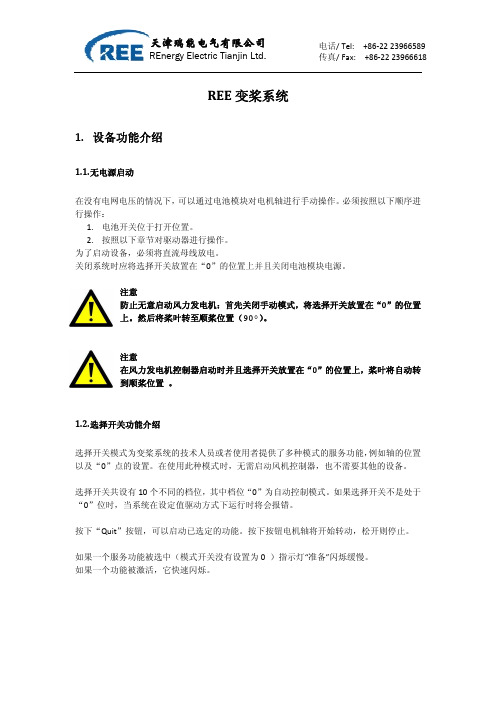
按下“Quit”按钮,可以启动已选定的功能。按下按钮电机轴将开始转动,松开则停止。
如果一个服务功能被选中(模式开关没有设置为 0 )指示灯“准备”闪烁缓慢。 如果一个功能被激活,它快速闪烁。
天津瑞能电气有限公司
REnergy Electric Tianjin Ltd.
REE 变桨系统
电话/ Tel: +86‐22 23966589 传真/ Fax: +86‐22 23966618
1.2. 选择开关功能介绍
选择开关模式为变桨系统的技术人员或者使用者提供了多种模式的服务功能,例如轴的位置 以及“0”点的关共设有 10 个不同的档位,其中档位“0”为自动控制模式。如果选择开关不是处于 “0”位时,当系统在设定值驱动方式下运行时将会报错。
天津瑞能电气有限公司
REnergy Electric Tianjin Ltd.
REE 变桨系统
电话/ Tel: +86‐22 23966589 传真/ Fax: +86‐22 23966618
1. 设备功能介绍
1.1. 无电源启动
在没有电网电压的情况下,可以通过电池模块对电机轴进行手动操作。必须按照以下顺序进 行操作:
选择开关位置
功能
自动控制模式:使用 PMM 中的控制模式 注意:在激活控制模式后电机轴将在起始位置与顺桨位置 之间自动运行。
正向手动驱动:按下“Quit”按钮,电机轴将向正向位置 转动。开始的两秒内转动速度较慢,之后快速转动。放开 按钮转动停止。
反向手动驱动:按下“Quit”按钮,电机轴将向反向位置 转动。开始的两秒内转动速度较慢,之后快速转动。放开 按钮转动停止。
- 1、下载文档前请自行甄别文档内容的完整性,平台不提供额外的编辑、内容补充、找答案等附加服务。
- 2、"仅部分预览"的文档,不可在线预览部分如存在完整性等问题,可反馈申请退款(可完整预览的文档不适用该条件!)。
- 3、如文档侵犯您的权益,请联系客服反馈,我们会尽快为您处理(人工客服工作时间:9:00-18:30)。
版本:V1.0
REE-OAT变桨系统现场调试手册
发布日期:2009年9月9日
REE-OAT变桨系统现场调试手册
本文件用于指导1.5MW(低温型)风机用变桨系统的现场调试,变桨系统的调试要严格按照调试步骤进行,做好调试记录。
一、调试工具
●调试软件Windbench;
●笔记本电脑一台;
●万用表一个;
●工具箱一个:配有一字型、十字型螺丝刀、一套内六角扳手和尖嘴钳等
工具;
●REE-OAT变桨系统原理图一份;
二、上电前的常规检查
●确认变桨系统各部件间的电缆连接正确,且各航空插头连接牢靠;
●检查各控制箱内及箱外的元器件是否完好无损;
●确认各控制箱和电池箱的电源开关均处于断开状态,箱内的电路保护开
关均处于断开状态;
●电池电压在满电状态应为246V,如低于241V,电池已处于充电状态,
此时充电激活以及充电电流项的指示灯应为绿色,电池电流值为负值。
充电器激活
注意:系统上电前一定要确保三相400V电压正常和相序正确,N线和PE接地线连接正确且固定牢靠,电源不能缺项,否则容易造成模块烧毁。
三、单独调试步骤
1.首先一定要先合上三个电池箱的开关1Q2,2Q2,3Q2;
2.PC调试步骤(按照以下示意图分步完成):
●检查Q1(400V AC)进线端电压是否正常,出线端是否对地短路,正常
则合上Q1;
●检查S1(230V AC)进线端电压是否正常,出线端是否对地短路,正常
则合上S1,检查照明灯是否正常;
●检查Q11,Q21,Q31(400V AC)进线端是否正常,出线端是否对地短
路,正常则合上Q11,Q21,Q31;
●检查F11,F21,F31(230V AC)进线端是否正常,出线端是否对地短路,
正常则合上F11,F21,F31;
●接通电源,打开Windbench软件并选择通讯接口并且打开测试软件
,
●PMM测试
☞接通电源,打开Windbench软件并选择通讯接口
☞点击ok确定。
☞
检测通讯是否正常。
通讯接口计算机端与设备端指示灯均为绿色。
☞
根据自身需要选择登录权限
用户—>登录 —>选择权限3—>输入密码(OAT300)
点击【功能】选择设备
在设备栏中分别选择各个桨叶中的PMM 的test 子目录,检查其中的每个参
数。
(如变桨设备长时间未通电,应着重关注电池状态)
电池电压在满电状态应为246V ,如低于241V ,电池已处于充电状态,此时充电激活以及充电电流项的指示灯应为绿色,电池电流值为负值。
如发现异常项目,则该项目所对应的设备或元件故障。
● 参数设定
☞
设置重要电机参数,以符合客户要求。
在修改参数前应注意首先点进start 读取参数,之后stop 。
电机参数设置应在每个轴箱的PMC->parameter 中修改。
(如明阳)修改6091中的1为26549,6091中的2为15,687e 改为192,6891中1为139,6891中2为11.
每次修改参数后点击回车,使修改的参数得以保存。
在修改过后电机参数后点击save apply 。
之后重新读取。
关闭中控箱后45S ,重新上电,再次读取数据以确定参数修改成功。
“0”点设置和PMC 测试
☞
调整轮毂桨叶轴承至0位,通过手动控制设置0位。
☞
在设备栏中分别选择各个桨叶中的PMC 的test 子目录,选择“运动方式”,分别对每个功能进行电机测试。
如发现异常状态,检测相应的设备或元件。
● “91°”限位开关测试
电机将在PMC 的控制下转动,桨叶向90°转动。
当限位开关被按下时,电机停止转动。
当松开限位开关时,电机继续转动,至90°时停止。
☞
点击“开始”或者快捷键F6
☞ 选择各个桨叶中的PMC 的test 子目录,选择“运动方式”为位置1,将位置1设为90°
☞
在电机转动过程中拨动91° 的限位开关。
☞
选择各个桨叶中的PMC 的test 子目录,选择“运动方式”为位置1,将位置1设为0°
☞
点击“开始”或者快捷键F6
当限位开关被按下时,电机继续转动,直至桨叶达到0°位置时停止。
●“95°”限位开关测试
电机将在PMC的控制下转动,桨叶向90°转动。
当限位开关被按下时,电机停止转动,并且系统报错。
当松开限位开关时,
电机不再继续转动,此时应按“Reset”键或“F10”复位,再次点击“开
始”或者快捷键F6,桨叶继续转动至90°时停止。
☞在电机转动过程中拨动91°的限位开关。
☞选择各个桨叶中的PMC的test子目录,选择“运动方式”为位置1,将位置1设为90°
☞点击“开始”或者快捷键F6
☞在电机转动过程中拨动95°的限位开关。
当限位开关被按下时,电机停止转动,并且系统报错。
当松开限位开关时,电机不再继续转动,此时应按“Reset ”键或“F10”复位,再次点击“开始”或者快捷键F6,桨叶继续转动至0°时停止。
● 测试加热器功能
加热器的温度参数设置应在每个轴箱的PMM->parameter 中修改。
修改3201中的1为500,
中控箱加热器的温度参数设置应在3号轴箱的PMM->parameter 中修改。
修改3203中的1为500,点击回车。
在修改参数前应注意首先点进start 读取参数,之后stop 。
☞
选择各个桨叶中的PMC 的test 子目录,选择“运动方式”为位置1,将位
置1设为0°。
☞
点击“开始”或者快捷键F6
☞
在电机转动过程中拨动95°的限位开关。
☞
将加热器的工作温度参数从0°C 修改为50°C 使其开始工作。
在确认加热器可以正常工作时,将参数修改回初始值(0°C ),使加热器
关闭。
● 测试电机散热风扇
点击PMM->parameter 后,打开参数页。
点击Editor 或者快捷键F2,打开FrmparameterEditor 窗口,点击左上角的Load EDS-File 按钮,打开EDS 中的PMM01 文件。
此时在Load EDS-File 按钮下方的空白处将出现3个objects 选项,点开第3个objects (Manufacturerobjects ),在其中找到参数3204。
单击3204,在其右侧的表格中将出现4个参数。
选择中3204(1)后,点击其下方的Add selecter items 按钮,此时参数3204(1)已加入参数列表。
关闭FrmparameterEditor 窗口。
电机散热风扇的温度参数设置应在每个轴箱的PMM->parameter 中修改。
修改3204中的1的800为0。
☞
在每个轴箱中的PMM->parameter 中添加参数3204(1)。
☞
将电机散热风扇的工作温度参数从80°C 修改为0°C 使其开始工作。
在确认电机散热风扇可以正常工作时,将参数修改回初始值(80°C),使电机散热风扇关闭。