AP-10说明书
转速器盘设计说明书

机械制造工艺学课程设计任务书题目:转速器盘零件的机械加工工艺规程及专用夹具内容:(1)零件一毛坯合图1张(2)机械加工工艺规程卡片12张(3)夹具装配总图1张(4)夹具零件图一张(5)课程设计说明书一份原始资料:该零件图样一张;单件大批量生产。
班级:12机制1班学生:陈再好2015年12月28 日目录第一部分:序言 (2)一设计目的 (2)二设计感想与体会 (2)第二部分:工艺规程与夹具设计过程工艺规程与夹具设计过程 (4)一、设计题目,计算生产纲领及生产型 (4)二、零件的分析 (5)(一)零件的作 (5)(二)零件的工艺分析 (5)三、确定毛坯的制造方法,初步确定毛坯 (6)四、工艺规程设计 (6)(一) 定位基准的选择 (6)(二)零件表面加工方法的选择 (7)(三)制定加工工艺路线 (8)(四)选择加工设备及刀、夹、量具 (10)五、加工工序设计 (11)(一)确定切削用量及基本工时…………………………………………11六、填写机械加工工艺卡和机械加工工序卡 (17)七、夹具设计 (17)(一)问题的提出 (17)(二)夹具设计的有关计算 (17)(三)夹具结构设计及操作简要说明 (20)八、主要参考文献 (21)序言一、设计目的:现代机械制造工艺设计是机械类专业学生在学完了《机械制造技术基础》等技术基础和专业课理论之后进行的一个实践教学环节。
其目的是巩固和加深理论教学内容,培养学生综合运用所学理论,解决现代实际工艺设计问题的能力。
通过工艺规程及工艺装备设计,学生应达到:1、掌握零件机械加工工艺规程设计的能力;2、掌握加工方法及其机床、刀具及切削用量等的选择应用能力;3、掌握机床专用夹具等工艺装备的设计能力;4、学会使用、查阅各种设计资料、手册和国家标准等,以及学会绘制工序图、夹具总装图,标注必要的技术条件等。
二、设计感想与体会:三周的课程设计就是一个团队合作的过程.所谓1+1〉2,一个团队的合作,使我们的设计成果不到三周时间就渐渐呈现在我们的眼前.看着眼前的手工图纸、CAD图和设计计算的手稿,三周的设计过程一幕幕浮现在眼前.三周的设计让我们学到了很多东西。
对讲机几种常见业余机简介
几种常见业余机简介前一段时间提到了器材的问题,现在这里,将我用过的或听说过的机器的性能做一个简单的介绍,供大家参考。
1、TM-231A、241A 同属八十年代末的产品,纯业余机,当初由于专业机较少,因此各单位买回后经锁频当专业机用,设有频率模式和信道模式,频率在136-174可调,最大射频输出50W,21信道,使用方便,收发性能好,小巧轻便(1KG),但稳定性一般,尤其不禁摔,不过适合业余用,是一款较好的机器。
241的功能较231多一些,不过无关痛痒;2、TM-231S与前两款机器主要性能完全一样,但是多了118-136的航空调幅频段,而且使用的是黑底亮字彩色液晶屏,视觉感觉较前两种机器漂亮。
但这种机器好像不多见。
此机型值得推荐;3、TM-431A、441A是TM-231A、241A的姊妹机。
400MHZ频段,进口时以高低段居多,430-440比较少见,使用前应调整收发回路。
调整后435灵敏度不错,也可兼顾450频段,但灵敏度有所降低;4、IC-28A,主要功能、性能、年代与231大同小异,抗干扰能力较231/241好些;5、TK-708、708H属于八十年代末的半专业机,频率在136-170可调,25/50W,但必须在信道状态下工作,须在设定模式下手置频,因此使用上就上述机器有些不方便,16信道,收发性能较好,小巧轻便,稳定性一般,也较适合业余使用。
但有高低段之分,以低段机为宜,因为它涵盖业余段,无需再调整了;6、TK-808、808H是708的姊妹机,400MHz 分高低段,25/45W,使用前须调整收发槽路,主观感觉调整后435MHZ灵敏度尚可;7、GX3000属于八十年代中后期的专业机,日本驰电达产品,性能稳定,结构坚固,抗干扰能力较好,故障率低,个头较其它机器大,有大将风范,EPROM写频,收发性能好。
但使用上不如前两种机器方便,频率需事先写入,不能随便跑,频道数64个;8、C460是九十年代初的产品,外形与C450相近,但小巧玲珑,给人爱不释手的感觉,功能多,收发性能好,结构紧密,省电,在同年代产品中属于出类拔萃的,尤其称道的是其原装天线,虽增益极差,但是外观精致,很是不错。
TL-XAP3007GC-PoE DC易展版双频WiFi 6无线易展AP用户手册说明书

双频W i F i6无线易展A P用户手册REV1.0.01910041073声明Copyright © 2022 普联技术有限公司版权所有,保留所有权利未经普联技术有限公司明确书面许可,任何单位或个人不得擅自仿制、复制、誊抄或转译本手册部分或全部内容,且不得以营利为目的进行任何方式(电子、影印、录制等)的传播。
为普联技术有限公司注册商标。
本手册提及的所有商标,由各自所有人拥有。
本手册所提到的产品规格和资讯仅供参考,如有内容更新,恕不另行通知。
除非有特殊约定,本手册仅作为使用指导,所作陈述均不构成任何形式的担保。
前言本手册旨在帮助您正确使用AP产品。
内容包含对AP产品性能特征的描述以及配置AP产品的详细说明。
请在操作前仔细阅读本手册。
目标读者本手册的目标读者为熟悉网络基础知识、了解网络术语的技术人员。
本书约定其他约定在本手册中,所提到的“AP”、“本产品”等名词,如无特别说明,系指双频WiFi 6无线易展AP产品。
全文如无特殊说明,Web界面以TL-XAP3007GC-PoE/DC易展版机型为例。
本文介绍双频WiFi 6无线易展AP产品通用性配置,具体配置项目请以实际机型为准。
目录1 登录 ................................................................................................................................................1-1 1.1 登录Web管理界面 ......................................................................................................................1-11.1.1 需求介绍 ...........................................................................................................................1-11.1.2 设置方法 ...........................................................................................................................1-1 1.2 FAT模式下连云设置方法 .............................................................................................................1-41.2.1 商云APP扫码添加设备上云 ............................................................................................1-51.2.2 商云APP通过设备的ID/MAC添加设备上云 ..................................................................1-71.2.3 商云APP无线添加设备上云 ..........................................................................................1-101.2.4 商用网络云平台通过设备的ID添加设备上云 ...............................................................1-12 1.3 基础连网设置 .............................................................................................................................1-141.3.1 DHCP动态获取IP上网 .................................................................................................1-141.3.2 配置静态IP上网 ............................................................................................................1-162 工作模式 .........................................................................................................................................2-1 2.1 FAT AP模式 .................................................................................................................................2-12.1.1 设备信息 ...........................................................................................................................2-22.1.2 无线参数 ...........................................................................................................................2-22.1.3 扫码上云 ...........................................................................................................................2-32.1.4 易展设备列表 ...................................................................................................................2-42.1.5 无线服务 ...........................................................................................................................2-42.1.6 无线客户端 .......................................................................................................................2-5 2.2 FIT AP模式 ...................................................................................................................................2-5 2.3 易展组网 .......................................................................................................................................2-52.3.1 易展AP .............................................................................................................................2-52.3.2 AP模式 .............................................................................................................................2-62.3.3 Router模式 ......................................................................................................................2-83 无线 ................................................................................................................................................3-13.2.1 扫描选择 ...........................................................................................................................3-63.2.2 手动设置 ...........................................................................................................................3-7 3.3 高级设置 .......................................................................................................................................3-8 3.4 FAT模式下弱信号限制和弱信号剔除配置指南 ...........................................................................3-93.4.1 应用介绍 ...........................................................................................................................3-93.4.2 需求介绍 ...........................................................................................................................3-93.4.3 设置方法 .........................................................................................................................3-10 3.5 FAT模式下多个SSID配置指南 .................................................................................................3-103.5.1 应用介绍 .........................................................................................................................3-103.5.2 需求介绍 .........................................................................................................................3-103.5.3 设置方法 .........................................................................................................................3-114 安全 ................................................................................................................................................4-1 4.1 无线MAC地址过滤 ......................................................................................................................4-1 4.2 VLAN设置 ....................................................................................................................................4-2 4.3 FAT模式下MAC地址过滤配置指南 ............................................................................................4-34.3.1 应用介绍 ...........................................................................................................................4-34.3.2 需求介绍 ...........................................................................................................................4-34.3.3 设置方法 ...........................................................................................................................4-35 系统 ................................................................................................................................................5-1 5.1 工作模式 .......................................................................................................................................5-2 5.2 云管理 ..........................................................................................................................................5-25.2.1 TP-LINK本地NMS管理平台 ...........................................................................................5-25.2.2 TP-LINK商用网络云平台 .................................................................................................5-3 5.3 设备管理 .......................................................................................................................................5-45.3.1 IPv4 ..................................................................................................................................5-45.3.2 IPv6 ..................................................................................................................................5-5 5.4 管理账号 .......................................................................................................................................5-65.7 配置管理 .......................................................................................................................................5-8 5.8 在线软件升级 ...............................................................................................................................5-8 5.9 软件升级 .......................................................................................................................................5-9 5.10 Ping看门狗 ..................................................................................................................................5-9 5.11 FAT模式下Ping看门狗配置指南 ..............................................................................................5-10 5.11.1 应用介绍 .........................................................................................................................5-10 5.11.2 需求介绍 .........................................................................................................................5-10 5.11.3 设置方法 .........................................................................................................................5-10 5.11.4 配置注意事项 .................................................................................................................5-121 登录双频WiFi 6无线易展AP用户手册双频WiFi 6无线易展AP支持两种工作模式:FAT AP模式和FIT AP模式。
优科无线AP 设置
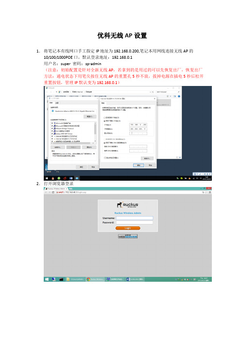
优科无线AP设置1.将笔记本有线网口手工指定IP地址为192.168.0.200,笔记本用网线连接无线AP的10/100/1000POE口,默认登录地址:192.168.0.1用户名:super 密码:sp-admin(注意:初始配置是针对全新无线AP,若拿到的是用过的可以先恢复出厂,恢复出厂方法:通电状态下用笔尖按住无线AP的重置孔5秒不放,拔掉电源在插电5秒后松开重置按钮,管理IP默认变为192.168.0.1)2.打开浏览器登录3.更改默认登录密码:4.指定DNS,此步骤可以默认即可6.开启DHCP功能5.修改列表中2.4G信息注意:若教室周围有较强的2.4G信号,可以在平板上安装“wifi概观360”软件扫描下周围的无线信号所占用的Channel,然后将我们的设备和周围的Channel错开,2.4G信号Channel选择1、6、11相互间干扰最小。
8.添加2.4G学生信号ChangyanSTU,设置ssid及密码9.修改5G 显示信息Channel可以修改为149-169之间的可选频段(注意:畅言智慧课堂对5G无线信号名称要求为ChangyanTCH开头,密码iFlytek1234)下图的标签位置可以查看5G状态,若为UP状态平板搜不到5G信号(不是所有平板和手机都支持5G操作前可以网上查看配置是否支持5G)可以更改Channel153、157、161测试,也可以把上图的Wireless Availability 先Disabled ,保存后,再点击一次Enabled,保存退出,看是否能搜到信号。
10此处按下图配置port1为外网口,port2设置为云服务器连接口。
(注意:靠近电源口的网口为PORT1,若按下图配置后,切勿将外网线插入PORT2,以免造成学校网络中断)常见故障和其它配置其它设置:1.后期可通过无线登录管理界面打开浏览器输入https://192.168.40.1,出现登录画面输入用户名super,密码sp-admin2.指定外网口IP地址上网按下图设置,进入AP管理界面,选择左侧configuration->Internet,输入的IP地址和DNS为现场网管提供。
CMK系列使用说明书
-3-
2 安全注意事項
運轉
• 停電時,請切斷驅動器的電源,否則恢復供電後馬達突然起動,有可能導致 人員受傷或造成裝置損壞。
• 馬達運轉中,請勿將 AWO(輸出電流 OFF)輸入設定在 ON 上,否則馬達 會停止,失去保持力,有可能導致人員受傷或造成裝置損壞。
修理‧拆解‧改造
• 請勿對馬達、驅動器進行拆解或改造,否則有可能導致人員受傷。需要對內 部進行檢查或修理時,請與台灣東方馬達股份有限公司聯繫。
整體
• 使用馬達、驅動器時,請勿超過其規格值,否則有可能導致人員受傷或造成 裝置損壞。
• 馬達、驅動器的開口部中請勿伸進手指或插入物體,否則有可能引起火災或 導致人員受傷。
• 運轉中或停止後一段時間內,請勿碰觸馬達和驅動器,否則有可能因馬達表 面和驅動器的高溫而引起燙傷。
• 請勿強行彎曲、拉扯連接於驅動器的電源電纜線及馬達電纜線,否則會增加 驅動器的應力,可能導致損壞。
組合製品名 CMK223SG
CMK243SG CMK264SG
減速比
運轉方向
1:7.2、1:36
ቤተ መጻሕፍቲ ባይዱ
與馬達軸同方向
1:9、1:10、1:18 與馬達軸反方向
1:3.6、1:7.2、1:9、 1:10、1:50、1:100
與馬達軸同方向
1:18、1:36
與馬達軸反方向
減速機型馬達的潤滑油
減速機型馬達偶爾會滲出少量的潤滑油。若潤滑油的滲漏給周圍環境帶來污染 問題,請在定期檢查時檢查是否有潤滑油的滲漏。另外,請安裝油脂回收器等 防止損害的裝置,否則可能會因漏油而損害裝置或使製品等運轉不正常。
5 設 置 .......................................... 12
普联TP-LINK 室外无线 AP TL-AP302P 安装手册

当用户需要组建的无线网络规模较小时,可以使用 FAT AP 模式, 此模式下,AP 支持 Web 界面管理,用户可以登录 AP 的 Web 管 理界面进行无线功能设置,管理网络中的无线客户端,设置 AP 的 网络参数等。
登录 AP Web 界面的方法,请参考本手册登录 FAT AP 管理界面。
复位键。复位操作为:在AP通电的情况下,长按RESET 键,待系统指示灯闪烁4次后松开RESET键,AP将自动 恢复出厂设置并重启。重启完成后,系统指示灯会常 亮,表示系统开始正常工作。
03
Passive PoE 供电器面板介绍 :
DC
POE LAN
直流电源接口 PoE供电口 RJ45口
04
典型应用拓扑
1 个 10/100M RJ45 接口
按钮
1 个 RESET 按钮 +1 个 FIT/FAT 模式拨动开关
指示灯
1 个 SYS 指示灯
供电方式
9VDC 0.85A 电源适配器供电 /9V Passive PoE 供电
使用环境
工作温度:-30℃~ 65℃;工作湿度:10% ~ 90%RH 不凝结 存储温度:-40℃~ 70℃;存储湿度:5% ~ 90%RH 不凝结
13
软件规格
FAT AP 模式
SSID 广播
支持
中文 SSID
支持
网络类型
访客网络、员工网络
无线加密 无线 用户隔离 安全
VLAN 设置 无线 功能 信道
发射功率设置
WPA、WPA2、WPA-PSK、WPA2-PSK 无线网络间隔离、无线网络内部隔离 支持 SSID 和 Tag VLAN 绑定 支持自动调节与手动设定 支持 1dBm 线性调节
MB1-10AP 用户手册说明书
User ManualV1.4 M aster Series Embedded SystemIntel ® Apollo Lake ProcessorsEfficient, Versatile, and Rugged & ReliablePREFACECopyright NoticeCopyright © 2016-2020 MiTAC Computing Technology Corporation (MiTAC Group). No part of this document may be reproduced, copied, translated, or transmitted in any form or by any means, electronic or mechanical, for any purpose, without the prior written permission of MiTAC Corp., Ltd. All information and specification provided in this manual are for reference only and remain subject to change without prior notice.DisclaimerWe reserve the right to make changes, without notice, to any product, including circuits and/or software described or contained in this manual in order to improve design and/or performance. We assume no responsibility or liability for the use of the described product(s) conveys no license or title under any patent, copyright, or masks work rights to these products, and make no representations or warranties that these products are free from patent, copyright, or mask work right infringement, unless otherwise specified. Applications that are described in this manual are for illustration purposes only. We make no representation or guarantee that such application will be suitable for the specified use without further testing or modification.Declaration of ConformitySafety InformationSafety PrecautionsFor your safety, please carefully read all the safety instructions before using the device. All cautions and warnings on the equipment should be noted. Keep this user manual for future reference.*Let service personnel to check the equipment in case any of the following problems appear:⏹The power cord or plug is damaged.⏹Liquid has penetrated into the equipment.⏹The equipment has been exposed to moisture.⏹The equipment does not work well or you cannot get it to work according to the user manual.⏹The equipment has been dropped and damaged.⏹The equipment has obvious signs of breakage on the surface.Ordering InformationPacking ListOptional Xpansion Modules MS-01DVI-D10MS-01DPN-D10MS-02COM-D10MS-08DIO-T10CONTENTSPREFACE (2)CHAPTER 1: INTRODUCTION (8)1.1 Overview (8)1.2 Product Features (8)1.3 Hardware Specification (9)1.4 Mechanical Specification (12)1.5 System I/O Placement (13)CHAPTER 2: DIP SWITCH SETTING AND PIN DEFINITION (16)2.1 DIP Switch and Connector Overall Placement (16)2.2 DIP Switch Setting (18)2.3 Connector Pin Definition (19)CHAPTER 3: SYSTEM SETUP (26)3.1 2.5” SATA HDD/SSD Installation (26)3.2 WiFi module Installation (27)3.3 DRAM Installation (28)CHAPTER 4: BIOS SETUP (31)4.1 Main Page (31)4.2 Advance Page (33)4.3 Security Page (42)4.4 Boot Page (46)4.5 Save & Exit Page (47)INTRODUCTIONThis chapter provides the MB1-10AP EmbeddedSystem product overview, including features, hardware and mechanical specifications. 1CHAPTER 1: INTRODUCTIONThis chapter provides the MB1-10AP Embedded System product overview, including features, hardware, mechanical specifications, and I/O placement.1.1 OverviewMiTAC’s MB1-10AP embedded system is the next generation embedded system with Intel® Apollo Lake embedded processor. The efficient performance, OCP/OVP power protection, and expandable design provide the solution for routine tasks and most types of application.1.2 Product FeaturesMB1-10AP Embedded System offers the following features:⏹Intel® Apollo Lake-M N3350/N4200 Processors⏹Support 2 x PoE LAN (Optional)⏹Support HDMI as primary display, and VGA/DisplayPort/DVI-D as second option⏹Fan-less chassis and Expandable module design⏹Support COM/DIO via Xpansion Modules⏹8-24V Wide Power Voltage⏹-25°C to 70°C (For non-PoE SKU, with 0.7m/s Air Flow and Wide TemperatureMemory/Storage)-25°C to 60°C (For PoE SKU, with 0.7m/s Air Flow and Wide TemperatureMemory/Storage)1.3 Hardware Specification*Notes1: Installation in Restricted Access Location (RAL)A restricted access location is a designated area within an incident area (High or Low temperature environment)With authorized people can enter for a period of time and for a specific purpose.1.Access can only be gained by service people or by users who have beeninstructed about the reasons for the Restrictions applied to the location and about any precautions that shall be taken.2.Access is through the use of a tool or lock and key, or other means ofsecurity, and is controlled by the authority Responsible for the location.*Notes2: Please make sure that the power consumption is in the spec of the power supply output capability from AC adaptor (72W or 120W). Please choose the suitable AC adaptor for your application.AC/DC 24V/5A, 120W 3PIN Terminal Block Power Adaptor (For PoE SKU)AC/DC 24V/3A, 72W 3PIN Terminal Block Power Adaptor (For non-PoE SKU)*Note3: Please choose 120W AC adaptor for the Optional Xpansion Module (MS-02COM-D10) COM ports in maximum power loading scenario (12V max. 1A loading).*Note4: Please don’t load the COM power in the hardware configuration and high temperature condition. Don’t operate the machine at maximum operating temperature 70℃(Non-PoE SKU) & 60℃(PoE SKU) with 4*COM 12V*1A loading.*Note 5: The maximum ambient operating temperature is 40°C if the external AC adapter model: EA11011M or EA10681V will be placed in thesame high temperature area with the embedded system.*Note 6: CAUTION - Lithium battery is included in this embedded system. Please do not puncture, mutilate, or dispose of battery in fire. There will be danger of explosion if battery is incorrectly replaced. Replace only with the same or equivalent type recommended by manufacturer. Dispose of used battery according to manufacturer instructions and in accordance with your local regulations.*Note 7: CAUTION - Only allow technically qualified personnel to touch the I/O surface, and only when the unit is well fastened by wall mount, VESA mount, or DIN Rail mount. Please also avoid to contact the I/O surface more than 1 second in high temperature and harsh environment. Not allow to touch aluminum alloy surface at high temperature. The technically qualified personnel also needs to have technical knowledge, operating experiences, and basic knowledge about MB1-10AP product spec.1.4 Mechanical SpecificationMechanical Dimension: 170 mm x 105 mm x 57 mm1.5 System I/O Placement⏹Front I/O:⏹Rear I/O:Xpansion Module (Optional) ConfigurationDIP SWITCH SETTING AND PIN DEFINITIONThis chapter provides information about how to set up thedip switch and use I/Os of MB1-10AP Embedded System hardware. 2CHAPTER 2: DIP SWITCH SETTING AND PIN DEFINITIONThis chapter provides information about how to set up the dip switch, and use internal I/Os of MB1-10AP Embedded System hardware.2.1 DIP Switch and Connector Overall PlacementFront View:Bottom View:2.2 DIP Switch Setting⏹Location #B6ATATX A SW_ATX1CAdd this table in silkscreen TXTDefault ATX mode⏹ Location #B7/B8/B9/B102.3 Connector Pin Definition⏹ Indicator for Realtek RTL8154B LAN⏹ Location #B4 – SATA and SATA PWR Connector3-pin terminal block for DC Input⏹2-pin Remote Power On/Off HeaderMB Side Connector: Molex 151064-0152Suggestive Cable Side Plug: Molex 151100-0002⏹COM1 and COM2 on M/BMB COM1 and COM2 RS232, RS422, RS485 setting is at BIOS setup menuMS-02COM-D10 (Optional)Xpansion Module with 2 x RS232/422/485 (Non-isolation)Support 5V/12V DC Power OutputNotes: Don't support Power HOT switch at SW_PW3 and SW_PW4 in Xpansion Module Below is Xpansion Module with COM3 and COM4: See the power RS232 setting as below table:Default setting is RI signal at A location from SW_RI3 and SW_RI4Power COM setting with RI signal: Default settingSET at A location from SW_RI3 and SW_RI4SET at A location from SW_PW3 and SW_PW4Power 5V setting:SET at C location from SW_RI3 and SW_RI4 SET at A location from SW_PW3 and SW_PW4Power 12V setting:SET at C location from SW_RI3 and SW_RI4 SET at C location from SW_PW3 and SW_PW4Power 12V setting: Change at C location from SW_RI3 and SW_RI4 and at C location from SW_PW3 and SW_PW4MS-08DIO-T10 (Optional)Xpansion Module with 8-bit Optical Isolation DIDO (4 x DI, 4 x DO)SYSTEM SETUPThis chapter provides information about how to set up the MB1-10AP Embedded System hardware installation. 3CHAPTER 3: SYSTEM SETUPThis chapter provides information about how to set up the MB1-10AP Embedded System hardware installation.3.1 2.5” SATA HDD/SSD InstallationPlease follow the instructions to install SATA HDD as below. - Loosen 6 screws from Bottom cover as the arrow locations- Loosen 4 screws as the arrow directions-Move HDD tray as arrow direction-Lift HDD tray about 45 degrees and draw it out-Install 2.5”HDD to the HDD tray3.2 WiFi module Installation-Use mPCIe extension bracket which is in accessories kit to fix half size mPCIe wifi module, and install to the full size mPCIe slot3.3 DRAM Installation-Loosen 4 screws from MB (2 screws from front & rear cover)-Draw the MB sub-assembly out from top cover as arrow direction-Remove the film from top cover & install DIMM to MBBIOS SETUPThis chapter provides information about how to set up BIOS and use BIOS menu items to adjust basic function settings. 4CHAPTER 4: BIOS SETUPThis chapter provides information about how to set up BIOS and use BIOS menu items to adjust basic function settings.4.1 Main Page4.2 Advance Page4.2.1 Intel(R) I210 Gigabit Network Connection4.2.2 Trusted Computing4.2.3 NCT6116D Super IO Configuration4.2.4 Hardware Monitor4.2.5 S5 RTC Wake Setting4.2.6 CPU Configuration4.3 Security Page4.3.1 Secure Boot4.3.2 BIOS Update4.4 Boot Page4.5 Save & Exit Page。
TS-AP10 室内型AP产品手册
产品手册
北京东方信联无线通信有限公司 2010 年 4 月
前 言 手册说明
本文档用于介绍 TS-AP10 室内型 AP 的外观、型号、规格,并指导您如何正确安装本产 品。请先阅读本文档,再进行操作。
目标读者
本文档的目标读者为合作伙伴、代理商的技术支持人员及工程安装调试人员 。
高级操作..................................................................................................................... 20 3.3.1 3.3.2 3.3.3 3.3.4 3.3.5 3.3.6 无线设备高级配置 ......................................................................................... 20 VLAN 配置..................................................................................................... 21 ACL 配置 ........................................................................................................ 21 以太网口配置 ................................................................................................. 22 流量控制配置 ................................................................................................. 22 版本更新 ......................................................................................................... 23
华为 AP6750-10T 无线访问点数据手册说明书
Huawei AP6750-10T Access Point DatasheetProduct OverviewHuawei AP6750-10T is an access point (AP) that supports 802.11ac Wave 2, has built-in adaptive array antennas, and provides triple radios: one 2.4 GHz radio and two 5 GHz radios. The 2.4 GHz radio supports 2x2 MIMO and two spatial streams, one 5 GHz radio supports 2x2 MIMO and two spatial streams, and the other 5 GHz radio supports 4x4 MIMO and four spatial streams. AP6750-10T complies with 802.11n, 802.11ac, and 802.11ac Wave 2, outperforms other APs in network compatibility, and provides optimal wireless network experience for users. With these features, AP6750-10T best adapts to high-density scenarios such as e-classrooms and supermarkets.AP6750-10T●Provides services simultaneously on one 2.4 GHz radio and two 5 GHz radios, at a rate of 3 Gbit/s for the entire device. The 2.4 GHz radio supports 2x2 MIMO, providing a maximum rate of 400 Mbit/s. One 5 GHz radio supports 2x2 MIMO, and the other 5 GHz radio supports 4x4 MIMO, providing a maximum rate of 867 Mbit/s and 1733 Mbit/s, respectively.●Uses adaptive array antenna technology to enable targeted signal coverage for mobile terminals and improve signal quality. Additionally, this technology implements switchover as STAs move.●Supports Bluetooth serial interface-based O&M through built-in Bluetooth and CloudCampus APP, and precise locating of Bluetooth terminals and tags by collaborating with the location server.●Provides a USB interface for external power supply and storage. An IoT module can also be installed on the USB interface to implement flexible IoT application extension.●Supports the Fat, Fit, and cloud modes and enables Huawei cloud management platform to manage and operate APs and services on the APs, reducing network O&M costs.Feature DescriptionsTriple-radio designThe AP has triple radios: one 2.4 GHz radio and two 5GHz radios. When all the triple radios work, the device rate can reach 3 Gbit/s.Adaptive array antennas (smart antennas)The AP integrates adaptive array antennas (smart antennas) and implicit beamforming to implement more precise user detection, suppress interference, and improve signal quality, bringing seamless and smooth wireless network experience at the users' fingertips.Cloud-based managementHuawei Cloud Managed Network (CMN) Solution consists of the cloud management platform and a full range of cloud managed network devices. The cloud management platform provides various functions including management of APs, tenants, applications, and licenses, network planning and optimization, device monitoring, network service configuration, and value- added services.High Density Boost technologyHuawei uses the following technologies to address challenges in high-density scenarios, including access problems, data congestion, and poor roaming experience:SmartRadio for air interface optimization●Load balancing during smart roaming: The load balancing algorithm can work during smart roaming, enabling load balancing detection between APs on the network after STA roaming to adjust the STA load on each AP, improving network stability.●Intelligent Dynamic Frequency Assignment (DFA) technology: The DFA algorithm is used to automatically detect adjacent-channel and co-channel interference, and identify any redundant 2.4 GHz radio. Through automatic inter-AP negotiation, a redundant radio is automatically switched to another mode (dual-5G AP models support 2.4G-to-5G switchover) or is disabled to reduce 2.4 GHz co-channel interference and increase the system capacity.●Intelligent conflict optimization technology: Dynamic enhanced distributed channel access (EDCA) and airtime scheduling algorithms are used to schedule the channel occupation time and service priority of each STA. This ensures that each STA is assigned a relatively equal amount of time for using channel resources and user services are scheduled in an orderly manner, improving service processing efficiency and user experience.Air interface performance optimization●In high-density scenarios where many STAs access the network, an increased number of low-rate STAs consume more resources on the air interface, reduce the AP capacity, and lower user experience. Therefore, Huawei APs will check the signal strength of STAs during access and reject access from weak-signal STAs. At the same time, the APs monitor the rate of online STAs in real time and forcibly disconnect low-rate STAs so that the STAs can reassociate with APs that have stronger signals. Terminal access control technology can increase air interface use efficiency and allow access of more STAs.5GHz-prior access●The AP supports both 2.4G and 5G frequency bands. The 5G-prior access function enables an AP to steer STAs to the 5 GHz frequency band first, which reduces load and interference on the 2.4 GHz frequency band, improving user experience.Automatic radio calibration●Automatic radio calibration allows an AP to collect signal strength and channel parameters of surrounding APs and generate AP topology according to the collected data. Based on interference from authorized APs, rogue APs, and non-Wi-Fi interference sources, each AP automatically adjusts its transmit power and working channel to make the network operate at the optimal performance. In this way, network reliability and user experience are improved.Wired and wireless dual security guaranteeTo ensure data security, Huawei APs integrate wired and wireless security measures and provide comprehensive security protection.Authentication and encryption for wireless access●Huawei APs support WEP, WPA/WPA2-PSK, WPA/WPA2-PPSK, WPA/WPA2-802.1X, and WAPI authentication/encryption modes to ensure security of a wireless network. The authentication mechanism is used to authenticate user identities so that only authorized users can access network resources. The encryption mechanism is used to encrypt data transmitted over wireless links to ensure that the data can only be received and parsed by expected users.Analysis on non-Wi-Fi interference sources●Huawei APs can analyze the spectrum of non-Wi Fi interference sources and identify them, including baby monitors, Bluetooth devices, digital cordless phones (on 2.4 GHz frequency band only), wireless audio transmitters (on both the 2.4 GHz and 5 GHz frequency bands), wireless game controllers, and microwave ovens. Coupled with Huawei eSight, the APs can accurately detect interference sources, and display the spectrum of them on eSight, enabling the administrator to remove the interference in a timely manner.Rogue device monitoring●Huawei APs support WIDS/WIPS, and can monitor, identify, defend against, counter, and perform refined management on rogue devices, providing security guarantees for air interface environment and wireless data transmission.Automatic application identificationHuawei APs support smart application control technology and can implement visualized management and control on Layer 4 to Layer 7 applications.Traffic identification●Coupled with Huawei ACs, the APs can identify over 6000 common applications in various office scenarios. Based on the identification results, policy control can be implemented on user services, including priority adjustment, scheduling, blocking, and rate limiting to ensure efficient bandwidth resource use and improve quality of key services.Traffic statistics collection●Traffic statistics of each application can be collected globally, by SSID, or by user, enabling the network administrator to know application use status on the network. The network administrator or operator can implement visualized control on service applications on smart terminals to enhance security and ensure effective bandwidth control.Basic SpecificationsFat/Fit AP modeWLAN features Compliance with IEEE 802.11a/b/g/n/ac/ac Wave 2Triple radios, eight spatial streams, providing a maximum rate of 3 Gbit/sMaximum ratio combining (MRC)Space-Time Block Coding (STBC)Cyclic Delay Diversity (CDD)/Cyclic Shift Diversity (CSD)BeamformingMU-MIMOLow Density Parity Check (LDPC)Maximum-Likelihood Detection (MLD)Frame aggregation, including A-MPDU (Tx/Rx) and A-MSDU (Tx/Rx)802.11 dynamic frequency selection (DFS)Short guard interval (GI) in 20 MHz, 40 MHz, and 80 MHz modesAutomatic and manual rate adjustmentWLAN channel management and channel rate adjustmentAutomatic channel scanning and interference avoidanceSeparate Service Set Identifier (SSID) hiding configuration for each AP, supporting Chinese SSIDsSignal Sustain Technology (SST)Unscheduled Automatic Power Save Delivery (U-APSD)Control and Provisioning of Wireless Access Points (CAPWAP) in Fit AP modeAutomatic login in Fit AP modeExtended Service Set (ESS) in Fit AP modeMesh networking in Fit AP modeMulti-user CACHotspot2.0Smart roaming based on 802.11k and 802.11v802.11r fast roaming (≤ 50 ms)WAN authentication escape between APs and WLAN ACs. In local forwarding mode, this featurekeeps existing STAs online and allows for the access of new STAs when APs are disconnectedfrom WLAN ACs, ensuring service continuity.Network features Compliance with IEEE 802.3abAuto-negotiation of the rate and duplex mode and automatic switchover between the MediaDependent Interface (MDI) and Media Dependent Interface Crossover (MDI-X)Compliance with IEEE 802.1QSSID-based VLAN assignmentVLAN trunk on uplink Ethernet portsManagement channel of the AP uplink port in tagged and untagged modeDHCP client, obtaining IP addresses through DHCPTunnel forwarding and direct forwarding of service dataSTA isolation in the same VLANAccess control list (ACL)Link Layer Discovery Protocol (LLDP)Uninterrupted service forwarding upon CAPWAP channel disconnection in Fit AP modeUnified authentication on the AC in Fit AP modeAC dual-link backup in Fit AP modeNetwork Address Translation (NAT) in Fat AP modeIPv6 in Fit AP modeIPv4/IPv6 ACLSoft Generic Routing Encapsulation (GRE)IPv6 Source Address Validation Improvements (SAVI)Multicast Domain Name Service (mDNS) gateway protocol: supports AirPlay and AirPrint servicesharing between users of different VLANsQoS features Priority mapping and packet scheduling that are compliant with Wi-Fi multimedia (WMM) toimplement priority-based data processing and forwardingWMM parameter management for each radioWMM power savingPriority mapping for upstream packets and flow-based mapping for downstream packetsQueue mapping and schedulingUser-based bandwidth limitingAdaptive bandwidth management (automatic bandwidth adjustment based on the user quantity andradio environment) to improve user experienceSmart Application Control (SAC) in Fit AP modeAirtime schedulingSupport for Microsoft Lync APIs and high voice call quality through Lync API identification andschedulingSecurity features Open system authenticationWEP authentication/encryption using a 64-bit, 128-bit, or 152-bit encryption keyWPA2-PSK authentication/encryption (WPA2-Personal edition)WPA2-802.1X authentication/encryption (WPA2-Enterprise edition)WPA-WPA2 hybrid authenticationWPA2-PPSK authentication/encryption802.1X authentication, MAC address authentication, and Portal authenticationDHCP snoopingDynamic ARP Inspection (DAI)IP Source Guard (IPSG)802.11w Protected Management Frames (PMFs)Application identificationMaintenance features Unified management and maintenance on the AC in Fit AP modeAutomatic login and configuration loading, and plug-and-play (PnP) in Fit AP modeBatch upgrade in Fit AP modeTelnetSTelnet using SSH v2SFTP using SSH v2Remote wireless O&M through Bluetooth console portsLocal AP management through the serial interfaceWeb NMS-based management in Fat AP mode upon login through HTTP or HTTPSReal-time configuration monitoring and fast fault locating using the NMSSNMP v1/v2/v3 in Fat AP modeSystem status alarmNetwork Time Protocol (NTP) in Fat AP modeBYOD NOTEThe AP supports bring your own device (BYOD) only in Fit AP mode.Identifies the device type according to the organizationally unique identifier (OUI) in the MACaddress.Identifies the device type according to the user agent (UA) information in an HTTP packet.Identifies the device type according to DHCP options.The RADIUS server delivers packet forwarding, security, and QoS policies according to the devicetype carried in the RADIUS authentication and accounting packets.Location service NOTEThe AP supports the locating service only in Fit AP mode.Locates tags in compliance with proprietary protocols of AeroScout and Ekahau.Locates Wi-Fi terminals.Works with the location server to locate rogue devices.Spectrum analysis NOTEThe AP supports spectrum analysis only in Fit AP mode.Identifies more than eight interference sources including Bluetooth devices, microwave ovens,cordless phones, ZigBee devices, game controllers, 2.4 GHz/5 GHz wireless video and audiodevices, and baby monitors.Works with the location server to locate and perform spectrum analysis on interference sources. Cloud-based management modeWLAN features Compliance with IEEE 802.11a/b/g/n/ac/ac Wave 2Triple radios, eight spatial streams, providing a maximum rate of 3 Gbit/sMaximum ratio combining (MRC)Space time block code (STBC)MU-MIMOMLDBeamformingLow-density parity-check (LDPC)Maximum-likelihood detection (MLD)Frame aggregation, including A-MPDU (Tx/Rx) and A-MSDU (Tx/Rx)802.11 dynamic frequency selection (DFS)Priority mapping and packet scheduling based on a Wi-Fi Multimedia (WMM) profile to implementpriority-based data processing and forwardingWLAN channel management and channel rate adjustmentNOTEFor detailed management channels, see the Country Code & Channel Compliance Table.Automatic channel scanning and interference avoidanceService set identifier (SSID) hidingSignal sustain technology (SST)Unscheduled automatic power save delivery (U-APSD)Automatic loginNetwork features Compliance with IEEE 802.3abAuto-negotiation of the rate and duplex mode and automatic switchover between the MediaDependent Interface (MDI) and Media Dependent Interface Crossover (MDI-X)Compliance with IEEE 802.1qSSID-based VLAN assignmentDHCP client, obtaining IP addresses through DHCPSTA isolation in the same VLANAccess control lists (ACLs)Unified authentication on the Agile ControllerNetwork Address Translation (NAT)QoS features Priority mapping and packet scheduling based on a Wi-Fi Multimedia (WMM) profile to implement priority-based data processing and forwardingWMM parameter management for each radioWMM power savingPriority mapping for upstream packets and flow-based mapping for downstream packetsQueue mapping and schedulingUser-based bandwidth limitingAirtime schedulingSecurity features Open system authenticationWEP authentication/encryption using a 64-bit, 128-bit, or 152-bit encryption keyWPA2-PSK authentication/encryption (WPA2-Personal edition)WPA2-802.1X authentication/encryption (WPA2-Enterprise edition)WPA-WPA2 hybrid authenticationWPA/WPA2-PPSK authentication/encryption802.1X authentication, MAC address authentication, and Portal authenticationDHCP snoopingDynamic ARP Inspection (DAI)IP Source Guard (IPSG)Maintenance features Unified management and maintenance on the Agile ControllerAutomatic login and configuration loading, and plug-and-play (PnP)Batch upgradeTelnetSTelnet using SSH v2SFTP using SSH v2Remote wireless O&M through Bluetooth console portWeb NMS-based management upon login through HTTP or HTTPSReal-time configuration monitoring and fast fault location using the NMSSystem status alarmNetwork Time Protocol (NTP)Technical SpecificationsTechnical specifications Dimensions (H x W x D) 47 mm x 220 mm x 220 mmWeight 1.2 kgInterface type 2 x 10/100/1000M adaptive Ethernet ports (RJ45)1 x USB portBuilt-in Bluetooth BLE5.0External IoT module Support for IoT modules expanded through the USB portLED indicator Indicates the power-on, startup, running, alarm, and fault states of thesystem.Power specifications Power input ●DC: 12 V ± 10%●PoE power supply: in compliance with 802.3at.Maximum power consumption 19.3 W (excluding output power consumption of the USB port)NOTEThe actual maximum power consumption depends on local laws and regulations.Environmental specifications Operating temperature -10°C to +50°CStorage temperature -40°C to +70°COperating humidity 5% to 95% (non-condensing) Dustproof andwaterproof gradeIP41Altitude -60 m to +5000 m Atmospheric pressure 53 kPa to 106 kPaRadio specifications Antenna type Built-in adaptive array antennas (smart antennas) Antenna gain 2.4 GHz: 3.5 dBi5 GHz-0: 5 dBi5 GHz-1: 5 dBiNOTE1. The gains above are the single-antenna peak gains.2. The equivalent antenna gain after all 2.4 GHz or 5 GHz antennas arecombined is 1 dBi in 2.4 GHz, 2 dBi in 5 GHz-0,3dBi in 5 GHz-1. Maximum number ofSSIDs for each radio≤ 16Maximum number of users ≤ 768NOTEThe actual number of users varies according to the environment.Maximum transmit power 2.4 GHz: 23 dBm (combined power)5 GHz-0: 24 dBm (combined power)5 GHz-1: 27 dBm (combined power)NOTEThe actual transmit power depends on local laws and regulations.Power increment 1 dBmMaximum number of non-overlapping channels 2.4 GHz (2.412 GHz~2.472 GHz)●802.11b/g−20 MHz: 3●802.11n−20 MHz: 3−40 MHz: 15 GHz (5.18 GHz~5.825 GHz)●802.11a−20 MHz: 13●802.11n−20 MHz: 13−40 MHz: 6●802.11ac−20 MHz: 13−40 MHz: 6−80 MHz: 3NOTEThe table uses the number of non-overlapping channels supported by China as an example. The number of non-overlapping channels varies in different countries. For details, see the Country Codes & Channels ComplianceStandards ComplianceSafety standards UL 62368-1EN 62368-1IEC 62368-1GB 4943EN 60950-1UL 60950-1CAN/CSA 22.2 No.60950-1IEC 60950-1Radio ETSI EN 300 328 RSS-210 AS/NZS 4268standardsETSI EN 301 893 FCC Part 15C: 15.247 EMCstandards EN 301 489-1 EN 301 489-17ETSI EN 60601-1-2FCC Part 15ICES-003YD/T 1312.2-2004 ITU k.20 GB 9254 GB 17625.1 AS/NZS CISPR22 EN 55022 EN 55024 CISPR 22 CISPR 24 IEC61000-4-6 IEC61000-4-2IEEEstandards IEEE 802.11a/b/g IEEE 802.11nIEEE 802.11ac IEEE 802.11h IEEE 802.11d IEEE 802.11eIEEE 802.11k IEEE 802.11u IEEE 802.11v IEEE 802.11w IEEE 802.11rSecuritystandards 802.11i, Wi-Fi Protected Access 2(WPA2), WPA 802.1XAdvanced Encryption Standards(AES), Temporal Key Integrity Protocol(TKIP)EAP Type(s)EMF CENELEC EN 62311CENELEC EN 50385 OET65 RSS-102 FCC Part1&2 FCC KDB SeriesRoHSDirective 2002/95/EC & 2011/65/EU ReachRegulation 1907/2006/EC WEEE Directive 2002/96/EC & 2012/19/EUAntennas Pattern2.4 GHz (Horizontal) 2.4 GHz (Vertical)5 GHz-0 (Horizontal) 5 GHz-0 (Vertical)5 GHz-1 (Horizontal) 5 GHz-1 (Vertical) Ordering Information Part NumberDescription 02352NAM AP6750-10T mainframe (11ac Wave 2, indoor, triple-radio, built-in antenna, 2*GE, USB, BLE) More InformationFor more information about Huawei WLAN products, visit or contact us in the following ways:●Global service hotline: /en/service-hotline ●Logging in to the Huawei Enterprise technical support web: /enterprise/ ● Sendinganemailtothecustomerservicemailbox:********************Copyright © Huawei Technologies Co., Ltd. 2019. All rights reserved.No part of this document may be reproduced or transmitted in any form or by any means without prior written consent of Huawei Technologies Co., Ltd.Trademarks and Permissionsand other Huawei trademarks are trademarks of Huawei Technologies Co., Ltd.All other trademarks and trade names mentioned in this document are the property of their respective holders.NoticeThe purchased products, services and features are stipulated by the contract made between Huawei and the customer. All or part of the products, services and features described in this document may not be within the purchase scope or the usage scope. Unless otherwise specified in the contract, all statements, information, and recommendations in this document are provided "AS IS" without warranties, guarantees or representations of any kind, either express or implied.The information in this document is subject to change without notice. Every effort has been made in the preparation of this document to ensure accuracy of the contents, but all statements, information, and recommendations in this document do not constitute a warranty of any kind, express or implied.Huawei Technologies Co., Ltd.Address:Huawei Industrial Base Bantian, Longgang Shenzhen 518129 People's Republic of ChinaWebsite:。
锐捷RG-RAP2260(E)无线AP硬件安装及参考指南说明书
Ruijie Reyee RG-RAP2260(E)Access PointDocument Version: V1.1 Date: 2023.03.02CopyrightCopyright © 2023 Ruijie NetworksAll rights are reserved in this document and this statement.Without the prior written consent of Ruijie Networks, any organization or individual shall not reproduce, extract, back up, modify, or propagate the content of this document in any manner or in any form, or translate it into other languages or use some or all parts of the document for commercial purposes., and other Ruijie networks logos are trademarks of Ruijie Networks.All other trademarks or registered trademarks mentioned in this document are owned by their respective owners. DisclaimerThe products, services, or features you purchase are subject to commercial contracts and terms, and some or all of the products, services, or features described in this document may not be available for you to purchase or use.Except for the agreement in the contract, Ruijie Networks makes no explicit or implicit statements or warranties with respect to the content of this document.The content of this document will be updated from time to time due to product version upgrades or other reasons, Ruijie Networks reserves the right to modify the content of the document without any notice or prompt.This manual is designed merely as a user guide. Ruijie Networks has tried its best to ensure the accuracy and reliability of the content when compiling this manual, but it does not guarantee that the content of the manual is completely free of errors or omissions, and all the information in this manual does not constitute any explicit or implicit warranties.PrefaceIntended AudienceThis document is intended for:●Network engineers●Technical support and servicing engineers●Network administratorsTechnical Support●The official website of Ruijie Reyee: https:///products/reyee●Technical Support Website: https:///support●Case Portal: https://●Community: https://●Technical Support Email: *****************************Conventions1. SignsThis document also uses signs to indicate some important points during the operation. The meanings of these signs are as follows:CautionAn alert that calls attention to safety instruction that if not understood or followed can result in personal injury.WarningAn alert that calls attention to important rules and information that if not understood or followed can result indata loss or equipment damage.NoteAn alert that calls attention to essential information that if not understood or followed can result in functionfailure or performance degradation.InstructionAn alert that contains additional or supplementary information that if not understood or followed will not lead to serious consequences.SpecificationAn alert that contains a description of product or version support.2. NoteThis manual provides installation steps, troubleshooting, technical specifications, and usage guidelines forcables and connectors. It is intended for users who want to understand the above and have extensiveexperience in network deployment and management, and assume that users are familiar with related terms and concepts.ContentsPreface (I)1Product Overview (1)1.1Technical Specifications (1)1.2Product Image (2)1.3LED Indicator and Button (2)1.4Power Sources (3)1.5Cooling Solution (3)2Preparing for Installation (4)2.1Installation (4)2.2Movement (4)2.3EMI (4)2.4Ventilation (5)2.5Temperature and Humidity (5)2.6Cleanness (5)2.7Power Supply (6)2.8Installation Tools (6)2.9Unpacking the Access Point (7)3Installing the Access Point (8)3.1Installation Flowchart (8)3.2Before You Begin (8)3.3Precautions (8)3.4Installing the Access Point (9)3.5Removing the Access Point (10)3.6Connecting Cables (10)3.7Bundling Cables (10)3.8Checking after Installation (11)4System Debugging (12)4.1Setting up a Debugging Environment (12)4.2Powering up the AP (12)4.2.1Checking before power-up (12)4.2.2Checking after power-up (recommended) (12)5Monitoring and Maintenance (13)5.1Monitoring (13)5.1.1Hardware Maintenance (13)6Troubleshooting (14)6.1Troubleshooting Flowchart (14)6.2Troubleshooting (14)Appendix A Connectors and Media (15)·1 Product OverviewFeaturing leading 802.11a/b/g/n/ac/ax and MU-MIMO, Ruijie RG-RAP2260(E) supports 4 spatial streams and delivers upto 800 Mbps at 2.4 GHz and 2400 Mbps at 5 GHz. The overall dual-band performance speeds up to 3200 Mbps perdevice, totally eliminating Gigabit wireless bottlenecks. RG-RAP2260(E) adopts either local power supply or PoE powersupply, and provides two Ethernet ports, making it possible connect a camera or switch device to adapt to challenges in awide variety of deployment scenarios.1.1 Technical SpecificationsTable 1-1 RG-RAP2260(E) Technical SpecificationsModel RG-RAP2260(E)RF Four-stream and dual-bandTransmissionProtocolSupport concurrent 802.11ax, 802.11ac wave2/wave1, 802.11a/b/g/nOperating Bands 802.11b/g/n: 2.4 GHz to 2.4835 GHz802.11a/n/ac/ax: 5.150 GHz to 5.250 GHz, 5.250 GHz to 5.350 GHz, 5.470 GHz to 5.725 GHz, 5.725 GHz to 5.850 GHz (Country-specific)Antenna Array antenna (2.4 GHz: 3dBi, 5 GHz: 3dBi)Spatial Streams 2.4 GHz: 4 x 4 MIMO5 GHz: 4 x 4 MIMOMax Throughput 2.4 GHz: up to 800 Mbps5 GHz: up to 2400 MbpsUp to 3200 Mbps per APModulation OFDM: BPSK@6/9Mbps, QPSK@12/18Mbps, 16QAM@24Mbps, 64QAM@48/54Mbps DSSS:DBPSK@1Mbps,DQPSK@2Mbps,**********/11MbpsMIMO-OFDM: BPSK, QPSK, 16QAM , 64QAM, 256QAM and1024QAMOFDMAReceive Sensitivity 11b: -91dBm(1Mbps), -90dBm(5Mbps), -87dBm(11Mbps)11a/g: -89dBm(6Mbps), -82dBm(24Mbps), -78dBm(36Mbps), -72dBm(54Mbps) 11n: -85dBm(MCS0), -67dBm(MCS7)11ac: 20MHz: -85dBm(MCS0), -60dBm(MCS9)11ac: 40MHz: -82dBm(MCS0), -57dBm(MCS9)11ac: 80MHz: -79dBm(MCS0), -53dBm(MCS9)11ax: 80MHz: -79dBm(MCS0), -53dBm(MCS9),-52dBm(MCS11)Transmit Power ≤100mw(20dBm) (adjustable)Transmit PowerAdjustment1 dBmDimensions(W x D x H)220 mm x 220 mm x 35 mm (8.7 in. x 8.7 in. x 1.4 in.) (excluding brackets)Weight ≤1.05 kg (excluding brackets)Service Ports One 10/100/1000BASE-T Ethernet uplink port, one 10/100/1000/2500BASE-T Ethernet uplink·port,LAN1/2.5G/PoE port is PoE+-capableManagement Ports N/ALED 1 LED (green)Power Supply Adapter: DC 12 V/2.5 A (optional)PoE: IEEE 802.3at-compliant (PoE+).Power Consumption < 25.4WTemperature Operating: 0°C to 40°C (32°F to 104°F) Storage: –40°C to 70°C (–40°F to 158°F)Humidity Operating: 5% to 95% RH (non-condensing) Storage: 5% to 95% RH (non-condensing)Installation Ceiling/wall mountCertification CEMTBF > 400,000 HWeight refers to the weight of host.1.2 Product ImageThe AP provides two Ethernet ports (LAN1/2.5G/PoE port is PoE+-capable), and one 12V DC power port for an external power supply.Figure 1-1 Appearance of RG-RAP2260(E)1.3 LED Indicator and ButtonLED Indicatorand ButtonState Frequency Meaning·LED IndicatorOff N/A The AP is NOT receiving power.Blinking0.5HzNormal operation, but there is an alarm. Fast blinking10HzPossible cases:1. Restoring the factory default settings2. Upgrading the firmware3. Restoring the image file4. Initializing the deviceSolid greenN/ANormal operation. Reset ButtonPress for less than 2 seconds Restart the device.Press for more than 5 secondsRestore the factory settings.1.4 Power SourcesThe AP can be powered either with a power adapter or through Power over Ethernet (PoE).The power adapter is customer-supplied.To use a PoE device, make sure that it supports the IEEE 802.3at standard.1.5 Cooling SolutionThe AP features a fanless design.Leave sufficient space surrounding the AP when installing the AP to permit proper airflow for ventilation.·2 Preparing for InstallationTo prevent device damage and physical injury, please read the safety recommendations carefully as described inthis chapter.Recommendations do not cover all possible hazardous situations.2.1 InstallationThe AP must be installed indoors. To ensure normal operation, the installation site must meet the following requirements.●Install the AP in a well-ventilated environment. If it is installed in a closed room, make sure there is a good coolingsystem.●Make sure the site is sturdy enough to support the AP and its accessories.●Make sure the site has enough space for installing the AP and leave sufficient room around the AP for ventilation.●Do not expose the AP to high temperature, dust, or harmful gases.●Do not install the AP in an area prone to fire or explosions.●Keep the AP away from EMI sources such as large radar stations, radio stations, and substations.●Do not subject the AP to unstable voltage, vibration, and noises.●Keep the AP at least 500 meters away from the ocean and do not face it towards the sea breeze.●The installation site should be free from water including possible flooding, seepage, dripping, or condensation.●The installation site should be selected according to network planning and communications equipment features, andconsiderations such as climate, hydrology, geology, earthquake, electrical power, and transportation.Please follow the correct method described in the installation guide to install and remove the device.2.2 Movement●Avoid frequently moving the device.●Turn off all power supplies and unplug all power cables before you remove the device.2.3 EMI●Please observe local regulations and specifications when performing electrical operations. Relevant operators mustbe qualified.●Carefully check for any potential hazards in the working area such as damp/wet ground or floors.●Find the location of the emergency power supply switch in the room before installation. Cut off the power supply firstin case of an accident.●Be sure to make a careful check before shutting down the power supply.●Do not place the device in a damp/wet location. Do not let any liquid enter the chassis.·●Keep the AP far away from grounding or lightning protection devices for power equipment.●Keep the AP away from radio stations, radar stations, high-frequency high-current devices, and microwave ovens.Any nonstandard and inaccurate electrical operation can cause an accident such as fire or electric shock, thuscausing severe even fatal damages to humans and devices.Direct or indirect contact with a wet object (or your finger) on the high voltage and power line can be fatal.2.4 VentilationFor proper ventilation, leave sufficient space around the AP.2.5 Temperature and HumidityTo ensure the normal operation and equipment service life, maintain appropriate temperature and humidity levels in theequipment room. See Table 2-1. Improper room temperature and humidity can cause damage to the device.●High relative humidity may affect insulation materials, resulting in poor insulation and even electrical leakage.Sometimes it may lead to changes in the mechanical properties of materials and corrosion of metal parts.●Low relative humidity can dry and shrink insulation sheets and cause static electricity that can damage the circuitry.●High temperatures greatly reduce device reliability and shorten service life.Table 2-1 Required Temperature and Humidity for the RG-RAP2260(E)Temperature Relative Humidity0ºC to 40ºC (32°F to 104°F) 5% to 95%2.6 CleannessDust poses a serious threat to device operation. Dust on the surface of the device can be absorbed onto metal contactpoints by static electricity causing poor contact. Electrostatic absorption of dust occurs more easily when the relativehumidity is low, and might shorten the equipment service life and cause communication failures. Table 2-2 shows themaximum concentration and diameter of dust allowed in the equipment room.Table 2-2Maximum diameter (μm)0.5 1 3 5Maximum concentration1.4×1077×1052.4×105 1.3×10⁵(Particles/m3)The amount of salt, acids and sulfides in the air are also strictly limited for the equipment room. These substances canaccelerate metal corrosion and aging of some parts. Table 2-3 describes the limits of some hazardous gases such as SO2,H2S, NO2 and Cl2 in the equipment room.Table 2-3·Gas Average (mg/m3) Maximum (mg/m3)SO20.2 1.5H2S 0.006 0.03NO20.04 0.15NH30.05 0.15Cl20.01 0.32.7 Power Supply●DC power adapter:Input voltage: 12VRated current: 2.5A●PoE+ injector: IEEE 802.3at compliantTechnical Specifications of the DC ConnectorInner DiameterOuter DiameterInsertionDepthConductorImpedanceVoltage-enduranceImpedanceVoltage-endurance(Insulator andConductor)Polarity 2.10+/-0.05mm 5.50+/-0.05mm 9mm 5Ω100MΩ1000VInner pole:positiveOuter pole:negativeThe DC input power should be greater than the power actually consumed by the system.Use DC power adapters with specifications recommended by Ruijie.Please use Ruijie certified PoE injectors.Warning:802.3af or non-standard PoE adapter may cause unknown issues. Please use Ruijie PoE+ switch or 802.3at PoE adapter as power supplier2.8 Installation ToolsCommon Tools Phillips (crosshead) screwdriver, copper and fiber cables, bolts, diagonal pliers, cable ties Special Tools Wire stripper, crimping pliers, RJ-45 crimping pliers, punch down toolMeter Multimeter, bit error rate tester (BERT)The tools listed above are customer supplied.·2.9 Unpacking the Access PointPackage ContentsItemsVerify that all parts are installed and debugged.ScrewsMounting bracketsProduct quick installation guide Packing listThe above listed items are for general situations, and contents may vary in the actual shipment. The purchasingorder shall prevail in any case. Please check each item carefully according to the packing list or purchasing order. If any item is damaged or missing, notify your sales representative.·3 Installing the Access PointThe RG-RAP2260(E) series must be fixed and installed indoors.Before installing the AP, make sure you have carefully read the requirements described in Chapter 2.3.1 Installation Flowchart3.2 Before You BeginBefore installing the AP, verify that:●The installation site provides sufficient ventilation for the AP.●The installation site meets temperature and humidity requirements.●The installation site is equipped with a proper power supply.●Network cables are in place.●The installation site meets all described requirements.●The custom AP meets customer requirements.3.3 PrecautionsTo avoid damage to the AP, observe the following safety precautions:●Do not power on the device during installation.●Install the device in a well-ventilated location.●Do not subject the device to high temperatures.●Keep away from high voltage cables.●Install the device indoors.●Do not expose the device in a thunderstorm or strong electric field.●Keep the device clean and dust-free.●Disconnect the device before cleaning it.●Do not wipe the device with a damp cloth.·●Do not wash the device with liquid.●Do not open the enclosure when the AP is working.●Fasten the device tightly.3.4 Installing the Access PointPlease install the AP in the method with a larger antenna coverage area.The antenna coverage area of ceiling-mounting is larger than that of wall-mounting indoors. Please select the formermethod.The installation process below is just for reference. The actual product prevails.●Ceiling Mount1. Attach the mounting bracket on the ceiling or wall, as shown in Figure 3-1.Figure 3-1 Attaching the Mounting Bracket on the Ceiling/Wall2. Connect the Ethernet cable to the LAN1 port. See Figure 3-2.Figure 3-2 Connecting the Ethernet Cable to the LAN1 Port3. Align the square feet on the rear of the AP over the mounting holes on the bracket. Slide the AP into the holes until itclicks into place, as shown in Figure 3-3.Figure 3-3 Fastening the AP·Install the Ethernet cables before mounting the AP on the bracket.The AP can be installed in any of four directions on the mounting bracket depending on how you route the Ethernetcable.The square feet should fit easily into the mounting slots. Do not forcibly push the AP into the slots.After installation, verify that the AP is securely fastened.3.5 Removing the Access PointHold the AP in your hands and push it upward and away from the bracket in the arrow direction, as shown in Figure 3-1.3.6 Connecting CablesConnect the UTP/STP to the LAN1 port on the AP. See Appendix A for the supported wiring for twisted pairs.Avoid bending the cable in a small radius close to the connector.Ruijie recommends that you do not use Ethernet cables with protective sleeves as they could make installation ofEthernet cables more difficult.3.7 Bundling CablesPrecautions●Make sure the cable bundles are neat and orderly.●Bend twisted pairs naturally or in a large radius close to the connector.●Do not over tighten a cable bundle as it may reduce cable life and performance.Bundling Steps1. Bundle the drop UTP/STP cables and route them to the LAN1/2.5G/PoE port.2. Attach the cables in the cable tray of the rack.3. Extend the cables under the AP and run in a straight line.·3.8 Checking after InstallationChecking the Cabinet●Make sure the external power supply matches the patch panel specifications for the cabinet.●After installation, make sure that the front and rear cabinet doors easily close.●Make sure the cabinet is stable and level.●Make sure the device and all cables are securely fastened in the rack.Checking Cable Connection●Make sure the UTP/STP cable matches the interface type.●Make sure cables are properly bundled.Checking the Power Supply●Make sure all power cables are properly connected and safe.●Make sure the AP is operational after powering on.4 System Debugging4.1 Setting up a Debugging EnvironmentUse a power adapter or PoE to power the AP.Setting up the Environment●Verify that the AP is properly connected to the power source.●Connect the AP to a wireless controller through a twisted pair cable.●When the AP is connected to a PC for debugging, verify that the PC and PoE switch are properly grounded.4.2 Powering up the AP4.2.1 Checking before power-up●Verify that the power supply is properly connected.●Verify that the input voltage matches the specification of the AP.4.2.2 Checking after power-up (recommended)After powering up, it is recommended that you check the following to ensure normal operation of the AP.●Check if any message is displayed on the Web-based configuration interface for the wireless controller.●Check if the LED works normally.5 Monitoring and Maintenance5.1 MonitoringLEDYou can observe the LED to monitor the AP in operation.5.1.1 Hardware MaintenanceIf the hardware is faulty, please contact our Technical Assistance Center (TAC) for help.6 Troubleshooting6.1 Troubleshooting Flowchart6.2 TroubleshootingLED does not light up after the AP is powered on1. If you use PoE power supply, verify that the power source is IEEE 802.11at compliant; then verify that the cable is properly connected.2. If you use a power adapter, verify that the power adapter is connected to an active power outlet; then verify that the power adapter works properly.Ethernet port is not working after the Ethernet port is connectedVerify that the device at the other end of the Ethernet cable is working properly. And then verify that the Ethernet cable is capable of providing the required data rate and is properly connected.Wireless client cannot find the AP1. First, follow the two steps above.2. Verify that the AP is correctly configured.3. Adjust the angle of the antennas.4. Move the client device to adjust the distance between the client and the AP.·Hardware Installation and Reference Guide Appendix A Connectors and MediaAppendix A Connectors and Media1000BASE-T/100BASE-TX/10BASE-TThe 1000BASE-T/100BASE-TX/10BASE-T is a 10/100/1000 Mbps auto-negotiation port that supports auto MDI/MDIX. Compliant with IEEE 802.3ab, 1000BASE-T requires Category 5e 100-ohm UTP or STP (STP is recommended) with a maximum distance of 100 meters (328 feet).1000BASE-T requires all four pairs of wires be connected for data transmission, as shown in Figure A-1.Figure A-1 1000BASE-T Connection10BASE-T uses Category 3, 4, 5 100-ohm UTP/STP and 1000BASE-T uses Category 5 100-ohm UTP/STP for connections. Both support a maximum length of 100 meters. Table A-1 shows 100BASE-TX/10BASE-T pin assignments. Table A-1 100BASE-TX/10BASE-T Pin AssignmentsFigure A-2 shows wiring of straight-through and crossover cables for 100BASE-TX/10BASE-T.Figure A-2 100BASE-TX/10BASE-T Connection。