海容sd-151d-g展示柜说明书
集装箱装置产品册说明书

顶级的研发中心完善的资质保证稳定的产品供应能力我们的优势Our advantageTop R & D centerPerfect qualification guarantee Stable product supply capacityBHM网站二维码 关于我们专注于研发与制造一体化集成水处理装备Focus on R & D and manufacturingIntegrated integrated water treatment equipment产品型号以反渗透的英文字头和装置的日产水量、规格代号和工艺级数组合而成。
拥有6种规格,单套装置标准产水量为20t/d、50t/d、100t/d、200t/d、500t/d、1000 t/d。
AIWS系列集装箱式反渗透装置分为SW型和BW型。
AIWS series container type reverse osmosis device is divided into SW type and BW type.With 6 specifications, the standard water production is 20t / d, 50t / d, 100t / d, 200t / d, 500t / d, 1000t / d.Product model to reverse osmosis English prefix and device Nissan water, specification code and the combination of the process level.Product two codeReverse osmosis module code产品代号(用英文字母的字头表示)Product code (in English alphabet)SW - suitable for high salinity type; BW - suitable for ordinary salt type.The scale of the unit is expressed in terms of standard daily water production, in m³ / dSW——适用于高含盐量型;BW——适用于普通含盐量型。
冰淇淋展示柜产品说明
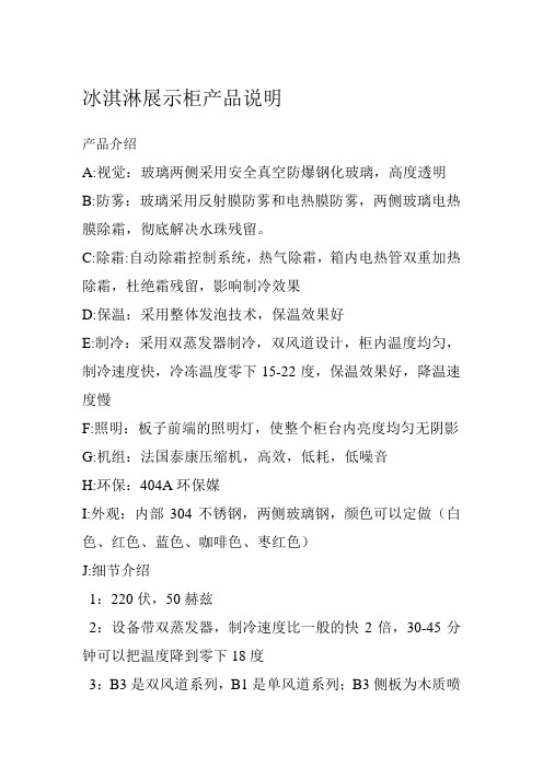
冰淇淋展示柜产品说明产品介绍A:视觉:玻璃两侧采用安全真空防爆钢化玻璃,高度透明B:防雾:玻璃采用反射膜防雾和电热膜防雾,两侧玻璃电热膜除霜,彻底解决水珠残留。
C:除霜:自动除霜控制系统,热气除霜,箱内电热管双重加热除霜,杜绝霜残留,影响制冷效果D:保温:采用整体发泡技术,保温效果好E:制冷:采用双蒸发器制冷,双风道设计,柜内温度均匀,制冷速度快,冷冻温度零下15-22度,保温效果好,降温速度慢F:照明:板子前端的照明灯,使整个柜台内亮度均匀无阴影G:机组:法国泰康压缩机,高效,低耗,低噪音H:环保:404A环保媒I:外观:内部304不锈钢,两侧玻璃钢,颜色可以定做(白色、红色、蓝色、咖啡色、枣红色)J:细节介绍1:220伏,50赫兹2:设备带双蒸发器,制冷速度比一般的快2倍,30-45分钟可以把温度降到零下18度3:B3是双风道系列,B1是单风道系列;B3侧板为木质喷漆,B1侧板为玻璃钢,B3压缩机为2HP,B1为1.5HP。
4:风冷,制冷速度快,内部温度均匀5:密度高,多层透明玻璃,保温,省电。
6:引进意大利技术,进口铜管,质量好,通过CE认证性能参数:产品名称:标准型冰淇淋展示柜产品类型:立式冷柜品牌:佳伯商用制冷设备尺寸:1250*1050*1320(1260W),1550*1050*1320(1360W)型号:JB-BQLG-A1温度:-18度(-18℃)压缩机:法国泰康制冷方式:风冷款式:盘装,圆桶另加600元颜色:自选适用场合:超市,电影院,冰淇淋店,奶茶店,烧烤店,自助餐店,火锅店,烤肉店,蛋糕店,咖啡馆,冷饮店,茶餐厅,甜品店,西饼屋,商场,酒吧,KTV,西餐店,料理店产品名称:豪华型冰淇淋展示柜产品类型:立式冷柜品牌:佳伯商用制冷设备尺寸:1280*1150*1400(1360W),1580*1150*1400(1460W)型号:JB-BQLG-B1温度:-20度(-20℃)压缩机:法国泰康制冷方式:风冷款式:盘装,圆桶另加600元颜色:自选适用场合:超市,电影院,冰淇淋店,奶茶店,烧烤店,自助餐店,火锅店,烤肉店,蛋糕店,咖啡馆,冷饮店,茶餐厅,甜品店,西饼屋,商场,酒吧,KTV,西餐店,料理店性能参数:产品类型:立式冷柜品牌:佳伯商用制冷设备制冷方式:风冷适用场合:超市,电影院,冰淇淋店,奶茶店,烧烤店,自助餐店,火锅店,烤肉店,蛋糕店,咖啡馆,冷饮店,茶餐厅,甜品店,西饼屋,商场,酒吧,KTV,西餐店,料理店产品名称尺寸(mm)功率(W)压缩机电压(V)温度(℃)款式颜色豪华型冰淇淋1280*1150*1400 1360W泰康220V -20℃盘装,圆桶另加咖啡色1580*1150*1400 1460W 黑色展示柜600元枣红色标准型冰淇淋展示柜1250*1050*1320 1260W泰康220V -18℃盘装,圆桶另加600元咖啡色1550*1050*1320 1360W 白色红色蓝色冰淇淋展示柜,冰淇淋展示冰柜,冰淇淋保鲜柜冰淇淋制冷设备,风冷冰淇淋柜,节能省电冰淇淋冷柜冰淇淋展示柜价格,冰淇淋展示柜,冰淇淋展示柜品牌盒装冰淇淋展示柜,桶装冰淇淋展示柜,圆桶冰淇淋柜8桶冰淇淋冷柜,10桶冰淇淋展示柜,6/8/10/12/16盘装冰淇淋冷柜标准型,豪华型,白色/红色/蓝色/咖啡色/枣红色冰淇淋冷柜冰淇淋店,冰淇淋车,硬质冰淇淋展示柜,雪糕冷冻柜硬质冰淇淋冷冻展示柜,哈根达斯冰淇淋展示柜冷饮,夏日冷饮冰淇淋冷藏柜,冰淇淋冷柜最新款,冰淇淋冷柜款式12盒冰淇淋柜冰淇淋展示柜冷冻柜硬质冰激凌冰棒雪糕柜饮品柜硬质冰淇淋展示柜商用冰激凌柜圆桶多功能展示柜雪糕展示柜新款冰激凌柜商用10格硬质冰淇淋展示柜硬冰淇淋冷冻雪糕柜展示柜商用冷藏展示柜冰激凌展示柜冰淇淋展示柜硬冰展示柜售后服务:本公司承诺保修12个月,并且售后服务无盲区,全国联保。
STONE半高冷藏陈列柜说明书
USER INSTRUCTION READ CAREFULLY AND KEEP WITH THE CASE用户手册使用前请仔细阅读本说明书并妥善保存,以备日后查阅STONE半高冷藏陈列柜Product ModelSTONEEpta(Qingdao) Retail Equipment Co., LtdNo.72, XinYe Road, Qingdao Hi-Tech Industrial Development Zone, Qingdao, P.R.C.China 266114爱普塔(青岛)商业设施有限公司青岛高新技术产业开发区新业路72号,青岛,中国,邮编:266114 INTRODUCTION -简介The present booklet has been formulated in a simple and rational way, in order for the reader to get deeply acquainted with his showcase . It must be read carefully and keep near the machine.The manufacturer assumes no responsibility for any personal injury or property damage which may be caused by non-compliance with the instructions contained in this booklet. Whoever operates the machine must have read this manual beforehand.本说明书简明扼要的对产品进行阐述,用户可以深入了解产品。
请在陈列柜使用前仔细阅读本说明书并妥善保管。
厂商对未按照本说明书的操作而引起的人身伤害或者财产损失不承担任何责任。
软边冷柜珊瑚浴池 FLEXI-GUARD说明书

NOTE: WATER FLOW DIRECTION SERVICE STOP (NOT FURNISHED)FIG. 1FIG. 3LEGENDA = 1/4" O.D. TUBE CONNECT (CHILLER WATER OUTLET)B = 3/8" O.D. TUBE CONNECT (CHILLER WATER INLET) SHUT OFF VALVE BY OTHERSC = 1-1/4" TRAP FURNISHED D = ELECTRICAL INLETERO8C ROUGH-INFIG. 5INSTALLATION INSTRUCTIONSFIG. 691551032, 33SEE FIG. 88, 111. Install mounting frame. See mounting frame instructions.2. Install remote chiller. Remove front panel of chiller. Slide chiller onto the shelf and position it to the left within the guides on the shelf.3. Attach solenoid valve assy to the underside of cross member of mounting frame. See Figure 7.4. Make water supply connections. Install a shut-off valve and union connection to building water supply (valve and union not provided). Turn on the water supply and flush the line thoroughly.5. Make connection between remote chiller and building supply line. Install the strainer on the chiller inlet tube. Install a 3/8" O.D. unplated copper water line between the valve and the cooler. Remove all burrs from the outside of the water line. Insert the 3/8" water line into the inlet side of the strainer by pushing it in until it reaches a positive stop, approximately 3/4" (19mm). See Figures 2 and 5. DO NOT SOLDER TUBES INSERTED INTO THE STRAINER AS DAMAGE TO THE O-RINGS MAY RESULT. Install the 1/4" x 1/4" union (provided) on the chiller outlet tube.6. Make connection between remote chiller and solenoid valve assy. Insert end of 1/4" O.D. poly tubing (provided) into union on chiller outlet and the other end into straight fitting on solenoid valve assy.7. Hang the upper panel on the mounting frame hanger. Align holes in the panel with holes in the mounting frame. Be sure that panel is engaged with hanger at top of frame before releasing it.8. Install fountain. Remove bottom cover plate on underside of fountain and save the screws. Mount the fountain to the upper panel and the wall frame with (4) 5/16" x 3/4" (19mm) long bolts and nuts (provided). Tighten securely.9. Connect solenoid valve assy and regulator holder in fountain by inserting 1/4" O.D. poly tubing (provided).10. Remove elbow from end of p-trap and attach it to drain tube. Re-attach elbow to p-trap and cut waste tube to required length using plumbing hardware and trap as a guide.11. Connect power cord of sensor to solenoid valve by running it through the back panel and connecting it as shown in Fig. 8. Connectors may be connected to either terminal on solenoid valve. Attach ground wire to solenoid valve bracket with green ground screw.12. Turn on water supply. Release air from tank by interrupting infrared beam; steady stream of water assures all air is removed. The sensor has a 30 second maximum ON time. It may be necessary to step away from beam a few times to allow chiller tank to refill. Check for leaks.13. These products are designed to operate on 20-105 PSI supply line pressure. If inlet pressure is above 105 PSI, a pressure regulator must beinstalled in the supply line. Any damage caused by reason of connecting these products to supply line pressures lower than 20 PSI or higher than 105 PSI is not covered by warranty.14. Make electrical connections to chiller. See chiller instructions.15. Check stream height from bubbler. Stream height is factory set at 35 PSI . If supply pressure varies greatly from this, remove item 11 (bottom cover plate) and adjust the screw on the regulator (item 7). Clockwise adjustment will raise stream height and counter-clockwise will lower stream height. For best adjustment stream height should hit basin approximately 6-1/2" (165mm) from the bubbler.16. Mount lower panel. Loosen the (2) #10-24 x 5/8" (16mm) screws at frame bottom lip. Slide upper tongue of lower panel under lower edge of already installed upper panel. Tighten previously loosened screws securely.17. Replace bottom cover plate to fountain basin using screws provided. Tighten securely.324NOTE: WHEN INSTALLING REPLACEMENT BUBBLER AND PEDESTAL, TIGHTEN ITEM 4 NUT ONLY TO HOLD PARTS SNUG IN POSITION. DO NOT OVER TIGHTEN.1FIG. 434343434 (TO BUBBLER)CHILLER INLET CHILLER OUTLET27FOR PARTS, CONTACT YOUR LOCAL DISTRIBUTOR OR CALL 1.800.834.4816ELKAY MANUFACTURING COMPANY • 2222 CAMDEN COURT • OAK BROOK, IL 60523 • 630.574.8484PART NO.ITEM NO. PARTS LIST12345678910111213141516171819202122232425262728293031323334DESCRIPTIONTROUBLE SHOOTING AND MAINTENANCEFIG. 86162513723188261728222930211920Orifice Assy Housing Assy PedestalBubbler Locknut DrainRegulator Holder RegulatorScrew - #10-24 X .50 PHTC StrainerFountain BodyBottom Cover Plate Back Panel Hex Nut Lower Panel Union-1/4 X 1/4Regulator Mounting Bracket Solenoid Mounting Bracket Sensor Support Bracket Solenoid Valve Assy 115VSolenoid Valve Assy 220/230V Power Cord 115V Sensor - ClearScrew- #8-18 X .37 HHSM Nut - Regulator Hex Nut #10-32Strain ReliefSpacer - 1/2 X .44Edge TrimScrew - 1/4-20 X .38 HHTC Elbow - 1/4 X 1/4Fitting - 1/4 NPTF X 1/4 O.D.Screw - #10-24 X .62 HHMS Screw - 5/16-18 X .75Hex Nut - 5/16-18Poly Tubing (Cut To Length)A5487456011C 55997C 75580C LK46450986C 61313C 11262754389055996C 28784C 5500066526837C 40045C 26833C 70683C 22525C 22526C 27240C 31375C 000000032731376C 31384C 3841700156082C 70016C 50203C 51409C 56280C 70256C 70817C 75507C 11100834389011157724389011157734389056092C1. Orifice Assy: Minerals deposits on orifice can cause water flow to spurt or not regulate. Mineral deposits may be removed from the orifice with a small round file not over 1/8" diameter or a small diameter wire. CAUTION: Do not file or cut orifice materials.2. Stream Regulator: If orifice is free of material deposits regulate water flow according to instructions on page3.3. Sensor Control: The sensor has a 2 second delay time. If sensor fails to operate valve mechanism or operates erratically, check the following: a) Ensure there are no obstructions within a 40 inch radius from the front of fountain.b) Check wire connections at the solenoid valve and at the sensor.CAUTION: Make sure unit is unplugged before checking any wiring. c) Ensure proper operation of solenoid valve. If there is an audible clicking sound yet no water flows, look for an obstruction in the valve itself or elsewhere in the water supply line.WARNING: Do not expose sensor to direct sunlight.4. Sensor Range Adjustment: The electronic sensor used in this fountain is factory pre-set for a "visual" range of 36 inches. If actual range varies greatly from this, or a different setting is desired, follow the range adjustment procedure below:a) Remove bottom cover of fountain.b) Remove sensor by removing washers and nuts that secure sensor on studs.c) Locate range adjustment screw between the red lenses of the sensor, then with a small tip screwdriver, rotate the range adjusting screw clockwise to increase range or counter-clockwise to decrease range. 1/4 turn of screw is equal to approximately 12 - 18 inches of range.CAUTION: Complete range of sensor (24 - 46 inches) is only one turn of the adjusting screw.d) Remount sensor on studs and replace bottom cover.241922FIG. 7REPAIR SERVICE INFORMATION TOLL FREE NUMBER 1.800.260.6640MF100 Mounting Frame。
海容展示柜说明书

海容展示柜说明书
海容展示柜主要是用于商店或超市中展示商品的设备,以下是其主要说明书:
1. 外观结构:海容展示柜外观一般采用不锈钢材质,具有光滑、美观、耐用等特点。
展示柜通常有上下两层,每层可放置不同种类的商品。
2. 制冷系统:展示柜采用压缩机循环制冷系统,它可以保持展示柜内的温度不变,避免商品变质。
同时,该制冷系统具有低噪音、高效节能等特点。
3. 温控系统:展示柜内的温度可通过温控系统进行调节,保证展示柜内的温度恒定。
同时,温控系统还有防止过温、过冷等保护功能。
4. 照明系统:展示柜内装有照明系统,可以让商品更加亮眼,吸引顾客的注意力。
5. 使用注意事项:在使用海容展示柜时,需要注意以下事项:
- 展示柜不得堵塞通风口和散热器。
- 展示柜在启动前需要进行预冷,避免温度变化过大。
- 展示柜的运行环境应该保持干燥、通风、无阳光直射及有害气体等。
海容展示柜是商店和超市中必不可少的重要设备,使用时应当严格按照说明书进行操作。
寄存柜存包柜使用操作说明书
电子式自助寄存柜系统使用说明书目录一、系统介绍..................................................错误!未定义书签。
1、基本组成...................................................错误!未定义书签。
2、适用范围...................................................错误!未定义书签。
3、开机显示...................................................错误!未定义书签。
4、技术指标...................................................错误!未定义书签。
二、存、取物品使用方法........................................错误!未定义书签。
1、存入物.....................................................错误!未定义书签。
2、取出物品....................................................错误!未定义书签。
三、日常管理...................................................错误!未定义书签。
1、管理命令组成................................................错误!未定义书签。
2、管理命令的执行..............................................错误!未定义书签。
四、参数设置..................................................错误!未定义书签。
1、修改设置密码...............................................错误!未定义书签。
智能储物柜说明书

长春工程学院慧鱼组智能储物柜设计说明书长春工程学院2011年12月1日目录一、基本信息 (1)二、创新构思及方案 (1)1、创新构思 (1)2、设计方案 (1)三、结构设计特点分析及创新设计说明 (2)1、特点分析 (2)2、创新说明 (3)四、主要功能及工作原理 (3)1、主要功能指标 (3)2、工作原理 (4)五、运动及动力分析 (4)六、市场化分析及应用前景 (5)七、实物照片及其说明 (6)一、基本信息设计题目:智能储物柜学生姓名:郑勇、艾喜平、陆旭东、田慧慧所在学院:机电工程学院二、创新构思及方案1、创新构思为了更好的利用家庭空间,特别是对高层空间的利用。
我们设计了智能储物柜,它的高度可至天花板,这样就能存储更多的物品,同时避免积灰。
另外,为了提高存取物品的效率,排除人工存取高层物品的危险性,我们设计了用机械手臂来自动存取。
考虑到物品的大小不一,对空间的需求不尽相同,我们在柜子上层设计了能够90°旋转的和自由升降的隔板,从而对储层空间进行调整,实现对不同体积物品的存放。
总的来说,我们的作品就是为了更好的利用空间,方便人们对物品的存取和管理,节约人力和时间,提高存取物品的效率。
2、设计方案多功能衣柜高度可至天花板。
柜前是能移动的手臂,位于工作台上。
通过丝杠可实现工作台左右移动及手臂上下移动。
工作台上设有齿轮,用来调节手臂的水平转动。
手臂上也装有齿条,用来实现手臂的收缩。
所有丝杠的转动由电机来带动。
柜前为操作区,有控制手臂移动的操作按钮,当要存取物品时,只需按按钮让手臂移动到指定的物品盒前,手臂靠磁力吸出盒子,然后取出里面的物品。
顶层设计有可旋转的挡板,当需要存储大的物品时,只需按动按钮,让右边挡板向下旋转90°或让左边挡板向下降,即可实现两个存储层变为一个大存储层的功能三、结构设计特点分析及创新设计说明1、特点分析本产品可有效的存放家居物品,作品结构简单,使用方便,操作灵活,环保,工作效率高,能大大减轻工作强度,提高工作的安全性。
冷藏商品展示机说明书

Installation & Operations ManualforANGLED MERCHANDISERS143538 Rev. B 07/17TABLE OF CONTENTS INTRODUCTION (3)STORE CONDITIONS (3)WARNING LABELS AND SAFETY INSTRUCTIONS (4)PRE-INSTALLATION INSTRUCTIONS (5)Inspection for Shipping Damage (5)INSTALLATION INSTRUCTIONS (5)General Instructions (5)Mechanical (5)Location (5)CABINET CLEANING PROCEDURES (6)SERVICE INSTRUCTIONS (6)Electrical (6)Lighted sign canopy installation (7)Special Service Situations (8)Operating Conditions and Pressures (8)Temperature Sensor, Defrost Heater, and Fan Motor Replacement (8)Electronic Refrigeration Control (9)Operations (9)Defrost & Manual Defrost (9)Temperature Setpoint (10)List of Parameters (10)Alarm Signals (10)Electrical Connections (10)Probe Connections (10)SENSOR PROBE TEMP. AND RESISTANCE (11)FAN OPERATION & VIBRATION, VOLTAGE CHECK (11)FINAL CHECK LIST (11)PARTS LIST (12)SALE AND DISPOSAL (12)WIRING DIAGRAM …………..………………………………….……………………….………………………..13-14INTRODUCTIONThank you for purchasing an Angled Ice Cream Merchandisers cabinet. This manual contains important instructions for installing, using, and servicing a this case. A parts list is included with this manual. Read all these documents carefully before installing or servicing your equipment.STORE CONDITIONSThe merchandsiers are designed to operate in the controlled environment of an air-conditioned store. The store temperature should be at or below 75°F and a relative humidity of 55% or less. At higher temperature or humidity conditions, the performance of these cases may be affected and the capacity diminished.Cabinet should not be positioned where it is directly exposed to rays of sun or near a direct source of radiant heat. This will adversely affect the case and will result in poor performance.NOTICERead this manual before installing your cabinet. Keep the manual and refer to it before doing any service on the equipment. Failure to do so could result in personal injury or damage to the cabinet.DANGERImproper or faulty hook-up of electrical components on the refrigeration units can result in severe injury or death.All electrical wiring hook-ups must be done in accordance with all applicable local, regional or national standards.NOTICEInstallation and service of the refrigeration and electrical components of the cabinet must be performed by a refrigeration mechanic and/or a licensed electrician.The portions of this manual covering refrigeration and electrical components contain technical instructions intended only for persons qualified to perform refrigeration and electrical work.This manual cannot cover every installation, use or service situation. If you need additional information, contact the cabinet’s customer service department.WARNING LABELS AND SAFETY INSTRUCTIONSThis symbol is the safety-alert symbol. When you see this symbol on your cabinet or in this manual, be alert to the potential for personal injury or damage to your equipment.Be sure you understand all safety messages and always follow recommended precautions and safe operating practices.NOTICE TO EMPLOYERSYou must make sure that everyone who installs, uses or services your cabinet is thoroughly familiar with all safety information and procedures.Important safety information is presented in this section and throughout the manual. The following signal words are used in the warnings and safety messages:DANGER: Severe injury or death will occur if you ignore the message.WARNING: Severe injury or death can occur if you ignore the message.CAUTION: Minor injury or damage to your cabinet can occur if you ignore the message.NOTICE: This is important installation, operation or service information. If you ignore the message, you may damage your cabinet.The warning and safety labels shown throughout this manual are placed on your cabinet at the factory. Follow all warning label instructions. If any warning or safety labels become lost or damaged, call our customer service department for replacements.PRE-INSTALLATION INSTRUCTIONSINSPECTION FOR SHIPPING DAMAGEYou are responsible for filing all freight claims with the delivering truck line. Inspect all cartons and crates for damage as soon as they arrive. If damage is noted to shipping crates or cartons or if a shortage is found, note this on the bill of lading (all copies) prior to signing.If damage is discovered when the cabinet is uncrated, immediately call the delivering truck line and follow up the call with a written report indicating concealed damage to your shipment. Ask for an immediate inspection of your concealed damage item. Crating material must be retained to show the inspector from the truck line.INSTALLATION INSTRUCTIONSGENERAL INSTRUCTIONS1. Be sure the equipment is properly installed by competent service people.2. Keep the equipment clean and sanitary so it will meet your local sanitation codes. Clean the cabinet with a mild detergent and water, then rinse.3. Rotate your stock so that older stock does not accumulate. This is especially important for icecream. A "First-In, First-Out" rotation practice will keep the products in good salable condition.4. Do not place product in the case when it is soft or partially thawed. Also, product should not be put in the case for at least 6 hours after it is started.5. Stock cases as quickly as possible, exposing only small quantities to store temperatures for short periods of time.6. When replacing light bars, be sure that the electrical power to the lighting circuit is turned off.MECHANICALRemove front grille and check refrigeration lines to see that they are free (not touching each other or compressor). Spin condenser fan blade to see that it is free.LOCATIONRemove cabinet from crate base and slide into location. Cabinet must be level from side to side and front to back for correct draining of coil pan and for self-closing doors to operate correctly.To comply with Sanitation requirements the cabinet must be sealed to the floor with a N.S.F. listed silicone sealant, mounted on casters, or with 6” minimum legs. 0” air space is required for the front and each side. The top and back of the cabinet must be left open for compliance.Remove shipping supports from bottom edge and top edge of doors.CABINET CLEANING PROCEDURESWARNING!To avoid electrical shock, disconnect main power supplies to the cabinetbefore beginning this procedure. May have more than one disconnect switch.The exterior of the cabinet should simply be wiped clean with a Warm damp cloth daily. This will be sufficient to keep the merchandiser looking its finest. Do not use a brush, scouring pad, or any abrasive material on the painted surfaces!To clean the interior of the cabinet, the condensing unit and power to the cabinet lights should be shut off. Disconnect all power before cleaning! All product in the cabinet should be removed and stored in an appropriate facility. All shelving, trays, Pans, etc. should be removed and cleaned separately.The interior (as well as the exterior) of the cabinet may be cleaned with a germicidal detergent at the manufacturer’s recommended concentration. Do not use any ammonia-based products as this may damage components in the cabinet. Again, do not use a brush, scouring pad, or any abrasive material on the painted surfaces. Use a soft brush or cleaner pad for built-up dirt, stains, or spills. Care should be taken not to unnecessarily soak fan motors, electrical connections, controls, or any wire raceway. Wipe all surfaces with a damp cloth. A sanitizer should then be thoroughly sprayed onto the surfaces and again wiped with a damp cloth.Remove only the necessary mechanical parts to access the condenser coil and compressor housing. Care should again be taken not to unnessarily soak fan motors, electrical connections, time clock, or any wire raceway. Check the condenser coil to insure that it is not clogged with dirt, dust, or lint. A dirty or clogged condenser coil will result indiminished performance of the cabinet. Use compressed air to blow the dirt through the condenser coil. Do not let dust or dirt accumulate on the fan blades. If dust or dirt is noticeable, simply wipe the fan blades with a damp cloth as with other surfaces. After cleaning, replace any equipment that was previously removed and start the condensing unit and return power to the lights and fans.CLEANING: As a regular maintenance routine, the condenser coil should be cleaned approx every 6 to 12 months, depending on store conditions.Keep the equipment clean and sanitary so it will meet your local sanitation codes. Wipe up all spills, clean with water and a mild detergent, then rinse with clean water. Wipe the exterior and gasket area as needed.SERVICE INSTRUCTIONSELECTRICALWARNINGBefore servicing any electrical component in the cabinet make sure all power to case is off and always use a qualified technician.It is recommended that a separate circuit be run for each cabinet to prevent another appliance blowing the fuse orHAC&R circuit breaker, causing loss of product. This circuit should be sized according to the amp rating on the cabinet data label.WARNING Before making any change, the technician should disconnect power to the cabinetFor models with LED lamp(s) without ballast only!The light fixture is designed and only suitable for specified self-ballasted LED only. In nocircumstance, should any florescent tube light be used in this fixture.•These lamp should be installed by licensed electricians per local code.•These lamps are to be used in indoor dry and damp location only.•Not suitable for wet locations•Risk of fire or electric shock•These product is intended to be used with only the specific LED lamp. It is dangerous to use any other lamp which is not specified here.LIGHTED SIGN IN CANOPY INSTALLATION1. Disconnect the power to the cabinet2. Slide the finger below the canopy lens as shown and push the lens up till it disengages from the lip ofthe canopy.3. Then slide down to take it out for service4. While installing the lens please follow the instruction as shown in the pictures.5. Make sure the top of the lens is securely positioned in the slot between the top retainer and top deck.6. Once it is in between the top slot, push the lens up to make sure it is securely placed in the groovecreated by the hem structure of the lip of the the front deck canopy area.SPECIAL SERVICE SITUATION:A. There are rare occasions when the refrigerant charge must be evacuated from a cabinet in order to performservice work. In those situation, it is recommended that a refrigerant reclaimer be used according to the EPA guidelines to eliminate the possibility of refrigerant being released to the atmosphere.B. If moisture or liquid is observed around or under this cabinet, an immediate investigation should be made byqualified personnel to determine the source of the moisture or liquid. The investigation should determine if the cabinet is malfunctioning or if there is a simple housekeeping problem. Moisture or liquid around or under a cabinet is a potential slip/fall hazard for persons walking by or working in the general area of the cabinet. Any cabinet malfunction or housekeeping problem that creates a slip/fall hazard around or under a cabinet should be corrected immediately.OPERATING CONDITIONS AND PRESSURESWith room ambient temperature of +80 F and cold cabinet (unit cycling on control):Suction Pressure 2 to 10 psigHead Pressure 240 to 260 psigTEMPERATURE SENSOR, DEFROST HEATER, AND FAN MOTOR REPLACEMENTTo change a temperature sensor (cabinet zone sensor or defrost termination sensor), simply disconnect the sensor wires from the controller and replace the new sensor in the original position. Use plastic tie to tighten the zone sensor. Insert the sensor for defrost termination firmly into the evaporator coil, in between the fins. Make sure the sensor wires do not touch or are not close to any heater rods.To change defrost heater – remove screws from drain pan and pull down – remove screws from coil mounting straps – spring straps open – remove heater shield – pull heater out of slots in coil fins.To change fan motor – disconnect fan motor leads – remove screws from fan guards and motor mounts.ELECTRONIC REFRIGERATION CONTROLCompressor When power is first turned on the controller will go through the start-up. After the start-up delay the compressor comes on. The LED indicator stays on while compressor relay is energized. Display will show actual box temperature. Picture above is the display layout. The compressor will be cycled off when the actual box temperature reaches its set point. The COMP indicator will be off..Fan The fans will run in FTC mode except when a defrost is initiated, or when the evaporator temp is above the 30o F. When in defrost mode the fan is off until the end of the defrost and the 2 minute drip time has passed. There is 2 minutes delay after a defrost before the fan comes on. If the Evaporator temperature is 35o F or below the controller will override the fan delay. FAN LED indicator is on while FAN relay is energized.Defrost The control uses time defrost with 2 defrost per day. Two defrost per day means it will occur every 12 hours. The defrost scheme can be re-set the for special applications. During defrost, the display will show dEF. The control begins timing the defrost when power is turned on.MANUAL DEFROSTDefrosting my also be induced manually by keeping the defrost button pushed for 3 seconds. Once defrost has started, the defrost will go through a defrost and drip time pull down cycle.HOW TO CHANGE THE SETPOINTHOW TO CHANGE a parameter valueLIST OF PARAMETERSHere is a list of the parameters the value of which can be changed in the programming mode, as well as their ranges.Display Symbol ParameterRange SettingSP Temperature Set Point SPL…SPH -10°FHYS Temperature Differential 1 to 255°F 10°SPL Minimum Temperature limit setpoint -50…SPH -15°FSPH Maximum Temperature limit setpoint SPH…120° 30°FAHA High Temperature alarm -50…120° 30°FALA Low Temperature Alarm 50…120° -40°FATD Temperature Alarm Delay 0…120min 30minDFR Number of Defrost Cycle per 24hr 0…24 2/dayDLI Defrost Termination Temperature -50…120° 55°FDTO Maximum Defrost Duration 1…120min 30minCONTROLLER ELECTRICAL CONNECTIONThe controller is provided with screw terminal block to connect cables with a cross section up to 2,5 mm2. Before connecting cables make sure the power supply complies with the control’s requirements. Separate the probe cables from the power supply cables, from the outputs and the power connections. Do not exceed the maximum current allowed on each relay, in case of heavier loads use a suitable external relay or contactor’s.PROBE CONNECTIONSThe probes shall be mounted with the bulb upwards to prevent damages due to casual liquid infiltration. It is recommended to place the thermostat probe away from air streams to correctly measure the average room temperature. Place the defrost termination probe among the evaporator fins in the coldest place, where most ice is formed, far from heaters or from the warmest place during defrost, to prevent premature defrost termination.SENSOR PROBE TEMPERATURE AND RESISTANCE NTC10K Temperature - ResistanceTemp (ºC) Temp(ºF) R-low (Kohm)R-center(Kohm) R-high (Kohm)-30 -22 109.522 113.347 117.294-25 -13 84.823 87.559 90.374-20 -4 66.270 68.237 70.255-15 5 52.229 53.650 55.104-10 14 41.477 42.506 43.557-5 23 33.147 33.892 34.6510 32 26.678 27.219 27.7675 41 21.630 22.021 22.41710 50 17.643 17.926 18.21015 59 14.472 14.674 14.87720 68 11.938 12.081 12.224FAN OPERATION AND VIBRATION; VOLTAGE CHECKCheck the operation of the fan blade and also check for vibration noises due to refrigerant lines rattling against one another. While the cabinet is in operation, check the voltage draw and the amperage draw versus this rating on the nameplate. Voltage should be checked at the compressor terminals while the compressor is initially starting. The Angled Ice Cream Merchandisers models are designed to operate at +/- 10% of 115/60/1. This means at time of start-up, the voltage should be between 103 volts and 126.5 volts at the compressor.FINAL CHECK LISTA. Check operating pressures.B. Check electrical requirements of unit to supply voltage.C. Set temperature control for desired temperature range.D. Check system for proper defrost settings and operation.E. Check condensing unit for vibrating or rubbing tubing. Dampen and clamp as required.PART LISTThe table below gives part numbers. Use this chart when ordering replacement parts for your cabinets. Always Advise Cabinet Serial Number When Ordering Parts.SALE AND DISPOSALOWNER RESPONSIBILITYIf you sell or give away your cabinet you must make sure that all safety labels and the Installation - Service Manual are included with it. If you need replacement labels or manuals, the cabinet manufacturer will provide them for free.The customer service department should be contacted at the time of sale or disposal of your cabinet so records may be kept of its new location.。
- 1、下载文档前请自行甄别文档内容的完整性,平台不提供额外的编辑、内容补充、找答案等附加服务。
- 2、"仅部分预览"的文档,不可在线预览部分如存在完整性等问题,可反馈申请退款(可完整预览的文档不适用该条件!)。
- 3、如文档侵犯您的权益,请联系客服反馈,我们会尽快为您处理(人工客服工作时间:9:00-18:30)。
海容sd-151d-g展示柜说明书
冷藏展示柜怎么调温度:
根据具体情况调温。
1、正常天气,春秋季,可将温度档设置为2-4档,这样箱内温度为6-7度,满足日常所需。
2、炎热天气,环境温度高,可将温度档设置为1-2档,室内温度在0度以下,可更好的保鲜食品。
3、寒冷冬季,环境温度在10-16度时,可调至5档,环境温度低于10度,可调至6-7档,箱内温度可冷藏即可。
商家在设计冷柜时,将箱内温度控制在0度到10度左右,人们可根据具体需求设置,一般控制器分为5个档,不同档温度不同,数穿会越大,箱内温度越低。
春秋可将箱温调到3档,夏天可将温度调至1-2更加省电节能。
冷藏展示柜使用要注意什么:
1、热食物要冷却后再放入冷藏柜内,因为易让食物外冷内热,从而变质,达不到保鲜的作用。
而且冷藏柜内不可存放过多的食物,太满太紧不利于空气对流,还会增加机组的负担,从而缩短使用寿命。
2、食物生熟分开放,不能混放于冰柜内,并且按所需时间合理摆放。
而且不能将食物放在蒸发器上,要放在容器内,避免在蒸发器上结冰,难以取出。
3、鲜鱼、鲜肉等食品要用塑料袋封装,再放入冷冻室。
蔬菜、水果也要将外面的水分擦干才能放入,温度最好在0度以上贮藏为宜。
4、冷藏展示柜顶上是一层很薄的钢板,不可放置过重的东西,否则会影响冷藏柜的使用,还会影响使用寿命。