海容展示柜说明书
XSD-701-52干燥柜产品说明说明书

XSD-701-52 Dry CabinetOutstanding performanceThe XSD series has an outstandingperformance for drying moisture sensitivecomponents and pcb’s.The dynamic drying unit of the 5000 seriesreaches very reliable low humidity values of≤0,5% RH and automatically regenerates ifnecessary.As a result of an insulated double metalsandwich construction a precise temperatureof 60°C can be reached with a very low powerconsumption.A radial fan and heater supports the dryingprocess and realizes an equable temperatureand moisture level in the cabinet. Therelevant process data is obtained by use of anaccurate Rotronic sensor.User friendly handlingESD featuresInsulation Data loggingOnline read outInterior lightingDoor & humidity alarm buzzerLeveling outLockable doors Sliding shelvesU 5000 series drying unitRotronic sensor Power supplyFeaturesDisplay with easy menu structureNorm (IEC 61340-5-1)ESD stainless steel body (<103 Ohm/sq).Conductive glazing (in- and outside 103 Ohm/sq). 60 mm sandwich construction with PolyuretheneIntegrated data logger over Sensor with standard 2000 measuring points (optional software is required).RS 232 interface for data (optional software is required). Low power consumption LED lightingLonger dooropenings are detected, high RH levels are detectedAdjustable legsEvery door can be locked seperately with a key.In height adjustable sliding shelves (5 pcs)≤ 0.5% RH, made in GermanyPrecision sensor, accuracy +/- 0,8 % RH, +/- 0,3°CPower cord 5 meter with IEC plugBenefits Drying time (see reference table)Recovery time after door opening Temperature stabilityTemperature settingEnergy saving consumptionNetworkIPCEuropean QualityMaintenanceFast drying time, Level 3 component, <1,4 mm = 18 hours (60°C / 1% RH) < 6 minutesThe same temperature level throughout the drying cabinet as a result of the use of a radial fan in combination with ventilation and heating canal in an insulated sandwich con-struction. Accuracy +/- 2°C Heating up to 60°CAs a result of a Dynamic dry unit, sandwich construction with insolating Polyurethene. OptionalAccording to IPC-Jstd 033C Made in GermanyEasy to service, low maintenanceTechnical Data CabinetExternal dimensions: (W x H x D) 700 x 1930/2110 x 808 mmInternal dimensions: (W x H x D) 544 x 1504 x 600 mmWeight: 142 kgWeight on shelf: 50 kgShelves (WxD): 5 pcs, 535 x 550 mm.Volume: 490 LElectric supply: 230 VAC (120 VAC optional)Power consumption: 450 W/h (60° C)Protection class: class 1, hard groundedHumidity level cabinet: ≤ 0,5 % RH can be reached with drying unit U 5002 Sensor accuracy: +/- 0,8 % RH, +/- 0,3°CTemperature accuracy: 60° C, +/- 2° CTechnical Data 52 DisplaySettings:Language MenuNominal Value HumidityNominal Value Humidity AlarmDelay Humidity Alarm (in combination with heater)Nominal Value Temperature (in combination with heater)Temperature Alarm (in combination with heater)Delay Temperature AlarmDoors AlarmInterlockingManual RegenerationDisplay:Supply voltage (supplied by drying unit) 24 VAC/DCInput 4 function keys (tactile-touch keys)Display 61 x 33 mm, white, controllable backlight, adjustable contrastSUB-D plug ( “universal“ 9-wire standard serial cable)Power consumption at 24 VDC, 40 mATechnical Data Rotronic Sensor HC2-SBased on the Airchip 3000 Technology use the HygroClip2 probes can be used for control of temperature andhumidity.The HygroClip 2 probes can be configured with theROTRONIC HW4 software and share the followingfeatures:Measurement of relative humidity and temperature.Data recording of up to 2000 relative humidity andtemperature value pairs.Programmable automatic sensor test with fail safemode and sensor drift compensation. Technical Data dry-unit U 5000 seriesDehumidifying performance: 120 g/h max.Minimal humidity 0,2% RHDehumidifying Temperature 10 – 60° CElectric supply: 230 VAC (120 VAC available)Dimensions (L x B x H): 487 x 487 x 150 mmWeight: 14 kgTest conditionsInstrument: Vaisala.Type of dew point sensor: Vaisala drycap 180MAccuracy of dew point sensor: ± 0,2° C at + 20° C (+ 68° F) Location of sensor: In the direct surrounding of cabinet sensorAmbient conditions: Humidity 50 ± 5% rH, 25° ± 2°C, Pressure 994 ± 20 hPa. Dooropenings:2 dooropenings, 15 sec. (average RH 0,70%)Performance testNumber of different types of shelves that can be mounted in cabinet:Number of shelves (47000141)56789101112 13 14 15 Distance (in mm) between shelves if equaly devided 260 210 165 165 115 115 7070707070Remaining space between top shelf and top cabinet235 190 235 40235 90430 330 235 140 40Number of drawers 1 2 3 4 5 6 7 8 9 10 11 12 13 14 15 Remaining space in mm 1366 1270 1174 1078 982 886 790 694 598 502 406 310 214 118 22XSD-701-52Dimensions mentioned in mm.Technical DrawingTechnical Drawings502553Long stripShort strip2525Drawer formationDrawer divider systemReel rack 20014005Reel rack formation, 38 reels of 8mm can be placed in 1 reel rack, totally 152 reels.Technical Drawings Different Feeder racks possibleShelves formation Honeycomb systems2 pieces of honeycomb system 1 piece of honeycomb systemSMD Reel rack with reel supports,L x W = 530 x 265 mm incl 18 reel supports;Item number 20014005Humdidity alarm signal Lamp, two-color, (orange/green or red/green), magnetically fixed, providing optical signals onoperational states and exceeded limit values. Opreates on 24 V. Item number orange/green 20016030 . Reel support,additional reel supports for 20014005:Item number 20014201Door release pedal,These foot pedals enables you to open the doors keeping your hands free, Item number 47000146 N2 auto flow system,The Auto-Flow-System is developed to use in combination with a Totech drying cabinet.The device is used for the quick removal of moisture in the cabinet after the doors hasbeen opened. The drying process is realized by using nitrogen (N²), which is add auto-matically after the doors have been closed. (by means of adjustable timer function)Item number 22613000OptionsAdditional Sliding Shelves, stainless steel sliding shelf on metal rollers, 100% extractableItem number 47000141Drawer,stainless steel drawerItem number 47000127N2 flow system,The Flow-System is developed to use in combination with a Totech dryingcabinet. The apparatus is used for adding nitrogen (N²).Item number 20010020Divider system drawer,Stainless steel devider system which enables you to create compartments with a min-imum measurement of ± 2,5 x 2,5 cm or a multiple of 2,5 cm. A standard set con-tains 5 long strips (553 mm) and 5 short strips (502 mm).Item number 47000129Cover plate for XSD shelves,prevent small items to fall throughItem number 47000132Options Additional Sliding Shelves , stainless steel sliding shelf, (without rollers)Item number 47000136Honeycomb system, Flexible stainless steel storage system for IC Tubes components & PCB’s. The width of the compartments is adjustable before installing the system in the cabinet. The number of compartments variates from 17 till 170. In total 4 systems can be Installed in a cabinet. Item number 20050100 Options HygroClip 2, Probe with maximum accuracy for all climate measurements Item number 470000027 Exchange calibrated sensor: Item number 47000040 S Feeder System, This feeder rack is suitable for Siemens S Feeder systems. Sold in combination with reel rack Item number 46204009 X Feeder System,This feeder rack is suitable for Siemens X Feeder systems. Sold in combination with reel rackItem number 46204004 Humidity calibrator Hygropalm 22, presision measuring device for calibrating sensors Set including Hygroclip sensor, case and cable: Item number 20001019 Hygropalm only: Item number 20001016version 08-06Options HW4-E software, Standard edition for use with 1 cabinet . Rotronic HW4 is a process oriented, validated software for use with the Rotronic line of digital humidity-temperature instruments. Item number 47000034 HW4-P software, Professional Edition for use with several cabinets. Rotronic HW4 is a process oriented, validated software for use with the Rotronic line of digital humidity-temperature instruments. Item number 47000031 MSL Basic software, Software solution for the monitoring of moisture sensitive components and their MSL States during storage and processing in the production. With the software the exact drying state individually for each component is monitored and displayed. Here, a complete history for each component is traceable up to the full processing. The evaluation of the drying conditions is based on the requirements of the IPC / JEDEC J-STD-033C directive. Item number 20017450 MSL software upgrade standard, Upgrade to monitor moisture sensitive components and your MSL were to an another storage facility (dry cabinet) with the standard-MSL-software . Item number 20017452 MSL advanced software, MSL upgrade offers multiple functions to the MSL standard Software. One of the possibili-ties is that it can read out multiple HC2-S sensors. To adjust storage conditions ,picking of stock, removal of used parts & more stock control. Item number 20017451Rotronic datalogger set, Including Software HW4-E-V3 and Cable AC3006 Item number 47000580Sensor accuracy: +/- 0,8 % RH, +/- 0,3°C。
软边冷柜珊瑚浴池 FLEXI-GUARD说明书

NOTE: WATER FLOW DIRECTION SERVICE STOP (NOT FURNISHED)FIG. 1FIG. 3LEGENDA = 1/4" O.D. TUBE CONNECT (CHILLER WATER OUTLET)B = 3/8" O.D. TUBE CONNECT (CHILLER WATER INLET) SHUT OFF VALVE BY OTHERSC = 1-1/4" TRAP FURNISHED D = ELECTRICAL INLETERO8C ROUGH-INFIG. 5INSTALLATION INSTRUCTIONSFIG. 691551032, 33SEE FIG. 88, 111. Install mounting frame. See mounting frame instructions.2. Install remote chiller. Remove front panel of chiller. Slide chiller onto the shelf and position it to the left within the guides on the shelf.3. Attach solenoid valve assy to the underside of cross member of mounting frame. See Figure 7.4. Make water supply connections. Install a shut-off valve and union connection to building water supply (valve and union not provided). Turn on the water supply and flush the line thoroughly.5. Make connection between remote chiller and building supply line. Install the strainer on the chiller inlet tube. Install a 3/8" O.D. unplated copper water line between the valve and the cooler. Remove all burrs from the outside of the water line. Insert the 3/8" water line into the inlet side of the strainer by pushing it in until it reaches a positive stop, approximately 3/4" (19mm). See Figures 2 and 5. DO NOT SOLDER TUBES INSERTED INTO THE STRAINER AS DAMAGE TO THE O-RINGS MAY RESULT. Install the 1/4" x 1/4" union (provided) on the chiller outlet tube.6. Make connection between remote chiller and solenoid valve assy. Insert end of 1/4" O.D. poly tubing (provided) into union on chiller outlet and the other end into straight fitting on solenoid valve assy.7. Hang the upper panel on the mounting frame hanger. Align holes in the panel with holes in the mounting frame. Be sure that panel is engaged with hanger at top of frame before releasing it.8. Install fountain. Remove bottom cover plate on underside of fountain and save the screws. Mount the fountain to the upper panel and the wall frame with (4) 5/16" x 3/4" (19mm) long bolts and nuts (provided). Tighten securely.9. Connect solenoid valve assy and regulator holder in fountain by inserting 1/4" O.D. poly tubing (provided).10. Remove elbow from end of p-trap and attach it to drain tube. Re-attach elbow to p-trap and cut waste tube to required length using plumbing hardware and trap as a guide.11. Connect power cord of sensor to solenoid valve by running it through the back panel and connecting it as shown in Fig. 8. Connectors may be connected to either terminal on solenoid valve. Attach ground wire to solenoid valve bracket with green ground screw.12. Turn on water supply. Release air from tank by interrupting infrared beam; steady stream of water assures all air is removed. The sensor has a 30 second maximum ON time. It may be necessary to step away from beam a few times to allow chiller tank to refill. Check for leaks.13. These products are designed to operate on 20-105 PSI supply line pressure. If inlet pressure is above 105 PSI, a pressure regulator must beinstalled in the supply line. Any damage caused by reason of connecting these products to supply line pressures lower than 20 PSI or higher than 105 PSI is not covered by warranty.14. Make electrical connections to chiller. See chiller instructions.15. Check stream height from bubbler. Stream height is factory set at 35 PSI . If supply pressure varies greatly from this, remove item 11 (bottom cover plate) and adjust the screw on the regulator (item 7). Clockwise adjustment will raise stream height and counter-clockwise will lower stream height. For best adjustment stream height should hit basin approximately 6-1/2" (165mm) from the bubbler.16. Mount lower panel. Loosen the (2) #10-24 x 5/8" (16mm) screws at frame bottom lip. Slide upper tongue of lower panel under lower edge of already installed upper panel. Tighten previously loosened screws securely.17. Replace bottom cover plate to fountain basin using screws provided. Tighten securely.324NOTE: WHEN INSTALLING REPLACEMENT BUBBLER AND PEDESTAL, TIGHTEN ITEM 4 NUT ONLY TO HOLD PARTS SNUG IN POSITION. DO NOT OVER TIGHTEN.1FIG. 434343434 (TO BUBBLER)CHILLER INLET CHILLER OUTLET27FOR PARTS, CONTACT YOUR LOCAL DISTRIBUTOR OR CALL 1.800.834.4816ELKAY MANUFACTURING COMPANY • 2222 CAMDEN COURT • OAK BROOK, IL 60523 • 630.574.8484PART NO.ITEM NO. PARTS LIST12345678910111213141516171819202122232425262728293031323334DESCRIPTIONTROUBLE SHOOTING AND MAINTENANCEFIG. 86162513723188261728222930211920Orifice Assy Housing Assy PedestalBubbler Locknut DrainRegulator Holder RegulatorScrew - #10-24 X .50 PHTC StrainerFountain BodyBottom Cover Plate Back Panel Hex Nut Lower Panel Union-1/4 X 1/4Regulator Mounting Bracket Solenoid Mounting Bracket Sensor Support Bracket Solenoid Valve Assy 115VSolenoid Valve Assy 220/230V Power Cord 115V Sensor - ClearScrew- #8-18 X .37 HHSM Nut - Regulator Hex Nut #10-32Strain ReliefSpacer - 1/2 X .44Edge TrimScrew - 1/4-20 X .38 HHTC Elbow - 1/4 X 1/4Fitting - 1/4 NPTF X 1/4 O.D.Screw - #10-24 X .62 HHMS Screw - 5/16-18 X .75Hex Nut - 5/16-18Poly Tubing (Cut To Length)A5487456011C 55997C 75580C LK46450986C 61313C 11262754389055996C 28784C 5500066526837C 40045C 26833C 70683C 22525C 22526C 27240C 31375C 000000032731376C 31384C 3841700156082C 70016C 50203C 51409C 56280C 70256C 70817C 75507C 11100834389011157724389011157734389056092C1. Orifice Assy: Minerals deposits on orifice can cause water flow to spurt or not regulate. Mineral deposits may be removed from the orifice with a small round file not over 1/8" diameter or a small diameter wire. CAUTION: Do not file or cut orifice materials.2. Stream Regulator: If orifice is free of material deposits regulate water flow according to instructions on page3.3. Sensor Control: The sensor has a 2 second delay time. If sensor fails to operate valve mechanism or operates erratically, check the following: a) Ensure there are no obstructions within a 40 inch radius from the front of fountain.b) Check wire connections at the solenoid valve and at the sensor.CAUTION: Make sure unit is unplugged before checking any wiring. c) Ensure proper operation of solenoid valve. If there is an audible clicking sound yet no water flows, look for an obstruction in the valve itself or elsewhere in the water supply line.WARNING: Do not expose sensor to direct sunlight.4. Sensor Range Adjustment: The electronic sensor used in this fountain is factory pre-set for a "visual" range of 36 inches. If actual range varies greatly from this, or a different setting is desired, follow the range adjustment procedure below:a) Remove bottom cover of fountain.b) Remove sensor by removing washers and nuts that secure sensor on studs.c) Locate range adjustment screw between the red lenses of the sensor, then with a small tip screwdriver, rotate the range adjusting screw clockwise to increase range or counter-clockwise to decrease range. 1/4 turn of screw is equal to approximately 12 - 18 inches of range.CAUTION: Complete range of sensor (24 - 46 inches) is only one turn of the adjusting screw.d) Remount sensor on studs and replace bottom cover.241922FIG. 7REPAIR SERVICE INFORMATION TOLL FREE NUMBER 1.800.260.6640MF100 Mounting Frame。
柜容仪使用说明书

HNGR-Ⅱ型柜容仪使用说明书江苏环能工程有限公司柜容仪使用说明书产品介绍HNGR-Ⅱ型柜容仪是用来测量干式煤气柜柜位、柜容量及活塞升降速度、气容量变化速度的仪表,兼有柜位高高限、柜位高限、柜位低限、柜位低低限、活塞升降变化速度高限报警功能,4-20mA煤气柜柜位远传输出、4-20mA活塞升降速度输出。
产品特点1.采用320×240新型点阵式大屏幕液晶显示器,能同时显示气柜容量模拟比例尺、气柜气休容量测量值和气柜活塞移动速度、气柜活塞高度、气柜容量增减速度测量值中的任意一个(这3个测量值可切换显示)。
煤气柜活塞运行速率、煤气柜煤气量变化速率7位数码显示(切换显示)。
2.设有气位高高限、气位高限、气位低限、气位低低限及气位变化速度高限屏幕显示报警功能3.设有高高限,高限和低限,低低限开关报警功能,继电器常开点输出,开关负载3A 120V AC/24VDC,最大转化电压240V AC/60VDC,开关接触电阻100mΩMax at 6VDC 1A,开关次数1000000次。
4.可以进行当前活塞高度、活塞最大运行高度(总柜高)、编码器每旋转一周活塞行程、煤气柜截横截面积、煤气柜高高限百分比、煤气柜高限百分比、煤气柜低限百分比、煤气柜低低限百分比及速率高报警值设定。
5.电源具有反向保护功能、1000V隔离,宽供电电压额定24V ,范围18—36V,电源功率小于5W。
6.4-20mA 远传输出具有宽环路电压,范围7.5-36V。
负载<500欧姆。
7.编码器信号光电隔离输入。
8.触摸屏输入,操作时只要用触笔点击屏上显示的键盘即可,十分方便、易用。
操作方法1、运行:本仪器正常情况下上电即进行正常运行.正常运行情况下显示屏如图1所示。
图1 柜容仪正常工作窗口窗口各部位作用1.气柜气体容量显示窗口,最大显示值9999999立方米。
2.气柜活塞高度,最大显示值999.99米、气柜活塞移动速度,最大显示值±999.9米、气柜容量增减速度,最大显示值99999立方米/小时,显示窗口,通过转换键对3个测量值进行转换。
海容sd-151d-g展示柜说明书

海容sd-151d-g展示柜说明书
冷藏展示柜怎么调温度:
根据具体情况调温。
1、正常天气,春秋季,可将温度档设置为2-4档,这样箱内温度为6-7度,满足日常所需。
2、炎热天气,环境温度高,可将温度档设置为1-2档,室内温度在0度以下,可更好的保鲜食品。
3、寒冷冬季,环境温度在10-16度时,可调至5档,环境温度低于10度,可调至6-7档,箱内温度可冷藏即可。
商家在设计冷柜时,将箱内温度控制在0度到10度左右,人们可根据具体需求设置,一般控制器分为5个档,不同档温度不同,数穿会越大,箱内温度越低。
春秋可将箱温调到3档,夏天可将温度调至1-2更加省电节能。
冷藏展示柜使用要注意什么:
1、热食物要冷却后再放入冷藏柜内,因为易让食物外冷内热,从而变质,达不到保鲜的作用。
而且冷藏柜内不可存放过多的食物,太满太紧不利于空气对流,还会增加机组的负担,从而缩短使用寿命。
2、食物生熟分开放,不能混放于冰柜内,并且按所需时间合理摆放。
而且不能将食物放在蒸发器上,要放在容器内,避免在蒸发器上结冰,难以取出。
3、鲜鱼、鲜肉等食品要用塑料袋封装,再放入冷冻室。
蔬菜、水果也要将外面的水分擦干才能放入,温度最好在0度以上贮藏为宜。
4、冷藏展示柜顶上是一层很薄的钢板,不可放置过重的东西,否则会影响冷藏柜的使用,还会影响使用寿命。
海尔冰柜说明书介绍,教你正确使用海尔冰柜海尔社区
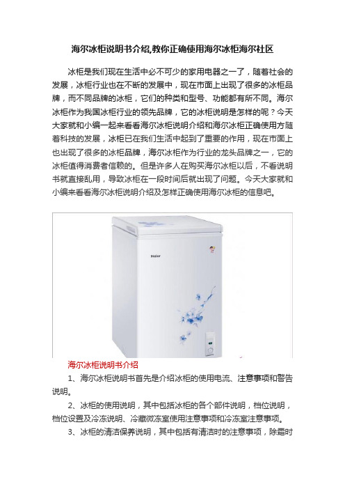
海尔冰柜说明书介绍,教你正确使用海尔冰柜海尔社区冰柜是我们现在生活中必不可少的家用电器之一了,随着社会的发展,冰柜行业也在不断的发展中,现在市面上出现了很多的冰柜品牌,而不同品牌的冰柜,它们的种类和型号、功能都有所不同。
海尔冰柜作为我国冰柜行业的领先品牌,它的冰柜说明是怎样的呢?今天大家就和小编一起来看看海尔冰柜说明介绍和海尔冰柜正确使用方随着科技的发展,冰柜已在我们生活中起到了重要的作用,现在市面上也出现了很多的冰柜品牌,海尔冰柜作为行业的龙头品牌之一,它的冰柜值得消费者信赖的。
但是许多人在购买海尔冰柜以后,不看说明书就直接乱用,导致冰柜在一段时间后就出现了问题。
今天大家就和小编来看看海尔冰柜说明介绍及怎样正确使用海尔冰柜的信息吧。
海尔冰柜说明书介绍1、海尔冰柜说明书首先是介绍冰柜的使用电流、注意事项和警告说明。
2、冰柜的使用说明,其中包括冰柜的各个部件说明,档位说明,档位设置及冷冻说明、冷藏微冻室使用注意事项和冷冻室注意事项。
3、冰柜的清洁保养说明,其中包括有清洁时的注意事项,除霜时注意事项和方法,停止使用时的注意事项。
4、冰柜常见问题介绍及解决方法,其中有噪声过大,冰柜内发出声音,冰柜不工作,门体关不严、冷气泄漏,压缩机时间保持运转,冷柜不能很好的制冷,冷柜内有异味,冷柜内结霜不均匀、结霜少是什么原因及玻璃门上出现凝露等说明。
5、介绍冰柜的规格及技术数据和注意要素。
6、冰柜的装箱单和报修政策及说明。
海尔冰柜使用方法1、检查连接线,接通冰柜的电源。
2、对冰柜进行温度设置与调节,冰柜一般都有1-7个档位,根据环境温度选择合适的档位。
3、将食物放进冰柜中(注意:首次使用前先通电,冰箱正常运转且箱内温度已经降低后再放入食物)。
4、根据食物特点分类存放,一些肉类需冷冻,新鲜蔬菜保鲜就好。
5、如长期不在家的时,需将冰柜食物取出,以免食物因停电变质产生不良气味。
海尔冰柜保养介绍冰柜要定时的清洗和保养,一般都是一个月清洗一次,以便冰柜内部有异味。
Convotherm C2020 Roll-In Rack 配件保温柜说明书
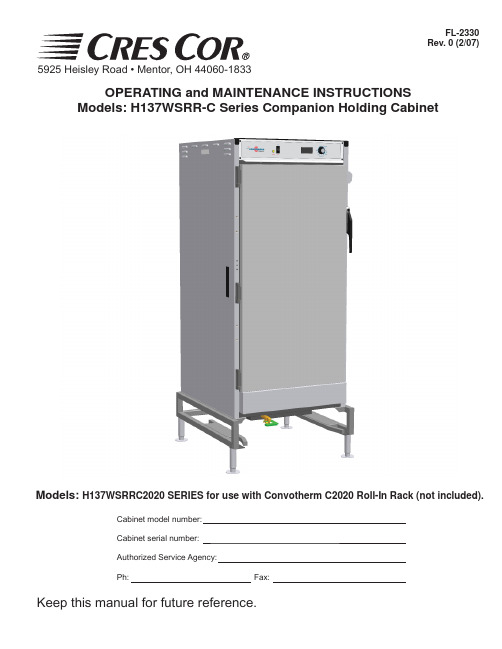
Models: H137WSRRC2020 SERIES for use with Convotherm C2020 Roll-In Rack (not included).Cabinet model number:Cabinet serial number: Authorized Service Agency:Ph:Fax:Keep this manual for future reference.OPERATING and MAINTENANCE INSTRUCTIONSModels: H137WSRR-C Series Companion Holding CabinetFL-2330Rev. 0 (2/07)5925 Heisley Road • Mentor, OH 44060-1833SUBJECT PAGEINSTALLATION INSTRUCTIONS..............................................................................................2 Illustration (Leg Adjustment), Figure 1. (2)Illustration (Drain Valve), Figure 2 (2)OPERATING INSTRUCTIONS (3)Illustration (Control Panel), Figure 3 (3)MAINTENANCE INSTRUCTIONS How to Clean the Unit...................................................................................4 Trouble Shooting Guide.................................................................................5 Replacement Parts (Cabinet)..............................................................................6 Illustration (Cabinet Parts)...................................................................................................7 Replacement Parts (Power Unit)..........................................................................................8 Wiring Diagram. (9)How to Reverse the Door Opening (10)TABLE OF CONTENTSFL-2330Rev. 0 (2/07)5925 Heisley Road • Mentor, OH 44060-1833IDENTIFYING YOUR CABINET:Look for this label on the back of your cabinet. This information is needed when calling for questions or service.OPERATING and MAINTENANCE INSTRUCTIONSModels: H137WSRR-C Series Companion Holding CabinetCompanion Holding CabinetFL-2330Rev. 0 (2/07)Page 1 of 10ELECTRICAL SPECIFICATIONS:Model No.VoltsWattsAmpsHertzPhaseNEMAHCWH2020120192016.06015-20P HCWH2020208208200010.06016-15P HCWH202024024020008.66016-15PNote: The above model numbers are basic models. They may be followed by letters: L, M, 2M, D, or ending with S.5925 Heisley Road • Mentor, OH 44060-1833HOW TO INSTALL UNIT:Remove all paper and packing material from inside of cabinet.Remove protective paper and vinyl material from outside surfaces of cabinet.Place the cabinet in a well-ventilated area.Place cabinet on level fl oor. (For cabinets with legs, adjust the legs of the cabinet to ensure proper fi t of rack into cabinet. See Fig. 1)Plug cord end into proper wall outlet.Fill water pan with 4 gallons (15 liters) of water.Make sure green drain valve is closed. See Figure 2.1.2.3.4.5.6.7. Push POWER switch to “ON.” Yellow POWER LIGHT will come on.8. Push the “SET” button on the TEMPERATURE CONTROL. The TEMPERATURE DISPLAY will show “SP1” (set point 1).9. Press “SET” again and the current set point temperature will be displayed.10. Press the ADJUST buttons to adjust to 200°F(93°C).11. Run the unit for one hour.NOTE: DO NOT PUT FOOD IN CABINET!This step is to burn off manufacturing oils and excess adhesive.Air is VERY HOT when door is opened.12. Let the cabinet cool and wipe inside clean withdetergent and hot water before fi rst use.Use of treated or soft water may be required for properoperation and to maintain warranty.OPERATING and MAINTENANCE INSTRUCTIONSModels: H137WSRR-C Series Companion Holding CabinetCompanion Holding Cabinet FL-2330Rev. 0 (2/07)Page 2 of 10Figure 1 Leg AdjustmentFigure 2 Drain Valve5925 Heisley Road • Mentor, OH 44060-1833HOW TO HOLD:No water is needed in pan.Push POWER switch to “ON.” Yellow POWER LIGHT will come on.Push the “SET” button on the TEMPERATURE CONTROL. The TEMPERATURE DISPLAY will show “SP1” (set point 1).Press “SET” again and the current set point temperature will be displayed.Press the ADJUST buttons to adjust to the desired temperature.Press “SET” to save the temperature setting.Preheat cabinet for 45 minutes.Put product into cabinet.1.2.3.4.5.6.7.8.HOLD WITH HUMIDITY:Fill water pan with HOT water.Push POWER switch to “ON.” Yellow POWER Light will come on.Push the “SET” button on the TEMPERATURE CONTROL. The TEMPERATURE DISPLAY will show “SP1” (set point 1).Press “SET” again and the current set point temperature will be displayed.Press the ADJUST buttons to adjust to the desired temperature.Press “SET” to save the temperature setting.Turn the “HUMIDITY” thermostat to No. 9.Preheat for 45 minutes.Turn “AIR” thermostat to desired temperature. (See thermostat settings below.10. Put product into cabinet1.2.3.4.5.6.7.8.9.Air is VERY HOT when door is opened.NOTES: Proper food holding temperature is 140°F/60°C or higher.SOME TYPICAL THERMOSTAT SETTINGS:Thermostat Setting ResultThermostat Setting ResultAir Humidity Cab. Temp.Humidity Air Humidity Cab. Temp Humidity 150° F Off 150° F N/A 160°F Med 160°F 50%175°F Off 175° F N/A 160°F High 160°F 95%200°F Off 200° F N/A 170°F Low 170°F 15%170°F Med 170°F 35%100°F 3½100°F 98%170°F High 170°F 85%170°F Max 170°F 90%150°F Low 115° F 98%200°F Low 200°F 7%150°F Med 150° F 95%200°F Med 200°F 15%150°F High 150° F 95%200°F High200°F 40%160°FLow160° F30%Note: These settings are based on laboratory conditions and may differ from conditions at point of use. Experiment withthe settings to determine what is best for your application.OPERATING and MAINTENANCE INSTRUCTIONSModels: H137WSRR-C Series Companion Holding CabinetCompanion Holding CabinetFL-2330Rev. 0 (2/07)Page 3 of 10Figure 35925 Heisley Road • Mentor, OH 44060-1833MAINTENANCE: WATER PAN Drain, wipe and fi ll water pan daily. (Clear vinyl drain hose is provided.)Push hose onto drain nozzle under the base.Turn knob to open the drain.1.2.MAINTENANCE: CABINETWipe the inside of cabinet after daily use. Leave doors slightly open to fully dry interior.1.2.BEFORE cleaning the cabinet: Unplug cord from wall.Do NOT hose cabinet with water.Do NOT get water on controls.Do NOT use abrasives or harsh chemicals.Cleaning hints:Wipe up spills as soon as possible.Clean cabinet regularly to avoid heavy dirt build-up.Make a test spot with cleaner.Follow manufacturer’s directions on cleaner.Do not mix cleaners.Avoid drips and splashes 1.2.3.4.5.6.HOW TO CLEAN THE UNIT:SoilCleanerMethodCABINET Inside and Outside (Stainless Steel)ROUTINE CLEANINGSoap, Ammonia, or mild *detergent and water. 1. Sponge on with cloth.2. Rinse with water.3. Wipe dry.STUBBORN SPOTS AND STAINSMild abrasive made for stainless steel.1. Apply with damp sponge or cloth.2. Rub lightly.BURNT-ON FOODS OR GREASEChemical oven cleaner for stainless steel.Follow oven cleaner manufacturer’s directions.HARD WATER SPOTS and SCALEVinegar1. Swab or wipe with cloth.2. Rinse and dry.*Mild detergents include soaps and non-abrasive cleaners.Delime or descalewater pan parts asrequired, to prevent damaging build-up. WARRANTY COVERAGE MAY BE AFFECTEDWITHOUT PROPER CLEANING.OPERATING and MAINTENANCE INSTRUCTIONSModels: H137WSRR-C Series Companion Holding CabinetCompanion Holding Cabinet FL-2330Rev. 0 (2/07)Page 4 of 105925 Heisley Road • Mentor, OH 44060-1833TROUBLE-SHOOTING CHART:FAILUREPOSSIBLE CAUSE1. Yellow light at switch does NOT light.1a. Switch is “OFF”.1b. Cord unplugged from wall outlet.1c. Circuit breaker/fuse to wall outlet blown.2. Unit does not heat.2a. Temperature Control set too low.2b. Switch is “OFF”.3. No humidity in cabinet.3a. Humidity Thermostat set too low.3b. No water in water pan.4. Unit gets too hot or won’t shut off. 4a. Defective electrical parts. UNPLUG UNIT FROM WALL OUTLET.5. Blower does not work or makes noise.5a. Defective blower.6. GFCI device trips.6a. The insulation inside the heating elements may have absorbed some moisture. This may have occurred if the cabinet has not been used for a long period of time or during shipping and storage of the cabinet. Drain the water pan if needed. Plug the cabinet into a non-GFCI outlet and set the Temperature Control to 200° (93°C). Let the cabinet run for about 1 hour to dry out the heating elements from any moisture may have been absorbed. If the circuit breaker trips, turn off cabinet, remove cord from power source, and call the Factory Authorized Service Agent. After drying the heating elements, plug cabinet into the GFCI receptacle; the cabinet should run properly. If the GFCI trips, call the factory Authorized service agent.GFCI (ground-fault circuit interrupter): A GFCI receptacle is a device that de-energizes a circuit when it detects an unsafe fl ow of current to ground. The intention of a GFCI device is to minimize the potential for an electrical shockIf cause is none of the above, refer to our list of Authorized Service Agencies.OPERATING and MAINTENANCE INSTRUCTIONSModels: H137WSRR-C Series Companion Holding CabinetCompanion Holding CabinetFL-2330Rev. 0 (2/07)Page 5 of 105925 Heisley Road • Mentor, OH 44060-1833CABINET REPLACEMENT PARTS:ITEM DESCRIPTION120V208V240V1Heater Kit, Air, 1000 Watts each 0811-*******-074-020811-074-012High Limit 0848-0600848-0600848-0603Power Cord0810-065-100810-039-020810-039-024Heater Kit, Water, 2000 Watts 0811-*******-2710811-2715Drain Valve0898-*******-0150898-0156Thermostat Probe Kit (probe only)0848-008-3-ACK0848-008-3-ACK0848-008-3-ACK7Power Unit (See Page 8)0675-0690675-0700675-0708Door - full, solid 1221-557-K -full, w/window1221-558-K -half, solid, top LH, bottom, RH 1221-560-K -half, solid, bottom LH, top, RH 1221-559-K -half, window, top LH, bottom, RH 1221-561-K -half, window, bottom LH, top, RH1221-562-K 9Gasket Kit, Body0861-17510Gasket Kit, Door 0861-26511Hinge Kit 0519-074-K 12Latch Kit 1006-122-01-K 13Tunnel0546-14114Cover, Water Pan 0761-02015Handle, Drain Valve 0911-09516Leg, Adjustable 1206-07017Handle, Pull0911-102OPERATING and MAINTENANCE INSTRUCTIONSModels: H137WSRR-C Series Companion Holding CabinetCompanion Holding Cabinet FL-2330Rev. 0 (2/07)Page 6 of 105925 Heisley Road • Mentor, OH 44060-1833OPERATING and MAINTENANCE INSTRUCTIONSModels: H137WSRR-C Series Companion Holding CabinetCompanion Holding CabinetFL-2330Rev. 0 (2/07)Page 7 of 10CABINET REPLACEMENT PARTS:5925 Heisley Road • Mentor, OH 44060-1833REPLACEMENT PARTS:ITEM DESCRIPTION120V208V240V Power Unit0675-0690675-0700675-07018Power Light 0766-*******-0950766-09519Power Switch0808-1160808-1160808-11620Thermostats, (with probe)0848-008-ACK0848-008-ACK0848-008-ACK 21Knob0595-*******-0610595-06122Terminal Block0852-*******-0930852-09323Relay0857-*******-1020857-10224Blower Kit0769-180-01-SSK0769-182-01-SSK0769-182-01-SSK 25Vent Fan0769-*******-1740769-17426Thermometer (Analog)Thermometer (Digital)5238-030-K5238-034-K5238-030-K5238-034-K5238-030-K5238-034-K27Transformer (used with digital ther-mometer)0769-*******-1590769-159 OPERATING and MAINTENANCE INSTRUCTIONS Models: H137WSRR-C Series Companion Holding CabinetCompanionHolding CabinetFL-2330Rev. 0 (2/07)Page 8 of 10REPLACEMENT PARTS FOR THE POWER UNIT:5925 Heisley Road • Mentor, OH 44060-1833WIRING DIAGRAMOPERATING and MAINTENANCE INSTRUCTIONSModels: H137WSRR-C Series Companion Holding CabinetCompanionHolding Cabinet FL-2330Rev. 0 (2/07)Page 9 of 105925 Heisley Road • Mentor, OH 44060-1833* For 208V and 240V connect wires 13 and 15 to thermostat wire 10.NOTE:To remove power unit for thermostat, blower, or thermometer maintenance, removethe outer top 7 screws and 4 front panel screws.OPERATING and MAINTENANCE INSTRUCTIONS Models: H137WSRR-C Series Companion Holding CabinetCompanionHolding CabinetFL-2330Rev. 0 (2/07)Page 10 of 10The doors are shipped with the hinges on the right side of the cabinet as standard. The doors on the cabinet are large and may require additional help when changing the hinge direction. Allow the cabinet to cool if the cabinet has been in use.Remove handle bracket and strike plates from cabinet and set aside.Remove hinge covers and set aside.Remove hex screws from door gasket bracket assembly and door cover and set aside.Remove door(s) from cabinet, rotate door(s) 180° and install onto other side of cabinet. Fordutch doors, install the bottom door onto the top position and install the top door onto the bottomposition on the other side of the cabinet.Remove screws on bottom of (lower) door and install onto top of (upper) door.Install door gasket assembly and door cover onto bottom of (lower) door.For single door, remove latch and rotate 180° and install onto holes on upper half of door. Fordutch doors, it is not necessary to change latches.Install handle bracket and strike plates onto other side of cabinet.Adjust hinges, latch(es) and door gasket bracket assembly for proper door seal.Install hinge covers.1.2.3.4.5.6.7.8.9.10.HOW TO REVERSE THE DOOR OPENING (Left hinged door shown):5925 Heisley Road • Mentor, OH 44060-1833。
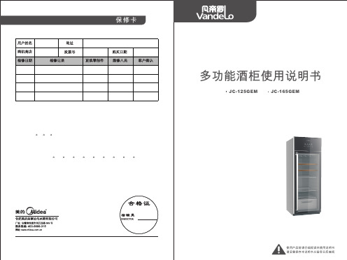
多功能酒柜使用说明书
制冰室
除了制造商推荐的方式外,不得使用机械设备或其他方式加速除霜过程。
3 12
8
功能介绍
各部分构件名称
① ② ③④ ⑤⑥ ⑦ ⑧
酒柜的正确使用
制冰盒
冷冻区 储冰盒
{
冷冻室小门
A 按键说明
B
C
D
E
F 显示屏说明
①、 ②、 ③、 ④、 ⑤、 ⑥ 、 ⑦、 ⑧、 冷冻室温度显示 除露开关显示 红酒区温度显示 照明灯开关显示 显示屏常亮显示 饮品区温度显示 触摸按键锁定显示 室内温度显示
果品盒盖板 冰 铲
产 品执行标准
GB 4706.1 GB 4706.13 GB 4343.1 GB 17625.1 GB-T23777 GB 19606
11 12
安全警告事项
本说明书包含许多重要的安全信息,请务必遵守所有的安全信息。
技术参数
安全警示符号代 表意义
该符号表示禁止的事项,其行为必须禁止。不遵守指示可能会导致产品损坏或者危及使用者 人身安全。
多功能酒柜使用说明书使用产品前请仔细阅读本使用说明书请妥善保存本说明书以备您日后查阅保修卡jc165gemjc125gem装箱单产品执行标准gb47061gb470613gb43431gb176251gbt2377713461011gb196061211技术参数1012酒柜的正确使用各部分构件名称功能介绍
请勿将包装及其它部件给儿童玩。折叠纸板和塑料薄膜可能造成窒息危险。
酒柜门无法关上
放入的食品太多 酒柜歪斜 地面是否平坦,酒柜放置是否平稳 请勿让儿童进入或攀爬酒柜,以免将小孩封入酒柜或酒柜倒下,伤及儿童。
噪声大
酒柜附件是否放在正常位置 流水声是由于制冷剂流动时产生的正常声音 环境温度和湿度较高时,玻璃门外表凝露属正常现象 玻璃门表面有凝露时,请打开除露开关 开门是否太频繁或门打开时间太长
超市立风柜、倒柜、展示柜使用规范

2020年1月19日
超市立风柜、倒柜、展示柜使用规范
19 2020年1月19日
超市立风柜、倒柜、展示柜使用规范
国产冷藏柜臂展为90cm,现我购物广场超 市使用的进口冷藏设备臂展为1.1m,风幕较 薄且风量较小,这就要求所码放的商品不能 过高。
左为放置超高的羊肉片,外观颜色已变深 (已解冻过一次)。
15
2020年1月19日
超市立风柜、倒柜、展示柜使用规范
16 2020年1月19日
超市立风柜、倒柜、展示柜使用规范
17 2020年1月19日
超市立风柜、倒柜、展示柜使用规范
奶制品专柜由于包装问题和顾客选取商品 时容易出现遗洒现象,遗洒出的液体会使柜 内产生异味、腐蚀设备,所以在出现遗洒时 要及时清理干净。其中酸奶配送的吸管和其 它用具要随时整理,如吸管掉到风口里会堵 塞风口,导致设备损坏。
28
2020年1月19日
超市立风柜、倒柜、展示柜使用规范
29 2020年1月19日
超市立风柜、倒柜、展示柜使用规范
30 2020年1月19日
超市立风柜、倒柜、展示柜使用规范
中温冷藏柜内显示温度与设备温感之间存 在温度差异,此柜上显示的为4.5 ℃,而实 际中控机房经微机处理的制冷参数已经低于 柜内显示的4.5 ℃,此原因造成主要是由于 温感差异。
33
2020年1月19日
超市立风柜、倒柜、展示柜使用规范
此次讲解中涉及的主要问题: 1、柜内商品码放过高问题。 2、柜内卫生问题。 3、为什么要定时化霜。 4、节能降耗。 5、冷冻类商品轻微融化处理技巧。
34
2020年1月19日
2020年1月19日
超市立风柜、倒柜、展示柜使用规范
- 1、下载文档前请自行甄别文档内容的完整性,平台不提供额外的编辑、内容补充、找答案等附加服务。
- 2、"仅部分预览"的文档,不可在线预览部分如存在完整性等问题,可反馈申请退款(可完整预览的文档不适用该条件!)。
- 3、如文档侵犯您的权益,请联系客服反馈,我们会尽快为您处理(人工客服工作时间:9:00-18:30)。
海容展示柜说明书
海容展示柜主要是用于商店或超市中展示商品的设备,以下是其主要说明书:
1. 外观结构:海容展示柜外观一般采用不锈钢材质,具有光滑、美观、耐用等特点。
展示柜通常有上下两层,每层可放置不同种类的商品。
2. 制冷系统:展示柜采用压缩机循环制冷系统,它可以保持展示柜内的温度不变,避免商品变质。
同时,该制冷系统具有低噪音、高效节能等特点。
3. 温控系统:展示柜内的温度可通过温控系统进行调节,保证展示柜内的温度恒定。
同时,温控系统还有防止过温、过冷等保护功能。
4. 照明系统:展示柜内装有照明系统,可以让商品更加亮眼,吸引顾客的注意力。
5. 使用注意事项:在使用海容展示柜时,需要注意以下事项:
- 展示柜不得堵塞通风口和散热器。
- 展示柜在启动前需要进行预冷,避免温度变化过大。
- 展示柜的运行环境应该保持干燥、通风、无阳光直射及有害气体等。
海容展示柜是商店和超市中必不可少的重要设备,使用时应当严格按照说明书进行操作。