某变电所毕业设计的中英文对照(中英文翻译)
供电毕设(含外文文献+中文翻译)

某钢铁企业变电所保护系统及防护系统设计1 绪论1.1 变电站继电保护的发展变电站是电力系统的重要组成部分,它直接影响整个电力系统的安全与经济运行,失恋系发电厂和用户的中间环节,起着变换和分配电能的作用,电气主接线是发电厂变电所的主要环节,电气主接线的拟定直接关系着全厂电气设备的选择、配电装置的布置、继电保护和自动装置的确定,是变电站电气部分投资大小的决定性因素。
继电保护的发展现状,电力系统的飞速发展对继电保护不断提出新的要求,电子技术、计算机技术与通信技术的飞速发展又为继电保护技术的发展不断地注入了新的活力,因此,继电保护技术得天独厚,在40余年的时间里完成了发展的4个历史阶段。
随着电力系统的高速发展和计算机技术、通信技术的进步,继电保护技术面临着进一步发展的趋势。
国内外继电保护技术发展的趋势为:计算机化,网络化,保护、控制、测量、数据通信一体化和人工智能化。
继电保护的未来发展,继电保护技术未来趋势是向计算机化,网络化,智能化,保护、控制、测量、数据通信一体化发展。
微机保护技术的发展趋势:①高速数据处理芯片的应用②微机保护的网络化③保护、控制、测量、信号、数据通信一体化④继电保护的智能化1.2本文的主要工作在本次毕业设计中,我主要做了关于某钢铁企业变电所保护系统及防护系统设计,充分利用自己所学的知识,严格按照任务书的要求,围绕所要设计的主接线图的可靠性,灵活性进行研究,包括:负荷计算、主接线的选择、短路电流计算,主变压器继电保护的配置以及线路继电保护的计算与校验的研究等等。
1.3 设计概述1.3.1 设计依据1)继电保护设计任务书。
2)国标GB50062-92《电力装置的继电保护和自动装置设计规范》3)《工业企业供电》1.3.2 设计原始资料本企业共有12个车间,承担各附属厂的设备、变压器修理和制造任务。
1、各车间用电设备情况用电设备明细见表1.1所示。
表1.1 用电设备明细表2、负荷性质本厂大部分车间为一班制,少数车间为两班或者三班制,年最大有功负荷利用小时数为h2300。
毕业设计外文原文+翻译(电力系统)
河南理工大学HENAN POLYTECHNIC UNIVERSITY英文文献翻译En glish literature tran slati on学院:电气工程与自动化学院专业班级:___________ 电气11-4班_______ 姓名: __________________ 宋家鹏_______ 学号:311008001120 __________ 扌旨导老师:____________ 汪旭东_______2014年6月5日河南理工大学HENAN POLYTECHNIC UNIVERSITY2.5 对称三相电路在这一部分,我们介绍三相对称电路的一下几个话题:丫连接,相电压,线电压,线电流,△形连接负荷,△ - Y变换,以及等效的相图。
c Ca Ab B图2-10三相Y连接电源带Y连接对称负荷电路图对称Y连接图2-10显示的是一个三相Y连接电源带Y连接对称负荷电路图。
对于Y连接电路,每个相的中性点是连接起来的。
在图2-10中电源中性点标记的是n,而负载中性点标记的是N。
把三相电源假设为理想电源,即阻抗忽略不计。
同时,电源和负载之间线路阻抗,中性点n与N之间的线路阻抗也可忽略不计。
三相负荷是对称的,意味着三相之中任意两相间的阻抗是相同的。
对称相电压在图2-10中,三相电源的终端呗标记为a、b、c,电源相电压标记为E an ,E bn,E cn,当电源的三相电压有相同的幅度,任意两相之间互差120度角时,电源是对称的。
当以E an 作为参考相量时,相电压的幅值是10V,对称三相相电压如下所示:E an=10 0E bn10 120 10 240 (2.5.1 )E cn10 120 10 240河南理工大学HENAN POLYTECHNIC UNIVERSITY图2-11以E an 作为参考的对称正序相电压向量图当E an 超前E bn 120度,E bn 超前E cn 以120度角时,此时的相序称为正相序或 者abc 相序。
供电毕设(含外文文献+中文翻译)

供电毕设(含外文文献+中文翻译)某钢铁企业变电所保护系统及防护系统设计1 绪论1.1 变电站继电保护的发展变电站是电力系统的重要组成部分,它直接影响整个电力系统的安全与经济运行,失恋系发电厂和用户的中间环节,起着变换和分配电能的作用,电气主接线是发电厂变电所的主要环节,电气主接线的拟定直接关系着全厂电气设备的选择、配电装置的布置、继电保护和自动装置的确定,是变电站电气部分投资大小的决定性因素。
继电保护的发展现状,电力系统的飞速发展对继电保护不断提出新的要求,电子技术、计算机技术与通信技术的飞速发展又为继电保护技术的发展不断地注入了新的活力,因此,继电保护技术得天独厚,在40余年的时间里完成了发展的4个历史阶段。
随着电力系统的高速发展和计算机技术、通信技术的进步,继电保护技术面临着进一步发展的趋势。
国内外继电保护技术发展的趋势为:计算机化,网络化,保护、控制、测量、数据通信一体化和人工智能化。
继电保护的未来发展,继电保护技术未来趋势是向计算机化,网络化,智能化,保护、控制、测量、数据通信一体化发展。
微机保护技术的发展趋势:①高速数据处理芯片的应用②微机保护的网络化③保护、控制、测量、信号、数据通信一体化④继电保护的智能化1.2本文的主要工作在本次毕业设计中,我主要做了关于某钢铁企业变电所保护系统及防护系统设计,充分利用自己所学的知识,严格按照任务书的要求,围绕所要设计的主接线图的可靠性,灵活性进行研究,包括:负荷计算、主接线的选择、短路电流计算,主变压器继电保护的配置以及线路继电保护的计算与校验的研究等等。
1.3 设计概述1.3.1 设计依据1)继电保护设计任务书。
2)国标GB50062-92《电力装置的继电保护和自动装置设计规范》3)《工业企业供电》1.3.2 设计原始资料本企业共有12个车间,承担各附属厂的设备、变压器修理和制造任务。
1、各车间用电设备情况用电设备明细见表1.1所示。
表1.1 用电设备明细表2、负荷性质本厂大部分车间为一班制,少数车间为两班或者三班制,年最大有功负荷利用小时数为h2300。
外文翻译-建筑电气专业毕业设计英文翻译-变压器外文文献翻译-中英文对照翻译

中文2795字第一部位译文部分变压器摘要:变压器是变电所的主要设备,功能是实现电网电压的等级变换,基本工作原理是电磁感应。
变配电所是实现电压等级变换和电能分配的场所。
对供电电源进行电压等级变换,应对电能进行重新分配的场所称为变电所。
建筑变电所是供配电系统的枢纽,供电电源由电网引到变电所,在变电所完成降压,电能分配等功能。
关键词:变电所;变压器;继电保护;1. 介绍要从远端发电厂送出电能,必须应用高压输电。
因为最终的负荷,在一些点高电压必须降低。
变压器能使电力系统各个部分运行在电压不同的等级。
本文我们讨论的原则和电力变压器的应用。
2. 双绕组变压器变压器的最简单形式包括两个磁通相互耦合的固定线圈。
两个线圈之所以相互耦合,是因为它们连接着共同的磁通。
在电力应用中,使用层式铁芯变压器(本文中提到的)。
变压器是高效率的,因为它没有旋转损失,因此在电压等级转换的过程中,能量损失比较少。
典型的效率范围在92到99%,上限值适用于大功率变压器。
从交流电源流入电流的一侧被称为变压器的一次侧绕组或者是原边。
它在铁圈中建立了磁通φ,它的幅值和方向都会发生周期性的变化。
磁通连接的第二个绕组被称为变压器的二次侧绕组或者是副边。
磁通是变化的;因此依据楞次定律,电磁感应在二次侧产生了电压。
变压器在原边接收电能的同时也在向副边所带的负荷输送电能。
这就是变压器的作用。
3. 变压器的工作原理当二次侧电路开路是,即使原边被施以正弦电压Vp ,也是没有能量转移的。
外加电压在一次侧绕组中产生一个小电流Iθ。
这个空载电流有两项功能:(1)在铁芯中产生电磁通,该磁通在零和±φm 之间做正弦变化,φm 是铁芯磁通的最大值;(2)它的一个分量说明了铁芯中的涡流和磁滞损耗。
这两种相关的损耗被称为铁芯损耗。
变压器空载电流Iθ一般大约只有满载电流的2%—5%。
因为在空载时,原边绕组中的铁芯相当于一个很大的电抗,空载电流的相位大约将滞后于原边电压相位90º。
变频电机设计及调速系统研究-外文文献及翻译
本科生毕业设计(论文)外文翻译毕业设计(论文)题目:变频电机设计及调速系统研究外文题目:Performance Analysis of Z-source Inverter Fed Induction Motor Drive 译文题目:Z源逆变器的驱动性能分析学生姓名:专业:电气工程及其自动化指导教师姓名:评阅日期:Z源逆变器的驱动性能分析摘要:本篇论文提出了三次谐波输入逆变器时最大恒定升压控制的仿真及其性能分析,该方法可在固定的调制指数下获得最大的电压升压。
Z源逆变器是一种全新的电力转换概念,其主要应用于燃料电池汽车。
相比较于传统的逆变器,Z源逆变器有着明显的优势,它可以应用于所有的交/直流转换。
并且所有传统PWM 调制法都可以应用于Z源逆变器的控制。
最大升压控制法通过保持固定的直通占空比消除了电感电流和电容电压的低频脉动,同时减少了开关器件的电磁应力。
最大升压法仅适用于相对较高的输出频率,然而最大恒定升压控制法中的Z 源网络的设计仅取决于开关频率,而与输出频率无关。
在本文中Z源逆变器的升压系数、输出直流线电压、电容电压、输出交流电压、电压增益等参数由调制指数固定的最大升压控制法所确定,并由仿真和实验验证。
关键词传统逆变器,Z源逆变器,升压系数,PWM,三次谐波,电压增益。
1.引言逆变器是直流/交流的转换设备。
以直流形式输入的电压或电流被转换为交流电压输出。
改变直流输入或改变逆变器增益都可以对输出电压进行控制。
传统逆变器广泛应用于工业中的变速驱动及其他场合,根据其输入的不同可分为两种:a电压源逆变器。
b电流源逆变器。
脉冲宽度调制可以控制逆变器的增益,不同的PWM技术就是用来控制此类逆变器。
PWM控制技术还降低了输出信号的谐波失真并且提高了逆变器的性能。
三次谐波输入PWM的方法消除了输出波形中的三次谐波分量,而且提供了比常规PWM技术更大范围的调制指数。
这些PWM 波形可以通过使用带无源和有源元件的模拟电路产生,也可以由微处理器和微控制器产生[4]。
电气工程及其自动化本科毕业设计(论文)中英文对照翻译-电力系统

本科毕业设计(论文)中英文对照翻译院(系部)电气工程与自动化学院专业名称电气工程及其自动化年级班级03级2班学生姓名指导老师电力系统1 电力的技术特点电力具有独特的技术特点,这使得电力工业具有独特的行业特点。
1.无形性。
用户不能用人体感官直接察觉千瓦时的用电量。
2.质量。
供电质量可由供电连续性或供电可靠性、在标准电压等级下的电压均等性、交流电压频率的正确不变性来度量。
3.电力的贮存。
与大多数行业不同,电力部门必须随时根据用电的需求生产出电力来,因为电能无法贮存。
4.对供电负责。
电由电力部门输送到用户,因此必须对安全、可靠供电负责。
5.对公众的安全。
电力部门须对公众及其技术人员提供稳妥的保护。
2 电力系统的规划预期到电力部门的供电负荷将持续增长,电力系统的容量也持续增大。
远期规划主要是保证这种扩建在技术上是适宜的,在造价上是合理的,与增长模式是相符的。
远期规划者碰到的困难包括:不同地域和不同时间负荷增长的不确定性、新发明新技术发展的可能性。
优异的系统规划要努力做到全系统设计的最优化,而不能为了系统某部分造价的最小化而不顾其它部分的影响。
近年来,已经强调了规划和运行的经济性。
现在则越来越强调可靠性和环境方面的因素。
在作出规划前,须要仔细考虑许多因素:(1)设备的决策具有远期效应,这需要15—25年的预期和研究。
(2)有许多发电途径可选择:核电、基荷火电、中等规模燃气轮机发电或水电,以及大型、中型、小型电厂和各种形式的蓄能。
(3)有多种送电途径可选择,例如由交流或直流,架空线或地下电缆送电并有各种电压等级。
(4)规划决策受负荷管理技术和负荷模式的影响。
(5)有关因素存在不确定性。
如将来燃料价格货币的利率资金的来源设备的强迫停运率新技术环境的要求。
3 电力分配3.1 最初的分配系统发电厂和最后的各支路之间的分配线路叫做最初的分配系统。
在这两个电力系统之间传输有多种方法. 其中最常见的两种方法是辐射式和环绕式。
电气自动化专业毕业设计英文翻译
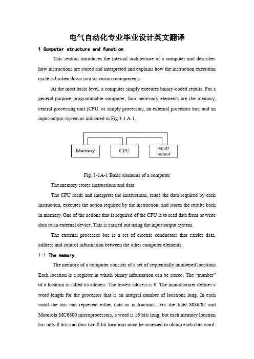
电气自动化专业毕业设计英文翻译1 Computer structure and functionThis section introduces the internal architecture of a computer and describes how instructions are stored and interpreted and explains how the instruction execution cycle is broken down into its various components.At the most basic level, a computer simply executes binary-coded results. For a general-purpose programmable computer, four necessary elements are the memory, central processing unit (CPU, or simply processor), an external processor bus, and an input/output system as indicated in Fig.3-1 A-1.Fig. 3-1A-1 Basic elements of a computerThe memory stores instructions and data.The CPU reads and interprets the instructions, reads the data required by each instruction, executes the action required by the instruction, and stores the results back in memory. One of the actions that is required of the CPU is to read data from or write data to an external device. This is carried out using the input/output system.The external processor bus is a set of electric conductors that carries data, address and control information between the other computer elements.1-1 The memoryThe memory of a computer consists of a set of sequentially numbered locations. Each location is a register in which binary information can be stored. The “number”of a location is called its address. The lowest address is 0. The manufacturer defines a word length for the processor that is an integral number of locations long. In each word the bits can represent either data or instructions. For the Intel 8086/87 and Motorola MC6800 microprocessors, a word is 16 bits long, but each memory location has only 8 bits and thus two 8-bit locations must be accessed to obtain each data word.In order to use the contents of memory, the processor must fetch the contents of the right location. To carry out a fetch, the processor places (enables) the binary-coded address of the desired location onto the address lines of the external processor bus. The memory then allows the contents of the addressed memory location to be read by the processor. The process of fetching the contents of a memory location does not alter the contents of that location.Instructions in memory Instructions stored in memory are fetched by the CPU and unless program branches occur, they are executed in the sequence they appear in memory. An instruction written as a binary pattern is called a machine-language instruction. One way to achieve meaningful patterns is to divide up the bits into fields as indicated in Fig. 3-1A-2, with each field containing a code for a different type of information.0001 0101 1000 XXXX 0100 0001 1000 XXXX 0011 XXXX XXXX 0100 Fields Opcode Immediate code Operand data Branch addressSet ‘5’ in location 8 Subtract ‘1’ f rom location 8 If zero, bran ch to location 416-bit instruction words... ... XXXX : not u sed (or “don ’t care”)Fig. 3-1A-2 Arrangement of program and data in memoryEach instruction in our simple computer can be divided up into four fields of 4 bits each. Each instruction can contain operation code (or opcode, each instruction has a unique opcode), operand address, immediate operands, branch address.In a real instruction set there are many more instructions. There is also a much large number of memory locations in which to store instructions and data. In order to increase the number of memory locations, the address fields and hence the instructions must be longer than 16 bits if we use the same approach. There are a number of ways to increase the addressing range of the microprocessor withoutincreasing the instruction length: variable instruction field, multiword instructions, multiple addressing modes, variable instruction length. We will not discuss them in detail.Data in memory data is information that is represented in memory as a code. For efficient use of the memory space and processing time, most computers provide the capability of manipulating data of different lengths and representations in memory. The various different representations recognized by the processor are called its data types. The data types normally used are: bit, binary-coded decimal digit (4-bit nibble, BCD), byte (8 bits), word (2 bytes), double word (4 bytes).Some processors provide instructions that manipulate other data types such as single-precision floating-point data types (32bits) and double-precision floating-point data types (64 bits). There is another type of data—character data. It is also usually represented in 8 bits. Each computer terminal key and key combination (such as shift and control functions) on a standard terminal keyboard has a 7-bits code defined by the American Standard Code for Information Interchange (ASCII).Type of memory In the applications of digital control system, we also concerned with the characteristics of different memory techniques. For primary memory, we need it to be stored information temporarily and to be written and got information from successive or from widely different locations. This type memory is called random-access memory (RAM). In some case we do not want the information in memory to be lost. So we are willing to use special techniques to write into memory. If writing is accomplished only once by physically changing connections, the memory is called a read-only memory (ROM). If the interconnection pattern can be programmed to be set, the memory is called a programmable read-only memory (PROM). If rewriting can be accomplished when it is necessary, we have an erasable programmable read-only memory (EPROM). An electronically erasable PROM is abbreviated EEPROM.1-2 The CPUThe CPU’s job is to fetch instructions from memory and execute these instructions. The structure of the CPU is shown in Fig. 3-1A-3. It has four maincomponents: an arithmetic and logical unit (ALU), a set of registers, an internal processor bus and controller.Fig.3-1A-3 Central processing unit (CPU)These and other components of the CPU and their participation in the instruction cycle are described in the following sections.Arithmetic and Logical Unit (ALU) The ALU provides a wide arithmetic operations, including add, subtract, multiply, and divide. It can also perform Boolean logic operations such as AND, OR, and COMPLEMENT on binary data. Other operations, such as word compares, are also available. The majority of computer tasks involve the ALU, but a great amount of data movement is required in order to make use of the ALU instructions.Registers A set of registers inside the CPU in used to store information.Instruction register When an instruction is fetched, it is copied into the instruction register, where it is decoded. Decoding means that the operation code is examined and used to determine the steps of the execution sequence.Programmer’s model of the CPU The collection of registers that can be examined or modified by a programmer is called the programmer’s model of the CPU. The only registers that can be manipulated by the instruction set, or are visibly affected by hardware inputs or the results of operations upon data, are the registers represented in the model.Flag register The execution sequence is determined not only by the instruction but also by the results of the previous instructions. For example, if an addition is carried out in the ALU, data on the result of the addition (whether the result is positive, negative, or zero, for example) is stored in what is known as a flag register, status register, or condition register. If the next instruction is a conditional branch instruction, the flag word is tested in that instruction to determine if a branch if a branch is required.Program counter (instruction pointer)The address of the next instruction is located in a register called the program counter.Data registers When an instruction uses the registers to store data, the reference to the register in the instruction is called register addressing. The reasons of making use of the internal registers to store data are that they can make the instructions shorter and make execution faster.Address registers The internal registers can also be used for the storage of address of data in memory data. In such a case, the instruction word contains a register number (i.e. a register address). In the register is contained the address of memory data to be used in the instruction. This form of addressing is called register indirect addressing. The contents of the register are said to point to the data in memory.Internal Processor Bus The internal processor bus moves data between internal register. A bus is a set of closely grouped electric conductors that transfers data, address, and control information between functional blocks of the CPU. Data from a source register can be passed to a destination register when both are enabled onto (connected to) the bus.Controller The controller provides the proper sequence of control signals for each instruction in a program cycle to be fetched from memory. A total program cycle comprises many instruction cycle, each instruction cycle can be divided up into its component machine cycles and each machine cycle comprises a number of clock cycle.In order to fetch an instruction, for example illustrated in Fig.3-1A-4, the addressin the program counter is placed on the address lines of the external bus (AB) at the onset of clock cycle C1. Simultaneously, using a code on the control lines of the bus (CB), the CPU informs all devices attached to the bus that an “opcode” fetch machine cycle is being executed by the CPU. The memory allows the memory address to select the memory location containing the instruction. At C2 the controller places a “read”command onto the control bus which allows the memory data to be placed onto the data bus. The controller then gates the data into the instruction register and removes the read command from the control bus in C3. At C4, the controller removes the address from the address bus and begins to decode the operation-code portion of the instruction to see what steps are required for execution. The decoding operation may take several more clock cycle at the end of which the “opcode fetch” machine cycle.Fig. 3-1A-4 A timing diagram for "operation-code fetch "External attention requests It is often necessary to stop the normal instruction processing sequence. One type of external attention request is the reset request. In the case of an unrecoverable error, a computer system may be required to reset itself .This would have the effect of initializing all important registers in the system and starting instruction execution from a standard memory location-usually location 0.An input that is more commonly activated during the normal course of events is the interrupt request. An interrupt request signal from an external device can cause theCPU to immediately execute a service subroutine which carries out the necessary actions. After completing the service subroutine, the processor will continue the task from which it was originally interrupted.The third type of input is the bus request, or direct memory access(DMA) request. It is possible to have a terminal interface that stores up all the characters in a line of text until it receives a "carriage return." Then the interface requests the use of the system bus, at which time the complete line of data is transferred to memory as fast as possible. In this way the processor simply becomes inactive until the transfer is completed.1-3 BusesThe bus is the most important communication system in a computer system. Under control of the CPU, a data source device and a data destination device are "enabled" onto(equivalent to being connected to) the bus wires for a short transmission.External processor bus The internal processor bus described in Sec. is connected to the external processor bus by a set of bus buffers located on the microprocessor integrated circuit.System bus The microcomputer board can communicate with other boards by connecting its bus to an external system bus through a connector.1-4Computer Input and OutputA set of registers external to the CPU is associated with what is known as the input/output (I/O) system. The I/O system is connected to the external processor bus using control, address, and data buses through an I/O registers in an interface. There are basically two ways that are used to address I/O register.In the first method, called I/O-mapped input/output, the operation code itself has special I/O instructions that address a numbered register in the interface called an I/O port.The second method of addressing I/O registers gives the I/O ports addresses that lie within the memory address range of the CPU. This is called memory-mapped I/O. Of course there must not be any memory locations at the same address as I/Olocations.One of the benefits of the memory-mapped approach is that the full range of memory addressing modes is available to the addressing of I/O registers.2Fundamentals of Computer and Networks2-1 Organization of Computer SystemA computer is a fast and accurate symbol manipulating system that is organized to accept, store, and process data and produce output results under the direction of a stored program of instructions. This section explains why a computer is a system and how a computer system is organized. Key elements in a computer system include input, processing, and output devices. Let's examine each component of the system in more detail.Input Devices Computer system use many devices for input purpose. Some INPUT DEVICES allow direct human/machine communication, while some first require data to be recorded on an input medium such as a magnetizable material. Devices that read data magnetically recorded on specially coated plastic tapes or flexible or floppy plastic disks are popular. The keyboard of a workstation connected directly to (or ONLINE to) a computer is an example of a direct input device. Additional direct input devices include the mouse, input pen, touch screen, and microphone. Regardless of the type of device used, all are components for interpretation and communication between people and computer systems.Central Processing Unit The heart of any computer system is the central processing unit (CPU). There are three main sections found in the CPU of a typical personal computer system: the primary storage section, the arithmetic-logic section, and the control section. But these three sections aren't unique to personal computers. They are found in CPUs of all sizes.Output Device Like input units, output device are instruments of interpretation and communication between humans and computer system of all size. These device take output results from the CPU in machine-coded form and convert them into a form that can be used (a) by people (e.g. a printed and /or displayed report) or (b) asmachine input in another processing cycle.In personal computer systems, display screen and desktop printers are popular output devices. Larger and faster printers, many on-line workstations, and magnetic tape drives commonly found in large systems.The input/output and secondary storage units are sometimes called peripheral devices (or just peripherals). This terminology refers to the fact that although these devices are not a part of the CPU, they are often located near it. Besides, a computer system also includes buses, ROM(read only memory), RAM(random access memory), parallel port and serial port, hard disk, floppies and CD(compact disk)drive, and so on.2-2 Operating SystemOperating systems have developed over the past thirty years for two main purposes. First, they provide a convenient environment for the development and execution of programs. Second, operating systems attempt to schedule computational activities to ensure good performance of the computing system.The operating system must ensure correct operation of the computer system. To prevent user programs form interfering with the proper operation of the system, the hardware was modified to create two modes: user mode and monitor mode. Various instructions (such as I/O instructions and halt instructions) are privileged and can only be executed in monitor mode. The memory in which the monitor resides must also be protected from modification by the user. A timer prevents infinite loops. Once these changes (dual mode, privileged instructions, memory protection, timer interrupt) have been made to the basic computer architecture, it is possible to write a correct operating system.As we have stated, operating systems are normally unique to their manufacturers and the hardware in which they are run. Generally, when a new computer system is installed, operational software suitable to that hardware is purchased. Users want reliable operational software that can effectively support their processing activities.Though operational software varies between manufacturers, it has similarcharacteristics. Modern hardware, because of its sophistication, requires that operating systems meet certain specific standards. For example, considering the present state of the field, an operating system must support some form of on-line processing. Functions normally associated with operational software are:1)Job management;2)Resource management;3)Control of I/O operations4)Error recovery;5)Memory management.2-3 NetworksCommunication between distributed communities of computers is required for many reasons. At a national level, for example, computers located in different parts of the country use public communication services to exchange electronic messages (mail) and to transfer files of information from one computer to another. Similarly, at a local level within, say, a single building, distributed communities of computer-based workstations use local communication networks to access expensive shared resources—for example, printers and disks tapes and copiers, etc.—that are also managed by computers. Clearly, as the range of computer-based products and associated public and local communication networks proliferate, computer-to-computer communication will expand rapidly and ultimately dominate the field of distributed systems.Although the physical separation of the communicating computers may vary considerably from one type of application to another, or, at the heart of any computer communication network is the data communication facility which, may be a PSDN, a private LAN or perhaps a number of such networks interconnected together. However, irrespective of the type of data communication facility, an amount of hardware and software is required within each attached computer to handle the appropriate network-dependent protocols. Typically, these are concerned with the establishment of a communication channel access the network and with the control of the flow of messages across this channel. The provision of such facilities is only part of thenetwork requirements, however, since in many applications the communicating computers may be of different forms of data representation interface between user (application) programs, normally referred to as application processes or APs, and the underlying communication services may be different. For example, one computer may be a small single-user computer, while another may be a large multi-user system.3 Stepper motorStepper motor is the electric pulse signals into angular displacement or linear displacement of the open-loop stepper motor control element pieces. In the case of non-overloaded, the motor speed, stop position depends only on the pulse frequency and pulse number, regardless of load changes, when the driver receives a step pulse signal, it will drive a stepper motor to Set the direction of rotation of a fixed angle, called the "step angle", which the angle of rotation is fixed step by step operation. Number of pulses can be controlled by controlling the angular displacement, so as to achieve accurate positioning purposes; the same time by controlling the pulse frequency to control the motor rotation speed and acceleration, to achieve speed control purposes.3-1 WorkInduction motor is a stepper motor, does it work is the use of electronic circuits, the DC power supply into a time-sharing, multi-phase timing control current, this current stepper motor power supply, the stepper motor to work properly , The drive is sharing power supply for the stepper motor, the polyphase timing controller.Although the stepper motor has been widely used, but the stepper motor does not like a normal DC motor, AC motor in the conventional use. It must be double-ring pulse signal; power driver circuit composed of the control system can be used. Therefore, it is not easy with a good stepping motor, which involves mechanical, electrical, electronics and computers, and much other specialized knowledge.As the stepper motor actuators, electromechanical integration, one of the key products, widely used in a variety of automatic control systems. With the developmentof microelectronics and computer technology, increasing demand for stepper motor has applications in all areas of the national economy.3-2 CategoriesNow more commonly used include the reaction of step motor stepper motor (VR), permanent magnet stepper motor (PM), hybrid stepper motors (HB) and single-phase stepper motor.3-3 Permanent magnet stepper motorPermanent magnet stepper motor is generally two-phase, torque, and smaller, usually 7.5 degree step angle or 15 degrees;Permanent magnet stepper motor output torque, dynamic performance, but a large step angle.3-4 Reaction Stepper MotorReaction is generally three-phase stepping motor can achieve high torque output, step angle of 1.5 degrees is generally, but the noise and vibration are large. Reaction by the stepper motor rotor magnetic circuit made of soft magnetic materials, a number of the stator phase excitation winding, the use of permeability changes in torque.Step Motor simple structure, low production costs, step angle is small; but the dynamic performance is poor.3-5 Hybrid Stepping MotorHybrid Step Motor combines reactive, permanent magnet stepper motors of both, it's a small step angle, contribute a large, dynamic performance, is currently the highest performance stepper motor. It is also sometimes referred to as Permanent Magnet Induction Stepping Motor. It consists of two phases and the five-phase: the general two-phase step angle of 1.8 degrees and the general five-phase step angle 0.72 degrees. The most widely used Stepper Motor. Stepper motor drive for energy saving 3-6 Three-phase stepper motor drive special features:◆180% low torque output, low frequency characteristics of a good run◆Maximum output frequency 600Hz, high-speed motor control◆full range of detection of protection (over voltage, under voltage, overload)instantaneous power failure restart◆acceleration, deceleration, such as dynamic change in the stall protection functionto prevent◆Electrical dynamic parameters of automatic recognition function to ensurestability and accuracy of the system◆quick response and high-speed shutdown◆abundant and flexible input and output interface and control, versatility◆use of SMT production and three full-mount anti-paint treatment process, productstability and high◆full range of Siemens IGBT power devices using the latest, to ensure the qualityof high-quality3-7 Basic principlesUsually for the permanent magnet rotor motor, when current flows through the stator windings, the stator windings produce a magnetic field vector. The magnetic field will lead to a rotor angle of the magnetic field makes the direction of a rotor and the stator's magnetic field direction. When the stator magnetic field vector rotating at an angle. As the rotor magnetic field is also transferred from another perspective. An electrical pulse for each input, the motor turning a point forward. It is the angular displacement of the output and input the number of pulses proportional to speed and pulse frequency is proportional to. Power to change the order of winding, the motor will reverse. Therefore, the number of available control pulse, frequency and power the motor windings of each phase in order to control the stepper motor rotation.3-8 Induction Stepping Motor3-8-1 features: Induction, compared with the traditional reactive, structural reinforced with a permanent magnet rotor, in order to provide the working point of soft magnetic materials, and the stator excitation magnetic field changes only need to provide to provide the operating point of the consumption of magnetic materials energy, so the motor efficiency, current, low heat. Due to the presence of permanent magnets, the motor has a strong EMF, the damping effect of its own good, it is relatively stable during operation, low noise, low frequency vibration. Induction canbe seen as somewhat low-speed synchronous motor. A four-phase motor can be used for four-phase operation, but also can be used for two-phase operation. (Must be bipolar voltage drive), while the motor is not so reactive. For example: four phase, eight-phase operation (A-AB-B-BC-C-CD-D-DA-A) can use two-phase eight-shot run. Not difficult to find the conditions for C =, D =. a two-phase motor's internal winding consistent with the four-phase motors, small power motors are generally directly connected to the second phase, the power of larger motor, in order to facilitate the use and flexible to change the dynamic characteristics of the motor, its external connections often lead to eight (four-phase), so that when used either as a four-phase motors used, can be used for two-phase motor winding in series or parallel.3-8-2 classification:Induction motors can be divided in phases: two-phase motor, three phase motor, four-phase motor, five-phase motor. The frame size (motor diameter) can be divided into: 42BYG (BYG the Induction Stepping motor code), 57BYG, 86BYG, 110BYG, (international standard), and like 70BYG, 90BYG, 130BYG and so are the national standards.3-8-3 the stepper motor phase number of static indicators of terms: very differently on the N, S the number of magnetic field excitation coil. Common m said. Beat number: complete the necessary cyclical changes in a magnetic field pulses or conducting state with n said, or that turned a pitch angle of the motor pulses needed to four-phase motor, for example, a four-phase four-shot operation mode that AB -BC-CD-DA-AB, shot eight four-phase operation mode that A-AB-B-BC-C-CD-D-DA-A. Step angle: corresponds to a pulse signal, the angular displacement of the rotor turned with θ said. θ = 360 degrees (the rotor teeth number of J * run shot), the conventional two, four-phase, the rotor teeth 50 tooth motor as an example. Four step run-time step angle θ = 360 ° / (50 * 4) = 1.8 degrees (commonly called the whole step), eight-shot running step angle θ = 360 ° / (50 * 8) = 0.9 degrees (commonly known as half step.) Location torque: the motor is not energized in the state, its locked rotor torque (as well as by the magnetic field profile of harmonics caused by mechanical error) static torque: the motor under the rated static electricity, the motor without rotation, the motor shaft locking torque. The motor torque is ameasure of volume (geometry) standards, and drive voltage and drive power, etc. has nothing to do. Although the static torque is proportional to the electromagnetic magnetizing ampere turns, and fixed air gap between the rotor teeth on, but over-use of reduced air gap, increase the excitation ampere-turns to increase the static torque is not desirable, this will cause the motor heating and mechanical noise.3-9 Characteristics of the stepper motor1. The general accuracy of the stepper motor step angle of 3-5%, and not cumulative.2. Appearance of the stepper motor to allow the maximum temperature.Stepper motor causes the motor temperature is too high the first magnetic demagnetization, resulting in loss of torque down even further, so the motor surface temperature should be the maximum allowed depending on the motor demagnetization of magnetic material points; Generally speaking, the magnetic demagnetization points are above 130 degrees Celsius, and some even as high as 200 degrees Celsius, so the stepper motor surface temperature of 80-90 degrees Celsius is normal.3. Stepper motor torque will decrease with the increase of speed.When the stepper motor rotates, the motor winding inductance of each phase will form a reverse electromotive force; the higher the frequency the greater the back emf. In its role, the motor with frequency (or speed) increases with the phase current decreases, resulting in decreased torque.4. Low-speed stepper motor can operate normally, but if not higher than a certain speed to start, accompanied by howling.Stepper motor has technical parameters: no-load starting frequency, ie the stepper motor with no load to start the normal pulse frequency, pulse frequency is higher than the value if the motor does not start, you may lose steps or stall occurs. In the case of a load, start frequency should be lower. If you want the motor to achieve high-speed rotation, the pulse frequency should speed up the process, which started lower frequency, and then rise by a certain acceleration of the desired frequency (motor speed from low rise to high-speed).Stepper motor with its significant features, in the era of digital manufacturing play。
变电站毕业设计~外文翻译
山东理工大学毕业设计(外文翻译材料)学院:专业:学生姓名:指导教师:电气与电子工程学院电气工程及其自动化韦柳军孟繁玉Reliability modelling and analysis for SheffieldSubstation 220 kV upgrade projectCaroline Lee Transend, Networks Pty Ltd , TasmaniaDr Sudhir Agarwal,San Diego, California, USAABSTRACTThis paper describes the application of a defensible probabilistic process in reliability evaluation for Sheffield 220 kV Substation redevelopment project. Sheffield Substation is a hub of 220 kV transmission system in the North and North-West regions of Tasmania. It provides connection to West Coast and Mersey Forth hydro power stations and facilitates power transfers from these power stations to major industrial customers in George Town area and retail andindustrial loads in the North and North-West regions of Tasmania. Therefore, it is important that integrity of Sheffield Substation is protected as much as possible and consequences of unplanned outages minimised to prevent possible widespread system disturbances.Together with General Reliability from San Diego,California, Transend undertook the reliability evaluation of four redevelopment options for Sheffield Substation using SUBREL, substation reliability and TRANSREL, transmission system reliability programs.1.INTRODUCTIONTransend, as a Transmission Service Provider and Transmission Network Operator in Tasmania is responsible for providing reliable electricity supply and providing cost effective development solutions- 1 -of the transmission network. Transend has identified a need for a comprehensive and more objective process in justification of development projects from its capital works program. The need to combine customer reliability targets and economics to achieve cost effective development solutions has been long recognised. A hierarchical framework for overall power system reliability evaluation is presented in [1].Different design, planning and operating principles and techniques have been developed in different countries over many decades in an attempt to find balance between reliability targets and economic constraints [2].Following the reliability concept and principles, differentutilities applied different reliability criteria to justify projects from their capital works program. Reliability criteria can be viewed as conditions that should be satisfied by electricity generation, transmission and distribution systems in order to achieve requiredreliability targets. Reliability criteria usually fall into two categories: established numerical target levels of reliability (eg level of expected energy not supplied) and performance test criteria (eg N-1, N-2 incidents that the system has to withstand). An attempt to combine these two categories into one set of reliability criteria is currently underway in Tasmania [3]. The use of reliability criteria from the first category is the core of probabilistic reliability evaluation approach. The second category is a deterministic reliability evaluation approach. The usefulness of deterministic criteria and security standards in justification of projects from capital works program is challenged in [4]. Instead, an approach involving customers in decision making and simulating a realistic system operation and failure is commended. The basic steps suggested in proper reliability evaluations are based on complete understanding of the equipment and system behaviour including:• Understanding the way the equipment and system operate;- 2 -• Identify the situations in which equipment can fail;• Understand consequences of the failures;• Incorporate these events into the reliability model;•Use the available evaluation techniques tocalculate reliability indices and costs.With this understanding of the system behaviour probability theory is then only seen as a tool to transform this understanding into the likely system future behaviour.2. SELECTION OF EVALUATION TECHNIQUE AND SOFTWARE TOOLS There are two main categories of evaluation techniques[5]: analytical (stateenumeration) and Monte Carlo simulation. The advantages and disadvantages of both methods are discussed in [1].Analytical technique was chosen by Transend because of its usefulness in comparing different development options for network development projects. This approach was presented also in the Electricity Supply Association of Australia Guidelines for Reliability Assessment Planning [6]. Consequently, decision was made to acquire SUBREL, and TRANSREL, substation reliability and transmission system reliability programs from General Reliability,USA.2.1. SUBREL - SUBSTATION RELIABILITYPROGRAMSUBREL is a computer program which calculates reliability indices for an electricity utility substation and generating station switchyard [7]. The methodology used to analyse impact of substation generated outages on overall system reliability performances has been described in [8]. The program models the following outage events, including all required subsequent automatic and manual switching operations:1. Forced outage of any substation component:- 3 -• Breaker• Transformer• Bus Section• Disconnector2. Forced outage of an incoming line.3. Forced outage overlapping a maintenance outage for substation equipment or an incoming line.4. Stuck breaker (failure to open when needed to clear the fault). SUBREL calculates the following load point indices:• Frequency of Interruption (per year)• Number of Circuits Interruptions (per year)• Outage Duration (minutes per outage)• Annual Total Outage Duration (minutes per year)• Customer Minutes of Interruption CMI (per year)• Expected Unsupplied Energy (EUE) (kWh per year)• Expected Outage Cost ($ per year)SUBREL also calculates the following substation or totalsystem indices:• SAIFI, System Average Interruption Frequency Index• SAIDI, System Average Interruption Duration Index• CAIDI, Customer Average Interruption Duration Index• ASAI, Average Service Availability Index• EUE, Expected Unsupplied Energy (kWh per year)- 4 -• Expected Outage Cost ($ per year)SUBREL generates a list of substation generated outages that can be used further by TRANSREL to analyse impact on overall system reliability performance.2.2. TRANSREL – TRANSMISSION SYSTEM RELIABILITY PROGRAMTRANSREL uses contingency enumeration of transmission contingencies to evaluate power network reliability. It is designed to aid electric utility system planners for reliability assessment of bulk power systems. The process involves specifying contingencies (outages of transmission lines and station originated outages) and performing load flow analysis to determine system problems such as circuit overloads, low/high bus voltages, bus separation or islanding. Using the probability, frequency and duration of the contingencies evaluated, indices of system problems as measures of system unreliability are calculated. Both post contingency and post remedial action indices can be calculated. If no remedial actions are taken to alleviate a problem, the post contingency indices may provide a pessimistic assessment of system reliability. If remedial actions such as generation redispatch, switching of facilities, curtailment of load alleviates some of the system problems, the post remedial action reliability indices provide a more realistic measure of system performance. The amount of load shedding is used as an indicator of contingency severity or system capability to withstand contingencies. Using probabilities of contingencies, expected load curtailment at buses can be calculated as reliability indices. TRANSREL was used with load flow program, PTI PSS/E to examine the impact of an outage on system performance. The types of failures identified for checking the impact of a contingency on system performance are: Transmission circuit overloads - by comparing flows based on the load flow solution with user- 5 -selected circuit ratings; Bus voltage violations - by checking bus voltages against high and low voltage limits, or maximum allowable voltage deviation from the base case; Load curtailment - by tabulating the amount of load curtailed as a result of system failure;Load flow divergence - by tabulating the bus mismatches above a predefined tolerance. TRANSREL computes reliability indices using a contingency enumeration approach, which involves selection and evaluation of contingencies, classification of each contingency according to specified failure criteria, and computation of reliability indices. Reliability indices include frequency, duration and severity (overloads, voltage violations, load curtailed, and energy curtailed). Both system and bus indices are calculated.3.SUBREL AND TRANSREL APPLICATION FOR SHEFFIELD 220 KV SUBSTATION Sheffield Substation is a hub of 220 kV transmission system in the North and North-West regions of Tasmania. As shown on Figure 1, it provides connections from the West Coast and Mersey Forth hydro power stations to the rest of the system. In addition, it supplies Aurora Energy customers in North and North-West regions and major industrial customers in the George Town area.During winter months, from May to September, the amount of energy supplied through and transferred from Sheffield Substation can reach more than 50% of the energy supplied to the rest of the system as shown in Figure 2.As such, Sheffield Substation has been recognized as a vulnerable point in the Tasmanian power system. The total loss of Sheffield Substation during times of large power transfer from West Coast of Tasmania to the rest of the system could possibly lead to a large system disturbance in Tasmania. With the present Sheffield Substation 220 kV layout, the total loss of Sheffield Substation can be caused by a single element failure.- 6 -3.1. DEVELOPMENT OPTIONS ANALYSEDThe need to redesign the existing substation 220 kV layout has been recognised long time ago. The following three options have been selected for detailed modeling and analysis:Option 1: Triple busbar arrangementOption 2: Full breaker and a half and double breaker arrangement Option 3: Partial breaker and half and double breaker arrangement These options were compared against the existing 220 kV busbar design (Do Nothing option).A brief description of each of these options is as follows:3.1.1. DO NOTHING OPTION- 7 -The “Do nothing option” represents the existing 220 kV busbar arrangement at Sheffield Substation. The existing 220 kV Sheffield Substation has had some major changes since substation commissioning and installation of two autotransformers for the North and North-West regions of Tasmania supply in 1967. The substation 220 kV busbar arrangement is double, strung busbar arrangement with one bus coupler. In normal system configuration main bus coupler A752 is closed, 220 kV“S” by pass bus and second bus coupler S752 are not in service. The schematic diagram of this option is shown below. Total number of circuits connected at Sheffield Substation is 12. Total number of circuit breakers is 14 (12 plus 2 bus couplers). Sheffield Substation is a main supply point to the North-West Region of Tasmania. Total load in the region is around 260 MVA. The fault on bus coupler A752 will result in the loss of both busbar A and B and therefore loss of more than 50% of supply in Tasmania during winter season leading to a blackout in the North-West region.West Coast region will loose synchronism with the rest of the system, experience over frequency and will be islanded. The rest of the system will experience.Under frequency and significant amount of load must be shed to prevent total blackout. In the case of 220 kV busbar A fault at Sheffield Substation, two elements supplying the North-West region which are the Sheffield–Burnie 220 kV line and autotransformer T1, would be lost. During high winter load the remaining autotransformer T2 will be overloaded and tripped on overload conditions. This will lead to total blackout in the North-West region of Tasmania. In the case of 220 kV busbar B fault, two elements supplying George Town which are the Sheffield–George Town No 1 transmission line and Sheffield–Palmerston transmission line will be lost. During high winter loads the remaining Sheffield–George Town No 2 line will tripped on overload.- 8 -This will cause significant change in network impedance with requirement to shed load at major industrial customers at George Town. Consequently, this will produce excessive generation connected at Farrell and Sheffield, which can move the system towards unstable operation and cascade of events with possible blackout in the North and North West regions of Tasmania.3.1.2. OPTION 1-TRIPLE BUSBAR ARRANGEMENTThe schematic diagram of this option is shown below In comparison with “do nothing option” this option proposes to use the spare S752 circuit breaker and upgrade a nd energise “S” bypass bus to full size. The existing 12 circuits will be spread across the three busbars. Only one additional 220 kV circuit breaker is required in this option. The total number of circuit breakers in this option is 15.3.1.3. OPTION 2 - FULL BREAKER AND A HALF AND DOUBLE BREAKER ARRANGEMENT The schematic diagram of this option is shown below. This option includes- 9 -creating double breaker and breaker and half arrangements. Breaker and a half arrangement is proposed between Hydro Tasmania’s C ethana power station and autotransformer T1; and Lemonthyme power station and autotransformer T2. The total number of circuit breakers in this option is 19.3.1.4. OPTION 3 - PARTIAL BREAKER AND A HALF AND DOUBLE BREAKER ARRANGEMENTThe schematic diagram of this option is shown below. The main difference in comparison with option 2 is thatthere is no breaker and half arrangements between Hydro Tasmania’s Cethana power station and autotransformer T1; and Lemonthyme power station and autotransformer T2. The establishment of breaker and a half arrangements between these circuits could have as a consequence increase in connection charges for Hydro Tasmania for middle breakers, which needs to be discussed and agreed with this customer. Total number of circuit breakers in this option is 17.3.2. RESULTSIn this study, the following outages are examined:• n-1 forced outage of a station component including transmission lines and transformers• n-1 maintenance overlapping n-1 forced outages•breaker stuck condition following a fault. For a fault on line, transformer, bus or a breaker, only those breakers will be considered for being in a stuck condition that are supposed to trip to clear the fault. In this case back up protection will clear the fault.Apart from the above outages examined, higher order of outages can also be considered and simulated in the programs, however the probability and frequency of- 10 -their occurrence is quite low. Based on the Transend outage data, it was decided that the above settings should capture most of the credible outage events. The number of events for each of the options is given in the following table. These events are generated by the program to study their impact on substation performance. For each event, the program calculates the probability, frequency and duration. Using the connectivity model, it also computes the amount of loss of load and energy for a load point and for the overall substation. Using a linear flow method it checks if the load can be supplied without violating the ratings of any component. The number of outage events enumerated and examined by the SUBREL program depends on the number of components in a station and the program settings. If more components are added to a station, their exposure to failures also increases. To select an optimal design, a balance between the redundancy provided by adding a component (breaker or a busbar) and the increased exposure should be kept in mind. As seen from the tables above, the number of outage events for options 1,2 and 3 is higher than for the existing configuration since these options have more breakers and buses in their suggested configurations. There is no event that causes the complete loss of load in the area (including Burnie, Sheffield and George Town substations in the model) in any of the options. However there are events in each option that will cause partial loss of load. Option 2 has the lowest number of events causing loss of load while the existing configuration has the highest number of events causing loss of load. Reliability indices computed by SUBREL program for each of the option is given in the table below. These indices are computed using the load Probability Density Function (PDF) as unity. PDF of unity means that the load is same throughout the year. The widely used reliability indices such as SAIFI, SAIDI, CAIDI, ASAI,and EUE are computed by the program.Outage costs are calculated based on calculated expected- 11 -unsupplied energy (EUE) and value of lost load applied to particular customer groups. A comprehensive analysis of value of lost load for different customer groups has been undertaken by Monash University for Victorian utilities [9]. Based on the table above it is clear that option 1 – triple busbar arrangement, has lowest outage costs. Based on the list of substation originated outages generated by SUBREL, TRANSREL program was used to indicated consequences on the overall system performances. The voltage violations were encountered only for option2 in 9 simulation events. There were few contingencies for which solution did not converge. For these contingencies, a potential exists that the system will face major problems including a collapse. The system stress and its response will, of course, depend on the system conditions present at the time outages. There are four events for Option 1 that result in non-convergence of the power flow. The probability of these non-convergence cases for Option 1 is 0.0026 which means that there is a potential that exists that the system may collapse once every 400 years. This is a very low likely event and during this time the system is likely to go through several changes. It should also be noted that in this analysis no remedial actions are included. With remedial actions, operators may be able to avoid such a situation.4. CONCLUSIONSThe implementation and application of a probabilistic based planning for selecting a substation configuration provides quite useful information to an engineer in deciding the best option. The use of both SUBREL and TRANSREL programs for Sheffield Substation study has sufficiently demonstrated that it is important to examine all credible outage scenarios that are not possible to do manually. Quantitative indices computed by these programs provide an objective assessment of various- 12 -options considered. For transmission substations it is important that only SUBREL analysis may not provide the complete information. Without performing a TRANSREL analysis,it is likely that the risk posed by a configuration may not be correctly assessed from the overall system point of view. For the Sheffield Substation the triple busbar arrangement (Option 1) is the cheapest option, easy to implement, and reliability indices for Sheffield Substation are the best in this option. The low probabilities divergent cases can be resolved with appropriate remedial actions in place, including, generation rescheduling, voltage support and load shedding.REFERENCES[1] Billinton, R. and Allan, R.N.,:”Power-system reliability in perspective”, IEE Electronic and Power, pp. 231-236, March 1984.[2] “Power System Reliability Analysis. Application Guide,” CIGRE WG03 of SC 38,Edited by Lesley Kelley-Regnier, 1987.[3] “Transmission Network Security and Planning Criteria-draft”, Office of Tasmanian Energy Regulator, August 2005.[4] Al lan, R.N., and Billinton, R.:”Probabilistic methods applied to electric power systems-are they worth it?”,Power Engineering Journal, pp.121-129, May 1992.[5] Billinton, R. and Allan, R.N.,:” Reliability Evaluation of Power Systems”, Pitmans Books, New Yor k and London, 2nd edition, 1996. [6] “ESAA Guidelines for Reliability Assessment Planning,”, November 1997.[7] “Subrel-Substation Reliability Program User Manual”, General Reliability, San Diego, CA, 2002.- 13 -[8] Agarwal, S.K., and Anderson, P.M..: “Effect o f Station Originated Outages on Bulk Power System Reliability, ”, Cigre Symposium, S 38- 91, Montreal, 1991.[9] Monash University,:” Study of the Value of Lost Load” , Study conducted for the Victorian Power Exchange (VPX) company,Melbourne,2000.- 14 -谢菲尔德变电站220千伏升级项目的可靠性建模与分析创见网络私人有限公司,塔斯马尼亚阿加瓦尔博士,美国加利福尼亚州圣迭戈摘要本文介绍了在可靠性评估中的应用一个可防御概率过程谢菲尔德220千伏变电站重建项目。
- 1、下载文档前请自行甄别文档内容的完整性,平台不提供额外的编辑、内容补充、找答案等附加服务。
- 2、"仅部分预览"的文档,不可在线预览部分如存在完整性等问题,可反馈申请退款(可完整预览的文档不适用该条件!)。
- 3、如文档侵犯您的权益,请联系客服反馈,我们会尽快为您处理(人工客服工作时间:9:00-18:30)。
摘要XF 110KV变电所是地区重要变电所,是电力系统110KV电压等级的重要部分。
其设计分为电气一次部分和电气二次部分设计。
一次部分由说明书,计算书与电气工程图组成,说明书和计算书包括变电所总体分析;负荷分析与主变选择;电气主接线设计;短路电流计算;电气设备选择;配电装置选择;变电所总平设计及防雷保护设计。
二次部分由说明书,计算书与电气工程图组成。
说明书和计算书包括整体概述;线路保护的整定计算;主变压器的保护整定计算;电容器的保护整定计算;母线保护和所用变保护设计。
计算书和电气工程图为附录部分。
其中一次部分电气AutoCAD制图六张;二次部分为四张手工制图。
本变电所设计为毕业设计课题,以巩固大学所学知识。
通过本次设计,使我对电气工程及其自动化专业的主干课程有一个较为全面,系统的掌握,增强了理论联系实际的能力,提高了工程意识,锻炼了我独立分析和解决电力工程设计问题的能力,为未来的实际工作奠定了必要的基础。
关键词: Ⅰ、变电所Ⅱ、变压器Ⅲ、继电保护AbstractXF county 110KV substation is an important station in this distract, which is one of the extremely necessary parts of the 110KV network in electric power system.The design of the substation can be separated in two parts: primary part and secondary part of the electric design.The first part consists of specifications, computation book and Electrical engineering drawings about the design. The specifications has several parts which are General analysis of the station, Load analysis, The selection of the main transformer, Layout of configuration, Computation of short circuit; Select of electricdevices, Power distribution devices, General design of substation plane and the design of thunderbolt protection.The second part also consists of specifications, computation book and electrical drawings about the design。
Specifications and computation book include following section: General, The evaluation and calculate of line protection, Transformer protection, capacitor protection, Bus protection and Self-using transformer protection.Computation book, Electrical engineering drawings and catalogue of drawings are attached in the end。
There are nine drawings total, in which four are prepared by hand, others are prepared by computer in which installed the software electrical AutoCAD. From other view, it also can be classified as first part and second part.This is a design of substation for graduation design test. It can strengthen our specified knowledge.Key-words: Ⅰsubstation Ⅱtransformer Ⅲ Relay protection谢辞首先,在设计前的理论学习和实验环节中,刘宪林、王克文、陈根永、孔斌、包毅等专业课和实验指导老师的教导为我提供了丰富的专业理论知识和实践分析能力。
在本次设计的近一个学期中,和极其认真负责的辅导和耐心的解答帮助我解决了一个个的难题。
在此要对老师们不辞劳苦的工作和无私奉献的精神表示衷心的感谢!在本次设计过程中,特别要感谢同寝室的同学、及同组的同学,他们的帮助让这次设计变得轻松了许多。
设计中虽然充分采纳了老师和同学们的意见,几经修改,但由于是初次设计,加之自身水平有限,设计及论述过程中难免有错误,请各位老师批评指正。
附录1:外文资料翻译A1.1译文变压器1. 介绍要从远端发电厂送出电能,必须应用高压输电。
因为最终的负荷,在一些点高电压必须降低。
变压器能使电力系统各个部分运行在电压不同的等级。
本文我们讨论的原则和电力变压器的应用。
2. 双绕组变压器变压器的最简单形式包括两个磁通相互耦合的固定线圈。
两个线圈之所以相互耦合,是因为它们连接着共同的磁通。
在电力应用中,使用层式铁芯变压器(本文中提到的)。
变压器是高效率的,因为它没有旋转损失,因此在电压等级转换的过程中,能量损失比较少。
典型的效率范围在92到99%,上限值适用于大功率变压器。
从交流电源流入电流的一侧被称为变压器的一次侧绕组或者是原边。
它在铁圈中建立了磁通φ,它的幅值和方向都会发生周期性的变化。
磁通连接的第二个绕组被称为变压器的二次侧绕组或者是副边。
磁通是变化的;因此依据楞次定律,电磁感应在二次侧产生了电压。
变压器在原边接收电能的同时也在向副边所带的负荷输送电能。
这就是变压器的作用。
3. 变压器的工作原理当二次侧电路开路是,即使原边被施以正弦电压V p,也是没有能量转移的。
外加电压在一次侧绕组中产生一个小电流Iθ。
这个空载电流有两项功能:(1)在铁芯中产生电磁通,该磁通在零和 φm之间做正弦变化,φm是铁芯磁通的最大值;(2)它的一个分量说明了铁芯中的涡流和磁滞损耗。
这两种相关的损耗被称为铁芯损耗。
变压器空载电流Iθ一般大约只有满载电流的2%—5%。
因为在空载时,原边绕组中的铁芯相当于一个很大的电抗,空载电流的相位大约将滞后于原边电压相位90º。
显然可见电流分量I m= I0sinθ0,被称做励磁电流,它在相位上滞后于原边电压V P 90º。
就是这个分量在铁芯中建立了磁通;因此磁通φ与I m同相。
第二个分量I e=I0sinθ0,与原边电压同相。
这个电流分量向铁芯提供用于损耗的电流。
两个相量的分量和代表空载电流,即I0 = I m+ I e应注意的是空载电流是畸变和非正弦形的。
这种情况是非线性铁芯材料造成的。
如果假定变压器中没有其他的电能损耗一次侧的感应电动势E p和二次侧的感应电压E s可以表示出来。
因为一次侧绕组中的磁通会通过二次绕组,依据法拉第电磁感应定律,二次侧绕组中将产生一个电动势E,即E=NΔφ/Δt。
相同的磁通会通过原边自身,产生一个电动势E p。
正如前文中讨论到的,所产生的电压必定滞后于磁通90º,因此,它于施加的电压有180º的相位差。
因为没有电流流过二次侧绕组,E s=V s。
一次侧空载电流很小,仅为满载电流的百分之几。
因此原边电压很小,并且V p的值近乎等于E p。
原边的电压和它产生的磁通波形是正弦形的;因此产生电动势E p 和E s 的值是做正弦变化的。
产生电压的平均值如下E avg = turns×给定时间内磁通变化量给定时间即是法拉第定律在瞬时时间里的应用。
它遵循E avg = N 21/(2)m f = 4fNφm 其中N 是指线圈的匝数。
从交流电原理可知,有效值是一个正弦波,其值为平均电压的1.11倍;因此E = 4.44fNφm因为一次侧绕组和二次侧绕组的磁通相等,所以绕组中每匝的电压也相同。
因此E p = 4.44fN p φm并且E s = 4.44fN s φm其中N p 和E s 是一次侧绕组和二次侧绕组的匝数。
一次侧和二次侧电压增长的比率称做变比。
用字母a 来表示这个比率,如下式 a = p sE E = p s N N 假设变压器输出电能等于其输入电能——这个假设适用于高效率的变压器。
实际上我们是考虑一台理想状态下的变压器;这意味着它没有任何损耗。
因此P m = P out或者V p I p × primary PF = V s I s × secondary PF这里PF 代表功率因素。
在上面公式中一次侧和二次侧的功率因素是相等的;因此V p I p = V s I s从上式我们可以得知p s V V = p s I I ≌ p sE E ≌ a 它表明端电压比等于匝数比,换句话说,一次侧和二次侧电流比与匝数比成当副边电压V s 相对于原边电压减小时,这个变压器就叫做降压变压器。
如果这个电压是升高的,它就是一个升压变压器。
在一个降压变压器中传输变比a 远大于1(a>1.0),同样的,一个升压变压器的变比小于1(a<1.0)。
当a=1时,变压器的二次侧电压就等于起一次侧电压。
这是一种特殊类型的变压器,可被应用于当一次侧和二次侧需要相互绝缘以维持相同的电压等级的状况下。
因此,我们把这种类型的变压器称为绝缘型变压器。
显然,铁芯中的电磁通形成了连接原边和副边的回路。
在第四部分我们会了解到当变压器带负荷运行时一次侧绕组电流是如何随着二次侧负荷电流变化而变化的。
从电源侧来看变压器,其阻抗可认为等于V p / I p 。
从等式 p s V V = p s I I ≌ p sE E ≌ a 中我们可知V p = aV s 并且I p = I s /a 。
根据V s 和I s ,可得V p 和I p 的比例是p p V I = /s s aV I a = 2s sa V I 但是V s / I s 负荷阻抗Z L ,因此我们可以这样表示Z m (primary) = a 2Z L这个等式表明二次侧连接的阻抗折算到电源侧,其值为原来的a 2倍。