比例放大板调试说明 re30110-b_2004-08
关于放大板调试常见故障解决办法
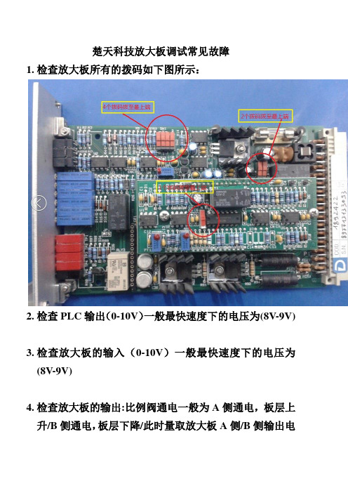
楚天科技放大板调试常见故障1.检查放大板所有的拨码如下图所示:2.检查PLC输出(0-10V)一般最快速度下的电压为(8V-9V)3.检查放大板的输入(0-10V)一般最快速度下的电压为(8V-9V)4.检查放大板的输出:比例阀通电一般为A侧通电,板层上升/B侧通电,板层下降/此时量取放大板A侧/B侧输出电流是多少,电磁阀最大工作电流为1.88A,1V=1I 此时板层运动最快的时候测得的电压应为1.88V慢速一般取1.2-0.75-0.45-0V可变,根据PLC输入的电压及放大板的最大电流/偏置电流来相互调整。
5.上升太慢,可调整A侧最大电流得到一个满意速度为止,最大为1.88V。
可以用电压表一边测一边上升一边调整。
6.下降太慢,可调整B侧最大电流得到一个满意速度为止,最大为1.88V。
可以用电压表一边测一边下降一边调整。
7.加载模式下即(自动模式)时按上升按钮,(A侧通电)板层上升停止后上下窜动,此时应将B侧的最大电流往小调整直至板层停止。
加载模式下,按上升按钮,(A侧通电)使能信号停止板层不停止,继续上升,此时应把A 侧的最大电流往小调整,直至停止。
加载模式下下降调整与上升调整相反。
8.上升定位不精准,减速不明显,可调整A侧偏置电流得到一个满意值为止,可以用电压表一边测一边上升一边调整,一般以1圈为一个单位。
9.下降定位不精准,减速不明显,可调整B侧偏置电流得到一个满意值为止,可以用电压表一边测一边下降一边调整一般以1圈为一个单位。
10.备注:按上述方式操作的前提是PLC输出为电压(0-10V)A侧通电为板层上升,B侧通电为板层下降。
10.。
MAX20048评估板说明书

MAX20048EVKIT#Evaluates: MAX20048 MAX20048 Evaluation KitGeneral DescriptionThe MAX20048 evaluation kit (EV kit) is a fully assembled and tested application circuit for the MAX20048 current-mode buck-boost controller IC. The EV kit is designed to deliver up to 16A (max) input current with input voltages from 2V to 36V. The output-voltage accuracy is ±2% within the normal 9V to 18V operation input range and a ±3% accuracy in the 2V to 18V range. Voltage quality can be monitored by observing the PGOOD signal.The IC offers 5V fixed output voltage and a 4V to 25V OUT programmable range. Switching frequency is adjustable from 220kHz to 2.2MHz, which allows for small external components, reduced output ripple, and guarantees no AM interference. The IC automatically enters skip mode at light loads with low 55µA quiescent current at no load. The IC comes with a spread-spectrum frequency-modulation option designed to minimize EMI-radiated emissions and a SYNCOUT option that outputs 180° out-of-phase clock. Benefits and Features●2V to 36V Input Supply Range●Delivers Up to 16A Input Current●Enable Input●Frequency Synchronization Input●Voltage-Monitoring PGOOD Output●BIAS Voltage-Monitoring Test Point●Fully Assembled and Tested●Proven PCB LayoutOrdering Information appears at end of data sheet.Quick StartRequired Equipment●MAX20048 EV kit●2V to 36V, 20A power supply capable of providing20A at 2V input●Voltmeter●Electronic loadProcedureThe MAX20048 EV kit is fully assembled and tested. Follow the steps below to verify board operation:1)Verify that all jumpers are in their defaultpositions, as shown in Table 1.2)Connect the positive and negative terminals of thepower supply to IN and GND test pads, respectively.3)Set the power-supply voltage to 14V and 10A currentlimit.4)Connect the positive terminal of the voltmeter to OUTand the negative terminal to GND2.5)Turn on the power supply.6)Verify that OUT is approximately 12V.Additional Evaluation7)Connect the positive terminal of the electronic load toOUT and the negative terminal to GND2.8)Set the electronic load to 2A and turn on the load.9)Verify output voltage on the voltmeter is 12V ±2%.10)With the load still on, slowly reduce the input voltagefrom 14V to 8V. Verify output voltage on the voltmeter is 12V ±2%Table 1. Default Jumper SettingsJUMPER DEFAULT SHUNTPOSITION FUNCTIONS EN ON-Middle Buck-boost enabled PGOOD PU InstalledPGOOD pulls up toVBIAS when OUT isin regulationSYNC FPWM-Middle Forced-PWM modeClick here for production status of specific part numbers.Evaluates: MAX20048 MAX20048 Evaluation KitDetailed Description of HardwareThe MAX20048 EV kit provides a proven layout for the MAX20048 buck-boost controller IC. The IC accepts input voltage as high as 36V and can deliver high-load currents, with a 20A (max) input current in boost mode. The EV kit can handle an input-supply transient up to 40V. Various test points are included for evaluation. The EV kit comes installed with a 3mΩ current-sense resistor on the input (R1) and a 4mΩ sense resistor on the output (R2). This sets the input current limit to 16.67A and the runaway current limit to 18.75A. A higher current limit can be set by changing the sense resistors. An optional filter input (IN_FILTER) is provided to test designs with an additional input filter. The default EV kit comes with no filter installed, so input terminal IN must be used.External SynchronizationThe IC can operate in fixed-PWM (FPWM) mode or skip mode. The EV kit comes with a default jumper setting of FPWM. T o enable skip mode operation, change the jumper to Skip-Middle. The IC can be synchronized to an external clock by connecting the external clock between the middle and ground pins on the SYNC jumper. The IC is forced to operate in FPWM mode when SYNC is connected to a clock source.Output Monitoring (PGOOD)The EV kit provides a power-good output test point (PGOOD) to monitor the status of the buck output (OUT). PGOOD is an open-drain output and is high impedance when the output voltage is in regulation. PGOOD is low impedance when the output voltage drops below 92% (typ) of its nominal regulated voltage. To obtain a logic signal, pull up PGOOD to BIAS by installing a shunt on the PGOOD jumper.Evaluating Other VoltagesThe EV kit comes installed with the MAX20048ATGCA/ VY+ and is configured for 12V OUT at a 420kHz switching frequency set for 16A (max) input current in boost mode. For evaluating other configurations, refer to the Design Example table in the MAX20048 IC data sheet. Other IC options for spread spectrum/SYNCOUT can be installed as well.EMC PerformanceEV kit provides a proven layout that is compliant with CISPR-25 requirements for EMC testing. The default EV kit (12V OUT, 420kHz configuration, without spread spectrum) requires no additional filtering to meet the CISPR-25 EMC standards. The IC also comes with the spread-spectrum option, which can be ordered to improve EMC performance.Specifications Summary●V IN (min): 2V●V IN (max): 36V●V OUT: 12V●f SW: 420kHz●I OUT (max): 5A●Input Current: 16.67A peak current●Runaway Current: 18.75A peak current●SPS: Off●FSYNC: Jumper set to PWM (default)#Denotes RoHS-compliant.PART TYPEMAX20048EVKIT#12V Output/420kHz EV kit Ordering InformationEvaluates: MAX20048MAX20048 Evaluation Kit REF DES QTY MFG PART #MANUFACTURERDESCRIPTIONC1, C2, C33CGA6P3X7S1H106M TDK CAP CER 10UF 50V X7S 1210C41EEH-ZE1H680PPanasonic CAP ALUM POLY 68UF 20% 50V SMDC5, C6, C173CGA2B3X7R1H104M050BB TDK CAP CER 0.1UF 50V X7R 0402C71CGA4J1X7R1V475K125AE TDK CAP CER 4.7UF 35V X7R 0805C81CGA2B2X7R1E103K050BA TDK CAP CER 10000PF 25V X7R 0402C91C0402C101K4RACAUTOKEMET CAP CER SMD 0402 100PF 10% X7R 1L20----Do Not InstallC10, C11, C153CAA572X7R1V107M TDK CAP CER 100uF, 35V, 2220, X7R C12, C13, C143CGA3E3X7R1H474K080AE TDK CAP CER 0.47UF 50V X7R 0603C161CGA4J1X7R1V225M125ACTDK CAP CER 2.2UF 35V X7R 0805C18, C192----Do Not InstallD11BAT54AWFILMY ST MicroelectronicsDIODE ARRAY SCHOTTKY 40V SOT323L11XAL1060-222E Coilcraft Inductor, 2.2uHR11PMR18EZPFV3L00ROHM RES 0.003 OHM 1% 1W 1206R21PMR18EZPFV4L00ROHM RES 0.004 OHM 1% 1W 1206R31ERJ-2GEJ473X Panasonic RES SMD 47K OHM 5% 1/10W 0402R51ERA-2AEB7322X Panasonic RES SMD 73.2K OHM 5% 1/10W 0402R6, R102ERA-2AED103X Panasonic RES SMD 10K OHM 0.5% 1/16W 0402R11, R14, R15, R164ERJ-2GEJ2R0X Panasonic RES SMD 2 OHM 5% 1/10W 0402R7, R12, R133RC0402JR-070RL Yageo RES SMD 0 OHM JUMPER 1/16W 0402R81ERJ-2GEJ200X Panasonic RES SMD 20 OHM 5% 1/10W 0402R91ERA-2AEB8662X Panasonic RES SMD 86.6KOHM 0.1% 1/16W 0402R171RC0603JR-0710KLYageo RES SMD 10K OHM 5% 1/10W 0603R41----Do Not Install R18, R19, R20, R214----Do Not InstallU11MAX20048ATGA/VY+Maxim Integrated Automotive 40V, 55uA Iq, 2.2MHz, H-BridgeBuck-Boost ControllerQ1, Q2, Q3, Q44NVMFS5C460NLON Semiconductor MOSFET N-CH 40V 21A 78A 5DFN IN_FILTER, IN, OUT, GND,GND2, GND365020Keystone Electronics TEST POINT PC LOW PRO W/OUT BASE FBR, PGOOD, VCC 35012Keystone ElectronicsTEST POINT PC MULTI PURPOSE WHT ENABLE, SYNC2PEC03SAAN Sullins CONN HEADER .100 SINGL STR 3POS J41PEC02SAANSullinsCONN HEADER .100 SINGL STR 2POSMAX20048 EVKIT BOMMAX20048 EV Kit Bill of MaterialsEvaluates: MAX20048 MAX20048 Evaluation KitMAX20048 EV Kit SchematicMAX20048 EV Kit Component Placement Guide―TopEvaluates: MAX20048 MAX20048 Evaluation KitREVISION NUMBER REVISIONDATE DESCRIPTIONPAGESCHANGED07/18Initial release—Revision HistoryFor pricing, delivery, and ordering information, please contact Maxim Direct at 1-888-629-4642, or visit Maxim Integrated’s website at .MAX20048EVKIT#。
MD-1系列比例放大板说明书完整版

MD-1系列比例放大板说明书MD-1系列比例放大板的用途是向各类电液比例阀提供所需要的直流电源。
它能按输入电压的大小成比例地控制输出电流,电路原理属脉宽调制型,具有发热小、功耗低、寿命长、可靠性高的特点。
(注意:MD-1比例放大板使用前必须进行正确预调,否则,有可能使它不能可靠工作)MD-1系列比例放大板按输出直流电流配有三种规格:MD-1型电流I0=0~0.8A;MD-2型电流I0=0~2.5A;MD-3型电流I0=0~5A。
输入控制信号电压均为V m=0~5VDC(PLC输出电压信号,不得超出9V)。
MD-1系列比例放大板接线端子及元件布置如图示:图中A区为接线端子:PS+(3)—24VDC正输入端子;PS-(4)—24VDC负输入端子;LD+(1)—比例阀电磁铁绕组正端;LD-(2)—比例阀电磁铁绕组负端;V CC(5)—直流+9V输出端子(对GND),可作控制信号使用;GND(6)—控制信号的参考地;P in1(7)和P in2(8)—控制信号的输入端子(对GND)。
使用两位数并联数码盘调节输入信号时,P in1和P in2应分别接入;其它情况,可任意选用P in1和P in2 ,接线时应绝对避免GND端与PS一端相连,否则,将烧坏比例放大板。
图中B区位调整电位器:P1(M)—增益调整(用于满量程定标,逆时针减小,出厂为最大状态);P2(↑)—输出电流上升斜率调节(出厂最快状态,逆时针减慢);P3(↓)—输出电流下降斜率调节(出厂最快状态,逆时针减慢);P4(0)—输出电流初值调节(出厂为零电流状态)。
图中C区为显示二极管:二极管点亮显示DC24V供电及DC9V控制电源正常工作。
其预调方法有下列二种:1、电位器输入信号法¢1.1按上述布置图正确接线,通入24V电压(必须接入电流表)。
1.2将电位器W转至最小,调节电位器P4,可获得初始电流值。
1.3慢慢转动电位器W,使电流表读数为1A,再逆时针转动电位器P1,使电流表读数为0.8A。
[说明]注塑机比例流量、压力的调校
![[说明]注塑机比例流量、压力的调校](https://img.taocdn.com/s3/m/3c8f930211661ed9ad51f01dc281e53a58025184.png)
[说明]注塑机比例流量、压力的调校[说明]注塑机比例流量、压力的调校比例流量、压力的调校1、比例阀与电子放大板比例流量阀和比例压力阀统称比例阀。
它有阀体和油摯线圈组成。
它的主要作用是通过油摯线圈受电的大小来控制阀的流量开放多少。
而油摯线圈受电和阀体流量开放程度是按一定比例线性关系而变化的。
当注塑机注塑预置叁数后,通过CPU中央处理器的处理和电子放大板的处理后,注塑机的注塑工作压力和流量就由比例阀控制。
具体可以用电箱旁的DPCA和DSCA电流表来显示比例线性关系。
具体叁数如下。
当S=00时,比例流量DSCA电流电流表显示200Ma;当S=99时,比例流量阀在DSCA表上显示680Ma当P=00时,比例压力阀在CPCA表上显示0mA;当P=99时,比例压力阀在DPCA表上显示800Ma。
而相对的压力表在15~145kg/CM2范围内呈现性变化。
DSCA电流表上和DPCA电流表上显示的电流叁数也就是比例流量、比例压力油摯阀线圈电压变化索取的。
它受控于电脑CPU中央处理器和电子放大板控制。
电子放大板输出电压控制比例流量、比例压力阀。
控制比例流量、比例压力阀的线圈吸合程度来控制油压和油流量。
2、比例阀与电脑CPU中央处理单元比例阀与电脑CPU中央处理单元是紧密相连,密切相连,共为一体,共同来完成注塑工作。
其运行过程应当为:叁数预置——>电脑处理——>电子放大板——>比例流量——>注塑各动作。
了解比例阀与电脑CPU中央处理单元的关系,对维修工作提供依据。
预置叁数使得数据进入电脑CPU中央处理单元,经过对叁数的运算和处理,将数据量通过D/A变换器转换成模拟量信号。
而该模拟量信号又经比例放大处理后,输出再通压力、流量最高控制和压力、流量最低限额控制4电位器进行控制调校,输出信号的幅值实际中应在0~3V范围内变化。
在维修过程中,一般调校好后才可以上机工作,不宜调节压力最高限额控制电位器,否则会改变工作点,给下一级控制带来困难。
VT-VSPA2 放大板样本
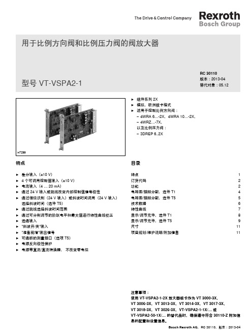
Bosch Rexroth AG ,RC 30110,版本:2013-04目录特点 1订货代码 2功能2电路图/插脚分配,选件 T1 4电路图/插脚分配,选件 T5 5技术数据 6特性曲线7显示/调节元件,选件 T1 8显示/调节元件,选件 T5 9尺寸11项目规划/维护说明/附加信息11特点▶差分输入(±10 V)▶ 4 个可调用控制值输入(±10 V) ▶电流输入(4 … 20 mA)▶通过 24 V 输入或跳线改变内部控制值信号极性▶通过相位识别(24 V 输入)或斜坡时间调用(24 V 输入)选择斜坡时间(选件 T5) ▶通过跳线选择斜坡时间范围▶通过可分别调节的阶跃电平和最大值进行特性曲线校正 ▶选通输入 ▶"斜坡开/关"输入 ▶"准备就绪"输出信号▶可通断的测量插口(选项 T5) ▶电源反向极性保护▶电源带直流/直流转换器, 不改变零电位H7299用于比例方向阀和比例压力阀的阀放大器▶组件系列 2X ▶模拟,欧洲板卡格式 ▶适用于控制比例方向阀:– 4WRA 6…-2X,4WRA 10…-2X,– 4WRZ…-7X,以及比例压力阀:– 3DREP 6..2XRC 30110版本:2013-04替代对象:05.12型号 VT-VSPA2-1注意事项:使用 VT-VSPA2-1-2X 放大器板卡作为 VT 3000-3X,VT 3006-3X,VT 3013-3X,VT 3014-3X,VT 3017-3X,VT 3018-3X,VT 3026-3X,VT-VSPA2-1-1X/… 或VT-VSPA2-50-1X/… 的替代品时,确保遵守符合 30110-Z 附加信息的配置和设置信息。
2/12VT-VSPA2-1 | 阀放大器Bosch Rexroth AG ,RC 30110,版本:2013-04订货代码01用于比例方向阀和比例压力阀的阀放大器,模拟,欧洲板卡格式VT-VSPA202用于控制比例方向阀 4WRA 6…-2X,4WRA 10…-2X 和 4WRZ…-7X 以及比例压力阀 3DREP 6..2X 103组件系列 20 至 29(20 至 29:技术数据和插脚分配不变)2X 04型号:标准V005选项:对于一个斜坡时间T1选项:对于五个斜坡时间T506明文形式的更多详细信息*010203040506VT-VSPA2–1–2X /V0//*功能开放式板卡插槽 VT 3002-1-2X/48F(请参阅样本 29928)附件供电设备 [1]放大器板卡随附了带接通电流限制器的供电设备。
液压站比例放大板说明书(中文版)

1/8模拟放大器类型 VT-VRPA1-50 至 VT-VRPA1-521X 系列RC 30117/07.06替代对象:05.06目录内容 页码特点 1订货代码 2功能说明2 - 3电路框图/插脚分配 4技术数据 5 - 6单元尺寸 6指示/调节元件7工程/维护注意事项/补充信息8特点– 适用于控制带有电气位置反馈的先导式比例流量控制阀(节流阀),类型 FE(规格 16 和 25)和 FES(规格 25 至 63)– 在插头方面,兼容放大器类型 VT 5011,VT 5012 和 VT 5062 至 VT 5066(视阀类型和规格而定)– 带可提高零电位的供电设备– 控制值信号输入:• 0 至 +6 V;0 至 +9 V;0 至 +10 V • 0 至 20 mA;4 至 20 mA(跳线)– 前面板上用于实现零电位和振幅衰减的电位计调节 – 斜坡时间的测量插口– 选通输入和"斜坡关闭"输入– 用于将最大斜坡时间从 0.02 s 更改至 5 s 或从 0.2 s 更改至 50 s 的跳线– 用于调整阀类型和规格的跳线– 控制值(0 至 +6 V)和实际值(0 至 –6 V)的输出– LED 指示灯"准备就绪"– 反向极性保护H6197_d订货代码用于带电气位置反馈的比例阀的模拟放大器,带1 个输出级用于以下比例流量控制阀(节流阀)的放大器:– 类型 FE 16,FE 25 和 FES 25(各类型均自系列 2X 起) = 50– 类型 FES 32 和 FES 40(各类型均自系列 3X 起) = 51– 类型 FES 50 和 FES 63(各类型均自系列 3X 起) = 52明文形式的更多详细信息1X =10 至 19 系列(10 至 19:技术数据和插脚分配不变)VT-VRPA11X*订购用于机架安装的 VT 5011,VT 5012 和 VT 5062 至 VT 5066 放大器备件时,盲板 4TE/3HE 必须单独订购。
比例放大板实验调试报告(VT-3013(3014)放大板)

比例放大板实验调试报告VT-3013(3014)BS30型一、实验目的:1、DA模块接线。
2、比例放大板接线。
3、比例放大板输出电流检测。
(1)电流表或万用表接电阻(40W,20Ω)串接进电路直接测输出电流。
注:比例放大板是恒流源,必须串接电阻,否则会烧坏万用表。
(2)测量DA模块差动电压(16A,16C)再换算。
(3)测试孔BU2,BU3用直流电压档测,约等于电流值。
4、组态。
5、电位器及电位器型传感器调整比例阀板电流。
6、拉绳传感器及AD模块接线。
二、实验原理:1、D/A模块:模拟信号与数字信号的转换模块。
(AD模块将模拟信号转成数字信号,DA模块是将数字信号转成模拟信号)2、放大板工作原理就是几级放大,把弱的模拟信号放大几百倍后再输出,是按比例放大的,就是输入信号×放大倍数=输出信号。
3、PLC加DA转换模块,就是把PLC内的数字量转化成模拟量,变成0-10V电压,而比例阀是可以接受模拟的电压电流信号的,但是与PLC的DA模块输出的电压、电流信号可能不一致,所以需要一个中间放大环节,把PLC的D/A模块输出的信号放大成比例阀能接受的电压或电流信号。
4、实验台系统采用24v开关电源供电,根据比例阀的输出特性,选择电流表、功率表等作为测量工具。
使用PC机作为上位机,读取模拟量模块数值、编写调试程序。
三、实验器材四、具体接线步骤:(一)比例放大板接线:(1)比例电磁铁线圈A两端分别接30A和24A;两端可以互换。
(30a,+V)比例电磁铁线圈B两端分别接28A和22A;两端可以互换。
(28a,+V)(2)比例控制器需直流24V供电电源正极接32A(或32C);电源负极接26A(或26C);本控制器需单独使用电源,不能与其他用电元件共用一个电源。
(二)可编程控制器(PLC)、DA模块接线函数发生器(此处为DA模块)等给出±10V差动电压从16A,16C两端输入正电压控制电磁铁B,负电压控制电磁铁A。
ATOS放大板调试说明

比例放大板调试指导
T he Debugging Roution of ATOS proportional amplifier
该调试说明以盘刹使用的放大板为例.对于猫头扭矩限制使用的放大板,调节方法相同.
1.调试工具:
数字式万用表一只,一字螺丝刀一把.
2.最大输出电压的调节
a)将万用表调整到直流电压检测挡(DC),再把万用表正极表笔接
触到a26号端子,负极表笔接触到a28号端子,如图
b)观察万用表上是否有电压值,如果有,用螺丝刀调节放大板S1
死区调整旋钮,使得万用表上显示电压为0V。
c)拉动盘刹制动手柄到最大位置, 观察万用表上电压值.通过S1
调节增益调整旋钮使得万用表读数为10VDC.
3.最大输出电流调节
a)将万用表调整到直流电压检测挡,再把万用表正极表笔插
入到前面板的电流输出正极孔内,负极表笔插入到负
极孔内.
b)拉动盘刹制动手柄到最大位置, 观察万用表上电压值.通过
调节S1增益调整旋钮使得万用表读数为2.1V.此时对
应放大板最大输出电流2.1A.
3.上升及下降斜坡设定(默认设置即可).
宏天公司技术部
2011.4.19。
- 1、下载文档前请自行甄别文档内容的完整性,平台不提供额外的编辑、内容补充、找答案等附加服务。
- 2、"仅部分预览"的文档,不可在线预览部分如存在完整性等问题,可反馈申请退款(可完整预览的文档不适用该条件!)。
- 3、如文档侵犯您的权益,请联系客服反馈,我们会尽快为您处理(人工客服工作时间:9:00-18:30)。
6.3 Adjusting the amplifier card
Working steps
You should adhere to the following sequence: Plug jumpers
Install card
Adjust command values
Adjust command value zero point
± 100 % = ± 10 V
Rectangular signal ±15V 10 mV to 10 V 10 mV to 10 V 10 mV to 10 V 10 mV to 10 V 10 mV to 10 V 10 mV to 10 V
22
RE 30110-B/08.04
Commissioning the amplifier card
ternal command value is available
Option VT-.../T1 Proceeding: Precondition: No command value call-up may be activated. ➤ Set external command value selection to 0 V. ➤ Set the internal command value to 0 V using potentiometer “Zw“. Check the setting at measuring socket “w“.
Option VT-.../T5 Proceeding: ➤ Select the command value to be adjusted (1, 2, 3 or 4) by means of a call-up signal (command value call-up 1 to 4). ➤ Turn the measuring point selector switch to the command value to be adjusted (switch position 1, 2, 3 or 4 = command value call-up 1 to 4). ➤ Use the associated potentiometer “w1“ .. "w4“ (or the connected external potentiometer) to set the desired command value. Check the setting at measuring socket “v“. ✔ Now, you can adjust the next command value.
Option VT-.../T5 Proceeding: Precondition: No command value call-up may be activated. ➤ Set external command value selection to 0 V. ➤ Set measuring point selector switch to “6” ➤ Set the internal command value to 0 V using potentiometer “Zw“. Check the setting at measuring socket “v“.
RE 30110-B/08.04
19
Commissioning the amplifier card
6.2 Adjustment and indicator elements
Fig. 6.1: Adjustment and indicator elements of amplifier card VT-VRPA2../T1
RE 30110-B/08.04
21
Commissioning the amplifier card
Measuring point Internal command value Command value call-up 1 Command value call-up 2 Command value call-up 3 Command value call-up 4 Zero point offset “Zw“ 1 summation signal of command values Ramp output signal Free Clock frequency Ramp time “t1” Ramp time “t2” Ramp time “t3” Ramp time “t4” Ramp time “t5” Current ramp time “t”
mand value ± 100 % = ± 10 V
Actual value
± 100 % = ± 2.5 V
Moreover, a measuring socket (t) is provided for adjusting the ramp time. The measuring voltage range is between 10 mV and 10 V.
If you change the setting of the sealed potentiometers (“ramp time symmetry“ and “internal reference voltage“) warranty claims become void!
Before installing the card, make sure that all jumpers on the amplifier card are plugged correctly.
For taking measurements, use only measuring instruments having an internal resistance of (Ri) > 100 kΩ.
For adjusting the potentiometers and for changing the measuring point selector switch (VT-.../T5) over, use a screw driver with a blade width of 4 mm.
In addition, a measuring socket (v) is provided for adjusting the command values and the ramp times and for checking further internal signals. The measuring points can be selected by means of the measuring point selector switch on the front panel. The signal of the measuring socket (v) is additionally fed to the male connector.
Adjust the command value
Option VT-.../T1 Proceeding: ➤ Select the command value to be adjusted (1, 2, 3 or 4) by means of a call-up signal (command value call-ups 1 to 4). ➤ Use the associated potentiometer "w1“ .. "w4“ (or the connected external potentiometer) to set the desired command value. Check the setting at measuring socket “w“. ✔ Now, you can adjust the next command value.
Measuring sockets g sockets for the command value (w) and the actual current
value (I) are provided on the front panel. The following is valid: Com-
Adjust ramp times (internal/external)
Adjust jump height
Adjust maximum values
Before you can start with the adjustment word, the system-specific connections must have been made.
Plug jumpers
Plug jumpers “J1“ to “J10“ according to the application at hand so that the associated bridge is either open or closed. Information about the settings can be found in Fig. 6.1 on page 20 (for option T1) or in Fig. 6.2 on page 21 (for option T5).
20
RE 30110-B/08.04
Commissioning the amplifier card
Fig. 6.2: Adjustment and indicator elements of amplifier card VT-VRPA2../T5
Masuring sockets
A measuring sockets for the command value (w) and the actual current value (I) is provided on the front panel. The following is valid: Command value measuring socket: ± 100 % = ± 10 V Actual value measuring socket: ± 100 % = ± 2.5 V