海尔 EC8003-YT1说明书 2017
海尔家用电器产品说明书.pdf_1719182771.4172356

This is the safety alert symbol. It is used to alert you topotential personal injury hazards. Obey all safety messagesthat follow this symbol to avoid possible injury or death.Indicates a hazardous situation which, if not avoided,will result in death or serious injury.Indicates a hazardous situation which, if not avoided,could result in death or serious injury.Indicates a hazardous situation which, if not avoided,could result in minor or moderate injury.Addresses practices not related to personal injury.Read all safety warnings and instructions.Failure to follow the warnings and instructions may result in serious injury.Save all warnings and instructions for future reference.The warnings and precautions discussed in this manual cannot cover allpossible conditions and situations that may occur. It must be understoodby the operator that common sense and caution are factors which cannotbe built into this product, but must be supplied by the operator.Work area1.Turn off the engine,set the parking brake, and block thetires before working on a vehicle. 2.Keep the work area clean andwell lighted. Cluttered benchesand dark areas increase therisk of injury to persons.3.Keep bystanders and children awaywhile operating the tool. Distractionscan result in loss of control of the tool.Page 2For technical questions, please call 1-800-444-3353.Items 44899, 44900Personal safety1.Stay alert. Watch what youare doing and use commonsense when operating the tool.Do not use the tool while tiredor under the influence of drugs,alcohol, or medication.A momentof inattention while operating the toolincreases the risk of injury to persons.2.Dress properly. Do not wear looseclothing or jewelry. Contain long hair.Keep hair, clothing, and glovesaway from moving parts.Loose clothes, jewelry, or long hairincreases the risk of injury to persons asa result of being caught in moving parts.e safety equipment.Wear ANSI-approved safety gogglesand heavy-duty work gloves during use.Tool use and care1.Do not force the tool. Use the correcttool for the application. The correcttool will do the job better and safer atthe rate for which the tool is designed.2.Store the tool when it is idle out ofreach of children and other untrained persons. A tool is dangerous inthe hands of untrained users.3.Check for misalignment or bindingof moving parts, breakage ofparts, and any other conditionthat affects the tool’s operation.If damaged, have the tool servicedbefore using. Many accidents arecaused by poorly maintained tools.e only accessories that areidentified by the manufacturerfor the specific tool model.Use of an accessory not intendedfor use with the specific tool model,increases the risk of injury to persons.5.Avoid off-center loads. If the Pumpseems unusually hard to operate,immediately stop. Adjust the Ram toeliminate or diminish an off-off center load.The Flange Base and Flange Headmust only be used together toprevent an off-center load.6.Protect the Hose. Do not dropheavy objects on the Hose.Avoid kinks in the Hose.Maintain proper clearance to avoiddamage to the Hose and Couplers.7.Inspect repair before using vehicle.Repairs to structural or frame membersmust be inspected by a qualifiedtechnician to ensure that thestructure is still strong enoughto safely fulfill its function.Service1.Tool service must be performedonly by qualified repair personnel.2.When servicing a tool, use onlyidentical replacement parts.Use only authorized parts.SAVE THESE INSTRUCTIONS.Page 3 For technical questions, please call 1-800-444-3353.Items 44899, 44900Model4489944900Ram Capacity 4 Tons2 Tons w/ extensions10 Tons5 Tons w/ extensionsRam Travel5″6″Extension Pole Length4′ 512⁄″ Maximum5′ MaximumSpreader Capacity 12⁄ Ton3-34⁄″ Maximum Opening12⁄ Ton3-34⁄″ Maximum OpeningHose Length6′6′Read the ENTIRE IMPORTANT SAFETY INFORMATION section at thebeginning of this document including all text under subheadings thereinbefore set up or use of this product.Ram Attachments1.The ns connect in differentExtensionscombinations to reach desired lengths.2.The tor is used to connectMale Connectorthe female end of the Ram to a Base.3.The Flat Base is used on the stationaryside to spread out the force of the Ram.4.The 90° V Base is used to offset theforce of the Ram when there is not astraight line between the stationaryside and the damaged side, orto spread out force on curved surfaces.5.The ad is used on theCap Headpushing end to prevent slipping.6.The ad is used for poppingRubber Headdents out of sheet metal such asdoors or body panels and to minimizedamage to the work surface.7.The ad is used to repairWedge Headsmall dents and areas locatedin angles and tight spaces.8.The Flange Base and Flange Headare used together to allow spreadingin areas that the Ram cannot fit into. Note: The Flange Base andFlange Head must only be used together to prevent an off-center load.Page 4For technical questions, please call 1-800-444-3353.Items 44899, 44900Page 5For technical questions, please call 1-800-444-3353.Items 44899, 44900Ram SetupNote:When positioning the Ram use a smaller attachment on the side that is to be bent instead of the stationary side. If the stationary side is indanger of being bent or damaged, place a block of wood or other materialbehind the Flat Base to distribute pressure over a greater area.1.Clean the end of the Hose and theinlet on the Ram. Unscrew andsave the End Plugs located onthe end of the Hose and Ram.2.Attach the Hose to the Ram.3.Assemble attachments as shown below:Male Connector Ram 90° V Base or Flat Base (install Extensions here as needed)Cap Head,Rubber Head,or Wedge Head Ram Flange Base (install Extensions here as needed)Flange Head Note: If using the Flange Base and Flange Head, thread the Flange Baseonto the Ram completely andalign the Flange Head to it.Spreader SetupThe der is used when the RamSpreader is too long to fit between the stationaryside and the damaged area.1.Clean the end of the Hose and the inlet on the Spreader.2.Unscrew and save theEnd Plugs located on the endof the Hose and Spreader. 3.Attach the Hose to the Spreader, as shown below:PumpSpreaderHoseRead the ENTIRE IMPORTANT SAFETY INFORMATIONsection at the beginning of this manual including all textunder subheadings therein before use of this product. 1.Check the Hydraulic Fluid level, following the instructionsin the Cleaning and Maintenance section.2.Determine which direction the frame needs to be bent.3.Remove any obstructions that could be damaged or are in the way. Note: When using the Pump in a vertical position,keep the Hose end of the Pump downward.ING RAM:a.Connect the appropriate Base tothe stationary side of the Ram,and connect the appropriate headto the pushing end of the Ram. Note: When repairing larger bodypanel dents such as a dented door,fender or quarter-panel use theRubber Head on the pushing end.b.If using the Flange Base orFlange Head:Thread the Flange Base onto theRam completely and align theFlange Head to it. The Flange Baseand Flange Head must only be usedtogether to prevent off-center load.c.Position the Ram so that the Baseis resting against a frame memberopposite the damaged area. It mustalso be in line with the direction inwhich the damaged area needs tobe pushed. The vehicle body partmust be stronger than the areato be bent or it may be damaged.A block of wood or a towel maybe used to protect the body part.d.Aim the pushing end towards thearea that needs to be repaired, andslowly apply pressure with the Pump. Note: To prevent damage,do not overextend the Ram.ING SPREADER:a.Place the Spreader so that thehinged (pushing) arm is restingagainst the part to be movedand the stationary arm is resting against a non-movable base.b.Carefully hold the Spreader inposition and apply pressurewith the Pump.5.Once both ends have made contact, move as far away as possible and continue toslowly apply pressure to the damaged area until the desired bend has been made.CAUTION! Keep hands away from contact areas and tight spaces.The tool may slip and cause injury.6.When the damaged area has been bent to the desired position,slowly turn the Release Valve counterclockwise to release thehydraulic pressure and remove the Ram or Spreader.7.Clean all hydraulic ports and cover them with clean End Plugs.Page 6For technical questions, please call 1-800-444-3353.Items 44899, 449001.Keep the surface of this tool and itsaccessories free of hydraulic fluid andgrease. Use only a mild detergent anddamp cloth when cleaning. Do not usea flammable or combustible solventto clean this tool or its accessories.2.Before each use, examine the generalcondition of the tool and its accessories.Check for loose components,misalignment, binding of moving parts,broken parts and any other conditionthat may affect its safe operation.Do not use a damaged tool orits damaged accessories.3.Keep hydraulic connections clean.Clean all hydraulic ports and replaceDust Covers immediately after use.4.Store the Pump with theRelease Valve open.Filling and Bleeding Hydraulic FluidIf the Pump operation feels spongy, or the Ram lowers while the Release Valve is closed, there may be air in the Pump. Bleed the Pump as follows:1.Set Pump flat on a level surface.2.Remove the Fill Screw.The Seal Ring should come off with it.3.The fluid level should be nearthe bottom of the opening.If required,add high gradehydraulic fluid.4.Make sure the Seal Ring is still inplace around the Fill Screw andthread the Fill Screw into the Pumpsecurely. Do not use thread seal tape.5.Firmly close the Release Valveby turning it clockwise.6.Press the tip of the Coupleragainst a hard surface andpump the pump handle.7.Continue pumping, until thehydraulic fluid coming out the end ofthe Coupler tip is free of air bubbles.8.Recheck the fluid level andadd fluid if necessary.9.Turn the Release Valvecounterclockwise to releasethe pressure in the Pump and Hose.Changing Hydraulic Fluid1.Change the hydraulic fluid yearly.2.Remove the Fill Screw and tilt thePump to drain out the old fluid.3.Refill the hydraulic fluid and bleedthe system several times to ensureall air is out of the system.Page 7For technical questions, please call 1-800-444-3353. Items 44899, 44900Page 8For technical questions, please call 1-800-444-3353.Items 44899, 4490044900 Main Parts List and Assembly Diagram Part Description Qty 3Pump Handle 14Hose 15Ram 16Pump 17Male Connector 18Flange Head 19Flange Base 110Wedge Head 11190° V Base 1Part Description Qty 12Flat Base 113Rubber Head 114Spreader 115Cap Head 1165″ Extension 11710″ Extension 11818″ Extension 11927″ Extension 1181651713147109151112843619PLEASE READ THE FOLLOWING CAREFULLYTHE MANUFACTURER AND/OR DISTRIBUTOR HAS PROVIDED THE PARTS LIST AND ASSEMBLY DIAGRAM IN THIS DOCUMENT AS A REFERENCE TOOL ONLY . NEITHER THE MANUFACTURER OR DISTRIBUTOR MAKES ANY REPRESENTATION OR WARRANTY OF ANY KIND TO THE BUYER THAT HE OR SHE IS QUALIFIED TO MAKE ANY REPAIRS TO THE PRODUCT, OR THAT HE OR SHE IS QUALIFIED TO REPLACE ANY PARTS OF THE PRODUCT. IN FACT, THE MANUFACTURER AND/OR DISTRIBUTOR EXPRESSLY STATES THAT ALL REPAIRS AND PARTS REPLACEMENTS SHOULD BE UNDERTAKEN BY CERTIFIED AND LICENSED TECHNICIANS, AND NOT BY THE BUYER. THE BUYER ASSUMES ALL RISK AND LIABILITY ARISING OUT OF HIS OR HER REPAIRS TO THE ORIGINAL PRODUCT OR REPLACEMENT PARTS THERETO, OR ARISING OUT OF HIS OR HER INSTALLATION OF REPLACEMENT PARTS THERETO.Page 9For technical questions, please call 1-800-444-3353.Items 44899, 44900Record Product’s Serial Number Here:Note: If product has no serial number, record month and year of purchase instead.Note: Some parts are listed and shown for illustration purposes only, and are notavailable individually as replacement parts.44900 Parts List and Assembly Diagram A - Ram (5)Part Description 1ADust Cap 2ACoupling 3ACoupling Ring 4AC Snap Ring 5ABushing 6A Protecting Cap 7A Ring 8A Screw 9ASpring 10AC Clip 11AWasher 12ASpreader 13ACap 14ACap 15ACap 16ABushing 17ABearing 18AWasher 19ARam 20A Cylinder 4A 18A 6A 7A 19A 17A16A15A13A14A13A12A 1A 20A8A 5A 9A10A 11A 2A3A8APage 10For technical questions, please call 1-800-444-3353.Items 44899, 4490044900 Parts List and Assembly Diagram B - Spreader (14)11B 10B 9B 12B 13B 8B 7B 6B 5B 4B 3B 2B 1B Part Description 1BDust Cap 2BO-ring 3BCoupler 4BCoupler Ring 5BEnd Plug 6BWasher 7B Cup Seal Part Description8B Piston 9B C-clip 10B Pivoting Pin 11B Pushing Arm 12B Spring 13B Stationary ArmPart Description 1C Screw (Safety Valve) 2C Plastic Cap3C Screw4C O-ring Seal5C Spring6C Stem7C Ball Valve8C Washer9C Valve10C Release Valve11C Spring12C Ball Valve13C Fill Screw14C Ball Valve Part Description15C End Plug16C Coupling17C Spring18C Hose19C Fluid Fitting20C Grip21C Handle22C Circle Clip23C Pivot Pin Arm24C Pivot Pin Arm25C Pivot Pin Arm26C Plunger27C Washer28C SealPart Description29C Filter Ring30C Cylinder31C Washer32C Seal33C Spacer34C O-ring35C O-ring36C Bolt37C Pump Foot38C Screw39C Reservoir40C Seal41C Filter42C Housing44900 Parts List and Assembly Diagram C - Pump20C38C 13C34C 42C1C7C6C4C3C2C25C22C27C29C9C37C32C30C28C26C18C24C8C5C39C36C35C41C40C14C33C10C11C12C17C31C19C15C16C21C23CPage 11 For technical questions, please call 1-800-444-3353.Items 44899, 4490044899 Main Parts List and Assembly Diagram13143816129110172 76541511Part Description Qty1Pump12Ram13Hose1419-1/2” Extension1516-1/2” Extension168-1/2” Extension175” Extension183-1/4” Extension19Cap Head1Part Description Qty10Spreader1112-3/4” Rubber Head112Wedge Head11390° V Base114Flange Head115Flange Base116Male Connector117Flat Base1Page 12For technical questions, please call 1-800-444-3353.Items 44899, 44900Page 13For technical questions, please call 1-800-444-3353.Items 44899, 4490044899 Parts List and Assembly Diagram A - Spreader (10)13A12A 10A11A9A8A 7A 6A 5A4A 3A 2A 1APartDescription 1A Dust Cap 2A O-ring 3A Coupler4A Coupler Ring 5A End Plug 6A Washer 7ACup SealPartDescription8A Piston9A Stationary Arm 10A C-clip 11A Spring12A Pivoting Pin 13APushing ArmPage 14For technical questions, please call 1-800-444-3353.Items 44899, 4490044899 Parts List and Assembly Diagram B - Ram (2)PartDescription1B End Plug 2B O-ring 3B Coupler4B Coupler Ring 5B Screw 6B Cylinder 7B Spring 8B Ring9B Protector Cap10B Circle Clip 11B Washer 12B “U” Seal13B Backup Ring 14B Bushing 15B Bearing 16B Ram 17B Washer 18B C-clip 19BBushing1B2B3B4B5B6B5B19B 7B8B9B10B11B12B13B14B15B16B17B18BPart Description 1C Screw (Safety Valve) 2C Plastic Cap3C Screw4C O-ring Seal5C Spring6C Stem7C Ball Valve8C Washer9C Valve10C Release Valve11C Spring12C Ball Valve13C Fill Screw14C Ball Valve Part Description15C End Plug16C Coupling17C Spring18C Hose19C Fluid Fitting20C Grip21C Handle22C Circle Clip23C Pivot Pin Arm24C Pivot Pin Arm25C Pivot Pin Arm26C Plunger27C Washer28C SealPart Description29C Filter Ring30C Cylinder31C Washer32C Seal33C Spacer34C O-ring35C O-ring36C Bolt37C Pump Foot38C Screw39C Reservoir40C Seal41C Filter42C Housing44899 Parts List and Assembly Diagram C - Pump20C38C 13C34C 42C1C7C6C4C3C2C25C22C27C29C9C37C32C30C28C26C18C24C8C5C39C36C35C41C40C14C33C10C11C12C17C31C19C15C16C21C23CPage 15 For technical questions, please call 1-800-444-3353.Items 44899, 44900Harbor Freight Tools Co. makes every effort to assure that its products meet high qualityand durability standards, and warrants to the original purchaser that this product is free from defects in materials and workmanship for the period of 90 days from the date of purchase.This warranty does not apply to damage due directly or indirectly, to misuse, abuse, negligence or accidents, repairs or alterations outside our facilities, criminal activity, improper installation, normal wear and tear, or to lack of maintenance. We shall in no event be liable for death, injuries to persons or property, or for incidental, contingent, special or consequential damages arising from the use of our product. Some states do not allow the exclusion or limitation of incidental or consequential damages, so the above limitation of exclusion may not apply to you. THIS WARRANTY IS EXPRESSLY IN LIEU OF ALL OTHER WARRANTIES, EXPRESS OR IMPLIED, INCLUDING THE WARRANTIES OF MERCHANTABILITY AND FITNESS.To take advantage of this warranty, the product or part must be returned to us with transportation charges prepaid. Proof of purchase date and an explanation of the complaint must accompany the merchandise. If our inspection verifies the defect, we will either repair or replacethe product at our election or we may elect to refund the purchase price if we cannot readily and quickly provide you with a replacement. We will return repaired products at our expense, but if we determine there is no defect, or that the defect resulted from causes not withinthe scope of our warranty, then you must bear the cost of returning the product.This warranty gives you specific legal rights and you may alsohave other rights which vary from state to state.3491 Mission Oaks Blvd. • PO Box 6009 • Camarillo, CA 93011 • (800) 444-3353。
海尔电子产品说明书.pdf_1718723447.38698

Power consumption Fuse Mains connection
9DH@ITDPITX@DBCU
Dimensions (H x B x T)
Weight
Japan 100 V~, 50 - 60 Hz
13 W -
external power supply
s Extensive MIDI implementation for control/automation of all MIDI functions
s BASS V-AMP: Adjustable stereo aux input for mixing line-level signals (e.g. CD player, sound card etc.)
BALANCED LINE OUT Output impedance Max. output level
HEADPHONES Max. output level
9DBDU6GÃPVUQVUT
XLR Output impedance Nom. output level
RCA Output impedance Nom. output level Format
1/4" TRS connector, unbalanced
+15 dBu/100 Ω (+23 dBm)
-
transformer-balanced
-
110 Ω
-
3,5 V peak-to-peak
-
not grounded, unbalanced
-
75 Ω
-
0,5 V peak-to-peak
海尔智能家居设备说明书

SC-899 Triple Timer-Stopwatch, Speed Timer and CountdownUse as a Single, Double or Triple Timer Operating Instructions ©MBI Corp.INTRODUCTIONThank you for purchasing the Robic SC-899—Triple Timer. Your purchase brings you a reliable, World-Class Timer which measures performance for a wide array of sports and many other activities. Please become familiar with its operation so you can enjoy its many fine features:●Time up to three (3) competitors at once...with a single timer…up to 540 memory recall! ●You can look at results in more ways than ever before with the Robic SC-899. ●Best of all, set it up exactly the way you want.●The SC-899 has three (3) fully loaded time keeping modes:1/ Chronograph (Stopwatch);2/ Speed Timer in mph or kph3/ Countdown Timer (Shows time remaining). You can choose from:●1, 2 or 3 competitors at once●Start the timers simultaneously (at the same time) or separately (at different times), it’s your option ●Select from Lap or Cum Split running times●180 Memory Recall of all 3 timers, Review each without leaving the stopwatch.●Use the memory while the timer is running, so you can immediately take another reading without changing modes.●View the memory recall in ascending (1, 2, 3…) or descending (…3, 2, 1) order ●1/100 second precision up to 60 minutes. Lap Counter to 999 readings.●Program up to three (3) countdown timers to operate independently or simultaneously, they can loop or sequence through each time or stop at the end of the preset time.●Speed timer in mph/kph…can be used at any speedway in the world…input distance to within 1/1000 of a mile or kilometer.●Fastest, Slowest and Average Lap time and /or speed●Each of the three timers takes up to 1000 readings, with Memory recall of the previous 180 readings. ●On-demand EL backlight for low light or no light use ●Water resistant design●Time of day, alarm, calendarSETTING THE TIME OF DAY &CALENDAR● In Time of Day, press and hold C for 3 seconds to enter time and date setting, Alarm hour flashes.●Press E to advance the value.●Press B to set to the next item, and press E to adjust the value. Setting sequence will be:Alarm hour>Alarm minute>Second>Hour>Minute>Month>Date>Weekday>12/24Hour format ●Press C at any time to exit the setting process.NOTE:The alarm will sound for 20 seconds. You may press any button to silence the alarm.NOTES ON OPERATING THE SPEED TIMER AND STOPWATCH●From Normal Time mode, press B , “Chrono ” displays for 2 seconds and stopwatch mode appears.●The stopwatch can display up to 999 time readings and will recall the last 180 times from memory.For example, if the current display is the 250th lap, then 71 to 250 laps are held in memory.The SC-899 has 1/100 second resolution for 60 minutes then 1 second up to 24 hours You may set up your SC-899 as a Single, Double or Triple Stopwatch. You may start all the Timers at the same time or separately. You may also select Lap or Split timing to appear. The processes are described below and also apply to the Speed Timer function.Each timer has a dedicated pushbutton which will Start and Stop as well as take intermediate time/speed readings. A is for Timer 1, D is for Timer 2 and E is for Timer 3.Should you select to use the SC-899 as a double or triple timer, it is recommended you use it in your hand a few different ways to determine how you feel most comfortable pushing the buttons.In Double and Triple Timer options, the last press to Stop the timer takes 2 seconds. Should you need to take your last reading (finish times) in short sequence, press the Pusher for each timer as if you were taking any reading. Then, after the finish, proceed to press each Pusher for > 2 seconds to stop the timer. Ignore the final reading when you are reviewing the memory.●In the Single timer option, you may switch modes by pressing B . While using double or Triple Timers, press and hold B > 2 seconds to change modes. The timer will continue to run.NOTE :The Speed Timer and Stopwatch modes will not operate simultaneously. To use the Stopwatch, the Speed Timer must be reset to all zeroes and Vice Versa for the Speed Timer Mode.USING THE SC-899 AS A DOUBLE OR TRIPLE STOPWATCHSet the stopwatch as CH-2 or CH-3.Use A to operate stopwatch #1, use D to operate stopwatch #2, and use E to operate stopwatch #3.For Dual timer, the top line displays stopwatch 1, middle line displays stopwatch 2, and bottom line displays time of stopwatch #1.USING THE STOPWATCH WITH "SEP" OPTION●SEP refers to starting the timers Separately:●In stopwatch mode with the timers stopped, press and hold A /D /E for 5 seconds to reset to all zeroes. ●Press A to start stopwatch #1, D to start #2 or E to start #3. RUN indicator appears.●Press A , D or E to take an intermediate time reading. The lap/split time and lap/split number appears. It remains displayed for 15 seconds after which the new running lap or Split time appears. You may also release the reading at any time by pressing B .After your final reading, Press and hold A , D or E for 2 seconds to stop the time. ●STOP indicator appears.●ALL refers to starting the timers Simultaneously:●In stopwatch mode with the timers stopped, press and hold A /D /E for 5 seconds to reset to all zeroes. ●Press A to start stopwatches #1, #2, and #3. RUN indicator appears.●Press A , D or E to take an intermediate time reading. The lap/split time and lap/split number appears. It remains displayed for 15 seconds after which the new running lap or Split time appears. You may also release the reading at any time by pressing B .After your final reading, Press and hold A , D or E for 2 seconds to stop the time. ●STOP indicator appears.You may access the Recall function at any time, whether the timer is running or stopped. To return to current timing and take a split, simply press the button associated with the timer TO TAKE A READING.Press C at any time to access the Memory recall. Continue to Press or Hold C to review the readings in this sequence:Fastest lap/split of stopwatch #1, #2 and #3--->Slowest lap #1, #2 and #3---> Average Lap time #1, #2 and #3--->Recall up to previous 180 readings for each stopwatch #1, #2 and #3 The recall will occur in the order you selected, up or down.●From Normal Time mode, press B twice, “Speed ” displays for 2 seconds and Speed Timer mode appears. ●The speed timer can display up to 999 time & Speed readings and will recall the last 180 times from memory. For example, if the current display is the 250th lap, then 71 to 250 laps are held in memory. The SC-899 has 1/100 second resolution for 60 minutes then 1 second up to 24 hours A speed timer computes speed of an object by timing it over a known distance and computing the speed in MPH or KPH. You must input a distance for the Speed Timer to operate. If no distance is entered, the SC-899 speed timer will not operate.Lap Speed, time and number will appear in this mode.You may set up your SC-899 as a Single, Double or Triple Speed Timer. You may start all the Timers at the same time or separately. You may also select Lap or Split timing to appear. The processes are described below and also apply to the Speed Timer function.Each timer has a dedicated pushbutton which will Start and Stop as well as take intermediate time/speed readings. A is for Timer 1, D is for Timer 2 and E is for Timer 3.In Double and Tripe Timer options, the last press to Stop the timer takes 2 seconds. Should you need to take your last reading (finish times) in short sequence, press the Pusher for each timer as if you were taking any reading. Then, after the finish, proceed to press each Pusher for > 2 seconds to stop the timer. Ignore the final reading when you are reviewing the memory.●In the Single timer option, you may switch modes by pressing B . While using double or Triple Timers, pressand hold B > 2 seconds to change modes. The timer will continue to run.●To set up your speed timer, make certain all values are reset to zeroes. If time values appear, Stop thetiming and reset by Holding A , D and E for 5 seconds each.●Press and hold C for 3 seconds to enter speed timer setting mode, unit digit (KM/MILE) appears flashing.Press E to adjust it.●Press B to step the next unit of measure, and press E to adjust it.The setting sequence will be: KM/MILE--> hundreds of distance--> tens of distance-->units of distance--> tenths of Distance-->hundredths of distance--> thousandths of distance-->SPd (Speed timer) -1 for single speed timer--2 for double speed timer –3 for triple speed timer-->SEP starts timers Separately--ALL starts timers simultaneously.●Press C at any time to confirm and exit the setting process.The Speed Timer computes speed as a function of time over distance. If you wish to measure 4 lap time and speed, proceed as follows: ●In speed timer mode, press C to clear the values.●Press A to start counting, with “RUN ” indicator appears.●Press D to record the time you spend on each lap when you finish first lap, second lap and third lap. The speed in MPH/KPH, lap time and lap number will appear. The running time of the current lap will appear in the lower row of the display for each lap.●Press A to record the fourth and final lap; "STOP " indicator appears.Set the SC-899 as a Double or Triple Speed Timer.●Use A to operate speed timer #1, use D to operate speed timer #2, and use E to operate speed timer #3. Pressing the button associated with each timer at the completion of the lap will display the lap speed, time and number. Upon completion Press and hold the pusher for > 2 seconds to stop timing. Do this after your final Lap reading.●For Double Speed timer, the top line displays speed and lap # of timer 1, middle line displays speed and lap # of timer 2, and bottom line displays Lap time of speed timer #1.SEP refers to starting the timers Separately:●In speed mode with the timers stopped, press and hold A /D /E for 5 seconds to reset to all zeroes. ●Press A to start stopwatch #1, D to start #2 or E to start #3. RUN indicator appears.●Press A , D or E to take an intermediate time reading. The lap/speed & time and lap number appears. It remains displayed for 15 seconds after which the new running lap or Split time appears. You may also release the reading at any time by pressing B .After your final reading, Press and hold A , D or E for 2 seconds to stop the time.●STOP indicator appears.ALL refers to starting the timers Simultaneously:●In speed timer mode with the timers stopped, press and hold A /D /E for 5 seconds to reset to all zeroes. ●Press A to start stopwatches #1, #2, and #3. RUN indicator appears.●Press A , D or E to take an intermediate time reading. The lap speed & time and lap number appears. It remains displayed for 15 seconds after which the new running lap or Split time appears. You may also release the reading at any time by pressing B .After your final reading, Press and hold A , D or E for 2 seconds to stop the time ●STOP indicator appears.You may access the Recall function at any time, whether the timer is running or stopped. To return to currenttiming and take a split, simply press the button associated with the timer TO TAKE A READING.Press C at any time to access the Memory recall. Continue to Press or Hold C to review the readings in this sequence:Fastest lap/split of stopwatch #1, #2 and #3--->Slowest lap #1, #2 and #3---> Average Lap time #1, #2 and #3--->Recall up to previous 180 readings for each stopwatch #1, #2 and #3 The recall will occur in the order you selected, up or down.●In Time of Day mode, press B two times, “ Countdown ” displays for 2 seconds and enter countdown timer mode. Bracket under CDT#1 flashes.●If time of timers is 00hour 00minute 00second, timer function is deactivated.●The maximum time to set for each timer is 23hours 59minutes 59seconds 9/10second.●Counting accuracy is 1/10second.●In countdown timer mode, press and hold C for 3 seconds to enter countdown timer setting mode, “SEP/LOOP” flashes.●Press E to select SEP(Separate) or LOOP.●Press B to step to the next item, and press E to select the items.●Press B to step to hours of CDT #1, and press E to select hours. Repeat it to set time for countdown timers.Press C at any time to exit setting.Setting sequence will be: SEP(Separate)/LOOP>STOP/RPT(Repeat)> CDT#1 hours >CDT#1 minutes >CDT#1 seconds> CDT#1 1/10 seconds> CDT#2 hours> CDT#2 minutes> CDT#2 seconds> CDT#21/10 seconds CDT#3 hours> CDT#3 minutes> CDT#3 seconds>CDT#3 1/10 secondsNOTE:You must select the Countdown Timer Sequence while the timers have stopped and been reset. You cannot change the sequence while the timers are active.TO OPERATE AS A SINGLE TIMER● Activate only CDT #1, CDT #2 or CDT #3. Press A to start or to stop the countdown timer. ●When timer is counting down, press A to stop, the time remaining will be displayed.●Press A to Stop and Restart the Countdown Timer as often as necessary.●Press D to clear the remaining time and reset to the pre-set time.NOTE:After setting LOOP and STOP for single timer, when timer counts to 00hour 00minute 00second, the timer utters beep sound and timer stops.Countdown Timer with SEP (Separate) and STOP Options.●In countdown timer mode, press A to start running timers.●Timers stop when their time counts down to all zeroes.Countdown Timer with SEP (Sarate) and RPT (Repeat) Options●In countdown timer mode, press A to start Counting down timers.●Upon completion, (all zeroes), the countdown sequence will repeat automatically.●Press A to Stop and Restart the timers as necessary.Countdown Timer with LOOP and STOP Options●Press A to activate CDT#1. When CDT#1 counts down to all zeroes, the completion beep tone will sound.●Then CDT#2 starts running. When CDT#2 counts down to all zeroes, the completion beep tone will sound.●Then CDT#3 starts running. When CDT#3 counts down to all zeroes, the completion beep tone will sound.. All timers stop counting down and Rest to their pre-set time.Using the Countdown Timer with LOOP and RPT options●Press A to activate CDT#1. When CDT#1 counts down to all zeroes, the completion beep tone will sound.●Then CDT#2 starts running. When CDT#2 counts down to all zeroes, the completion beep tone will sound.●Then CDT#3 starts running. When CDT#3 counts down to all zeroes, the completion beep tone will sound.●Then sequence through the Loop is CDT#1>CDT#2>CDT#3>CDT#1.●Pressing A at any time will stop and restart the timers as necessary.NOTE :Completion Alarm Beep sounds for 20 seconds if the preset time is more than one minute. Under 1 minute, the completion alarm sounds for one second.ACTIVATING THE BACKLIGHTIn any mode, press and hold B for 3 seconds will turn on backlight for 5 seconds. Use the backlight only as necessary to save on the battery life.BATTERY REPLACEMENTIf there is no display on the LCD or the display becomes dim, remove the screws at the back of the unit and replace with a new CR2032 battery at once.NOTE:Attention! Please dispose of the used unit or battery in an ecologically safe manner.Robic SC-899 and SC-889Stroke Rate CalculationStroke rate calculation is achieved by timing one, two or three stroke cycles. By entering the respective value, the Robic timer will display the rate in Strokes per MinuteMode into the “SPEED” modeYou may calculate stroke rate based on one, two or three stroke cycles. Since we are not interested in MPH/KPH, we will disregard those indicators.Following the instructions in the “Enter Distance” section, please enter the following values for their respective stroke cycles:One (1) stroke cycle . . . please enter 0.017Two (2) stroke cycles . . . please enter 0.034Three (3) stroke cycles . . . please enter 0.050To measure stroke rate, simply START the timer by pressing the appropriate pushbutton at the beginning of the cycle.STOP the timer by pressing the pushbutton again at the completion of the cycle.The number displayed in the upper row of the display is the Stroke Cycle Rate per Minute.Take as many readings as necessary. The Average and Fastest rates can be displayed by pressing “F”.Unscrew the screws anticlockwise with a screwdriver and remove the cover. Press the clip down and the battery pops out. If not, keep pressing the clip down, meanwhile use a sharp pin to lever the battery away.®Robic timer SC-899 / SC-889 SC-877 How to replace the battery+CR2032the side with “+ CR2032” should face outwards. Replace the lanyard and thecover, and screw the screwsback.Learn more about sports equipment on our website.。
海尔电子控制器产品说明书

Typical Applications• Off-road, Construction/Agricultural vehicles • Material handling equipment • Articulating, scissor, and bucket lift controls• Outdoor industrial equipment• Lift gate controlsSpecificationsUL ELECTRICAL RATINGS: UL 61058-1MAINTAINED FUNCTIONS: 15A GP, 277VAC 50/60Hz T85 15(4)A, 277VAC 50/60Hz T85 1/2 hp, 125VAC 50/60Hz T85 1 hp, 250VAC 50/60Hz T85MOMENTARY FUNCTIONS: 10A GP, 277VAC 50/60Hz T85 10(4)A, 277VAC 50/60Hz T85 1/4hp, 125VAC 50/60Hz T85 1/2 hp, 250VAC 50/60Hz T85ELECTRICAL LIFE: 10,000 cycles DC ELECTRICAL RATINGS: Resistive Loads ALL FUNCTIONS: Up to 25A, 24VDC 0.75A, 125VDC0.5A, 250VDC MAINTAINED FUNCTIONS: 15A, 28VDC MOMENTARY FUNCTIONS: 10A, 28VDCDIELECTRIC STRENGTH: 2500V min. initial (terminal to toggle)INSULATION RESISTANCE: 1000 MΩ min. initialCONTACT RESISTANCE: 50 mΩ max. initial(terminal to toggle)OPERATING AND STORAGE TEMPERATURE: -40°C to +85°C IP RATINGS: IP66/IP68 VersatileTogglePT SeriesSealed Power Toggle SwitchFeatures/Benefits • IP66/IP68 versatile rating to withstand harsh outdoor environments, intense, wet weather, wind blown rain, dirt• U L 61058-1 certified has global acceptancewith no additional testing needed• Integrated panel seal for extraprotection• Superior oil and fuel resistance• High strength, heat resistant housingdesigned for demanding applications subject-ed to vibration and harsh conditions MaterialsCASE: Thermoset ACTUATOR: Stainless Steel PIVOT PIN: Stainless Steel BUSHING: Zinc Die Cast SEAL: SiliconeMOVEABLE CONTACT(S): Copper alloy, silver plated BUTTON: Silver CadmiumTERMINALS: Brass for Quick connect, silver platedbrass for solder and screw terminalsHARDWARE: Hex nut & locking ring: brass, nickel plated Screws: brass Lock washer: brass, nickel plated PACKAGING: TraysBuild-A-SwitchTo order, simply select desired option from each category and place in the appropriate box. Available options areshown and described on pages F-53 thru F-56. For additional options not shown in catalog, consult Customer Service Center.N E WT o g g l eDimensions are shown: mmSpecifications and dimensions subject to change22 Mar 2210FLATS21.324.332.315PT SeriesSealed Power Toggle SwitchE WToggleDimensions are shown: Inches (mm)Specifications and dimensions subject to change22 Mar 22PT SeriesSealed Power Toggle SwitchS STANDARDTERMINALSS SCREW TERMINALQ QUICK CONNECTE WT o g gleDimensions are shown: Inches (mm)Specifications and dimensions subject to change22 Mar 22PT SeriesSealed Power Toggle SwitchesZSOLDER TERMINAL SPE WMOUNTING HARDWAREPART NO.700302202 NIICKEL PLATED Note: Standard hardware shipped with each switch is 1 pc eachPART NO.707100201 NIICKEL PLATED PART NO.707200201 NIICKEL PLATED WITH KEYWAY。
海尔热水器说明书
5 规格·装箱单外观及部件介绍装箱单检查电表,电线直径是否符合热水器的额定电流,必要时请有资质的电工师傅检查一下。
该热水器使用交流220V/50Hz电源,使用独立插座(禁止使用多功能插座)并进行可靠接地,严禁在无可靠接地的情况下使用热水器。
请不要使用受损的电源线和电源插座及插头十分松弛的电器产品。
否则会引起触电、短路、火灾等事故。
应该确认电源插头能够与电源插座严密结合。
插座质量要符合国家标准,并且要及时擦拭电源插头上的金属片,防止金属片上沾有污渍而引起火灾等事故。
安装好后,首次使用必须先注满水后再接通电源。
若在容器水不满的情况下通电,加热管过热会造成故障。
寒冷地区冬季若长期不使用请掀动安全阀手柄,将水排空以防结冰损坏热水器。
热水器电源插座应安置在水喷淋不到的干燥处,请勿湿手插拔电源插头。
否则会出现触电、受伤等事故。
当电热水器被水严重浸湿后,再次使用前须经本公司认可的技术人员检验。
请您在开关水阀时,不要将喷头朝向人体,以免被一小股热水烫伤(50℃以上的水可能导致烫伤)。
如果电热水器的电源线损坏,必须由售后人员用专用线缆进行更换(厂家提供)。
除专门技术维修人员外其他人不得拆卸、维修。
此不要放置在太冷能够结冰的环境中,如果结冰,容器和水管就会破裂,造成烫伤和漏水。
不要安装在室外。
不要落地安装。
应挂于坚实、牢固的墙壁上。
不要安装在无法排水的地方。
若连接排水管,应将排水管接于下水道口处,以免将室内溅污。
检查电表、电线电源线及插座要求机器使用前长期不使用热水器时当电源线损坏时儿童淋浴时必须在大人的操作指导下进行!小心烫伤放置环境外不要将汽油等易燃物品放置在热水器附近,否则可能会引起火灾。
关于安全阀的使用关于机配管路的使用本电热水器配有安全阀,为了使用安全,不可私自改动其安装位置,严禁堵塞其出口。
安全预警专家注意防水本产品的机配管路是“防电墙”产品的有机组成部分,切勿随意拆除,否则由此带来的安全隐患所造成的伤害,本公司不予承担。
海尔电子产品:海尔洗碗机指南书说明书

washers. Remove large remnants of food from 3. Switch on the appliance .
the tableware. Check that the spray arms can ro-
4. Select the programme. 5. Start the programme . 6. Remove the tableware at the end of the pro-
6. Re-assemble the filter system.
7. Insert the filter system into the appliance and turn the coarse filter clockwise. Make sure that the arrow markings match up.
spoon and grip it by the crosspiece.
5. Lift the pump cover inwards at an angle and remove.
6. Remove any remnants of food and foreign bodies in the area
Programme
1) Duration [h:min] 2) Energy [kWh] 3) Water [l]
Intensive 70°
1) 2:05 - 2:15 2) 1,350 - 1,400 3) 10,5 - 13,5
Auto 45-65°
1) 1:40 - 2:45 2) 0,850 - 1,450 3) 7,0 - 15,5
1) 0:15 - 0:15 2) 0,050 - 0,050 3) 4,0 - 4,0
海尔电器产品说明书.pdf_1719708298.8003194
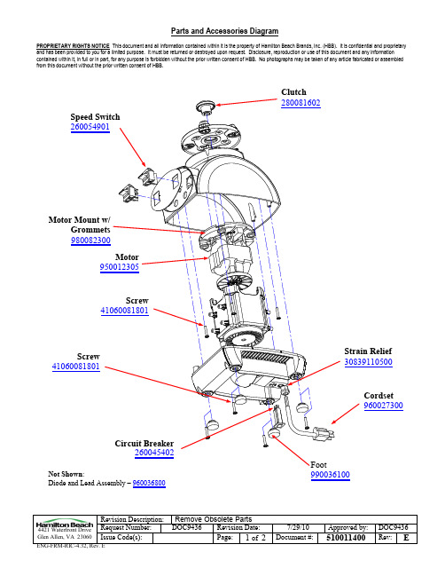
Remove Obsolete Parts DOC9436 Revision Date:
Page: 1 of 2
7/29/10 Document #:
Approved by: DOC9436
510011400 Rev: E
Parts and Accessories Diagram
Circuit Breaker 260045402
Not Shown: Diode and Lead ຫໍສະໝຸດ ssembly – 960036800
Foot 990036100
Revision Description: 4421 Waterfront Drive Request Number: Glen Allen, VA 23060 Issue Code(s):
Fill Cap 280079900
Container Cover 280121200
Container Kit 6126-91503
Revision Description: 4421 Waterfront Drive Request Number: Glen Allen, VA 23060 Issue Code(s):
Parts and Accessories Diagram
PROPRIETARY RIGHTS NOTICE This document and all information contained within it is the property of Hamilton Beach Brands, Inc. (HBB). It is confidential and proprietary and has been provided to you for a limited purpose. It must be returned or destroyed upon request. Disclosure, reproduction or use of this document and any information contained within it, in full or in part, for any purpose is forbidden without the prior written consent of HBB. No photographs may be taken of any article fabricated or assembled from this document without the prior written consent of HBB.
海尔洗衣机自检程序及童锁
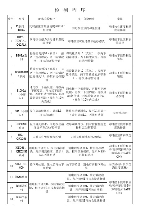
将旋钮调到10(真丝),按两下
超净漂洗,两下防皱浸泡,再按 启动/暂停键
同时按下预约和防 皱键
4
BS08B/HD S系列
将旋钮调到10(真丝),按 两下超净漂洗,两下防皱浸 泡,再调到11,再按启动/暂停
键
将旋钮调到10(真丝),按两下 超净漂洗,两下防皱浸泡,再调到
同时按下温度与自 动档按键
注:解除童锁方法同设置童锁操作方法
6
S06(小丽 人)
按住启动健通电,显示L1, 再按启动健.
按住启动健通电,显示L1后旋一 下旋钮显示L2,再按启动健
无童锁功能
7
D09\E600 系列
程序调到排水,同时按住温 程序调到排水,同时按住温度选
度选择和启动/暂停键
择和启动/暂停键
同时按住预约和温 度选择键
8
HK、 QX1266
同时按住免熨和预约键
到快洗,显示ЬE5Ь再按启动键
XQG5215 Q18系列
超净漂洗+防皱浸泡,再通 电4秒
超净漂洗+ห้องสมุดไป่ตู้皱浸泡,再通电4秒
同时按下预约和启 动按键
XQG55Q9 16 8、96系列
超净漂洗+防皱浸泡,再通 电4秒
超净漂洗+防皱浸泡,再通电4秒
同时按下预约和启 动按键(童锁有记
忆功能)
17
XQGB60Q1269系列
同时按住预洗和超净漂洗
同时按预约和预洗 键
9
HTD68、 通电程序调到0,按住超净漂 通电程序调到0,按住超净漂
QHZ68H 洗,程序调到棉麻,显示Ь 洗,程序调到棉麻,显示ЬE5Ь
- 1、下载文档前请自行甄别文档内容的完整性,平台不提供额外的编辑、内容补充、找答案等附加服务。
- 2、"仅部分预览"的文档,不可在线预览部分如存在完整性等问题,可反馈申请退款(可完整预览的文档不适用该条件!)。
- 3、如文档侵犯您的权益,请联系客服反馈,我们会尽快为您处理(人工客服工作时间:9:00-18:30)。
本标识是海尔热水器公
司“安全预警”专用标
识,内部使用了本公司
的专利技术(中国发明
专利ZL01135300.7)
,在确保您安全洗浴的
同时,时刻监测您家庭
的地线是否带电。
如本
标识点亮,则表示您家
的地线已经带电,应即刻停止使用并拔掉电源
插头,同时切记不要触及家中任何电器的外壳
,并马上联系售后部门(售后服务电话:4006
999 999)或物业公司,由专业电工进行系统检
测直至本标识熄灭。
务必使用220V/50Hz的独立电源。
为了确保安全,热水器应使用独立插座(禁止
使用多功能插座),并进行可靠接地,且插座
质量应符合国家标准,严禁在无可靠接地的情
况下使用热水器。
用测电笔测量火线、零线是
否接反。
由于此款电热水器功率较大,为保证本机的正
常工作及家庭的用电安全,在安装时必须采用
与本机插头(16A)相匹配的电源插座。
在热水够用的情况下,尽量调低设定温度,这样可以减少热损耗、高温腐蚀和结垢,延长热水器使用寿命。