PLC英文文献
英文文献-可编程逻辑控制器(PLC)英语

Programmable Logic ControllersProgrammable logic controller (plc) is a solid-state device used to control machine motion or process operation by means of a stored program. The PLC sends output control signals and receives input signals through input/output (I/O) devices. A PLC controls outputs in response to stimuli at the inputs according to the logic prescribed by the stored program. The inputs are made up of limit switches, pushbuttons, thunbwheels. Switches, pulses, analog signals, ASCLL serial data, and binary or BCD data from absolute position encoders. The outputs are voltage or current levels to drive end devices such as solenoids, motor starters, relays, lights, and so on. Other output devices include analog devices, digital BCD displays, ASCII compatible devices, servo variable-speed drives, and even computers.Programmable controllers were developed (circa in 1968) when General Motors Corp, and other automobile manufacturers were experimenting to see if there might be an alternative to scrapping all their hardwired control panels of machine tools and other production equipment during a model changeover. This annual tradition was necessary because rewiring of the panels was more expensive than buying new ones.The automotive companies approached a number of control equipment manufacturers and asked them to develop a control system that would have a longer productive life without major rewiring, but would still be understandable to and repairable by plant personnel. The new product was named a “pr ogrammable controller”.The processor part of the PLC contains a central processing unit and memory。
(完整版)PLC英文文献
ONE、PLC overviewProgrammable controller is the first in the late 1960s in the United States, then called PLC programmable logic controller (Programmable Logic Controller) is used to replace relays。
For the implementation of the logical judgment, timing, sequence number, and other control functions. The concept is presented PLC General Motors Corporation. PLC and the basic design is the computer functional improvements,flexible, generic and other advantages and relay control system simple and easy to operate, such as the advantages of cheap prices combined controller hardware is standard and overall。
According to the practical application of target software in order to control the content of the user procedures memory controller, the controller and connecting the accused convenient target。
In the mid-1970s,the PLC has been widely used as a central processing unit microprocessor, import export module and the external circuits are used, large-scale integrated circuits even when the PLC is no longer the only logical (IC) judgment functions also have data processing, PID conditioning and data communications functions. International Electro technical Commission (IEC) standards promulgated programmable controller for programmable controller draft made the following definition : programmable controller is a digital electronic computers operating system, specifically for applications in the industrial design environment。
电气工程及其自动化专业_外文文献_英文文献_外文翻译_plc方面.
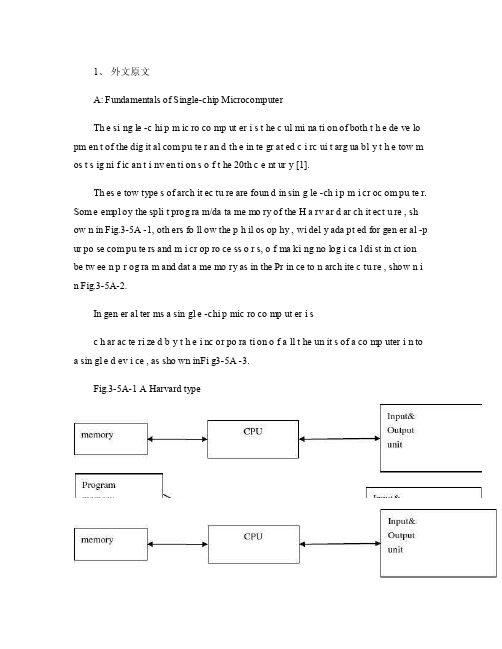
1、外文原文A: Fundamentals of Single-chip MicrocomputerTh e si ng le -c hi p m ic ro co mp ut er i s t he c ul mi na ti on of both t h e de ve lo pm en t of the dig it al com pu te r an d th e in te gr at ed c i rc ui t arg ua bl y t h e tow m os t s ig ni f ic an t i nv en ti on s o f t he 20th c e nt ur y [1].Th es e tow type s of arch it ec tu re are foun d in sin g le -ch i p m i cr oc om pu te r. Som e empl oy the spli t prog ra m/da ta me mo ry of the H a rv ar d ar ch it ect u re , sh ow n in Fig.3-5A -1, oth ers fo ll ow the p h il os op hy , wi del y ada pt ed for gen er al -p ur po se com pu te rs and m i cr op ro ce ss o r s, o f ma ki ng no log i ca l di st in ct ion be tw ee n p r og ra m and dat a me mo ry as in the Pr in ce to n arch ite c tu re , show n i n Fig.3-5A-2.In gen er al ter ms a sin gl e -chi p mic ro co mp ut er i sc h ar ac te ri zed b y t he i nc or po ra ti on of a ll t he un it s of a co mp uter i n to a sin gl e d ev i ce , as sho wn inFi g3-5A -3.Fig.3-5A-1 A Harvard typeFig.3-5A-2. A conventional Princeton computerFig3-5A-3. Principal features of a microcomputerRead only memory (ROM.R OM is usua ll y for the pe rm an ent,n o n-vo la ti le stor a ge of an app lic a ti on s pr og ra m .M an ym i cr oc om pu te rs and m are inte nd e d for high -v ol um e ap pl ic at ions a n d he nc e t h e eco n om ic al man uf act u re of th e de vic e s re qu ir es t h at t he cont en t s o f t he prog ra m me m or y be co mm it t ed perm a ne ntly d u ri ng the man ufa c tu re of ch ip s .Cl ea rl y, thi s im pl ie s a r i go ro us app ro ach to ROM cod e deve l op me nt sin ce cha ng es can not b e mad e afte r manu f a c tu re .Th is dev e lo pm en t proc ess may invo lv e e m ul at io n us in g aso ph is ti ca te d de ve lo pm en t sy ste m wit h a h a rd wa re emu la tio n cap ab il it y as w el l as the use o f po we rf ul s o ft wa re too ls.So me man uf act u re rs pro vi de add it io na l RO M opt i on s by i n cl ud in g in their ra n ge dev ic es wit h (or int en de d fo r use wit h u s er pro gr am ma ble me mo ry. Th e sim p le st of th es e is usu al ly d e vi ce whi ch can op er at e in a micro p ro ce ssor mod e by usi ng som e o f the inp ut /outp u t li ne s as an ad dr es s an d da ta b us fora c ce ss in g ex te rna l mem or y. Thi s t y pe of de vi ce can beh av ef u nc ti on al ly as th e sing le chip mi cr oc om pu te r from whi ch it is d e ri ve d al be it wit h re st ri ct ed I/O and a mod if ied ex te rn al c i rc ui t. The use of thes e d ev ic es is com mo n eve n in prod uc ti on c i rc ui ts wher e t he vo lu me does no tj us ti f y t h e d ev el o pm en t c osts o f c us to m o n -ch i p R OM [2];t he re c a n s ti ll bea s ignif i ca nt saving i n I /O and o th er c h ip s com pa re d to a conv en ti on al mi c ro pr oc es sor b a se d ci rc ui t. Mor e ex ac t re pl ace m en t fo r RO M dev i ce s ca n be o b ta in ed in th e fo rm of va ri an ts w it h 'p ig gy -b ack 'E P RO M(Er as ab le pro gr am ma bl e ROM s oc ke ts or dev ic e s with EPROM i n st ea d o f RO M 。
电气工程及其自动化专业 外文文献 英文文献 外文翻译 plc方面

1、外文原文(复印件)A: Fundamentals of Single-chip MicrocomputerTh e si ng le-ch i p mi cr oc om pu ter is t he c ul mi nat i on o f bo th t h e d ev el op me nt o f th e d ig it al com p ut er an d t he int e gr at ed ci rc ui ta r gu ab ly th e t ow m os t s i gn if ic ant i nv en ti on s o f t h e 20t h c en tu ry[1].Th es e to w typ e s of a rc hi te ctu r e ar e fo un d i n s in gl e-ch ip m i cr oc om pu te r. So m e em pl oy t he sp l it p ro gr am/d ata me mo ry o f th e H a rv ar d ar ch it ect u re, sh ow n i n -5A, ot he rs fo ll ow th e ph i lo so ph y, w i de ly a da pt ed fo r g en er al-p ur pos e c om pu te rs an d m i cr op ro ce ss or s, o f m a ki ng no lo gi c al di st in ct io n b e tw ee n p ro gr am a n d da t a m em ory a s i n th e Pr in cet o n ar ch it ec tu re,sh ow n in-5A.In g en er al te r ms a s in gl e-chi p m ic ro co mp ut er i sc h ar ac te ri zed b y the i nc or po ra tio n of al l t he uni t s o f a co mp ut er i n to a s in gl e dev i ce, as s ho wn in Fi g3-5A-3.-5A-1 A Harvard type-5A. A conventional Princeton computerFig3-5A-3. Principal features of a microcomputerRead only memory (ROM).R OM i s u su al ly f or th e p er ma ne nt, n o n-vo la ti le s tor a ge o f an a pp lic a ti on s pr og ra m .M an ym i cr oc om pu te rs an d mi cr oc on tr ol le r s a re in t en de d fo r h ig h-v ol ume a p pl ic at io ns a nd h en ce t he e co nom i ca l ma nu fa ct ure of t he d ev ic es r e qu ir es t ha t the co nt en ts o f the pr og ra m me mo ry b e co mm it te dp e rm an en tl y d ur in g th e m an uf ac tu re o f c hi ps . Cl ear l y, th is im pl ie sa ri g or ou s a pp roa c h t o R OM co de d e ve lo pm en t s in ce c ha ng es ca nn otb e m ad e af te r man u fa ct ur e .T hi s d e ve lo pm en t pr oce s s ma y in vo lv e e m ul at io n us in g a s op hi st ic at ed deve lo pm en t sy st em w i th a ha rd wa re e m ul at io n ca pa bil i ty a s we ll a s th e u se of po we rf ul so ft wa re t oo ls.So me m an uf act u re rs p ro vi de ad d it io na l RO M opt i on s byi n cl ud in g i n th ei r ra ng e de vi ce s wi th (or i nt en de d fo r us e wi th) u s er pr og ra mm ab le m em or y. Th e s im p le st of th es e i s us ua ll y d ev ice w h ic h ca n op er ate in a m ic ro pr oce s so r mo de b y usi n g so me o f th e i n pu t/ou tp ut li ne s as a n ad dr es s an d da ta b us f or acc e ss in g e xt er na l m e mo ry. T hi s t ype o f d ev ic e c an b e ha ve fu nc ti on al l y a s t he si ng le c h ip mi cr oc om pu te r fr om wh ic h i t i s de ri ve d a lb eit w it h r es tr ic ted I/O an d a mo di fie d e xt er na l ci rcu i t. T he u se o f t h es e RO Ml es sd e vi ce s is c om mo n e ve n in p ro du ct io n c ir cu it s wh er e t he v ol um e do es n o t ju st if y th e d e ve lo pm en t co sts of c us to m on-ch i p RO M[2];t he re c a n st il l b e a si g ni fi ca nt s a vi ng in I/O a nd ot he r c hi ps co mp ar ed t o a c on ve nt io nal mi cr op ro ce ss or b as ed c ir cu it. M o re e xa ctr e pl ac em en t fo r RO M d ev ic es c an b e o bt ai ne d in t he f o rm o f va ri an ts w i th 'pi gg y-ba ck'EP RO M(Er as ab le p ro gr am ma bl e ROM)s oc ke ts o rd e vi ce s w it h EP ROM i ns te ad o f R OM 。
PLC相关的外文英语文献与翻译

RelaysThe Programmable Logic ControllerEarly machines were controlled by mechanical means using cams, gears, levers and other basic mechanical devices. As the complexity grew, so did the need for a more sophisticated control system. This system contained wired relay and switch control elements. These elements were wired as required to provide the control logic necessary for the particular type of machine operation. This was acceptable for a machine that never needed to be changed or modified, but as manufacturing techniques improved and plant changeover to new products became more desirable and necessary, a more versatile means of controlling this equipment had to be developed. Hardwired relay and switch logic was cumbersome and time consuming to modify. Wiring had to be removed and replaced to provide for the new control scheme required. This modification was difficult and time consuming to design and install and any small "bug" in the design could be a major problem to correct since that also required rewiring of the system. A new means to modify control circuitry was needed. The development and testing ground for this new means was the U.S. auto industry. The time period was the late 1960's and early 1970's and the result was the programmable logic controller, or PLC. Automotive plants were confronted with a change in manufacturing techniques every time a model changed and, in some cases, for changes on the same model if improvements had to be made during the model year. The PLC provided an easy way to reprogram the wiring rather than actually rewiring the control system.The PLC that was developed during this time was not very easy to program. The language was cumbersome to write and required highly trained programmers. These early devices were merely relay replacements and could do very little else. The PLC has at first gradually, and in recent years rapidly developed into a sophisticated and highly versatile control system component. Units today are capable of performing complex math functions including numerical integration and differentiation and operate at the fast microprocessor speeds now available. Older PLCs were capable of only handling discrete inputs and outputs (that is, on-off type signals), while today's systems can accept and generate analog voltagesand currents as well as a wide range of voltage levels and pulsed signals. PLCs are also designed to be rugged. Unlike their personal computer cousin, they can typically withstand vibration, shock, elevated temperatures, and electrical noise to which manufacturing equipment is exposed.As more manufacturers become involved in PLC production and development, and PLC capabilities expand, the programming language is also expanding. This is necessary to allow the programming of these advanced capabilities. Also, manufacturers tend to develop their own versions of ladder logic language (the language used to program PLCs). This complicates learning to program PLC's in general since one language cannot be learned that is applicable to all types. However, as with other computer languages, once the basics of PLC operation and programming in ladder logic are learned, adapting to the various manufacturers’ devices is not a complicated process. Most system designers eventually settle on one particular manufacturer that produces a PLC that is personally comfortable to program and has the capabilities suited to his or her area of applications.It should be noted that in usage, a programmable logic controller is generally referred to as a “PLC” or “programmable controller”. Although the term “programmable controller” is generally accepted, it is not abbreviated “PC” because the abbreviation “PC” is usually used in reference to a personal computer. As we will see in this chapter, a PLC is by no means a personal computer.Programmable controllers (the shortened name used for programmable logic controllers) are much like personal computers in that the user can be overwhelmed by the vast array of options and configurations available. Also, like personal computers, the best teacher of which one to select is experience. As one gains experience with the various options and configurations available, it becomes less confusing to be able to select the unit that will best perform in a particular application.The typical system components for a modularized PLC are:1. Processor.The processor (sometimes call a CPU), as in the self contained units, is generally specified according to memory required for the program to beimplemented. In themodularized versions, capability can also be a factor. This includes features such as higher math functions, PID control loops and optional programming commands. The processor consists of the microprocessor, system memory, serial communication ports for printer, PLC LAN link and external programming device and, in some cases, the system power supply to power the processor and I/O modules.2. Mounting rack.This is usually a metal framework with a printed circuit board backplane which provides means for mounting the PLC input/output (I/O) modules and processor. Mounting racks are specified according to the number of modules required to implement the system. The mounting rack provides data and power connections to the processor and modules via the backplane. For CPUs that do not contain a power supply, the rack also holds the modular power supply. There are systems in which the processor is mounted separately and connected by cable to the rack. The mounting rack can be available to mount directly to a panel or can be installed in a standard 19" wide equipment cabinet. Mounting racks are cascadable so several may be interconnected to allow a system to accommodate a large number of I/O modules.3. Input and output modules.Input and output (I/O) modules are specified according to the input and output signals associated with the particular application. These modules fall into the categories of discrete, analog, high speed counter or register types.Discrete I/O modules are generally capable of handling 8 or 16 and, in some cases 32, on-off type inputs or outputs per module. Modules are specified as input or output but generally not both although some manufacturers now offer modules that can be configured with both input and output points in the same unit. The module can be specified as AC only, DC only or AC/DC along with the voltage values for which it is designed.Analog input and output modules are available and are specified according to the desired resolution and voltage or current range. As with discrete modules, these are generally input or output; however some manufacturers provide analog input and output in the same module. Analog modules are also available which can directly accept thermocouple inputsfor temperature measurement and monitoring by the PLC.Pulsed inputs to the PLC can be accepted using a high speed countermodule. This module can be capable of measuring the frequency of an inputsignal from a tachometer or other frequency generating device. These modules can also count the incoming pulses if desired. Generally, both frequency and count are available from the same module at the same time if both are required in the application.Register input and output modules transfer 8 or 16 bit words of information to and from the PLC. These words are generally numbers (BCD or Binary) which are generated from thumbwheel switches or encoder systems for input or data to be output to a display device by the PLC.Other types of modules may be available depending upon the manufacturer of the PLC and it's capabilities. These include specialized communication modules to allow for the transfer of information from one controller to another. One new development is an I/O Module which allows the serial transfer of information to remote I/O units that can be as far as 12,000 feet away.4. Power supply.The power supply specified depends upon the manufacturer's PLC being utilized in the application. As stated above, in some cases a power supply capable of delivering all required power for the system is furnished as part of the processor module. If the power supply is a separate module, it must be capable of delivering a current greater than the sum of all the currents needed by the other modules. For systems with the power supply inside the CPU module, there may be some modules in the system which require excessive power not available from the processor either because of voltage or current requirements that can only be achieved through the addition of a second power source. This is generally true if analog or external communication modules are present since these require ± DC supplies which, in the case of analog modules, must be well regulated.5. Programming unit.The programming unit allows the engineer or technician to enter and edit the program to be executed. In it's simplest form it can be a hand held device with a keypad for programentry and a display device (LED or LCD) for viewing program steps or functions, as shown. More advanced systems employ a separate personal computer which allows the programmer to write, view, edit and download the program to the PLC. This is accomplished with proprietary software available from the PLC manufacturer. This software also allows the programmer or engineer to monitor the PLC as it is running the program. With this monitoring system, such things as internal coils, registers, timers and other items not visible externally can be monitored to determine proper operation. Also, internal register data can be altered if required to fine tune program operation. This can be advantageous when debugging the program. Communication with the programmable controller with this system is via a cable connected to a special programming port on the controller. Connection to the personal computer can be through a serial port or from a dedicated card installed in the computer.A Programmable Controller is a specialized computer. Since it is a computer, it has all the basic component parts that any other computer has; a Central Processing Unit, Memory, Input Interfacing and Output Interfacing.The Central Processing Unit (CPU) is the control portion of the PLC. It interprets the program commands retrieved from memory and acts on those commands. In present day PLC's this unit is a microprocessor based system. The CPU is housed in the processor module of modularized systems.Memory in the system is generally of two types; ROM and RAM. The ROM memory contains the program information that allows the CPU to interpret and act on the Ladder Logic program stored in the RAM memory. RAM memory is generally kept alive with an on-board battery so that ladder programming is not lost when the system power is removed. This battery can be a standard dry cell or rechargeable nickel-cadmium type. Newer PLC units are now available with Electrically Erasable Programmable Read Only Memory (EEPROM) which does not require a battery. Memory is also housed in the processor module in modular systems.Input units can be any of several different types depending on input signals expected as described above. The input section can accept discrete or analog signals of various voltage and current levels. Present day controllers offer discrete signal inputs of both AC and DCvoltages from TTL to 250 VDC and from 5 to 250 V AC. Analog input units can accept input levels such as ±10 VDC, ±5 VDC and 4-20 ma. current loop values. Discrete input units present each input to the CPU as a single 1 or 0 while analog input units contain analog to digital conversion circuitry and present the input voltage to the CPU as binary number normalized to the maximum count available from the unit. The number of bits representing the input voltage or current depends upon the resolution of the unit. This number generally contains a defined number of magnitude bits and a sign bit. Register input units present the word input to the CPU as it is received (Binary or BCD).Output units operate much the same as the input units with the exception that the unit is either sinking (supplying a ground) or sourcing (providing a voltage) discrete voltages or sourcing analog voltage or current. These output signals are presented as directed by the CPU. The output circuit of discrete units can be transistors for TTL and higher DC voltage or Triacs for AC voltage outputs. For higher current applications and situations where a physical contact closure is required, mechanical relay contacts are available. These higher currents, however, are generally limited to about 2-3 amperes. The analog output units have internal circuitry which performs the digital to analog conversion and generates the variable voltage or current output.The first thing the PLC does when it begins to function is update I/O. This means that all discrete input states are recorded from the input unit and all discrete states to be output are transferred to the output unit. Register data generally has specific addresses associated with it for both input and output data referred to as input and output registers. These registers are available to the input and output modules requiring them and are updated with the discrete data. Since this is input/output updating, it is referred to as I/O Update. The updating of discrete input and output information is accomplished with the use of input and output image registers set aside in the PLC memory. Each discrete input point has associated with it one bit of an input image register. Likewise, each discrete output point has one bit of an output image register associated with it. When I/O updating occurs, each input point that is ON at that time will cause a 1 to be set at the bit address associated with that particular input. If the input is off, a 0 will be set into the bit address. Memory in today's PLC's is generallyconfigured in 16 bit words. This means that one word of memory can store the states of 16 discrete input points. Therefore, there may be a number of words of memory set aside as the input and output image registers. At I/O update, the status of the input image register is set according to the state of all discrete inputs and the status of the output image register is transferred to the output unit. This transfer of information typically only occurs at I/O update. It may be forced to occur at other times in PLC's which have an Immediate I/O Update command. This command will force the PLC to update the I/O at other times although this would be a special case.Before a study of PLC programming can begin, it is important to gain a fundamental understanding of the various types of PLCs available, the advantages and disadvantages of each, and the way in which a PLC executes a program. The open frame, shoebox, and modular PLCs are each best suited to specific types of applications based on the environmental conditions, number of inputs and outputs, ease of expansion, and method of entering and monitoring the program. Additionally, programming requires a prior knowledge of the manner in which a PLC receives input information, executes a program, and sends output information. With this information, we are now prepared to begin a study of PLC programming techniques.When writing programs for PLCs, it is beneficial to have a background in ladder diagramming for machine controls. This is basically the material that was covered in Chapter 1 of this text. The reason for this is that at a fundamental level, ladder logic programs for PLCs are very similar to electrical ladder diagrams. This is no coincidence.The engineers that developed the PLC programming language were sensitive to the fact that most engineers, technicians and electricians who work with electrical machines on a day-to-day basis will be familiar with this method of representing control logic. This would allow someone new to PLCs, but familiar with control diagrams, to be able to adapt very quickly to the programming language. It is likely that PLC programming language is one of the easiest programming languages to learn.可编程序控制器早期的机器用机械的方法采用凸轮控制、齿轮、杠杆和其他基本机械设备。
自动化专业-外文文献-英文文献-外文翻译-plc方面

1、外文原文(复印件)A: Fundamentals of Single-chip MicrocomputerTh e si ng le-ch i p mi cr oc om pu ter is t he c ul mi nat i on o f bo th t h e d ev el op me nt o f th e d ig it al com p ut er an d t he int e gr at ed ci rc ui ta r gu ab ly th e t ow m os t s i gn if ic ant i nv en ti on s o f t h e 20t h c en tu ry[1].Th es e to w t ype s o f a rc hi te ct ur e a re fo un d i n s i ng le—ch ip m i cr oc om pu te r。
S o me em pl oy th e s p li t p ro gr am/d at a me mo ry of t he H a rv ar d ar ch it ect u re, sh ow n in Fi g.3-5A—1,ot he r s fo ll ow t hep h il os op hy, wi del y a da pt ed f or ge n er al—pu rp os e c o mp ut er s an dm i cr op ro ce ss or s, of ma ki ng no lo gi c al di st in ct io n be tw ee n p ro gr am a n d da ta m em or y a s i n th e Pr in cet o n ar ch it ec tu re,sh ow n in F ig。
3-5A-2.In g en er al te r ms a s in gl e—ch i p mi cr oc om pu ter isc h ar ac te ri zed b y the i nc or po ra tio n of al l t he uni t s o f a co mp ut er i n to a s in gl e de v i ce,as s ho wn i n F ig3—5A—3。
plc英文文献

1. CONVEYOR SYSTEMS Conveyor systems are often modular in nature and can be built up from basic units (or primitives) such as linear conveyor modules, either belt or roller type, and connecting devices such as lift stations and conveyor junction modules. Complex conveyor systems can easily be configured from combinations of these standard modules. Modules are available from a range of vendors in a wide portfolio of styles and varieties [1]. Conventional conveyor systems are typically installed as simple straight assembly lines and a number of workplaces are set on each side of the conveyor for manual and/or automated operations. For simple configurations of this type, the design and implementation is a relatively trivial task. Control programs are easily designed and coded using conventional Ladder Logic Diagrams (LLDs) which can be executed by Programmable Logic Controllers (PLCs) [2]. However, today's demands for multi-product mixes and flexibility for quick system reconfiguration can require more complex conveyor systems. Traditional types of sequentially controlled conveyor installations are often found to be too rigid for such demanding operational requirements. Conveyor systems which support multiple product mixes and variable product 799
plc英文文献.pdf

Plc SynopsisCentral Processing Unit(CPU)is the brain of a PLC controller.CPU itself is usually one of the microcontrollers.Aforetime these were8-bit microcontrollers such as8051,and now these are16-and32-bit microcontrollers.Unspoken rule is that you’ll find mostly Hitachi and Fujicu microcontrollers in PLC controllers by Japanese makers,Siemens in European controllers,and Motorola microcontrollers in American ones.CPU also takes care of communication,interconnectedness among other parts of PLC controllers,program execution,memory operation,overseeing input and setting up of an output.PLC controllers have complex routines for memory checkup in order to ensure that PLC memory was not damaged(memory checkup is done for safety reasons).Generally speaking,CPU unit makes a great number of check-ups of the PLC controller itself so eventual errors would be discovered early.You can simply look at any PLC controller and see that there are several indicators in the form.of light diodes for error signalization. System memory(today mostly implemented in FLASH technology)is used by a PLC for a process control system.Aside form.this operating system it also contains a user program translated forma ladder diagram to a binary form.FLASH memory contents can be changed only in case where user program is being changed.PLC controllers were used earlier instead of PLASH memory and have had EPROM memory instead of FLASH memory which had to be erased with UV lamp and programmed on programmers.With the use of FLASH technology this process was greatly shortened.Reprogramming a program memory is done through a serial cable in a program for application development.User memory is divided into blocks having special functions.Some parts of a memory are used for storing input and output status.The real status of an input is stored either as “1”or as“0”in a specific memory bit/each input or output has one corresponding bit in memory.Other parts of memory are used to store variable contents for variables used in used program.For example,time value,or counter value would be stored in this part of the memory.PLC controller can be reprogrammed through a computer(usual way),but also through manual programmers(consoles).This practically means that each PLC controller can programmed through a computer if you have the software needed for programming. Today’s transmission computers are ideal for reprogramming a PLC controller in factory itself.This is of great importance to industry.Once the system is corrected,it is also important to read the right program into a PLC again.It is also good to check from time to time whether program in a PLC has not changed.This helps to avoid hazardous situations in factory rooms(some automakers have established communication networks which regularly check programs in PLC controllers to ensure execution only of good programs).Almost every program for programming a PLC controller possesses various useful options such as:forced switching on and off of the system input/outputs(I/O lines), program follow up in real time as well as documenting a diagram.This documenting is necessary to understand and define failures and malfunctions.Programmer can add remarks,names of input or output devices,and comments that can be useful when finding errors,or with system maintenance.Adding comments and remarks enables anytechnician(and not just a person who developed the system)to understand a ladder diagram right ments and remarks can even quote precisely part numbers if replacements would be needed.This would speed up a repair of any problems that come up due to bad parts.The old way was such that a person who developed a system had protection on the program,so nobody aside from this person could understand how it was done.Correctly documented ladder diagram allows any technician to understand thoroughly how system functions.Electrical supply is used in bringing electrical energy to central processing unit.Most PLC controllers work either at24VDC or220VAC.On some PLC controllers you’ll find electrical supply as a separate module.Those are usually bigger PLC controllers,while small and medium series already contain the supply er has to determine how much current to take from I/O module to ensure that electrical supply provides appropriate amount of current.Different types of modules use different amounts of electrical current.This electrical supply is usually not used to start external input or er has to provide separate supplies in starting PLC controller inputs because then you can ensure so called“pure”supply for the PLC controller.With pure supply we mean supply where industrial environment can not affect it damagingly.Some of the smaller PLC controllers supply their inputs with voltage from a small supply source already incorporated into a PLC二Opening and based on the industry PC controlThe PLC manufacturer already started to gaze at the formidable impact which brings based on the industry PC control technology.Some experts even believed that the new commercial activity brings new technical and the opening technology standard will bury traditional PLC.The PLC manufacturer believed that although has the massive PLC control device in the industry field installation,but they still needed to unite the labor to control the software company,with the aim of developing them based on the industry PC process control software.Indeed,several years ago have the new old PLC mix use obviously in the industry scene the situation,the industrial user can not but simultaneously study the related new old knowledge,even each other profits from the study.The majority PLC manufacturers have provided the soft logic and one kind of service platform merely for the industrial user.In the high-end application aspect,very difficult to further differentiate the PLC control system and between the industry PC control system's difference,because this both have used the similar type microprocessor and the memory chip.Makes an analogy vividly,if you forget industry PC and in the PLC these words and expressions wording meaning,then can observe in the box is some basic computer hardware technology exactly,we observe are actually these basic strokes complication and the mixture,these technologies are combined effectively in the control systemMoreover,uses the opening control the reason is the system function integration need at the same time,on the other hand is also because some industrial user makes excessive demands the result excessively to the function.If can give the high value,can obtain the more basic strokesknowledge.The PLC manufacturer concentrates the system functionalization,but the industrial user concentrates the system application.The people may see that future trend of development will be further integrates more functions to a control box.Will therefore look like the sequential control and process control such event will select the functionalization method to carry on processing,other elephant motion control and so on can also share in the same control structure system.May believe that the PLC technology will continue to the open style control system direction to shift,particularly based on industry PC control system.The latter except,in the flexible aspect has outside the entirely different superiority compared to traditional PLC,but also has other merits, like can reduce the system to put in the market the cycle,reduces the system investment expenses, enhances from the factory first floor to the enterprise office automation data message mobile efficiency and so on.Already obtained the very good solution about the industry PC control system's real-time response question,perhaps its main thing still hid behind the technology,but lacks the corresponding track record.As for PLC,ruggedness is one of its main features,this already had the quite many track records to confirm.The industrial user still very carefully treated PLC,they are doing the different technical test work to PLC.When uses one kind of new technology,the industrial user needs to consider the question is must take the big risk,simultaneously needs to consider that can bring how many opportunities and the income to its commercial activity.But the industrial user believed not completely the open style control system brings advantage.Along with the technical further development,they start to downplay these ideological concept gradually.The industrial user is being balanced uses the risk which the new technology exists and the income which brings for theirs commercial activity,in order to will provide the effective safeguard for present's decision-making.The industry PC technology has provided many functions,can strengthen PLC the function characteristic,cooperates the processor including the Inner Tibet video frequency and the high speed floating point digit.Although Microsoft Corporation has not promoted further this function characteristic plan,but new Windows CE3.0can definitely satisfy the process control well the need.Some time ago,Siemens Corporation announced a set newly based on the open style control system's software product,namely3.0edition SIMATIC WinAC(Windows automation center). WinAC is based on Windows NT,with SIMATIC S7PLC compatible suiting in industry PC control system solution.WinAC3.0provided had the high integration rate Profibus field bus local area network's connection performance,as well as long-distance programming.In addition,it also integrated for the scene control device localization has provided one kind of new DeviceNet the I/O device driver,uses in DeviceNet which connected installs I/O equipment.The Steeplechase software company has also promoted set of supports are sturdy and healthy when process control embedded Windows the NT operating system interface unit.This part further unified Steeplechase Corporation to use the SBS technology and to move was sturdy and healthy in Windows NT environment industry Compact PCI when the control software.Now,the Steeplechase Corporation's visualization logic controller already promoted to5.0editions.This controller suits in Windows NT4.0and the Windows20,002kind of operating systems,itsreal-time engine can direct and ordinary Ethernet and TCP/IP integrates in together.5.0edition's controllers have used one kind of enlargement mode OPC server driver,thus has the quicker running rate compared to the beforehand edition.Other characteristics also include the new OI network characteristic,as well as can let industrial user design the richly colorful dynamic graph picture and so on.Transysoft Corporation had promoted the new edition ISaGRAF series industrial control configuration software package recently,namely ISaGRAF PRO,it is based on the IEC61131-3 international standards,and independence in any hardware platform soft logical automation control software package.In a network process control system environment,this software package can apply in many kinds of configurations and the distributional control system's development,it has contained a set of development kit,the application procedure working platform,as well as corresponding“hypothesized machine”when movement goal.When this movement the goal can move in various hardware platform.The CTC automation Engineering firm had already issued set of new control software package MachineLogic PCLC(industry PC logic controller),this software may let industry PC act PLC the role,and was still maintaining the industry PC function characteristic.This software can complete the control task which PLC determined,and the program time is equally quick,in1ms; Can also the simultaneous working multi-duty work,but cannot simultaneously surpass16control duties.One kind has the priority and the multitasking essence mechanism is maintaining to each control duty track,guaranteed that the control duty can obtain the highest priority.This software can move the complete5kind of IEC61131-3standard program design language and the PID control procedure,supports two types the I/O control devices.One kind is looks like Profibus and DeviceNet and so on such field bus I/O equipment;Another kind is looks like ISA and PC/104 such industry PC the I/O template.Moreover,this software has also provided to control system's online edition configuration function.The procedure may95/98and under Windows NT develops in Windows and moves,but can also carry out under RTXDOS.SoftPLC Corporation also provided one kind of labor to control software product Tealware, some people were called as very vividly this kind of software product are putting on industry PC clothes'PLC.These installed on support's control system already had the small PLC form factor, but the SoftPLC Corporation's control software was already inserted to CPU.The Tealware software can satisfy each type industrial user the need,from small,single plane system to large-scale,scattered multi-control workstation application.Its characteristic including entire series I/O module,Inner Tibet Ethernet and industry serial communication connection.Recently,Tealware the software already promoted to2.3editions.And,the control software has provided in fact the infinite trapezoidal chart logical control step the foreword,simultaneously allows to have surpasses1,000,000characters the data sheets;Many OI/SCADA application connection;The Inner Tibet Java engine and the FTP server use in the long-distance maintenance and the management;Support user compile C,C,Java procedure and device driver;Suits uses in the embedded Web server;Programming online movement pattern;Firm I/O module support ability and many other standard PLC function;May move,or is A-B Corporation's PLC-which the process which inputs transforms。
- 1、下载文档前请自行甄别文档内容的完整性,平台不提供额外的编辑、内容补充、找答案等附加服务。
- 2、"仅部分预览"的文档,不可在线预览部分如存在完整性等问题,可反馈申请退款(可完整预览的文档不适用该条件!)。
- 3、如文档侵犯您的权益,请联系客服反馈,我们会尽快为您处理(人工客服工作时间:9:00-18:30)。
Keywords: Programmable logic controller; VMEbus; PLC processor module
I. Introduction Programmable logic controllers (PLCs) are being used increasingly in instrumentation and control systems in the process industry, as well as in traditional factory automation environments. They offer industrial ruggedness not found with computers, and a flexibility not found in hardwired control systems. In the early days, the PLC was an expensive electronic relay replacer [1]. Although expensive, it was very beneficial to those who could afford the cost associated with equipment purchase and installation. For this reason, early PLCs were more likely to be found in large manufacturing plants, such as General Motors, General Electric and many others. The design criteria for the first PLC were specified in 1968 by the Hydramatic division of the General Motors Corporation [2]. Since their introduction in 1968, PLCs have steadily gained in popularity in industry. From 1970 to 1974, early innovations in microprocessor technology added greater flexibility and intelligence to the PLCs [2]. Capabilities of operator interfaces (CRT terminals and hand-held programming devices), added new dimensions to the PLC applications. An 8-bit microprocessor-based
D,~,
Pro~a~m.h g
Fig. 1. General PLC system parts.
compiled BASIC. Dudeck [10] used an IBM-PC as a programming device to an industrial PLC manufactured by the Allen-Bradley Company. He illustrated a controlled diffusion pumped vacuum evacuation sequence as a ladder diagram program example for this PC-controlled PLC. Muth [11] showed how an IBM-PC can be used to emulate a PLC, and as an off-line device for control program development and debugging. He also indicated the suitability of the Turbo Pascal as a programming language for the control program as well as for simulation software. Recently, research has been directed towards translating ladder diagram language to other forms of PLC languages. Welch [12] described an algorithm for translating unrestricted relay ladder logic into Boolean form. Krogh and Falcione [13] introduced an algorithm for converting relay ladder logic into a sequential function chart (SFC). Further development in the user interface PC-station with literal languages has been carried out recently. Asmaa [14] designed a literal language compiler (called LitSTAT) for IBM-PC machines which depends on the standard literal statements of many PLC manufacturers. The compiler was written using standard C-language. The PLC is composed primarily of three parts as illustrated in Fig. 1. These parts are: the PLC processor module (PLCPM), the input/output (I/O) modules, and the programming device. The PLCPM and the I/O modules require a housing or a framework to hold and support them. This metal assembly is called the 'rack' or 'crate', which provides a means of supplying power and signals to the PLCPM and I/O modules.
Abstract This paper presents an overall view of the architecture and design of a programmable logic controller (PLC). The main objectives of the work are to design, develop, and implement a versatile PLC processor module (PLCPM) based on an industrial open bus architecture called VMEbus (IEEE 1014 Versa Module Euro-standard). The controller is inserted inside the VME crate and controls the industrial process via input and output modules that reside in the crate. The PLCPM is designed to be an intelligent module through the use of a Motorola MC68000 CPU. A method of distributed arbitration protocol, based on an algorithmic state-machine design approach, is added to the design of this module. This facility makes PLCPM suitable to work inside a VMEbus environment. The PLCPM therefore becomes adequate for use in multiprocessing PLC systems. The controller uses a host personal computer (IBM-PC) as a versatile and indispensable system component for process development, monitoring, control and supervision. Software and firmware programs are developed and written for both host-PC and PLCPM using standard C-language and 68000 assembly language, respectively. This results in a sequential control algorithm for the PLCPM and windowing user interface for the host-PC. Ladder diagram programming language is supported by this user interface. © 1998 Elsevier Science B.V.
Taha F. A1-Khudairy*, Bakir A.R. A1-Hashemy, Munqith A.J. A1-Baker