外文文献及翻译:Programmable Logic Controller PLC
毕业设计英文翻译Programmable_logic
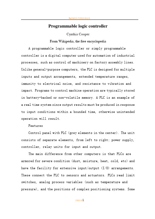
Programmable logic controllerCynthia CooperFrom Wikipedia, the free encyclopediaA programmable logic controller or simply programmable controller is a digital computer used for automation of industrial processes, such as control of machinery on factory assembly lines. Unlike general-purpose computers, the PLC is designed for multiple inputs and output arrangements, extended temperature ranges, immunity to electrical noise, and resistance to vibration and impact. Programs to control machine operation are typically stored in battery-backed or non-volatile memory. A PLC is an example of a real time system since output results must be produced in response to input conditions within a bounded time, otherwise unintended operation will result.FeaturesControl panel with PLC (grey elements in the center). The unit consists of separate elements, from left to right; power supply, controller, relay units for input and output.The main difference from other computers is that PLCs are armored for severe condition (dust, moisture, heat, cold, etc) and have the facility for extensive input/output (I/O) arrangements. These connect the PLC to sensors and actuators. PLCs read limit switches, analog process variables (such as temperature and pressure), and the positions of complex positioning systems. Someeven use machine vision. On the actuator side, PLCs operate electric motors, pneumatic or hydraulic cylinders, magnetic relays or solenoids, or analog outputs. The input/output arrangements may be built into a simple PLC, or the PLC may have external I/O modules attached to a computer network that plugs into the PLC.PLCs were invented as replacements for automated systems that would use hundreds or thousands of relays, cam timers, and drum sequencers. Often, a single PLC can be programmed to replace thousands of relays. Programmable controllers were initially adopted by the automotive manufacturing industry, where software revision replaced the re-wiring of hard-wired control panels when production models changed.Many of the earliest PLCs expressed all decision making logic in simple ladder logic which appeared similar to electrical schematic diagrams. The electricians were quite able to trace out circuit problems with schematic diagrams using ladder logic. This program notation was chosen to reduce training demands for the existing technicians. Other early PLCs used a form of instruction list programming, based on a stack-based logic solver.The functionality of the PLC has evolved over the years to include sequential relay control, motion control, process control, distributed control systems and networking. The data handling, storage, processing power and communication capabilities of some modern PLCs are approximately equivalent to desktop computers. PLC-like programming combined with remote I/O hardware, allow ageneral-purpose desktop computer to overlap some PLCs in certain applications.Under the IEC 61131-3 standard, PLCs can be programmed using standards-based programming languages. A graphical programming notation called Sequential Function Charts is available on certain programmable controllers.PLC compared with other control systemsPLCs are well-adapted to a range of automation tasks. These are typically industrial processes in manufacturing where the cost of developing and maintaining the automation system is high relative to the total cost of the automation.PLCs contain input and output devices compatible with industrial pilot devices and controls.PLC applications are typically highly customized systems so the cost of a packaged PLC is low compared to the cost of a specific custom-built controller design. On the other hand, in the case of mass-produced goods, customized control systems are economic due to the lower cost of the components, which can be optimally chosen instead of a "generic" solution。
电气系统可编程序控制器毕业论文中英文资料外文翻译文献
电气系统可编程序控制器中英文资料外文翻译文献英文原文Programmable controller designed for electro-pneumatic systems This project deals with the study of electro-pneumatic systems and theprogrammable controller that provides an effective and easy way to control thesequence of the pneumatic actuators movement and the states of pneumatic system.The project of a specific controller for pneumatic applications join the studyof automation design and the control processing of pneumatic systems with theelectronic design based on microcontrollers to implement the resources of thecontroller.1.IntroductionThe automation systems that use electro-pneumatic technology are formed mainlyby three kinds of elements: actuators or motors, sensors or buttons and controlelements like valves. Nowadays, most of the control elements used to execute thelogic of the system were substituted by the Programmable LogicController(PLC).Sensors and switches are plugged as inputs and the direct controlvalves for the actuators are plugged as outputs. An internal program executes allthe logic necessary to the sequence of the movements, simulates other componentslike counter, timer and control the status of the system.With the use of the PLC the project wins agility, because it is possible tocreate and simulate the system as many times as needed. Therefore, time can besaved, risk of mistakes reduced and complexity can be increased using the sameelements.A conventional PLC, that is possible to find on the market from many companies,offers many resources to control not only pneumatic systems, but all kinds of systemthat uses electrical components. The PLC can be very versatile and robust to beapplied in many kinds of application in the industry or even security system andautomation of buildings.Because of those characteristics, in some applications the PLC offers to much resources that are not even used to control the system, electro-pneumatic system is one of this kind of application. The use of PLC, especially for small size systems, can be very expensive for the automation project.An alternative in this case is to create a specific controller that can offer the exactly size and resources that the project needs[3,4].This can be made using microcontrollers as the base of this controller.The controller, based on microcontroller, can be very specific and adapted to only one kind of machine or it can work as a generic controller that can be programmed as a usual PLC and work with logic that can be changed. All these characteristics depend on what is needed and how much experience the designer has with developing an electronic circuit and firmware for microcontroller. But the main advantage of design the controller with the microcontroller is that the designer has the total knowledge of his controller, which makes it possible to control the size of the controller, change the complexity and the application of it. It means that the project gets more independence from other companies, but at the same time the responsibility of the control of the system stays at the designer hands2.Electro-pneumatic systemOn automation system one can find three basic components mentioned before ,plus a logic circuit that controls the system. An adequate technique is needed to project the logic circuit and integrate all the necessary components to execute the sequence of movements properly.For a simple direct sequence of movement an intuitive method can be used[1,5],but for indirect or more complex sequences the intuition can generate a very complicated circuit and signal mistakes. It is necessary to use another method that can save time of the project, make a clean circuit, can eliminate occasional signal overlapping and redundant circuits.The presented method is called step-by-step or algorithmic [1,5], it is valid for pneumatic and electro-pneumatic systems and it was used as a base in this work. The method consists of designing the systems based on standard circuits made for each change on the state of the actuators, these changes are called steps.Fig.1.Standard circuit for the pneumatic system.Fig.2.Standard circuit for the electro-pneumatic system.The first part is to design those kinds of standard circuits for each step, the next task is to link the standard circuits and the last part to connect the control element that receive signals from sensors, switches and the previous movement and give the air or electricity to the supply lines of each step. In Figs.1 and 2 the standard circuits are drawn for pneumatic and electro-pneumatic system [8].It is possible to see the relations with the previous and the next steps.3. The method applied inside the controllerThe result of the method presented before is a sequence of movements of the actuator that is well defined by steps. It means that each change on the position of the actuators is a new state of the system and the transition between statesis called step.The standard circuit described before helps the designer to define the states of the systems and to define the condition to each change between the states. In the end of the design, the system is defined by a sequence that never chances and states that have the inputs and the outputs well defined. The inputs are the condition for the transition and the outputs are the result of the transition.All the configuration of those steps stays inside of the microcontroller and is executed the same way it was designed. The sequences of strings are programmed inside the controller with 5 bytes; each string has the configuration of one step of the process. There are two bytes for the inputs, one byte for the outputs and two more for the other configurations and auxiliary functions of the step. After programming, this sequence of strings is saved inside of a non-volatile memory of the microcontroller, so they can be read and executed.The controller task is not to work in the same way as a conventional PLC, but the purpose of it is to be an example of a versatile controller that is design for an specific area. A conventional PLC process the control of the system using a cycle where it makes an image of the inputs, execute all the conditions defined by the configuration programmed inside, and then update the state of the outputs. This controller works in a different way, where it read the configuration of the step, wait the condition of inputs to be satisfied, then update the state or the outputs and after that jump to the next step and start the process again.It can generate some limitations, as the fact that this controller cannot execute, inside the program, movements that must be repeated for some time, but this problem can be solved with some external logic components. Another limitation is that the controller cannot be applied on systems that have no sequence. These limitations are a characteristic of the system that must be analyzed for each application.4. Characteristics of the controllerThe controller is based on the MICROCHIP microcontroller PIC16F877 [6,7] with 40 pins, and it has all the resources needed for this project. It ha enough pins for all the components, serial communication implemented in circuit, EEPROM memory to save all the configuration of the system and the sequence of steps. For the execution of the main program, it offers complete resources as timers and interruptions.The list of resources of the controller was created to explore all the capacity of the microcontroller to make it as complete as possible. During the step, the program chooses how to use the resources reading the configuration string of the step. This string has two bytes for digital inputs, one used as a mask and the other one used as a value expected. One byte is used to configure the outputs value. One bytes more is used for the internal timer, the analog input or time-out. The EEPROM memory inside is 256 bytes length that is enough to save the string of the steps, with this characteristic it is possible to save between 48 steps.The controller has also a display and some buttons that are used with an interactive menu to program the sequence of steps and other configurations.4.1.Interaction componentsFor the real application the controller must have some elements to interact with the final user and to offer a complete monitoring of the system resources that are available to the designer while creating the logic control of the pneumatic system:.Interactive mode of work; function available on the main program for didactic purposes, the user gives the signal to execute the step..LCD display, which shows the status of the system, values of inputs, outputs, timer and statistics of the sequence execution..Beep to give important alerts, stop, start and emergency..Leds to show power on and others to show the state of inputs and outputs.4.2. SecurityTo make the final application works property, a correct configuration to execute the steps in the right way is needed, but more then that it must offer solutions in case of bad functioning or problems in the execution of the sequence. The controller offers the possibility to configure two internal virtual circuits that work in parallel to the principal. These two circuits can be used as emergency or reset buttons and can return the system to a certain state at any time[2]. There are two inputs that work with interruption to get an immediate access to these functions. It is possible to configure the position, the buttons and the value of time-out of the system.er interfaceThe sequence of strings can be programmed using the interface elements of the controller. A computer interface can also be used to generate the user program easily. With a good documentation the final user can use the interface to configure the strings of bytes that define the steps of the sequence. But it is possible to create a program with visual resources that works as a translator to the user,it changes his work to the values that the controller understands.To implement the communication between the computer interface and the controller a simple protocol with check sum and number of bytes is the minimum requirements to guarantee the integrity of the data.4.4. FirmwareThe main loop works by reading the strings of the steps from the EEPROM memory that has all the information about the steps.In each step, the status of the system is saved on the memory and it is shown on the display too. Depending of the user configuration, it can use the interruption to work with the emergency circuit or time-out to keep the system safety.A block diagram of micro controller main program is presented.5.Example of electro-pneumatic systemThe system is not a representation of a specific machine, but it is made with some common movements and components found in a real one. The system is composed of four actuators. The actuators A,B and C are double acting and D-single acting. Actuator A advances and stays in specified position till the end of the cycle, it could work fixing an object to the next action for example(Fig.3), it is the first step. When A reaches the end position, actuator C starts his work together with B, making as many cycles as possible during the advancing of B. It depends on how fast actuator B is advancing; the speed is regulated by a flowing control valve. It was the second step. B and C are examples of actuators working together, while B pushes an object slowly, C repeats. its work for some time.Fig.3.Time diagram of A,B,C and D actuators.When B reaches the final position, C stops immediately its cycle and comes back to the initial position. The actuator D is a single acting one with spring return and works together with the back of C, it is the third step. D works making very fast forward and backward movement, just one time. Its backward movement is the fourth step. D could be a tool to make a hole on the object.When D reaches the initial position, A and B return too, it is the fifth step.Fig.4 shows the first part of the designing process where all the movements of each step should be defined[2]. (A+)means that the actuator A moves to the advanced position and (A . )to the initial position. The movements that happen at the same time are joined together in the same step. The system has five steps.Fig.4.Step sequence of A,B,C and D actuators.These two representations of the system(Figs.3 and 4) together are enough to describe correctly all the sequence. With them is possible to design the whole control circuit with the necessary logic components. But till this time, it is not a complete system, because it is missing some auxiliary elements that are not included in this draws because they work in parallel with the main sequence.These auxiliary elements give more function to the circuit and are very important to the final application; the most important of them is the parallel circuit linked with all the others steps. That circuit should be able to stop the sequence at any time and change the state of the actuators to a specific position. This kind of circuit can be used as a reset or emergency buttons.The next Figs.5 and 6 show the result of using the method without the controller. These pictures are the electric diagram of the control circuit of the example, including sensors, buttons and the coils of the electrical valves.Fig.5.Electric diagram of the example.Fig.6.Electric diagram of the example.The auxiliary elements are included, like the automatic/manual switcher that permit a continuous work and the two start buttons that make the operator of a machine use their two hands to start the process, reducing the risk of accidents.6. Changing the example to a user programIn the previous chapter, the electro-pneumatic circuits were presented, used to begin the study of the requires to control a system that work with steps andmust offer all the functional elements to be used in a real application. But, as explained above, using a PLC or this specific controller, the control becomes easier and the complexity can be increase also.It shows a resume of the elements that are necessary to control the presented example.With the time diagram, the step sequence and the elements of the system described in Figs.3 and 4 it is possible to create the configuration of the steps that can be sent to the controller.While using a conventional PLC, the user should pay attention to the logic of the circuit when drawing the electric diagram on the interface (Figs.5and 6), using the programmable controller, describe in this work, the user must know only the concept of the method and program only the configuration of each step.It means that, with a conventional PLC, the user must draw the relation between the lines and the draw makes it hard to differentiate the steps of the sequence. Normally, one needs to execute a simulation on the interface to find mistakes on the logic.The new programming allows that the configuration of the steps be separated, like described by the method. The sequence is defined by itself and the steps are described only by the inputs and outputs for each step.The structure of the configuration follows the order:1-byte: features of the step;2-byte: for the inputs;3-byte: value expected on the inputs;4-byte: value for the outputs;5-byte: value for the extra function.Fig.7.Actuators A and B, and sensors.Fig.8.Actuators C and D, and sensors.Table 5 shows how the user program is saved inside the controller, this is the program that describes the control of the example shown before.The sequence can be defined by 25 bytes. These bytes can be divided in five strings with 5 bytes each that define each step of the sequence (Figs.7 and 8).7. ConclusionThe controller developed for this work shows that it is possible to create a very useful programmable controller based on microcontroller. External memories or external timers were not used in case to explore the resources that the microcontroller offers inside. Outside the microcontroller, there are only components to implement the outputs, inputs, analog input, display for the interface and the serial communication.Using only the internal memory, it is possible to control a pneumatic system that has a sequence with 48 steps if all the resources for all steps are used, but it is possible to reach sixty steps in the case of a simpler system.The programming of the controller does not use PLC languages, but a configuration that is simple and intuitive. With electro-pneumatic system, the programming follows the same technique that was used before to design the system, but here the designer works directly with the states or steps of the system.With a very simple machine language the designer can define all the configuration of the step using four or five bytes. It depends only on his experience to use all the resources of the controller.The controller task is not to work in the same way as a commercial PLC but the purpose of it is to be an example of a versatile controller that is designed for a specific area. Because of that, it is not possible to say which one works better; the system made with microcontroller is an alternative that works in a simple way.References[1]E.Nelli Silva,Fluid-mechanics systems Manual, Escola PolitecnicaUSP,2002(in Portuguese).[2]J.Swider,Control and Automation of Technological Process and Mechatronic systems,Silesian University Publishing Company,Gli-wice,2002(redaction in Polish).[3]J.Swider, G.Wszolek, W.Carvalho. Example of the system prepared to be controlled by the controller based on microcontroller,in:12 International Scientific Conference—Achievements in Mechanical and MaterialsEngineering,Gliwice-Zakopane,Poland,2003,pp.965-970.[4]J.Swider,G.Wszolek,W.Carvalho, Controller based on microcontroller designed to execute the logic control of pneumatic systems, in:12International Scientific Conference— Achievements in Mechanical and Materials Engineering,Gliwice-Zakopane,Poland,2003,pp. 959–964.[5]J.Swider,G.Wszoek, The methodical collection of laboratory and project tasks of technological process control in Pneumatic and Electro-pneumatic Systems with Logical PLC Control, Silesian University Publishing Company,Gliwice,2003.[6]PIC 16f87xDatasheet.MICROCHIP,2001.[7]Application notes AN587 and AN546.MICROCHIP,1997.[8]Fundamental of electro-pneumatic—FESTODidactic,2000.中文翻译应用于电气系统的可编程序控制器摘要此项目主要是研究电气系统以及简单有效的控制气流发动机的程序和气流系统的状态。
可编程控制器外文翻译、中英文翻译、外文文献翻译
毕业设计中英文翻译院系专业班级姓名学号指导教师20**年 4 月Programmable Logic Controllers (PLC)1、MotivationProgrammable Logic Controllers (PLC), a computing device invented by Richard E. Morley in 1968, have been widely used in industry including manufacturing systems, transportation systems, chemical process facilities, and many others. At that time, the PLC replaced the hardwired logic with soft-wired logic or so-called relay ladder logic (RLL), a programming language visually resembling the hardwired logic, and reduced thereby the configuration time from 6 months down to 6 days [Moody and Morley, 1999].Although PC based control has started to come into place, PLC based control will remain the technique to which the majority of industrial applications will adhere due to its higher performance, lower price, and superior reliability in harsh environments. Moreover, according to a study on the PLC market of Frost and Sullivan [1995], an increase of the annual sales volume to 15 million PLCs per year with the hardware value of more than 8 billion US dollars has been predicted, though the prices of computing hardware is steadily dropping. The inventor of the PLC, Richard E Morley, fairly considers the PLC market as a 5-billion industry at the present time.Though PLCs are widely used in industrial practice, the programming of PLC based control systems is still very much relying on trial-and-error. Alike software engineering, PLC software design is facing the software dilemma or crisis in a similar way. Morley himself emphasized this aspect most forcefully by indicating [Moody and Morley, 1999, p. 110]:`If houses were built like software projects, a single woodpecker could destroy civilization.”Particularly, practical problems in PLC programming are to eliminate software bugs and to reduce the maintenance costs of old ladder logic programs. Though the hardware costs of PLCs are dropping continuously, reducing the scan time of the ladder logic is still an issue in industry so that low-cost PLCs can be used.In general, the productivity in generating PLC is far behind compared to other domains, for instance, VLSI design, where efficient computer aided design tools are in practice. Existent software engineering methodologies are not necessarily applicable to the PLC basedsoftware design because PLC-programming requires a simultaneous consideration of hardware and software. The software design becomes, thereby, more and more the major cost driver. In many industrial design projects, more than SO0/a of the manpower allocated for the control system design and installation is scheduled for testing and debugging PLC programs [Rockwell, 1999].In addition, current PLC based control systems are not properly designed to support the growing demand for flexibility and reconfigurability of manufacturing systems. A further problem, impelling the need for a systematic design methodology, is the increasing software complexity in large-scale projects.PLCs (programmable logic controllers) are the control hubs for a wide variety of automated systems and processes. They contain multiple inputs and outputs that use transistors and other circuitry to simulate switches and relays to control equipment. They are programmable via software interfaced via standard computer interfaces and proprietary languages and network options.Programmable logic controllers I/O channel specifications include total number of points, number of inputs and outputs, ability to expand, and maximum number of channels. Number of points is the sum of the inputs and the outputs. PLCs may be specified by any possible combination of these values. Expandable units may be stacked or linked together to increase total control capacity. Maximum number of channels refers to the maximum total number of input and output channels in an expanded system. PLC system specifications to consider include scan time, number of instructions, data memory, and program memory. Scan time is the time required by the PLC to check the states of its inputs and outputs. Instructions are standard operations (such as math functions) available to PLC software. Data memory is the capacity for data storage. Program memory is the capacity for control software.Available inputs for programmable logic controllers include DC, AC, analog, thermocouple, RTD, frequency or pulse, transistor, and interrupt inputs. Outputs for PLCs include DC, AC, relay, analog, frequency or pulse, transistor, and triac. Programming options for PLCs include front panel, hand held, and computer.Programmable logic controllers use a variety of software programming languages for control. These include IEC 61131-3, sequential function chart (SFC), function block diagram (FBD), ladder diagram (LD), structured text (ST), instruction list (IL), relay ladder logic (RLL), flow chart, C, and Basic. The IEC 61131-3 programming environment provides support for five languages specified by the global standard: Sequential Function Chart,Function Block Diagram, Ladder Diagram, Structured Text, and Instruction List. This allows for multi-vendor compatibility and multi-language programming. SFC is a graphical language that provides coordination of program sequences, supporting alternative sequence selections and parallel sequences. FBD uses a broad function library to build complex procedures in a graphical format. Standard math and logic functions may be coordinated with customizable communication and interface functions. LD is a graphic language for discrete control and interlocking logic. It is completely compatible with FBD for discrete function control. ST is a text language used for complex mathematical procedures and calculations less well suited to graphical languages. IL is a low-level language similar to assembly code. It is used in relatively simple logic instructions. Relay Ladder Logic (RLL), or ladder diagrams, is the primary programming language for programmable logic controllers (PLCs). Ladder logic programming is a graphical representation of the program designed to look like relay logic. Flow Chart is a graphical language that describes sequential operations in a controller sequence or application. It is used to build modular, reusable function libraries. C is a high level programming language suited to handle the most complex computation, sequential, and data logging tasks. It is typically developed and debugged on a PC. BASIC is a high level language used to handle mathematical, sequential, data capturing and interface functions.Programmable logic controllers can also be specified with a number of computer interface options, network specifications and features. PLC power options, mounting options and environmental operating conditions are all also important to consider.2、ResumeA PLC (programmable Logic Controller) is a device that was invented to replace the necessary sequential relay circuits for control.The PLC works by looking at its input and depending upon their state, turning on/off its outputs. The user enters a program, usually via software or programmer, which gives the desired results.PLC is used in many "real world" applications. If there is industry present, chance are good that there is a PLC present. If you are involved in machining, packing, material handling, automated assembly or countless other industries, you are probably already using them. If you are not, you are wasting money and time. Almost any application that needs some type of electrical control has a need for a PLC.For example, let's assume that when a switch turns on we want to turn a solenoid on for 5second and then turn it off regardless of how long the switch is on for. We can do this with a simple external timer. But what if the process included 10 switches and solenoids? We should need 10 external times. What if the process also needed to count how many times the switch individually turned on? We need a lot of external counters.As you can see the bigger the process the more of a need we have for a PLC. We can simply program the PLC to count its input and turn the solenoids on for the specified time.We will take a look at what is considered to be the "top 20" PLC instructions. It can be safely estimated that with a firm understanding of these instructions one can solve more than 80% of the applications in existence.Of course we will learn more than just these instruction to help you solve almost ALL potential PLC applications.The PLC mainly consists of a CPU, memory areas, and appropriate circuits to receive input/output data. We can actually consider the PLC to be a box full of hundreds or thousands of separate relay, counters, times and data storage locations,Do these counters,timers, etc. really exist? No,they don't "physically" exist but rather they simulated and be considered software counters, timers, etc. . These internal relays are simulated through bit locations in registers.What does each part do? Let me tell you.Input RelaysThese are connected to the outside world.They physically exsit and receive signals from switches,sensors,ect..Typically they are not relays but rather they are transistors.Internal Utility RelaysThese do not receive signals from the outside world nor do they physically exist.they are simulated relays and are what enables a PLC to eliminate external relays.There are also some special relays that are dedicated to performing only one task.Some are always on while some are always off.Some are on only once during power-on and are typically used for initializing data that was stored.CountersThese again do not physically exist. They are simulated counters and they can be programmed to count pulses.Typically these counters can count up,down or both up anddown.Since they are simulated,they are limited in their counting speed.Some manufacturers also include high-speed counters that are hardware based.We think of these as physically existing.Most times these counters can count up,down or up and down.TimersThese also do not physically exist.They come in many varieties and increments.The most common type is an on-delay type.Others include off-delays and both retentive and non-retentive types.Increments vary from 1ms through 1s.Output RelaysThere are connected to the outside world.They physically exist and send on/off signals to solenoids,lights,etc..They can be transistors,relays,or triacs depending upon the model chosen Data StorageTypically there are registers assigned to simply store data.They are usually used as temporary storage for math or data manipulation.They can also typically be used to store data when power is removed form the PLC.Upon power-up they will still have the same contents as before power was moved.Very convenient and necessary!A PLC works by continually scanning a program.We can think of this scan cycle as consisting of 3 important steps.There are typically more than 3 but we can focus on the important parts and not worry about the others,Typically the others are checking the system and updating the current internal counter and timer values,Step 1 is to check input status,First the PLC takes a look at each input to determine if it is on off.In other words,is the sensor connected to the first input on?How about the third...It records this data into its memory to be used during the next step.Step 2 is to execute program.Next the PLC executes your program one instruction at a time.Maybe your program said that if the first input was on then it should turn on the first output.Since it already knows which inputs are on/off from the previous step,it will be able to decide whether the first output should be turned on based on the state of the first input.It will store the execution results for use later during the next step.Step 3 is to update output status.Finally the PLC updates the status the outputs.It updates the outputs based on which inputs were on during the first step and the results executing your program during the second step.Based on the example in step 2 it would now turn on the firstoutput because the first input was on and your program said to turn on the first output when this condition is true.After the third step the PLC goes back to step one repeats the steps continuously.One scan time is defined as the time it takes to execute the 3 steps continuously.One scan time is defined as the time it takes to execute the 3 steps listed above.Thus a practical system is controlled to perform specified operations as desired.3、PLC StatusThe lack of keyboard, and other input-output devices is very noticeable on a PLC. On the front of the PLC there are normally limited status lights. Common lights indicate;power on - this will be on whenever the PLC has powerprogram running - this will often indicate if a program is running, or if no program is runningfault - this will indicate when the PLC has experienced a major hardware or software problemThese lights are normally used for debugging. Limited buttons will also be provided for PLC hardware. The most common will be a run/program switch that will be switched to program when maintenance is being conducted, and back to run when in production. This switch normally requires a key to keep unauthorized personnel from altering the PLC program or stopping execution. A PLC will almost never have an on-off switch or reset button on the front. This needs to be designed into the remainder of the system.The status of the PLC can be detected by ladder logic also. It is common for programs to check to see if they are being executed for the first time, as shown in Figure 1. The ’first scan’ input will be true on the very first time the ladder logic is scanned, but false on every other scan. In this case the address for ’first scan’ in a PLC-5 is ’S2:1/14’. With the logic in the example the first scan will seal on ’light’, until ’clear’ is turned on. So the light will turn on after the PLC has been turned on, but it will turn off and stay off after ’clear’ is turned on. The ’first scan’ bit is also referred to at the ’first pass’ bit.Figure 1 An program that checks for the first scan of the PLC4、Memory TypesThere are a few basic types of computer memory that are in use today.RAM (Random Access Memory) - this memory is fast, but it will lose its contents when power is lost, this is known as volatile memory. Every PLC uses this memory for the central CPU when running the PLC.ROM (Read Only Memory) - this memory is permanent and cannot be erased. It is often used for storing the operating system for the PLC.EPROM (Erasable Programmable Read Only Memory) - this is memory that can be programmed to behave like ROM, but it can be erased with ultraviolet light and reprogrammed.EEPROM (Electronically Erasable Programmable Read Only Memory) – This memory can store programs like ROM. It can be programmed and erased using a voltage, so it is becoming more popular than EPROMs.All PLCs use RAM for the CPU and ROM to store the basic operating system for the PLC. When the power is on the contents of the RAM will be kept, but the issue is what happens when power to the memory is lost. Originally PLC vendors used RAM with a battery so that the memory contents would not be lost if the power was lost. This method is still in use, but is losing favor. EPROMs have also been a popular choice for programming PLCs. The EPROM is programmed out of the PLC, and then placed in the PLC. When the PLC is turned on the ladder logic program on the EPROM is loaded into the PLC and run. This method can be very reliable, but the erasing and programming technique can be time consuming. EEPROM memories are a permanent part of the PLC, and programs can be stored in them like EPROM. Memory costs continue to drop, and newer types (such as flash memory) are becoming available, and these changes will continue to impact PLCs.5、Objective and Significance of the ThesisThe objective of this thesis is to develop a systematic software design methodology for PLC operated automation systems. The design methodology involves high-level description based on state transition models that treat automation control systems as discrete event systems, a stepwise design process, and set of design rules providing guidance and measurements to achieve a successful design. The tangible outcome of this research is to find a way to reduce the uncertainty in managing the control software development process, that is, reducing programming and debugging time and their variation, increasing flexibility of theautomation systems, and enabling software reusability through modularity. The goal is to overcome shortcomings of current programming strategies that are based on the experience of the individual software developer.A systematic approach to designing PLC software can overcome deficiencies in the traditional way of programming manufacturing control systems, and can have wide ramifications in several industrial applications. Automation control systems are modeled by formal languages or, equivalently, by state machines. Formal representations provide a high-level description of the behavior of the system to be controlled. State machines can be analytically evaluated as to whether or not they meet the desired goals. Secondly, a state machine description provides a structured representation to convey the logical requirements and constraints such as detailed safety rules. Thirdly, well-defined control systems design outcomes are conducive to automatic code generation- An ability to produce control software executable on commercial distinct logic controllers can reduce programming lead-time and labor cost. In particular, the thesis is relevant with respect to the following aspect Customer-Driven ManufacturingIn modern manufacturing, systems are characterized by product and process innovation, become customer-driven and thus have to respond quickly to changing system requirements.A major challenge is therefore to provide enabling technologies that can economically reconfigure automation control systems in response to changing needs and new opportunities. Design and operational knowledge can be reused in real-time, therefore, giving a significant competitive edge in industrial practice.Higher Degree of Design Automation and Software QualityStudies have shown that programming methodologies in automation systems have not been able to match rapid increase in use of computing resources. For instance, the programming of PLCs still relies on a conventional programming style with ladder logic diagrams. As a result, the delays and resources in programming are a major stumbling stone for the progress of manufacturing industry. Testing and debugging may consume over 50% of the manpower allocated for the PLC program design. Standards [IEC 60848, 1999; IEC-61131-3, 1993; IEC 61499, 1998; ISO 15745-1, 1999] have been formed to fix and disseminate state-of-the-art design methods, but they normally cannot participate in advancingthe knowledge of efficient program and system design.A systematic approach will increase the level of design automation through reusing existing software components, and will provide methods to make large-scale system design manageable. Likewise, it will improve software quality and reliability and will be relevant to systems high security standards, especially those having hazardous impact on the environment such as airport control, and public railroads.System ComplexityThe software industry is regarded as a performance destructor and complexity generator. Steadily shrinking hardware prices spoils the need for software performance in terms of code optimization and efficiency. The result is that massive and less efficient software code on one hand outpaces the gains in hardware performance on the other hand. Secondly, software proliferates into complexity of unmanageable dimensions; software redesign and maintenance-essential in modern automation systems-becomes nearly impossible. Particularly, PLC programs have evolved from a couple lines of code 25 years ago to thousands of lines of code with a similar number of 1/O points. Increased safety, for instance new policies on fire protection, and the flexibility of modern automation systems add complexity to the program design process. Consequently, the life-cycle cost of software is a permanently growing fraction of the total cost. 80-90% of these costs are going into software maintenance, debugging, adaptation and expansion to meet changing needs [Simmons et al., 1998].Design Theory DevelopmentToday, the primary focus of most design research is based on mechanical or electrical products. One of the by-products of this proposed research is to enhance our fundamental understanding of design theory and methodology by extending it to the field of engineering systems design. A system design theory for large-scale and complex system is not yet fully developed. Particularly, the question of how to simplify a complicated or complex design task has not been tackled in a scientific way. Furthermore, building a bridge between design theory and the latest epistemological outcomes of formal representations in computer sciences and operations research, such as discrete event system modeling, can advance future development in engineering design.Application in Logical Hardware DesignFrom a logical perspective, PLC software design is similar to the hardware design of integrated circuits. Modern VLSI designs are extremely complex with several million parts and a product development time of 3 years [Whitney, 1996]. The design process is normally separated into a component design and a system design stage. At component design stage, single functions are designed and verified. At system design stage, components are aggregated and the whole system behavior and functionality is tested through simulation. In general, a complete verification is impossible. Hence, a systematic approach as exemplified for the PLC program design may impact the logical hardware design.可编程控制器1、前言可编程序的逻辑控制器(PLC),是由Richard E.Morley 于1968年发明的,如今已经被广泛的应用于生产、运输、化学等工业中。
外文文献及翻译:Programmable Logic Controller PLC
本科毕业设计英文参考资料题目Programmable LogicController PLC院系专业姓名学号学习年限指导教师申请学位2012年05月20日英文原文:Programmable Logic Controller PLC1 PLC IntroducePLC Introduction Programmable controller is the first in the late 1960s in the United States, then called PLC programmable logic controller (Programmable Logic Controller) is used to replace relays. For the implementation of the logical judgment, timing, sequence number, and other control functions. The concept is presented PLC General Motors Coroperation.PLC and the basic design is the computer functional improvements, flexible, generic and other advantages and relay control system simple and easy to operate, such as the advantages of cheap prices combined controller hardware is standard and overall. According to the practical application of target software in order to control the content of the user procedures memory controller, the controller and connecting the accused convenient target. In the mid-1970s, the PLC has been widely used as a central processing unit microprocessor, import export module and the external circuits are used, large-scale integrated circuits even when the PLC is no longer the only logical (IC) judgment functions also have data processing, PID conditioning and data communications functions. International Electro technical Commission (IEC) standards promulgated programmable controller for programmable controller draft made the following definition: programmable controller is a digital electronic computers operating system, specifically for applications in the industrial design environment. It used programmable memory, used to implement logic in their internal storage operations, sequence control, timing, counting and arithmetic operations, such as operating instructions, and through digital and analog input and output, the control of various types of machinery or production processes. Programmable controller and related peripherals, and industrial control systems easily linked to form a whole, to expand its functional design. Programmable controller for the user, is non-contact equipment, the procedures can be changed to change production processes. The programmable controller has become a powerful tool for factory automation, widely popular replication. Programmable controller is user-oriented industries dedicated control computer, with many distinctive features.①high reliability, anti-interference capability;②programming visual, simple;③adaptability good;④functional improvements, strong functional interface.Programmable Logic Controllers (PLC), a computing device invented by Richard E. Morley, have been widely used in industry including manufacturing systems, transportation systems, chemical process facilities, and many others. At that time, the PLC replaced the hardwired logic with soft-wired logic or so-called relay ladder logic (RLL), a programming language visually resembling the hardwired logic, and reduced thereby the configuration time from 6 months down to 6 days.Although PC based control has started to come into place, PLC based control will remain the technique to which the majority of industrial applications will adhere due to its higher performance, lower price, and superior reliability in harsh environments. Moreover, according to a study on the PLC market of Frost and Sullivan, an increase of the annual sales volume to 15 million PLC per year with the hardware value of more than 8 billion US dollars has been predicted, though the prices of computing hardware is steadily dropping. The inventor of the PLC, Richard E Morley, fairly considers the PLC market as a 5-billion industry at the present time.Though PLC are widely used in industrial practice, the programming of PLC based control systems is still very much relying on trial-and-error. Alike software engineering, PLC software design is facing the software dilemma or crisis in a similar way. Morley himself emphasized this aspect most forcefully by indicating: “If houses were built like software projects, a single woodpecker could destroy civilization.”Particularly, practical problems in PLC programming are to eliminate software bugs and to reduce the maintenance costs of old ladder logic programs. Though the hardware costs of PLC are dropping continuously, reducing the scan time of the ladder logic is still an issue in industry so that low-cost PLC can be used.In general, the productivity in generating PLC is far behind compared to other domains, for instance, VLSI design, where efficient computer aided design tools are in practice. Existent software engineering methodologies are not necessarily applicable to the PLC based software design because PLC-programming requires a simultaneous consideration ofhardware and software. The software design becomes, thereby, more and more the major cost driver. In many industrial design projects, more than 50% of the manpower allocated for the control system design and installation is scheduled for testing and debugging PLC programs.In addition, current PLC based control systems are not properly designed to support the growing demand for flexibility and reconfigure ability of manufacturing systems.PLC is well-adapted to a range of automation tasks. These are typically industrial processes in manufacturing where the cost of developing and maintaining the automation system is high relative to the total cost of the automation, and where changes to the system would be expected during its operational life. PLC contains input and output devices compatible with industrial pilot devices and controls; little electrical design is required, and the design problem centers on expressing the desired sequence of operations. PLC applications are typically highly customized systems so the cost of a packaged PLC is low compared to the cost of a specific custom-built controller design. On the other hand, in the case of mass-produced goods, customized control systems are economic due to the lower cost of the components, which can be optimally chosen instead of a "generic" solution, and where the non-recurring engineering charges are spread over thousands or millions of units.For high volume or very simple fixed automation tasks, different techniques are used. For example, a consumer dishwasher would be controlled by an electromechanical cam timer costing only a few dollars in production quantities.A microcontroller-based design would be appropriate where hundreds or thousands of units will be produced and so the development cost (design of power supplies, input/output hardware and necessary testing and certification) can be spread over many sales, and where the end-user would not need to alter the control. Automotive applications are an example; millions of units are built each year, and very few end-users alter the programming of these controllers. However, some specialty vehicles such as transit busses economically use PLC instead of custom-designed controls, because the volumes are low and the development cost would be uneconomic.Very complex process control, such as used in the chemical industry, may require algorithms and performance beyond the capability of even high-performance PLC. Very high-speed or precision controls may also require customized solutions; for example,aircraft flight controls.Programmable controllers are widely used in motion control, positioning control and torque control. Some manufacturers produce motion control units to be integrated with PLC so that G-code (involving a CNC machine) can be used to instruct machine movements.PLC may include logic for single-variable feedback analog control loop, a "proportional, integral, derivative" or "PID controller". A PID loop could be used to control the temperature of a manufacturing process, for example. Historically PLC was usually configured with only a few analog control loops; where processes required hundreds or thousands of loops, a distributed control system (DCS) would instead be used. As PLC has become more powerful, the boundary between DCS and PLC applications has become less distinct.PLC has similar functionality as Remote Terminal Units. An RTU, however, usually does not support control algorithms or control loops. As hardware rapidly becomes more powerful and cheaper, RTU, PLC and DCS are increasingly beginning to overlap in responsibilities, and many vendors sell RTU with PLC-like features and vice versa. The industry has standardized on the IEC 61131-3 functional block language for creating programs to run on RTU and PLC, although nearly all vendors also offer proprietary alternatives and associated development environments.2 The structure of PLC systemStructurally divides, PLC divides into the stationary type and the combined type (module type) two kinds. Stationary PLC including the CPU board, the I/O board, demonstrated the kneading board, the memory block, the power source and so on; these elements combine not a dismountable whole. Module type PLC including the CPU module, the I/O module, the memory, the power source module, the ledger wall or the rack, these modules may defer to certain rule combination disposition.1、CPU constitutionCPU is the PLC core, plays nerve center's role, wraps PLC to have CPU at least every time, it the function which entrusts with according to the PLC system program receives and stores the user program and the data, with scanning way gathering the condition or the data which sends by the scene input device, coexisting enters the stipulation in the register,simultaneously, diagnoses the power source and in the PLC internal circuit active status and the programming process grammatical error and so on. After enters the movement, one by one reads the instruction from the user program memory, the duty which stipulated according to the instruction produces the corresponding control signal again after the analysis, directs the related control circuit.CPU mainly by the operator, controller, register and implementation of data link between them, control and state BUS, CPU unit also includes peripheral chips, bus interface and related circuitry. Memory is mainly used for storing programs and data, is an integral unit PLC.In the user view, unnecessarily detailed analysis of the CPU's internal circuitry, but the working mechanism of the various parts, or should have sufficient understanding. CPU and the control work, which will read the instructions, directives and executive orders to explain. However, the pace of work from the vibration signals. Computing devices used for digital or logic operation, under the command of the controller work.CPU speed and memory capacity are important parameters for PLC, which determines the pace of work PLC, I/O number and software capacity, etc., thereby limiting the control of the scale.2、I/O modulesPLC interface with the electrical circuit is through the input and output section (I/O) completion. I/O module integrates the PLC's I/O circuits; the input register reflecting the input signal status, output point reflects the state of the output latch. Input module will transform electrical signals into digital signals into the PLC system, the output module opposite. I/O into digital input (DI), digital outputs (DO), analog input (AI), analog output (AO) modules.3、Common I/O as followSwitching capacity: voltage level by points, with 220V AC, 110V AC, 24VDC, by Way of isolation, there is isolation and transistor isolation relays.Analog: by type of signal, a current type (4-20mA ,0-20mA), voltage (0-10V ,0-5V,-10-10V) and so on, by the precision points are 12bit, 14bit, 16bit, etc. .In addition to these general-purpose IO, there are special IO modules, such as thermal resistance, thermocouple, pulse and other modules.By I/O module specifications and to determine the number of points, I/O modules can be more or less, but the maximum number of CPU can be the basic configuration management capabilities, which by the largest floor or rack slot limit.Power ModulesPLC power supply modules for the PLC to provide the power supply integrated circuits. Meanwhile, some of them for the work input circuit to provide 24V power supply. Power input types are: AC power (220V AC or 110V AC), DC power supply (commonly used to 24VDC).Most modular PLC to use floor or rack, its role is to: electrical, the realization of the modules, so that the CPU can access all the modules on the floor, machinery and realize the connection between each module, so that each module constitutes a overall.3 Installation and debugging Of PLC control systemProgramming device: development and application programmer is the PLC to monitor the operation, inspection, maintenance indispensable device for programming, some system settings, monitor the PLC and the PLC control system working conditions, but it is not directly involved in field control run. PLC programmers are generally small hand-held programmer, the current general by the computer (running programming software) as programmer. That is, our system PC.Human Machine Interface is the simplest indicators and buttons, the current LCD screen (or touch screen) type-one operator terminal has been widely applied by the computer (running the configuration software) as a very popular man-machine interface.PLC communication network rely on advanced industrial network technology can quickly and efficiently collect, transfer of production and management of data. Therefore, the network automation system integration projects in the importance of more and more significant, even been suggested that the network is the controller's point of view argument.PLC is a service specifically for the industrial production control device, usually do not need to take measures, it can be directly used in industrial environments. However, when the production environment is too harsh, especially strong electromagnetic interference, or improper installation, can not guarantee the normal operation of PLC, and therefore should pay attention to the following questions using the.First, the working environment1. PLC required temperature in the temperature 0 ~ 55 ℃, heating installation, large components can not be placed below the space around the ventilation and cooling should be large enough, the basic unit and expansion unit interval between the need for more than 30mm; switch cabinet, the lower should be a ventilation shutters, to prevent too much direct sunlight; if the surrounding Stresses above 55 ℃, to install electric fan forced ventilation.2. PLC humidity in order to ensure the insulation performance, air relative humidity should be less than 85% (no condensation).3. PLC should be made from a strong shock vibration source, to prevent the vibration frequency of 10 ~ 55Hz frequent or continuous vibration. When the environment is inevitable when using vibration, shock absorption to take measures, such as glue, such as using shock absorption.4. Air to avoid corrosion and flammable gases, such as hydrogen chloride, hydrogen sulfide, etc.. The more the air of dust or corrosive gas environment can be installed in a closed PLC good control room or control cabinet, and install air cleaning devices.5. Power PLC power supply is 50Hz, 220 (1 ± 10%) V AC, for the power cord to the interference, PLC itself has sufficient capacity to resist. Reliability requirements for high power interference is particularly serious situation or environment, you can install a shield with variable ratio of 1:1 isolation transformer to reduce the interference between the equipment and land. Power input can also be cascaded LC filter circuitSecond, installation and wiring1. Power lines, control lines and power lines and PLC I/O lines should be split wiring, isolation transformer and PLC and I/O should be used between the cable connections.2. PLC should stay away from strong interference sources such as welding, high-power silicon rectifier devices and large power equipment, not with the high-voltage electrical switch installed in the same cabinet.3. PLC input and output separately from the best alignment, switch and analog should be laid separately. The transmission of analog signals should be shielded cable, one end or both ends of the shield should be grounding resistance should be less than the shielding layer 1 / 10.4. PLC basic unit and expansion modules and functional modules, connecting cablesshould be installed separately, to prevent interference from outside signals.5. AC output line and DC output lines do not use the same cable, the output line should be far from power lines and power lines, to avoid parallel.Third, I/O wiring terminal1. Input Connection(1) Input connection generally should not exceed 30 meters. But if the environment interfere with small, small voltage drop, the input terminalLonger be appropriate.(2) Input / output lines can not be used with a cable, input / output lines should be separated.(3) The extent possible, normally open contact form connected to the input in the establishment of the ladder and relay the same schematic2. Output connection(1) Output terminal is divided into separate output and public output. In different groups, using different types and voltage levels of output voltage. However, output in the same group can only use the same type, the same voltage level of power.(2) Since the PLC's output devices are packaged in printed circuit board and connected to the terminal board that if the load short-circuits connecting the output components, printed circuit boards will be burned, thus, applied fuse protected output devices.(3) The relay output, inductive load borne by the size, will affect the life of the relay, therefore, choose to use the relay inductive load longer working life.(4) PLC may interfere with the output load, so to take measures to control, such as the DC output of the continued flow of control protection, exchange of the output RC snubbed circuit, transistors and resistors Triad output bypass the protection.Third, the external safety circuitIn order to ensure that the entire system to work reliably in a safe condition to avoid failure due to external power supply, PLC abnormalities, misuse, and the output error caused major economic losses and human casualties, PLC necessary protection should be installed outside the circuit.(1) Emergency stop circuit. The user can load the risk of harm, in addition to be taken into account in the control program, it should design external emergency stop circuit, PLCfailure, the load can cause injury and reliable power supply cut off.(2) Protection circuit. Reversible operation such as forward and reverse operation of the control system, to set an external electrical interlock protection; reciprocating and down movement of the control system, to set the outer limit protection circuits.(3) Programmable controller self-test features such as watchdog timer check out the unusual, the output all closed. But when the PLC CPU can not control when the output fault, therefore, can damage the danger of the user load, to ensure that the equipment in a safe condition to run, need to design the external circuit to be protective.(4) Power supply overload protection. If the PLC power supply failure, interruption time of less than 10 seconds, PLC work will not be affected, if the power failure or power down more than 10 seconds exceeded allowable value, then the PLC to stop working, all the output points are also broken; when power restored If the RUN input connected, the operation automatically. Therefore, some easy to overload the input device should be set to the necessary limit protection circuits.(5) Major fault alarm and protection. Major accident-prone places, in order to ensure that the control system in a major accident is still reliable alarm and protection,should be associated with major fault signal output through the external circuit to the control system to run in the security situation.4 Digital and analog signalsDigital or discrete signals behave as binary switches, yielding simply an on or off signal (1 or 0, True or False, respectively). Push buttons, limit switches, and photoelectric sensors are examples of devices providing a discrete signal. Discrete signals are sent using voltage or current, where a specific range is designated as on and another as off. For example, a PLC might use 24 V DC I/O, with values above 22 V DC representing on, values below 2VDC representing off, and intermediate values undefined. Initially, PLC had only discrete I/O.Analog signals are like volume controls, with a range of values between zero and full-scale. These are typically interpreted as integer values (counts) by the PLC, with various ranges of accuracy depending on the device and the number of bits available to store the data. As PLC typically use 16-bit signed binary processors, the integer values are limitedbetween -32,768 and +32,767. Pressure, temperature, flow, and weight are often represented by analog signals. Analog signals can use voltage or current with a magnitude proportional to the value of the process signal. For example, an analog 0 - 10 V input or 4-20 mA would be converted into an integer value of 0 - 32767.Atonally, along with the development of the ages, the people see in produce practice, automate brought the tremendous convenience and the product quantities for people up of assurance, also eased the personnel's labor strength, reduce the establishment on the personnel. The target control of the hard realization in many complicated production lines, whole and excellent turn, the best decision etc., well-trained operation work, technical personnel or expert, governor but can judge and operate easily, can acquire the satisfied result. The research target of the artificial intelligence makes use of the calculator exactly to carry out, imitate these intelligences behavior, moderating the work through person's brain and calculators, with the mode that person's machine combine, for resolve the very complicated problem to look for the best path.中文译文:可编程控制器PLC1 PLC简介可编程控制器是60年代末在美国首先出现的,当时叫可编程逻辑控制器PLC (Programmable Logic Controller),目的是用来取代继电器。
PLC电梯控制英文文献(3600英词)
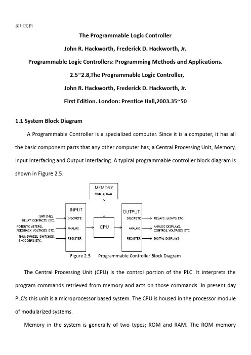
The Programmable Logic ControllerJohn R. Hackworth, Frederick D. Hackworth, Jr.Programmable Logic Controllers: Programming Methods and Applications.2.5~2.8,The Programmable Logic Controller,John R. Hackworth, Frederick D. Hackworth, Jr.First Edition. London: Prentice Hall,2003.35~501.1 System Block DiagramA Programmable Controller is a specialized computer. Since it is a computer, it has all the basic component parts that any other computer has; a Central Processing Unit, Memory, Input Interfacing and Output Interfacing. A typical programmable controller block diagram is shown in Figure 2.5.Figure 2.5 Programmable Controller Block DiagramThe Central Processing Unit (CPU) is the control portion of the PLC. It interprets the program commands retrieved from memory and acts on those commands. In present day PLC's this unit is a microprocessor based system. The CPU is housed in the processor module of modularized systems.Memory in the system is generally of two types; ROM and RAM. The ROM memorycontains the program information that allows the CPU to interpret and act on the Ladder Logic program stored in the RAM memory. RAM memory is generally kept alive with an on-board battery so that ladder programming is not lost when the system power is removed.This battery can be a standard dry cell or rechargeable nickel-cadmium type. Newer PLC units are now available with Electrically Erasable Programmable Read Only Memory (EEPROM) which does not require a battery. Memory is also housed in the processor module in modular systems.Input units can be any of several different types depending on input signals expected as described above. The input section can accept discrete or analog signals of various voltage and current levels. Present day controllers offer discrete signal inputs of both AC and DC voltages from TTL to 250 VDC and from 5 to 250 VAC. Analog input units can accept input levels such as ±10 VDC, ±5 VDC and 4-20 ma. current loop values. Discrete input units present each input to the CPU as a single 1 or 0 while analog input units contain analog to digital conversion circuitry and present the input voltage to the CPU as binary number normalized to the maximum count available from the unit. The number of bits representing the input voltage or current depends upon the resolution of the unit. This number generally contains a defined number of magnitude bits and a sign bit. Register input units present the word input to the CPU as it is received (Binaryor BCD).Output units operate much the same as the input units with the exception that the unit is either sinking (supplying a ground) or sourcing (providing a voltage) discrete voltages or sourcing analog voltage or current. These output signals are presented as directed by theCPU. The output circuit of discrete units can be transistors for TTL and higher DC voltage or Triacs for AC voltage outputs. For higher current applications and situations where a physical contact closure is required, mechanical relay contacts are available. These higher currents, however, are generally limited to about 2-3 amperes. The analog output units have internal circuitry which performs the digital to analog conversion and generates the variable voltage or current output.1.2 Update - Solve the Ladder - UpdateWhen power is applied to a programmable logic controller, the PLC’s operation consists of two steps: (1) update inputs and outputs and (2) solve the ladder. This may seem like a very simplistic approach to something that has to be more complicated but there truly are only these two steps.If these two steps are thoroughly understood, writing and modifying programs and getting the most from the device is much easier to accomplish. With this understanding, the things that can be undertaken are then up to the imagination of the programmer.You will notice that the “update - solve the ladder” sequence begins after startup. The actual startup sequence includes some operations transparent to the user or programmer that occur before actual PLC operation on the user program begins. During this startup there may be extensive diagnostic checks performed by the processor on things like memory, I/O devices, communication with other devices (if present) and program integrity. In sophisticated modular systems, the processor is able to identify the various module types, their location in the system and address. This type of system analysis and testing generally occurs during startup before actual program execution.1.3 UpdateThe first thing the PLC does when it begins to function is update I/O. This means that all discrete input states are recorded from the input unit and all discrete states to be output are transferred to the output unit. Register data generally has specific addresses associated with it for both input and output data referred to as input and output registers. These registers are available to the input and output modules requiring them and are updated with the discrete data. Since this is input/output updating, it is referred to as I/O Update. The updating of discrete input and output information is accomplished with the use of input and output image registers set aside in the PLC memory. Each discrete input point has associated with it one bit of an input image register. Likewise, each discrete output point has one bit of an output image register associated with it. When I/O updating occurs, each input point that is ON at that time will cause a 1 to be set at the bit address associated with that particular input. If the input is off, a 0 will be set into the bit address. Memory in today's PLC's is generally configured in 16 bit words. This means that one word of memory can store the states of 16 discrete input points.Therefore, there may be a number of words of memory set aside as the input and output image registers. At I/O update, the status of the input image register is set according to the state of all discrete inputs and the status of the output image register is transferred to the output unit.This transfer of information typically only occurs at I/O update. It may be forced to occur at other times in PLC's which have an Immediate I/O Update command. This command will force the PLC to update the I/O at other times although this would be a special case.One major item of concern about the first output update is the initial state of outputs.This is a concern because their may be outputs that if initially turned on could create a safety hazard, particularly in a system which is controlling heavy mechanical devices capable of causing bodily harm to operators. In some systems, all outputs may need to be initially set to their off state to insure the safety of the system. However, there may be systems that require outputs to initially be set up in a specific way, some on and some off. This could take the form of a predetermined setup or could be a requirement that the outputs remain in the state immediately before power-down. More recent systems have provisions for both setup options and even a combination of the two. This is a prime concern of the engineer and programmer and must be defined as the system is being developed to insure the safety of personnel that operate and maintain the equipment. Safety as related to system and program development will be discussed in a later chapter.1.4 Solve the LadderAfter the I/O update has been accomplished, the PLC begins executing the commands programmed into it. These commands are typically referred to as the ladder diagram. The ladder diagram is basically a representation of the program steps using relay contacts and coils. The ladder is drawn with contacts to the left side of the sheet and coils to the right.This is a holdover from the time when control systems were relay based.This type of diagram was used for the electrical schematic of those systems.A sample ladder diagram is shown in Figure 2-6.Figure 2-6 Sample Ladder DiagramThe symbols used in Figure 2.6 may be foreign at this point, so a short explana ---tion will be necessary. The symbols at the right of the ladder diagram labeled CR1, CR2, CR3 and CR4 and are circular in shape are the software coils of the relays. The symbols at the left which look like capacitors, some with diagonal lines through them , are the contacts associated with the coils. The symbols that look like capacitors with --out the diagonal lines through them are normally open contacts. These are analogous to a switch that is normally off. When the switch is turned on, the contact closes. The contact symbols at the left that look like capacitors with diagonal lines through them are normally closed contacts. A normally closed contact is equivalent to a switch that is normally turned on. It will turn off when the switch is actuated.As can be seen in Figure 2.6, contact and coil position is as described above. Also, one can see the reason for the term ladder diagram if the rungs of a stepladder are visualized. In fact, each complete line of the diagram is referred to as one rung of logic. The actual interpretation of the diagram will also be discussed later although some explanationis required here.The contact configuration on the left side of each rung can be visualized as switches and the coils on the right as lights.If the switches are turned on and off in the proper configuration, the light to the right will illuminate.The PLC executes this program from left to right and top to bottom, in that order.It first looks at the switch (contact) configuration to determine if current can be passed to the light (coil).The data for this decision comes from the output and input image registers.If current can be passed, the light (coil) will then be turned on.If not, the light (coil) will be turned off.This is recorded in the output image register Once the PLC has looked at the left side of therung it ignores the left side of the rung until the next time it solves that particular rung. Once the light (coil) has been either turned on or off it will remain in that state until the next time the PLC solves that particular rung.After solving a rung, the PLC moves on to solve the next rung in the same manner and so forth until the entire ladder has been executed and solved.One rule that is different from general electrical operation is the direction of current flow in the rung.In a ladder logic, rung current can only flow from left to right and up and down; never from right to left.As an example, in the ladder shown in Figure 2.7, coil CR1 will energize if any of thefollowing conditions exist:Figure 2.7 Illustration of allowed current flow in ladder rung1. CR7 is off, CR6 is on.2. CR7 is off, CR2 is on, CR5 is on.3. CR7 is off, CR2 is on, CR3 is on.4. CR1 is on, CR4 is on, CR3 is on.5. CR1 is on, CR4 is on, CR5 is on.You will notice that the current flow in the circuit in each of the cases listed above is from left to right and up and down. CR1 will not energize in the case listed below: CR1 is on, CR4 is on, CR2 is on, CR6 is on, CR5 is off, CR3 is off, CR7 is on.This is because current would have to flow from right to left through the CR2 contact. This is not allowed in ladder logic even though current could flow in this direction if we were to build it with real relays.Remember, we are working in the software world not the hardware world.To review, after the I/O update, the PLC moves to the first rung of ladder logic.It solves the contact configuration to determine if the coil is to be energized or de-energized.It then energizes or de-energizes the coil.After this is accomplished, it moves to the left side of the next rung and repeats the procedure.This continues until all rungs have been solved. When this procedure is complete with all rungs solved and all coils in the ladder set up according to the solution of each rung, the PLC proceeds to the next step of it's sequence, the I/O update.At I/O update, the states of all coils which are designated as outputs are transferred from the output image register to the output unit and the states of all inputs are transferred to the input image register.Note that any input changes that occur during the solution of the ladder are ignored because they are only recorded at I/O update time.The state of each coil is recorded to the output image register as each rung is solved. However, these states are not transferred to the output unit until I/O update time.Figure2.8 Scan CycleThis procedure of I/O update and solving the ladder diagram and I/O update is referred to as scanning and is represented in Figure 2.8. The period between one I/O update and the next is referred to as one Scan.The amount of time it takes the PLC to get from one I/O update to the next is referred to as Scan Time.Scan time is typically measured in milliseconds and is related to the speed of the CPU and the length of the ladder diagram that has to be solved .The slower the processor or the longer the ladder diagram, the longer the scan time of the system.The speed at which a PLC scans memory is referred to as Scan Rate.Scan rate units are usually listed in msec/K of memory being utilized for the program.As an example, if a particular PLC has a rated scan rate of 8 msec/K and the program occupies 6K of memory, it will take the PLC 48 msec to complete one scan of the program.1.5.MotivationProgrammable Logic Controllers (PLC), a computing device invented by Richard E. Morley in 1968, have been widely used in industry including manufacturing systems, transportation systems, chemical process facilities, and many others. At that time, the PLC replaced thehardwired logic with soft-wired logic or so-called relay ladder logic (RLL), aprogramming language visually resembling the hardwired logic, and reduced thereby the configuration time from 6 months down to 6 days [Moody and Morley, 1999 Although PC based control has started to come into place, PLC based control will remain the technique to which the majority of industrial applications will adhere due to its higher perfor- mance, lower price, and superior reliability in harsh environments. Moreover, according to a study on the PLC market of Frost and Sullivan [1995], an increase of the annual sales volume to 15 million PLCs per year with the hardware value of more than 8 billion US dollars has been predicted, though the prices of computing hardware is steadily dropping. The inventor of thePLC, Richard E Morley, fairly considers the PLC market as a5-billion industry at the present time.Though PLCs are widely used in industrial practice, the programming of PLC based control systems is still very much relying on trial-and-error. Alike software engineering, PLC software design is facing the software dilemma or crisis in a similar way. Morley himself emphasized this aspect most forcefully by indicating [Moody and Morley, 1999, p. 110“If houses were built like soft ware projects, a single woodpecker could destroy civilization.”Particularly, practical problems in PLC programming are to eliminate software bugs and to reduce the maintenance costs of old ladder logic programs. Though the hardware costs of PLCs are dropping continuously, reducing the scan time of the ladder logic is still an issue in industry so that low-cost PLCs can be used.In general, the productivity in generating PLC is far behind compared to other domains, for instance, VLSI design, where efficient computer aided design tools are in practice. Existent software engineering methodologies are not necessarily applicable to the PLC based software design because PLC-programming requires a simultaneous consideration ofhardware and software. The software design becomes, thereby, more and more the major cost driver. In many industrial design projects, more than SO0/a of the manpower allocated for the control system design and installation is scheduled for testing and debugging PLC programs [Rockwell, 1999].In addition, current PLC based control systems are not properly designed to support the growing demand for flexibility and reconfigurability of manufacturing systems. A further problem, impelling the need for a systematic design methodology, is the increasing software complexity in large-scale projects1.6.Objective and Significance of the ThesisThe objective of this thesis is to develop a systematic software design methodology for PLC operated automation systems. The design methodology involves high-level description based on state transition models that treat automation control systems as discrete event systems, a stepwise design process, and set of design rules providing guidance and measurements to achieve a successful design. The tangible outcome of this research is to find a way to reduce the uncertainty in managing the control software development process, hat is, reducing programming and debugging time and their variation, increasing flexibility of the automation systems, and enabling software reusability through modularity. The goal is to overcome shortcomings of current programming strategies that are based on the experience of the individual software developerDesign Theory DevelopmentToday, the primary focus of most design research is based on mechanical or electrical products. One of the by-products of this proposed research is to enhance our fundamental understanding of design theory and methodology by extending it to the field of engineeringsystems design. A system design theory for large-scale and complex system is not yet fully developed. Particularly, the question of how to simplify a complicated or complex design task has not been tackled in a scientific way. Furthermore, building a bridge between design theory and the latest epistemological outcomes of formal representations in computer sciences and operations research, such as discrete event system modeling, can advance future development in engineering designApplication in Logical Hardware DesignFrom a logical perspective, PLC software design is similar to the hardware design of integrated circuits. Modern VLSI designs are extremely complex with several million parts and a product development time of 3 years [Whitney, 1996]. The design process is normally separated into a component design and a system design stage. At component design stage, single functions are designed and verified. At system design stage, components are aggregated and the whole system behavior and functionality is tested through simulation. In general, a complete verification is impossible. Hence, a systematic approach as exemplified for the PLC program design may impact the logical hardware designPLCPLC (programmable logical controller )face ever more complex challenge these days. Where once they quietly relays and gave an occasional report to a corporate mainframe, they are now grounded into cells, give new jobs and new languages, and are forced to compete against a growing array of control products. For this year ’s annual PLC technology update, we queried PLC makers on these topics and moreProgramming languagesHigher level PLC programming languages have been around for some time, but latelytheir popularity has been mushrooming. As Raymond Lavelle, vice president and general manager, Siemens Energy and Automation. Inc, Programmable Controls Division, points out : ” As programmable controls are being used for more and more sophisticated operations, languages other than ladder logic become more practical, efficient, and powerful. For example, it's very difficult to write a trigonometric function using ladder logic. ” Languages gaining acceptance include Boolean, control system flowcharting, and such function chart languages as Graphtec and its variations. And these’s increasing interest in languages like C and BASIC.PLCs in process control Thus far, PLCs have not been used extensively for continuous process control. Will this continue? ”The feeling that I ’ve gotten, ” says Ken Jeannette, manager, product planning, Series One and Series Six products, at GE Frame North America, "is that PLCs will be used in the process industry but not necessarily for process control.”Several vendors-obviously betting that the opposite will happen-have introduced PLCs optimized for process applications. Rich Ryan ,manager, commercial marketing, Allen-Bradley Programmable Controls Div, cites PLCs ’ increasing use in such industries as food, chemicals,and petroleum. Ryan feel there are two types of applications in which they’re appropriate.”One,"he says, "is where the size of the process control system that's being automated doesn’t justify DCS[distributed control systems].With the starting price tags of those products being relatively high, a programmable controller makes sense for small, low loop count applications. The seconds where you have to integrate the loop closely with the sequential logic. Batch controller sere prime examples, where the sequence and maintaining the process variable are intertwined so closely that the benefits of having a programmable controller to do the sequential logic outweighs someof the disadvantages of not having a distributed control system.”Bill Barkovtz, president of Triconex, predicts that "all future controllers that come out in the process control system business will embrace a lot more PLC technology and a lot more PLC functionality than they ever did before.”中文翻译可编程逻辑控制器约翰R Hackworth,弗雷德里克 D Hackworth.可编程逻辑控制器:编程方法及应用.2.5~2.8,可编程逻辑控制器,约翰R Hackworth,弗雷德里克 D Hackworth第一版. 伦敦:普伦蒂斯霍尔出版社,2003,35~50一系统框图可编程控制器是一种专用的计算机。
自动化专业-外文文献-英文文献-外文翻译-plc方面

1、外文原文(复印件)A: Fundamentals of Single-chip MicrocomputerTh e si ng le-ch i p mi cr oc om pu ter is t he c ul mi nat i on o f bo th t h e d ev el op me nt o f th e d ig it al com p ut er an d t he int e gr at ed ci rc ui ta r gu ab ly th e t ow m os t s i gn if ic ant i nv en ti on s o f t h e 20t h c en tu ry[1].Th es e to w t ype s o f a rc hi te ct ur e a re fo un d i n s i ng le—ch ip m i cr oc om pu te r。
S o me em pl oy th e s p li t p ro gr am/d at a me mo ry of t he H a rv ar d ar ch it ect u re, sh ow n in Fi g.3-5A—1,ot he r s fo ll ow t hep h il os op hy, wi del y a da pt ed f or ge n er al—pu rp os e c o mp ut er s an dm i cr op ro ce ss or s, of ma ki ng no lo gi c al di st in ct io n be tw ee n p ro gr am a n d da ta m em or y a s i n th e Pr in cet o n ar ch it ec tu re,sh ow n in F ig。
3-5A-2.In g en er al te r ms a s in gl e—ch i p mi cr oc om pu ter isc h ar ac te ri zed b y the i nc or po ra tio n of al l t he uni t s o f a co mp ut er i n to a s in gl e de v i ce,as s ho wn i n F ig3—5A—3。
外文翻译--可编程逻辑控制器介绍
外文翻译--可编程逻辑控制器介绍What is a PLC?A PLC (i.e. Programmable Logic Controller) is a device that was invented to replace the necessary sequential relay circuits for machine control. The PLC works by looking at its inputs and depending upon their state, turning on/off its outputs. The user enters a program, usually via software, that gives the desired results. PLCs are used in many "real world" applications. If there is industry present, chances are good that there is a plc present. If you are involved in machining, packaging, material handling, automated assembly or countless other industries you are probably already using them. If you are not, you are wasting money and time. Almost any application that needs some type of electrical control has a need for a plc. For example, let's assume that when a switch turns on we want to turn a solenoid on for 5 seconds and then turn it off regardless of how long the switch is on for. We can do this with a simple external timer. But what if the process included 10 switches and solenoids? We would need 10 external timers. What if the process also needed to count how many times the switches individually turned on? We need a lot of external counters.As you can see the bigger the process the more of a need we have for a PLC. We can simply program the PLC to count its inputs and turn the solenoids on for the specified time.PLC HistoryIn the late 1960's PLCs were first introduced. The primary reasonfor designing such a device was eliminating the large cost involved in replacing the complicated relay based machine control systems. Bedford Associates (Bedford, MA) proposed something called a Modular Digital Controller (MODICON) to a major US car manufacturer. Other companies at the time proposed computer based schemes, one of which was based upon the PDP-8. The MODICON 084 brought the world's first PLC into commercial production.When production requirements changed so did the control system. This becomes very expensive when the change is frequent. Since relays are mechanical devices they also have a limited lifetime which requiredstrict adhesion to maintenance schedules.Troubleshooting was also quite tedious when so many relays are involved. Now picture a machine control panel that included many, possibly hundreds or thousands, of individual relays. The size could be mind boggling. How about the complicated initial wiring of so many individual devices! These relays would be individually wired together in a manner that would yield the desired outcome. Were there problems? You bet!These "new controllers" also had to be easily programmed by maintenance and plant engineers. The lifetime had to be long and programming changes easily performed. They also had to survive the harsh industrial environment. That's a lot to ask! The answers were to use aprogramming technique most people were already familiar with and replace mechanical parts with solid-state ones.In the mid70's the dominant PLC technologies were sequencer state-machines and the bit-slice based CPU. The AMD 2901 and 2903 were quite popular in Modicon and A-B PLCs. Conventional microprocessors lacked the power to quickly solve PLC logic in all but the smallest PLCs. As conventional microprocessors evolved, larger and larger PLCs were being based upon them. However, even today some are still based upon the 2903.(ref A-B's PLC-3) Modicon has yet to build a faster PLC than their 984A/B/X which was based upon the 2901.Communications abilities began to appear in approximately 1973. The first such system was Modicon's Modbus. The PLC could now talk to other PLCs and they could be far away from the actual machine they were controlling. They could also now be used to send and receive varying voltages to allow them to enter the analog world. Unfortunately, the lack of standardization coupled with continually changing technology has made PLC communications a nightmare of incompatible protocols and physical networks. Still, it was a great decade for the PLC!The 80's saw an attempt to standardize communications with General Motor's manufacturing automation protocol(MAP). It was also a time for reducing the size of the PLC and making them software programmable through symbolic programming on personal computers instead of dedicated programming terminals or handheld programmers. Today the world's smallest PLC is about the size of a single control relay!The 90's have seen a gradual reduction in the introduction of new protocols, and the modernization of the physical layers of some of the more popular protocols that survived the 1980's. The latest standard has tried to merge plc programming languagesunder one international standard. We now have PLCs that are programmable in function block diagrams, instruction lists, C and structured text all at the same time! PC's are also being used toreplace PLCs in some applications. The original company who commissioned the MODICON 084 has actually switched to a PC based control system.What will the 00's bring? Only time will tell.PLC OperationA PLC works by continually scanning a program. We can think of this scan cycle as consisting of 3 important steps. There are typically more than 3 but we can focus on the important parts and not worry about the others. Typically the others are checking the system and updating the current internal counter and timer values. Step 1-CHECK INPUT STATUS-First the PLC takes a look at each input to determine if it is on or off. In other words, is the sensor connected to the first input on? How about the second input? How about the third... It records this data into its memory to be used during the next step.Step 2-EXECUTE PROGRAM-Next the PLC executes your program oneinstruction at a time. Maybe your program said that if the firstinput was on then it should turn on the first output. Since it already knows which inputs are on/off from the previous step it will be able todecide whether the first output should be turned on based on the state of the first input. It will store the execution results for use later during the next step.Step 3-UPDATE OUTPUT STATUS-Finally the PLC updates the status ofthe outputs. It updates the outputs based on which inputs were on during the first step and the results of executing your program during the second step. Based on the example in step 2 it would now turn on thefirst output because the first input was on and your program said to turn on the first output when this condition is true. After the third step the PLC goes back to step one and repeats the steps continuously. One scan time is defined as the time it takes to execute the 3 steps listed above.PLC advantagesNow that we understand how the PLC processes inputs, outputs, andthe actual program we are almost ready to start writing a program. But first lets see how a relay actually works. After all, the main purpose of a plc is to replace "real-world" relays. We can think of a relay as an electromagnetic switch. Apply a voltage to the coil and a magnetic field is generated. This magnetic field sucks the contacts of the relay in, causing them to make a connection. These contacts can be considered to be a switch. They allow current to flow between 2 points thereby closing the circuit. Let's consider the following example. Here we simply turn on a bell (Lunch time!) whenever a switch is closed. We have 3 real-world parts. A switch, a relay and a bell. Whenever the switchcloses we apply a current to a bell causing it to sound. Notice in the picture that we have 2 separate circuits. The bottom(blue) indicates the DC part. The top(red) indicates the AC part.Here we are using a dc relay to control an AC circuit. That's thefun of relays! When the switch is open no current can flow through the coil of the relay. As soon as the switch is closed, however, currentruns through the coil causing a magnetic field to build up. This magnetic field causes the contacts of the relay to close. Now AC current flows through the bell and we hear it. Lunch time!Next, lets use a plc in place of the relay. (Note that this mightnot be very cost effective for this application but it does demonstrate the basics we need.) The first thing that's necessary is to createwhat's called a ladder diagram. After seeing a few of these it will become obvious why its called a ladder diagram. We have to create one of these because, unfortunately, a plc doesn't understand a schematic diagram. It only recognizes code. Fortunately most PLCs have software which convert ladder diagrams into code. This shields us from actually learning the plc's code. First step- We have to translate all of the items we're using into symbols the plc understands. The plc doesn't understand terms like switch, relay, bell, etc. It prefers input, output, coil, contact, etc. It doesn't care what the actual input or output device actually is. It only cares that its an input or an output.First we replace the battery with a symbol. This symbol is common to all ladder diagrams. We draw what are called bus bars. These simply looklike two vertical bars. One on each side of the diagram. Think of theleft one as being + voltage and the right one as being ground. Further think of the current (logic) flow as being from left toright.Next we give the inputs a symbol. In this basic example we have one real world input. (i.e. the switch) We give the input that the switchwill be connected to, to the symbol shown below. This symbol can also be used as the contact of a relay.A contact symbolNext we give the outputs a symbol. In this example we use one output (i.e. the bell). We give the output that the bell will be physically connected to the symbol shown below. This symbol is used as the coil of a relay.A coil symbolThe AC supply is an external supply so we don't put it in our ladder. The plc only cares about which output it turns on and not what's physically connected to it. Second step- We must tell the plc where everything is located. In other words we have to give all the devices an address. Where is the switch going to be physically connected to the plc? How about the bell? We start with a blank road map in the PLCs town and give each item an address. Could you find your friends if you didn't know their address? You know they live in the same town but which house?The plc town has a lot of houses (inputs and outputs) but we have to figure out who lives where (what device is connected where). We'll get further into the addressing scheme later. The plc manufacturers each do it a different way! For now let's say that our input will be called "0000". The output will be called "500".Final step- We have to convert the schematic into a logical sequence of events. This is much easier than it sounds. The program we're going to write tells the plc what to do when certain events take place. In our example we have to tell the plc what to do when the operator turns on the switch. Obviously we want the bell to sound but the plc doesn't know that. It's a pretty stupid device, isn't it!The picture above is the final converted diagram. Notice that we eliminated the real world relay from needing a symbol. It's actually "inferred" from the diagram. Huh? Don't worry, you'll see what we mean as we do more examples.1.PLC是什么PLC ,即可编程逻辑控制器,是发明用于取代必要的顺序继电器的机器控制电路一种装臵。
可编程控制器本科毕业论文中英文翻译材料关于PLC外文翻译
可编程控制器本科毕业论文中英文翻译材料关于PLC外文翻译中文翻译可编程控制器技术可编程序控制器(Programmable Logic Controller,习惯上简称为PLC)是以微处理器为核心的通用工业自动化装置。
是20世纪60年代末在继电器控制系统的基础上开发出来的,它将传统的继电器控制技术与计算机技术和通信技术融为一体,具有结构简单、性能优越、可靠性高、灵活通用、易于编程、使用方便等优点。
具体来说,PLC的特点表现为以下几个方面:?硬件的可靠性高。
PLC专业在工业环境的恶劣条件下应用而设计。
一个设计良好的PLC能置于有很强电噪声、电磁干扰、机械振动、极端温度和湿度很大的环境中。
在硬件设计方面,首先是选用优质器件,再就是采用合理的系统结构,加固、简化安装,使它易于抗振冲击,对印刷电路板的设计、加工和焊接都采取了极为严格的工艺措施,而在电路、结构及工艺上采取了一些独特的方式。
由于PLC 本身具有很高的可靠性,所以在发生故障的部位大多集中在输入/输出的部位以及如传感器件、限位开关、光电开关、电磁阀、电机等外围装置上。
?编程简单,使用方便。
用微机实现自动控制,常使用汇编语言编程,难于掌握,要求使用者具有一定水平的计算机硬件和软件知识。
PLC采用面向控制过程、面向问题的编程方式,与目前微机控制常用的汇编语言相比,虽然在PLC内部增加了解释程序,增加了程序的执行时间,但对大多数的机电控制设备来说,这种损耗是微不足道的。
?接线简单,通用性好。
在电信号匹配的情况下,PLC的接线只需将输入信号的设备(按钮、开关等)与PLC输入端子连接,将接受输出信号执行控制任务的执行元件(接触器、电磁阀)与PLC输出端子连接。
接线简单、工作量少,省去了传统的继电器控制系统的接线和拆线的麻烦。
PLC的编程逻辑提供了能随要求而改变的逻辑关系,这样生产线的自动化过程就能随意改变。
这种性能使PLC具有很高的经济效益。
用于连接现场设备的硬件接口实际上已经设计成为PLC的组成部分,模块化的自诊断接口电路能指出故障,并易于排除故障与替换故障部件,这样的软硬件设计就使现场电气人员与技术人员易于使用。
- 1、下载文档前请自行甄别文档内容的完整性,平台不提供额外的编辑、内容补充、找答案等附加服务。
- 2、"仅部分预览"的文档,不可在线预览部分如存在完整性等问题,可反馈申请退款(可完整预览的文档不适用该条件!)。
- 3、如文档侵犯您的权益,请联系客服反馈,我们会尽快为您处理(人工客服工作时间:9:00-18:30)。
本科毕业设计英文参考资料题目Programmable LogicController PLC院系专业姓名学号学习年限指导教师申请学位英文原文:Programmable Logic Controller PLC1 PLC IntroducePLC Introduction Programmable controller is the first in the late 1960s in the United States, then called PLC programmable logic controller (Programmable Logic Controller) is used to replace relays. For the implementation of the logical judgment, timing, sequence number, and other control functions. The concept is presented PLC General Motors Coroperation.PLC and the basic design is the computer functional improvements, flexible, generic and other advantages and relay control system simple and easy to operate, such as the advantages of cheap prices combined controller hardware is standard and overall. According to the practical application of target software in order to control the content of the user procedures memory controller, the controller and connecting the accused convenient target. In the mid-1970s, the PLC has been widely used as a central processing unit microprocessor, import export module and the external circuits are used, large-scale integrated circuits even when the PLC is no longer the only logical (IC) judgment functions also have data processing, PID conditioning and data communications functions. International Electro technical Commission (IEC) standards promulgated programmable controller for programmable controller draft made the following definition: programmable controller is a digital electronic computers operating system, specifically for applications in the industrial design environment. It used programmable memory, used to implement logic in their internal storage operations, sequence control, timing, counting and arithmetic operations, such as operating instructions, and through digital and analog input and output, the control of various types of machinery or production processes. Programmable controller and related peripherals, and industrial control systems easily linked to form a whole, to expand its functional design. Programmable controller for the user, is non-contact equipment, the procedures can be changed to change production processes. The programmable controller has become a powerful tool for factory automation, widely popularreplication. Programmable controller is user-oriented industries dedicated control computer, with many distinctive features.①high reliability, anti-interference capability;②programming visual, simple;③adaptability good;④functional improvements, strong functional interface.Programmable Logic Controllers (PLC), a computing device invented by Richard E. Morley, have been widely used in industry including manufacturing systems, transportation systems, chemical process facilities, and many others. At that time, the PLC replaced the hardwired logic with soft-wired logic or so-called relay ladder logic (RLL), a programming language visually resembling the hardwired logic, and reduced thereby the configuration time from 6 months down to 6 days.Although PC based control has started to come into place, PLC based control will remain the technique to which the majority of industrial applications will adhere due to its higher performance, lower price, and superior reliability in harsh environments. Moreover, according to a study on the PLC market of Frost and Sullivan, an increase of the annual sales volume to 15 million PLC per year with the hardware value of more than 8 billion US dollars has been predicted, though the prices of computing hardware is steadily dropping. The inventor of the PLC, Richard E Morley, fairly considers the PLC market as a 5-billion industry at the present time.Though PLC are widely used in industrial practice, the programming of PLC based control systems is still very much relying on trial-and-error. Alike software engineering, PLC software design is facing the software dilemma or crisis in a similar way. Morley himself emphasized this aspect most forcefully by indicating: “If houses were built like software projects, a single woodpecker could destroy civilization.”Particularly, practical problems in PLC programming are to eliminate software bugs and to reduce the maintenance costs of old ladder logic programs. Though the hardware costs of PLC are dropping continuously, reducing the scan time of the ladder logic is still an issue in industry so that low-cost PLC can be used.In general, the productivity in generating PLC is far behind compared to other domains, for instance, VLSI design, where efficient computer aided design tools are in practice.Existent software engineering methodologies are not necessarily applicable to the PLC based software design because PLC-programming requires a simultaneous consideration of hardware and software. The software design becomes, thereby, more and more the major cost driver. In many industrial design projects, more than 50% of the manpower allocated for the control system design and installation is scheduled for testing and debugging PLC programs.In addition, current PLC based control systems are not properly designed to support the growing demand for flexibility and reconfigure ability of manufacturing systems.PLC is well-adapted to a range of automation tasks. These are typically industrial processes in manufacturing where the cost of developing and maintaining the automation system is high relative to the total cost of the automation, and where changes to the system would be expected during its operational life. PLC contains input and output devices compatible with industrial pilot devices and controls; little electrical design is required, and the design problem centers on expressing the desired sequence of operations. PLC applications are typically highly customized systems so the cost of a packaged PLC is low compared to the cost of a specific custom-built controller design. On the other hand, in the case of mass-produced goods, customized control systems are economic due to the lower cost of the components, which can be optimally chosen instead of a "generic" solution, and where the non-recurring engineering charges are spread over thousands or millions of units.For high volume or very simple fixed automation tasks, different techniques are used. For example, a consumer dishwasher would be controlled by an electromechanical cam timer costing only a few dollars in production quantities.A microcontroller-based design would be appropriate where hundreds or thousands of units will be produced and so the development cost (design of power supplies, input/output hardware and necessary testing and certification) can be spread over many sales, and where the end-user would not need to alter the control. Automotive applications are an example; millions of units are built each year, and very few end-users alter the programming of these controllers. However, some specialty vehicles such as transit busses economically use PLC instead of custom-designed controls, because the volumes are low and the development cost would be uneconomic.Very complex process control, such as used in the chemical industry, may requirealgorithms and performance beyond the capability of even high-performance PLC. Very high-speed or precision controls may also require customized solutions; for example, aircraft flight controls.Programmable controllers are widely used in motion control, positioning control and torque control. Some manufacturers produce motion control units to be integrated with PLC so that G-code (involving a CNC machine) can be used to instruct machine movements.PLC may include logic for single-variable feedback analog control loop, a "proportional, integral, derivative" or "PID controller". A PID loop could be used to control the temperature of a manufacturing process, for example. Historically PLC was usually configured with only a few analog control loops; where processes required hundreds or thousands of loops, a distributed control system (DCS) would instead be used. As PLC has become more powerful, the boundary between DCS and PLC applications has become less distinct.PLC has similar functionality as Remote Terminal Units. An RTU, however, usually does not support control algorithms or control loops. As hardware rapidly becomes more powerful and cheaper, RTU, PLC and DCS are increasingly beginning to overlap in responsibilities, and many vendors sell RTU with PLC-like features and vice versa. The industry has standardized on the IEC 61131-3 functional block language for creating programs to run on RTU and PLC, although nearly all vendors also offer proprietary alternatives and associated development environments.2 The structure of PLC systemStructurally divides, PLC divides into the stationary type and the combined type (module type) two kinds. Stationary PLC including the CPU board, the I/O board, demonstrated the kneading board, the memory block, the power source and so on; these elements combine not a dismountable whole. Module type PLC including the CPU module, the I/O module, the memory, the power source module, the ledger wall or the rack, these modules may defer to certain rule combination disposition.1、CPU constitutionCPU is the PLC core, plays nerve center's role, wraps PLC to have CPU at least every time, it the function which entrusts with according to the PLC system program receives andstores the user program and the data, with scanning way gathering the condition or the data which sends by the scene input device, coexisting enters the stipulation in the register, simultaneously, diagnoses the power source and in the PLC internal circuit active status and the programming process grammatical error and so on. After enters the movement, one by one reads the instruction from the user program memory, the duty which stipulated according to the instruction produces the corresponding control signal again after the analysis, directs the related control circuit.CPU mainly by the operator, controller, register and implementation of data link between them, control and state BUS, CPU unit also includes peripheral chips, bus interface and related circuitry. Memory is mainly used for storing programs and data, is an integral unit PLC.In the user view, unnecessarily detailed analysis of the CPU's internal circuitry, but the working mechanism of the various parts, or should have sufficient understanding. CPU and the control work, which will read the instructions, directives and executive orders to explain. However, the pace of work from the vibration signals. Computing devices used for digital or logic operation, under the command of the controller work.CPU speed and memory capacity are important parameters for PLC, which determines the pace of work PLC, I/O number and software capacity, etc., thereby limiting the control of the scale.2、I/O modulesPLC interface with the electrical circuit is through the input and output section (I/O) completion. I/O module integrates the PLC's I/O circuits; the input register reflecting the input signal status, output point reflects the state of the output latch. Input module will transform electrical signals into digital signals into the PLC system, the output module opposite. I/O into digital input (DI), digital outputs (DO), analog input (AI), analog output (AO) modules.3、Common I/O as followSwitching capacity: voltage level by points, with 220V AC, 110V AC, 24VDC, by Way of isolation, there is isolation and transistor isolation relays.Analog: by type of signal, a current type (4-20mA ,0-20mA), voltage (0-10V ,0-5V,-10-10V) and so on, by the precision points are 12bit, 14bit, 16bit, etc. .In addition to these general-purpose IO, there are special IO modules, such as thermal resistance, thermocouple, pulse and other modules.By I/O module specifications and to determine the number of points, I/O modules can be more or less, but the maximum number of CPU can be the basic configuration management capabilities, which by the largest floor or rack slot limit.Power ModulesPLC power supply modules for the PLC to provide the power supply integrated circuits. Meanwhile, some of them for the work input circuit to provide 24V power supply. Power input types are: AC power (220V AC or 110V AC), DC power supply (commonly used to 24VDC).Most modular PLC to use floor or rack, its role is to: electrical, the realization of the modules, so that the CPU can access all the modules on the floor, machinery and realize the connection between each module, so that each module constitutes a overall.3 Installation and debugging Of PLC control systemProgramming device: development and application programmer is the PLC to monitor the operation, inspection, maintenance indispensable device for programming, some system settings, monitor the PLC and the PLC control system working conditions, but it is not directly involved in field control run. PLC programmers are generally small hand-held programmer, the current general by the computer (running programming software) as programmer. That is, our system PC.Human Machine Interface is the simplest indicators and buttons, the current LCD screen (or touch screen) type-one operator terminal has been widely applied by the computer (running the configuration software) as a very popular man-machine interface.PLC communication network rely on advanced industrial network technology can quickly and efficiently collect, transfer of production and management of data. Therefore, the network automation system integration projects in the importance of more and more significant, even been suggested that the network is the controller's point of view argument.PLC is a service specifically for the industrial production control device, usually do not need to take measures, it can be directly used in industrial environments. However, when the production environment is too harsh, especially strong electromagnetic interference, orimproper installation, can not guarantee the normal operation of PLC, and therefore should pay attention to the following questions using the.First, the working environment1. PLC required temperature in the temperature 0 ~ 55 ℃, heating installation, large components can not be placed below the space around the ventilation and cooling should be large enough, the basic unit and expansion unit interval between the need for more than 30mm; switch cabinet, the lower should be a ventilation shutters, to prevent too much direct sunlight; if the surrounding Stresses above 55 ℃, to install electric fan forced ventilation.2. PLC humidity in order to ensure the insulation performance, air relative humidity should be less than 85% (no condensation).3. PLC should be made from a strong shock vibration source, to prevent the vibration frequency of 10 ~ 55Hz frequent or continuous vibration. When the environment is inevitable when using vibration, shock absorption to take measures, such as glue, such as using shock absorption.4. Air to avoid corrosion and flammable gases, such as hydrogen chloride, hydrogen sulfide, etc.. The more the air of dust or corrosive gas environment can be installed in a closed PLC good control room or control cabinet, and install air cleaning devices.5. Power PLC power supply is 50Hz, 220 (1 ± 10%) V AC, for the power cord to the interference, PLC itself has sufficient capacity to resist. Reliability requirements for high power interference is particularly serious situation or environment, you can install a shield with variable ratio of 1:1 isolation transformer to reduce the interference between the equipment and land. Power input can also be cascaded LC filter circuitSecond, installation and wiring1. Power lines, control lines and power lines and PLC I/O lines should be split wiring, isolation transformer and PLC and I/O should be used between the cable connections.2. PLC should stay away from strong interference sources such as welding, high-power silicon rectifier devices and large power equipment, not with the high-voltage electrical switch installed in the same cabinet.3. PLC input and output separately from the best alignment, switch and analog should be laid separately. The transmission of analog signals should be shielded cable, one end or both ends of the shield should be grounding resistance should be less than the shieldinglayer 1 / 10.4. PLC basic unit and expansion modules and functional modules, connecting cables should be installed separately, to prevent interference from outside signals.5. AC output line and DC output lines do not use the same cable, the output line should be far from power lines and power lines, to avoid parallel.Third, I/O wiring terminal1. Input Connection(1) Input connection generally should not exceed 30 meters. But if the environment interfere with small, small voltage drop, the input terminalLonger be appropriate.(2) Input / output lines can not be used with a cable, input / output lines should be separated.(3) The extent possible, normally open contact form connected to the input in the establishment of the ladder and relay the same schematic2. Output connection(1) Output terminal is divided into separate output and public output. In different groups, using different types and voltage levels of output voltage. However, output in the same group can only use the same type, the same voltage level of power.(2) Since the PLC's output devices are packaged in printed circuit board and connected to the terminal board that if the load short-circuits connecting the output components, printed circuit boards will be burned, thus, applied fuse protected output devices.(3) The relay output, inductive load borne by the size, will affect the life of the relay, therefore, choose to use the relay inductive load longer working life.(4) PLC may interfere with the output load, so to take measures to control, such as the DC output of the continued flow of control protection, exchange of the output RC snubbed circuit, transistors and resistors Triad output bypass the protection.Third, the external safety circuitIn order to ensure that the entire system to work reliably in a safe condition to avoid failure due to external power supply, PLC abnormalities, misuse, and the output error caused major economic losses and human casualties, PLC necessary protection should be installed outside the circuit.(1) Emergency stop circuit. The user can load the risk of harm, in addition to be taken into account in the control program, it should design external emergency stop circuit, PLC failure, the load can cause injury and reliable power supply cut off.(2) Protection circuit. Reversible operation such as forward and reverse operation of the control system, to set an external electrical interlock protection; reciprocating and down movement of the control system, to set the outer limit protection circuits.(3) Programmable controller self-test features such as watchdog timer check out the unusual, the output all closed. But when the PLC CPU can not control when the output fault, therefore, can damage the danger of the user load, to ensure that the equipment in a safe condition to run, need to design the external circuit to be protective.(4) Power supply overload protection. If the PLC power supply failure, interruption time of less than 10 seconds, PLC work will not be affected, if the power failure or power down more than 10 seconds exceeded allowable value, then the PLC to stop working, all the output points are also broken; when power restored If the RUN input connected, the operation automatically. Therefore, some easy to overload the input device should be set to the necessary limit protection circuits.(5) Major fault alarm and protection. Major accident-prone places, in order to ensure that the control system in a major accident is still reliable alarm and protection,should be associated with major fault signal output through the external circuit to the control system to run in the security situation.4 Digital and analog signalsDigital or discrete signals behave as binary switches, yielding simply an on or off signal (1 or 0, True or False, respectively). Push buttons, limit switches, and photoelectric sensors are examples of devices providing a discrete signal. Discrete signals are sent using voltage or current, where a specific range is designated as on and another as off. For example, a PLC might use 24 V DC I/O, with values above 22 V DC representing on, values below 2VDC representing off, and intermediate values undefined. Initially, PLC had only discrete I/O.Analog signals are like volume controls, with a range of values between zero and full-scale. These are typically interpreted as integer values (counts) by the PLC, withvarious ranges of accuracy depending on the device and the number of bits available to store the data. As PLC typically use 16-bit signed binary processors, the integer values are limited between -32,768 and +32,767. Pressure, temperature, flow, and weight are often represented by analog signals. Analog signals can use voltage or current with a magnitude proportional to the value of the process signal. For example, an analog 0 - 10 V input or 4-20 mA would be converted into an integer value of 0 - 32767.Atonally, along with the development of the ages, the people see in produce practice, automate brought the tremendous convenience and the product quantities for people up of assurance, also eased the personnel's labor strength, reduce the establishment on the personnel. The target control of the hard realization in many complicated production lines, whole and excellent turn, the best decision etc., well-trained operation work, technical personnel or expert, governor but can judge and operate easily, can acquire the satisfied result. The research target of the artificial intelligence makes use of the calculator exactly to carry out, imitate these intelligences behavior, moderating the work through person's brain and calculators, with the mode that person's machine combine, for resolve the very complicated problem to look for the best path.中文译文:可编程控制器PLC1 PLC简介可编程控制器是60年代末在美国首先出现的,当时叫可编程逻辑控制器PLC (Programmable Logic Controller),目的是用来取代继电器。