液压制动器说明书
TSY-D液压站使用说明书

相应的油压值应按下式进行计算:
1、竖井提升最大油压值的确定
2
PX=KP1*[公斤/厘米 ](不包括综合阻力)
其中:当 Fc/∑m≥1 时 K=1.1Fc/FH
其中系数 1.1 无量纲
(系数为静拉力和质量影响系数)
其中:当 Fc/∑m<1 时 K=1.1∑m/FH
其中 1.1 的单位为米/秒
∑m-整个提升系统的变位质量
1、TSY-D 液压站主要作用及特征是:
(1)可以为盘形制动器提供可以调节的压力油,以获得不同的制动力矩。
(2)在任何事故状态下,可以使制动器的油压迅速降到预先调定的某一值,
经过延时后,制动器的全部油压值迅速回到零,使制动器达到全制动状态。
(3)a、液压站布局合理、实用、维修方便。
b、强磁过滤器布局在液压站油管出油口,能有效过滤从盘闸及油管
不同二级制动特性 ……………………… 第 15 页 图六:一级制动油压值不变
时间不同二级制动特性……………………… 第 15 页
1
一、概述
液压站是矿井提升机的重要部件,它和盘形制动器组合为一完整的制动系
统,它的性能和质量好坏,直接影响到矿山的产量、设备的寿命、人身的安全
等,因此使用单位都十分重视液压站这一重要部件。
四、故障处理 液压站在具体调试过程中和正常使用过程中,可能会出现这样或那样的故 障,将可能出现的常见故障及处理方法介绍如下: 1、电机启动后没有压力。产生故障原因可能是: (1)电机旋转方向反了;
6
(2)比例溢流阀未通电或接到了另一组比例溢流阀的线; (3)压力表堵塞,观察不到压力; (4)比例溢流阀主阀芯卡死或运动不灵活。排除方法:将主阀芯拆下清洗, 并对主阀芯阀套部位也要进行清洗。 2、二级制动压力建立不起。 (1)溢流阀、减压阀未调好; (2)溢流阀或减压阀被污染物堵塞或卡死。 排除办法: (1)配合调整溢流阀和减压阀; (2)清洗溢流阀或减压阀。 3、在长期使用中安全制动装置中的各集油路之间,阀与集油路之间有大量 漏油,且油压下降,松不开闸,其原因是:它们之间的联接螺钉可能有松动现 象,将螺钉拧紧可以除此故障。 4、工作油压正常,但松不开闸,或者只松开一部分闸,其原因是电磁阀 G3、 G3'、G4 所需电压过低或过高,将线圈烧坏所致,检查电气线路及电磁阀线圈情 况,即可消除此故障。
YWZ系列电力液压鼓式制动器英文说明书
Cubic Electrical Hydraulic Brake YWZ SeriesUsers’Manual(For adjustment and maintenance)brake Co. Ltd. of CityAddress:Tel:Fax:Post Code:Website:E-mail:1. Essentials:Cubic Electrical Hydraulic Brake Series YWZ are mainly used in machines of such uses as craning ,transportation ,metallurgy, mining,porting, constructionand so on. They all accord with the JB/ZQ4388-97 standard.2. Working condifions:2.1 Temperature:-25℃-- +45℃(to see more information in the technical manual of YT1 promoter)2.2 No fire-catching,explosive or corrosive gas in the surrounding erwiroment.Relative air dampness not exceeding 90%.2.3 Power voltage to see the dataplate on promoter.2.4 The working altitude should conform to the standard of GB755-2000.3.Structure and fundamental theories:The Brake consist of a brake frame and a matching YT1 electrical hydraulic promoter when power is on ,the promoter works.Its stem rises quickly and loose the brake by a lever arm .When power off, the promoter’s stem falls quickly because of the push of the return spring and closes the brake by the lever arm .Note: structure may be differentaccording to different type and size(pi cture 1) picture of the structure1.screw bolt screw nut2.frame for installing brake tile3.brake tile4.brake arm5. screw bolt6. screw nut7. screw nut8. screw nut9.pull rod 10. screw nut 11.promoter 12.base4.type and data ( I )5.installation and adjustment5.1 check before installation :● check on the brake to see whether damage or less of parts happened● check and clean oil stains or other dirt on the surface of brakewheel if any5.2 installation of the brake :Please refer to picture I and follon the instructions here :●vertical installation : loose screw nuts number 6.7.8.10 tam thescrew stem 9 take off the brake arm ,and put the brake coat on the brake wheel;●horizontal installation : when brake wheel has been fixed on othermachines , loose screw nuts 6.7.8 and 10 then turn screw stem number9 and add on screw stems 5 and 9 ,put the brake arm on the brakewheel from a side .●After brake has been fixed on the base ,loosely drive the screwbolt on ,turn pull-rod 9.The screw nut in the frame for installing brake tile 2 should be at a proper position to get brake tiles and brake wheel tightly together . If there is still gap between them , continue turning pull rod 9 . Only when the best distance is reached can we stop turning the pull rod 9 and screw the nut tight .●Oil the promoter referring to it’s installations :5.3 Adjustment of the brake :● Adjustment of the promoter when working :First release foyce of the spring to the rising height (H1) of the promoter’s push rod conform to the statistics in table (一). With the wear and tear of the brake liner , working distance gets bigger and bigger , and H1 gets smaller and smaller when the numerial value of H1 gets to the smallest according to table II , ve-adjustment is needed according to the method above , otherwise the brake will become useless .●The adjustment of lever arm :Loosen nut 6, hold the sauare end of the screw-stem 5, drive nut 7, making the spring length conforms to the reference data on the data plate . When all is done , make screw nuts 6 and 7 tight .●The adjustment of returning the distance of the brake scotch : when thebrake tile is opened , adjust bolt 1 , make both sides return the distance and keep unanimity , If this serial brake is equipped with the equal retreat device , by which both sides retreat automatically equal when the brake is turned on , necdn’t adjust .●The nut 2 of the regular brake scotch (see the fig) should be fixed inconformity with elasticity to make the brake scotch can be up to the location with making driving wheel .6. Inspection and trying out before the brake is operated :6.1 Checking before running : The brake should be checked in an all-roundway before running , check whether every adjustment is correct , whether the locknut of every part is locked , impeller wiring is correct .6.2 Test run : Through check , all after being normal , brake should be testedfor several times at host engine , apply the brake liner carry on certain brake- in , in order to make them run well .7. How to use and maintain it :7.1 Check the brake regularly .7.2 Keep in mind the following points when checking .●To see whether any wear and tear has happened to the joints .●Check all parts work normally and all nuts are tight .●Check the rising height (H1) is normal , referring to instruction 5-3 and table I .●Check the hydraulic oil is enough , the oil does n’t leak or seep out and the insulating material wire in good condition .●When bottle and mandrel are worn and torn to 5% or their ellipse exceeds0.5mm , they should be replaced with new ones .●Check the brake tile and wheel are tight together , friction surface is all good and no oil stain and dirt spot . When the thickness of the brake liner gets to minimum , it should be replaced with a new one .。
液压制动器说明书

JIANGXI AGRICULTURAL UNIVERSITY 本科毕业论文(设计)题目:常闭鼓式制动器学院:工学院*名:***学号: ********专业:机械设计制造及其自动化年级:机制082班指导教师:林金龙职称:讲师二0一二年五月摘要制动器可以分两大类,工业制动器和汽车制动器,汽车制动器又分为行车制动器(脚刹)和驻车制动器。
在行车过程中,一般都采用行车制动(脚刹),便于在前进的过程中减速停车,不单是使汽车保持不动。
若行车制动失灵时才采用驻车制动。
当车停稳后,就要使用驻车制动(手刹),防止车辆前滑和后溜。
停车后一般除使用驻车制动外,上坡要将档位挂在一档(防止后溜),下坡要将档位挂在倒档(防止前滑)。
使机械运转部件停止或减速所必须施加的阻力矩称为制动力矩。
制动力矩是设计、选用制动器的依据,其大小由机械的型式和工作要求决定。
制动器上所用摩擦材料(制动件)的性能直接影响制动过程,而影响其性能的主要因素为工作温度和温升速度。
摩擦材料应具备高而稳定的摩擦系数和良好的耐磨性。
摩擦材料分金属和非金属两类。
前者常用的有铸铁、钢、青铜和粉末冶金摩擦材料等,后者有皮革、橡胶、木材和石棉等。
块式制动器是一种的主要适用于起重运输机械的制动装置。
本论文着重介绍了其特点、关键零部件的选择或设计计算方法、主要性能参数。
除此之外还着重介绍了制动臂、等关键部件的设计参数及注意事项,同时细节方面对于制动器的静力矩也做了详细的计算设计。
关键词:制动块;制动器;制动瓦;制动轮AbstractBrakes can be divided into two categories, industrial brakes and automotive brakes, automotive brake is divided into brake (foot brake) and the parking brake. In the driving process, generally used brake (foot brake), to facilitate the process of deceleration in the forward stop, not just the car to remain intact. If the traffic Zhidongshiling when using the parking brake. When the car completely stopped, it has to use the parking brake (hand brake), to prevent the vehicle front and rear slip slide. After stopping the general addition to the parking brake, the uphill hanging in a stall to stall (after the slide to prevent), downhill to hang in the reverse gear (to prevent forward slip.) Mechanical moving parts to stop or slow down the resistance of the moment must be applied as the brake torque. Braking torque is the design, selection based on the brake, the size of the pattern and work by the mechanical requirements of the decision. Friction material used on brake (brake parts) directly affects the performance of the braking process, and the main factors affecting the performance of the working temperature and the temperature rise speed. Friction material should have high and stable friction coefficient and good wear resistance. Metallic and nonmetallic friction materials sub-categories. The former are commonly used cast iron, steel, bronze, and powder metallurgy friction materials, which have leather, rubber, wood and asbestos.Disc brake arm frame is a new major for the braking device handling equipment. This paper focuses on its characteristics, key components of the selection or design methods, the main performance parameters and some bench test results. Highlights in addition to the brake arm, loose brake components, etc. The key design parameters and considerations, while the details of the static torque for the brake has also done a detailed calculation of design.Keyword:shoe block;arrester;brake scotch;brake pulley目录1 绪论 (1)1.1制动器简介 (1)1.2 制动器工作原理 (1)2 制动器的种类和用途 (1)2.1制动器的用途 (1)2.2 制动器的种类 (2)2.2.1 根据制动器的构造形式分类 (2)2.2.2 根据操作情况分类 (4)2.2.3 根据制动器驱动方式形式分类 (5)3 块式制动器的构造 (5)3.1制动轮 (5)3.2 制动瓦块 (5)3.3制动衬料 (5)3.3.1 关于制动衬料的要求: (6)3.3.2 摩擦衬料的主要种类: (6)4 块式制动器的设计与选用 (6)4.1 毕业设计(论文)内容与技术参数: (6)4.1.1 确定制动瓦块的正压力 (8)4.1.2确定B点的力的大小; (8)4.1.3确定D点力的大小 (9)4.1.4确定弹簧力的大小 (9)4.1.5确定油泵需要的力 (9)4.2 制动瓦块的 (9)4.3 均等杠杆 (11)总结 (12)参考文献 (13)致谢 (14)1 绪论1.1 制动器简介制动器是使机械中的运动件停止或减速的机械零件。
XE93 Trebu液压制动器使用手册
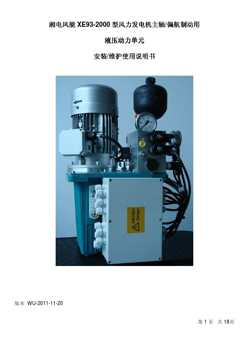
湘电风能XE93-2000型风力发电机主轴/偏航制动用液压动力单元安装/维护维护使用使用使用说明书说明书版本 WU-2011-11-20索引1.0 概要1.1 液压动力单元概述 (3)1.2 液压系统加压 (3)1.3 正常工作情况 (4)1.4 低温起动 (4)1.5 主轴制动系统 (5)1.6 偏航制动系统 (5)1.7 偏航紧急制动 (6)1.8 泄漏检测系统 (6)2.0 安装2.1 液压原理图 PE-112901.1 (7)2.2 电气接线盒 PE-112901.3 (8)2.3 液压站安装图PE-112901.2 (9)2.4 液压站图文说明……………………………………………………10-112.5 零部件清单PE094401.1 (12)3.0 连接液压连接液压站站3.1 液压接口 (13)液压油规格 (14)4.0 液压油规格5.0 开机起动5.1 加注液压油 (15)5.2 电机旋向 (15)5.3 液压系统排气 (15)6.0 维护6.1 维护周期 (16)6.2 液压系统卸压 (16)6.3 故障诊断 (17)7.0 液压站文件7.1 零部件订货须知 (18)1.0 概要1.1 液压动力单元概述此液压动力单元用于控制湘电风能XE93-2000型风力发电机主轴型风力发电机主轴、、偏航制动及1个液压顶升缸。
此液压动力单元包括以下主要部件此液压动力单元包括以下主要部件::容积为13L 的油箱 泵、电机总成集成了各种阀及压力开关的集成块 隔膜式蓄能器,运用于主系统 隔膜式蓄能器,运用于偏航系统1.2 液压系统加压电机在1500转/分钟时齿轮泵的排量为2.4L/min 。
启动电机,系统压力将升高。
压力传感器 8将发出4~20mA 的电信号。
当工作压力为180bar 时,发出15.52mA 的电信号,此时电机停转。
当压力降低至160bar 时,发出14.24mA 的电信号,此时电机将重新启动。
液压站TE130说明书
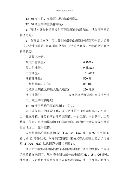
TE130双电机、双油泵二机制动液压站。
TE130液压站的主要作用是:1、可以为盘形制动器提供不同油压值的压力油,以获得不同的制动力矩。
2、在事故状态下,可以使制动器的油压迅速降到预先调定的某一值,经过延时后,制动器的全部油压迅速回到零,使制动器达到全制动状态。
主要技术参数:最大工作油压: 6.3MPa最大供油量:9升/min工作油温:15~65℃油箱储油量: 500升二级制动延时时间: 0~10s电液调压装置允许最大输入电流: 250毫安液压油牌号: N32抗磨液压油或22号透平油二、液压的结构原理TE130液压结构的原理见图1、图2。
为了确保提升的正常工作,液压站油箱中间用钢板隔开,相当于二个独立油箱,并带有两台叶片泵装置,一台工作,一台备用。
二泵替换工作时,由液动换向阀13自动换向,两台叶片泵装置放在油箱侧面地面上,便于维修。
安全制动部分由电磁阀G3、G4、G5、G6、减压阀9、溢流阀8、蓄力器12等件组成。
对单绳双筒提升来说又在此基础上增加了电磁阀18(G1、G2)以供调绳使用(见图1)。
液压站为盘形制动器提供了不同油压的油,油压的变化,由电液调压装置b来调节,这时安全制动部分的电磁阀G3、G4、G5带电,油路通,压力油通过管路分别进入盘形制动器,油压的变化,通过提升机司机控制电液调压装置的电流大小来实现的,从而达到了调节制动力矩的目的,电液调压装置原理见图3。
电液调压装置的作用如下:1、根据提升机的实际工作额定负荷,确定最大工作油压值Pmax 是通过手柄9来调定的。
2、通过改变动线图3的电流大小,实现系统油压的可调性。
压力油由K处进入,一路去溢流阀的C腔,另一路经精过滤芯14、节流螺塞13到G腔和溢流阀D腔(原溢流阀内的阻尼孔被堵住),当动线圈3的电流增加时,控制杆5下移,与喷嘴b的的距离缩短,G、D两腔的压力升高,溢流阀阀芯12下降,从R口溢出的油量减少,这样C腔的压力逐渐升高,阀芯12又处在新的平衡位置,动线圈3电流继续增大,当控制杆5向下的力大于喷头处向上的液动力时,控制杆5盖住喷头孔,这时K处油压最高,就是系统的工作压力。
YW系列电力液压块式制动器06[1].6.15
![YW系列电力液压块式制动器06[1].6.15](https://img.taocdn.com/s3/m/f72244e19e3143323968936f.png)
态(参见图2-4)。 制 动 拉 杆(退距调整杆) 防松螺母
防松螺母
A
A向 逆时针方向
防松螺母
拨销
紧定螺栓
●
● 补偿套
●
退距调整螺母
A
制动拉杆
●
●
图2-4 3.2.4将已打开的制动器平稳地移入安装位置,套住制动轮;然后将制动器地脚螺栓孔 对准安装基座上的螺栓孔,并松松地拧上地脚螺栓,然后按规定重新装好制动器,将制 动拉杆和弹簧拉杆就位,旋上防松螺母,力矩调整螺母装好。
ZPMC YW、YWB、YWZ5、YWZE系列电力液压块式制动器
用户手册
上海振华港机(集团)丰城制动器有限公司 江西华伍起重电器有限责任公司
版本号:3.4 版权所有,翻版必究 出版日期:2006.5.1
目 录
1.重要信息………………………………………………………………………(1) §1.1安全须知…………………………………………………………………(1) §1.2有限担保责任……………………………………………………………(1)
250
190
180
65 ±0.5
315 225(230)
220
±1.5
80
400
280
270
100
±2.5 ±3 0.8
500 335(340)
±0.8
325
130
630 425(420)
400
170
710 475(470) ±2 450 ±1.5 190 ±0.8 ±3.5 ±5 1.0
制动器具有瓦块自动随位、退距自动均等特点。根据用户需要,可带衬垫磨损自动 补偿装置使退距、力矩在使用过程中保持恒定,免去各种调整,基本达到免维护目的。 制动器可根据需要增设各种限位(联锁)开关,通过PLC控制,实现故障报警(联锁)、衬 垫磨损极限指示(联锁)等辅助功能。这些功能往往是现代化起重运输及高效装卸设备所 必须的。制动器还可根据需要增设手动释放装置及其安全联锁开关,用户在使用时十分 方便和安全。
ABB盘式制动器系统液压站设置说明
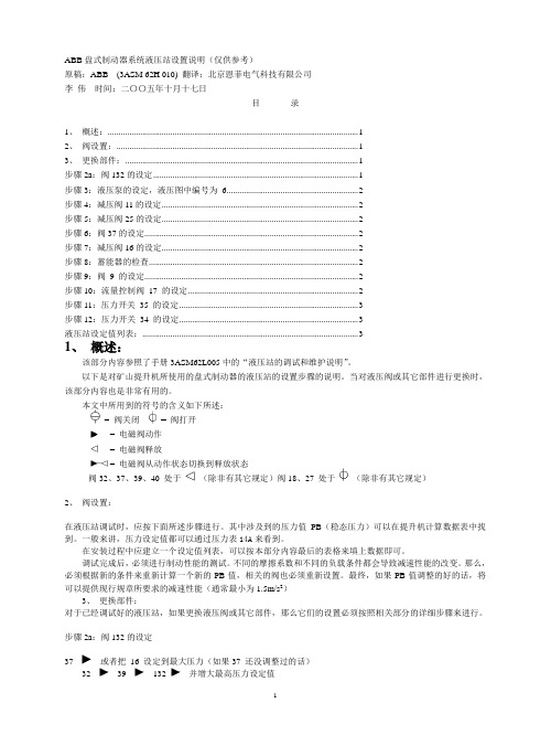
ABB盘式制动器系统液压站设置说明(仅供参考)原稿:ABB (3ASM 62H 010) 翻译:北京恩菲电气科技有限公司李伟时间:二〇〇五年十月十七日目录1、概述: (1)2、阀设置: (1)3、更换部件: (1)步骤2a:阀132的设定 (1)步骤3:液压泵的设定,液压图中编号为 6 (2)步骤4:减压阀11的设定 (2)步骤5:减压阀25的设定 (2)步骤6:阀37的设定 (2)步骤7:减压阀16的设定 (2)步骤8:蓄能器的检查 (2)步骤9:阀9 的设定 (2)步骤10:流量控制阀17 的设定 (2)步骤11:压力开关35 的设定 (3)步骤12:压力开关34 的设定 (3)液压站设定值列表: (3)1、概述:该部分内容参照了手册3ASM62L005中的“液压站的调试和维护说明”。
以下是对矿山提升机所使用的盘式制动器的液压站的设置步骤的说明。
当对液压阀或其它部件进行更换时,该部分内容也是非常有用的。
本文中所用到的符号的含义如下所述:= 阀关闭= 阀打开= 电磁阀动作= 电磁阀释放= 电磁阀从动作状态切换到释放状态阀32、37、39、40 处于(除非有其它规定)阀18、27 处于(除非有其它规定)2、阀设置:在液压站调试时,应按下面所述步骤进行。
其中涉及到的压力值PB(稳态压力)可以在提升机计算数据表中找到。
一般来讲,压力设定值都可以通过压力表14A来看到。
在安装过程中应建立一个设定值列表,可以按本部分内容最后的表格来填上数据即可。
调试完成后,必须进行制动性能的测试。
不同的摩擦系数和不同的负载条件都会导致减速性能的改变。
那么,必须根据新的条件来重新计算一个新的PB值,相关的阀也必须重新设置。
最终,如果PB值调整的好的话,将可以提供现行规章所要求的减速性能(通常最小为1.5m/s2)3、更换部件:对于已经调试好的液压站,如果更换液压阀或其它部件,那么它们的设置必须按照相关部分的详细步骤来进行。
电力液压盘式制动器使用说明

YPL1型电力液压盘式制动器结构及原理说明
一次弹簧力矩调整螺母 手动释放装置
推动器 手动释放限位开关
二次制动弹簧组件 单向液压阻尼缸
底座
二次弹簧力矩调整螺母 手动释放装 置固定螺钉
退距调整螺母 开闸释放限位开关 一次制动弹簧组件
均等装置
补偿套 制动拉杆
制动瓦
制动器工作原理:当机构驱动电机断电停止驱动时;推动器也同时断电并失去推力;一次制动弹簧力经杠杆和 制动瓦作用到制动盘上产生一次制动力矩;对机构进行第一步制动;二次制动弹簧在单向液压阻尼缸的反力作 用下缓慢下移释放;待机构完全停止后二次制动弹簧释放到位并将弹簧力施加到制动盘上产生二次制动力矩; 实施停车防风制动;当机构通电驱动时;推动器同时通电驱动并迅速产生足够的推力推起推杆此时单向液压 阻尼缸无阻尼作用;使制动臂向两侧外张;制动瓦制动覆面脱离制动盘;停止制动作用; 制动器可根据需要增设 紧急制动短路电磁阀;在遇到突发性大风或其它紧急情况时;电磁阀通电使阻尼缸短路;实现二次制动弹簧无阻 尼释放;进行快速紧急制动;
! 注意:推动器补偿行程不得小于10mm或护罩下端闭闸时不得位于红色区域。
制动器的使用 维护
11
4 退距均等的调整
制动衬垫 制动盘
两侧的均等杠杆
调整螺栓 联接板 背紧螺母
退距均等杠杆
调整方法:打开制动器通电或用手动释放装置;观察制动衬垫与制动盘的 间隙; 如发现两侧不均等;则拧松间隙小一侧的锁紧螺母;顺时针旋转调整 螺栓;边拧边观察;至两侧间隙均等后停止旋转;并拧紧锁紧螺母; 此装置 为自动均等装置;调整好后在使用过程中无需调整专利技术;
2 预防措施 正确安装和正确调整即可预防;
制动器的使用 维护
- 1、下载文档前请自行甄别文档内容的完整性,平台不提供额外的编辑、内容补充、找答案等附加服务。
- 2、"仅部分预览"的文档,不可在线预览部分如存在完整性等问题,可反馈申请退款(可完整预览的文档不适用该条件!)。
- 3、如文档侵犯您的权益,请联系客服反馈,我们会尽快为您处理(人工客服工作时间:9:00-18:30)。
JIANGXI AGRICULTURAL UNIVERSITY 本科毕业论文(设计)题目:常闭鼓式制动器学院:工学院*名:***学号: ********专业:机械设计制造及其自动化年级:机制082班指导教师:林金龙职称:讲师二0一二年五月摘要制动器可以分两大类,工业制动器和汽车制动器,汽车制动器又分为行车制动器(脚刹)和驻车制动器。
在行车过程中,一般都采用行车制动(脚刹),便于在前进的过程中减速停车,不单是使汽车保持不动。
若行车制动失灵时才采用驻车制动。
当车停稳后,就要使用驻车制动(手刹),防止车辆前滑和后溜。
停车后一般除使用驻车制动外,上坡要将档位挂在一档(防止后溜),下坡要将档位挂在倒档(防止前滑)。
使机械运转部件停止或减速所必须施加的阻力矩称为制动力矩。
制动力矩是设计、选用制动器的依据,其大小由机械的型式和工作要求决定。
制动器上所用摩擦材料(制动件)的性能直接影响制动过程,而影响其性能的主要因素为工作温度和温升速度。
摩擦材料应具备高而稳定的摩擦系数和良好的耐磨性。
摩擦材料分金属和非金属两类。
前者常用的有铸铁、钢、青铜和粉末冶金摩擦材料等,后者有皮革、橡胶、木材和石棉等。
块式制动器是一种的主要适用于起重运输机械的制动装置。
本论文着重介绍了其特点、关键零部件的选择或设计计算方法、主要性能参数。
除此之外还着重介绍了制动臂、等关键部件的设计参数及注意事项,同时细节方面对于制动器的静力矩也做了详细的计算设计。
关键词:制动块;制动器;制动瓦;制动轮AbstractBrakes can be divided into two categories, industrial brakes and automotive brakes, automotive brake is divided into brake (foot brake) and the parking brake. In the driving process, generally used brake (foot brake), to facilitate the process of deceleration in the forward stop, not just the car to remain intact. If the traffic Zhidongshiling when using the parking brake. When the car completely stopped, it has to use the parking brake (hand brake), to prevent the vehicle front and rear slip slide. After stopping the general addition to the parking brake, the uphill hanging in a stall to stall (after the slide to prevent), downhill to hang in the reverse gear (to prevent forward slip.) Mechanical moving parts to stop or slow down the resistance of the moment must be applied as the brake torque. Braking torque is the design, selection based on the brake, the size of the pattern and work by the mechanical requirements of the decision. Friction material used on brake (brake parts) directly affects the performance of the braking process, and the main factors affecting the performance of the working temperature and the temperature rise speed. Friction material should have high and stable friction coefficient and good wear resistance. Metallic and nonmetallic friction materials sub-categories. The former are commonly used cast iron, steel, bronze, and powder metallurgy friction materials, which have leather, rubber, wood and asbestos.Disc brake arm frame is a new major for the braking device handling equipment. This paper focuses on its characteristics, key components of the selection or design methods, the main performance parameters and some bench test results. Highlights in addition to the brake arm, loose brake components, etc. The key design parameters and considerations, while the details of the static torque for the brake has also done a detailed calculation of design.Keyword:shoe block;arrester;brake scotch;brake pulley目录1 绪论 (1)1.1制动器简介 (1)1.2 制动器工作原理 (1)2 制动器的种类和用途 (1)2.1制动器的用途 (1)2.2 制动器的种类 (2)2.2.1 根据制动器的构造形式分类 (2)2.2.2 根据操作情况分类 (4)2.2.3 根据制动器驱动方式形式分类 (5)3 块式制动器的构造 (5)3.1制动轮 (5)3.2 制动瓦块 (5)3.3制动衬料 (5)3.3.1 关于制动衬料的要求: (6)3.3.2 摩擦衬料的主要种类: (6)4 块式制动器的设计与选用 (6)4.1 毕业设计(论文)内容与技术参数: (6)4.1.1 确定制动瓦块的正压力 (8)4.1.2确定B点的力的大小; (8)4.1.3确定D点力的大小 (9)4.1.4确定弹簧力的大小 (9)4.1.5确定油泵需要的力 (9)4.2 制动瓦块的 (9)4.3 均等杠杆 (11)总结 (12)参考文献 (13)致谢 (14)1 绪论1.1 制动器简介制动器是使机械中的运动件停止或减速的机械零件。
俗称刹车、闸。
制动器主要由制架、制动件和操纵装置等组成。
有些制动器还装有制动件间隙的自动调整装置。
为了减小制动力矩和结构寸,制动器通常装在设备的高速轴上,但对安全性要求较高的大型设备(如矿井提升机、电梯等)则应装在靠近设备工作部分的低速轴上。
有些制动器已标准化和系列化,并由专业工厂制造以供选用.块式制动器,靠制动块压紧在制动轮上实现制动的制动器。
单个制动块对制动轮轴压力大而不匀,故通常多用一对制动块,使制动轮轴上所受制动块的压力抵消。
制动技术的发展,使制动系统成为集机械,电,液,材料,计算机技术与一体的现代化。
制动器的技术,应考虑到制动器的类型,性能如何满足配套主机的要求,以及可靠性和经济性。
制动器是具有使运动部件减速,停止或保持停止状态功能的装置。
集工作和安全装置于一体,是保障机器安全工作的重要部件。
制动器是用于机构或机器减速或使其停止运行的装置,有时也用做调节和限制机构或机器的运行速度,它是保证机构或机器安全正常工作的重要部件。
制动器根据工作状态可分为常闭式和常开式。
常闭式制动器靠弹簧或重力的作用经常处于紧刹状态,而机构工作时,可利用人力或松闸器使制动器松闸。
与之相反,常开式制动器经常处于松闸状态,只有施加外力时才能使其紧闸。
1.2 制动器工作原理制动器的工作原理是利用摩擦副中产生的摩擦力矩来实现制动作用,或者利用制力与重力的平衡,使机器运转速度保持恒定。
具体如下:制动器是依靠摩擦副间的摩擦而产生制动作用的,摩擦副中的一组与机构的固定机架相连。
另一组则与机构转动轴相连。
当机构起动时,使摩擦面脱开,机构转动件便可运转;当机构需要制动时,使摩擦面接触并压紧,这时摩擦面间产生足够大的摩擦力矩,消耗动能,使机构减速,直到停止运动。
制动状态还能阻止机构在外载荷作用下运动。
采用摩擦制动的优点是:机构制动平稳可靠,有时还可以根据需要调整制动力矩的大小。
2 制动器的种类和用途2.1 制动器的用途在起重机的各个机构中,制动器几乎是不可缺少的组成部分。
在起升机构中必须装设可靠的制动器,以保证吊重能停止在空中。
自重不完全平衡的起重伸臂也必须用制动器将它维持在一定的位置。
运行机构与回转机构也需要用制动器使它们在一定的时间或一定的行程内停下来。
对于在露天工作或在斜坡上运行的起重机,制动器还有防止风力吹动或下滑的作用。
只有速度很低、阻力很大的室内起重机的运行机构才可以不装设制动器。
某些起重机的起升机构还利用制动器来使物品以所要求的速度下降,例如汽车起重机、淬火起重机等。
综上所述,制动器的作用有如下三种。
1)支持保持不动2)停止用摩擦消耗运动部分的动能,以一定的减速度使机构停止下来。
3)落重将制动力与重力平衡,使运动体以稳定(恒定)的速度下降。
在起重机的各个机构中,制动器可以具有上述一种或几种作用。
在设计或选用制动器时,应充分注意制动器的任务以及对它的要求。
例如,支持制动器的制动力矩必须具有足够的储备,也就是应当保证一定的安全系数。
对于安全性有高度要求的机构需要装设双重制动器,例如运送熔化铁水包的起升机构,规定必须装设两个制动器,其中每一个都能安全地支持铁水包不致坠落。
对于落重制动器,则应该考虑散热问题,它必须具有足够的散热面积将重物的位能所产生的热量散去,以免制动器过热而损坏或失效。
2.2 制动器的种类2.2.1 根据制动器的构造形式分类a 带式制动器:利用挠性钢带压紧制动轮产生制动力矩。