智能穿戴天线规格书WAN2012F245C0X(X=2,4,6)_2012 L-Ant 2.4G Type-2,4,6 Ver.1
华为智能天线TD-LTE基站配置指南(01)
华为技术有限公司
地址:
深圳市龙岗区坂田华为总部办公楼
网址:
客户服务邮箱: support@
客户服务电话: 4008302118
邮编:518129
文档版本 01 (2014-01-28)
华为专有和保密信息
版权所有 © 华为技术有限公司
i
智能天线 TD-LTE 基站配置指南
前言
前言
概述
本文档以华为 TD-LTE 基站配置华为 FA/D 智能天线电调与权值为例,介绍了智能天线 电调与权值的配置方法,目的在于指导现场工程师完成 TD-LTE 基站智能天线的配置。 基站版本为 eNodeB V100R006C01。
读者对象
本文档主要适用于以下工程师: 现场工程师 网络规划工程师 站点维护员
2 智能天线配置概述 ......................................................................................................................... 5
2.1 智能天线配置前准备 ..................................................................................................................................... 5 2.2 LMT 配置方式说明 ........................................................................................................................................ 6 2.3 智能天线序列号编码规则 ............................................................................................................................. 7
诺基亚 ONT G-2425G-A(外部天线) 技术规格书说明书
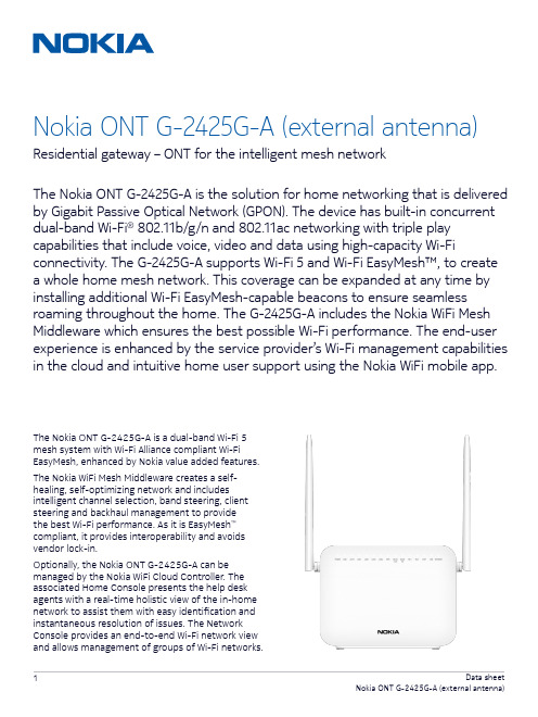
The Nokia ONT G-2425G-A is a dual-band Wi-Fi 5 mesh system with Wi-Fi Alliance compliant Wi-Fi EasyMesh, enhanced by Nokia value added features.The Nokia WiFi Mesh Middleware creates a self-healing, self-optimizing network and includes intelligent channel selection, band steering, client steering and backhaul management to provide the best Wi-Fi performance. As it is EasyMesh ™ compliant, it provides interoperability and avoids vendor lock-in.Optionally, the Nokia ONT G-2425G-A can be managed by the Nokia WiFi Cloud Controller. The associated Home Console presents the help desk agents with a real-time holistic view of the in-home network to assist them with easy identification and instantaneous resolution of issues. The Network Console provides an end-to-end Wi-Fi network view and allows management of groups of Wi-Fi networks.Nokia ONT G-2425G-A (external antenna)Residential gateway – ONT for the intelligent mesh networkThe Nokia ONT G-2425G-A is the solution for home networking that is delivered by Gigabit Passive Optical Network (GPON). The device has built-in concurrent dual-band Wi-Fi ® 802.11b/g/n and 802.11ac networking with triple play capabilities that include voice, video and data using high-capacity Wi-Ficonnectivity. The G-2425G-A supports Wi-Fi 5 and Wi-Fi EasyMesh™, to create a whole home mesh network. This coverage can be expanded at any time by installing additional Wi-Fi EasyMesh-capable beacons to ensure seamless roaming throughout the home. The G-2425G-A includes the Nokia WiFi Mesh Middleware which ensures the best possible Wi-Fi performance. The end-user experience is enhanced by the service provider’s Wi-Fi management capabilitiesin the cloud and intuitive home user support using the Nokia WiFi mobile app.This Nokia indoor ONT is designed to deliver triple play services (voice, video and data) to residential subscribers. Voice services are provided through two plain old telephone service (POTS) ports withan integrated analog telephone adapter (ATA)that converts voice traffic into Session Initiation Protocol (SIP). Connectivity to an existing public switched telephone network (PSTN) Class 5 switchis supported through SIP with direct interoperability of a variety of soft switches. Ethernet connectivity is available on four Gigabit Ethernet (GigE) ports, all of which have the ability to burst up to a full gigabit dynamically. Service providers can deliver video using IP packets (IPTV).Relying on dual-band Wi-Fi allows for support ofthe widest range of customer products. The IEEE 802.11ac standard enables gigabit speeds on many newer devices, while the widely supported 802.11b/g/n standard can simultaneously connect to legacy devices.Features• Four RJ-45 10/100/1000 Ethernet ports• Two POTS ports for carrier-grade voice services • Dual-band concurrent Wi-Fi: 2.4GHz and 5GHz • Wireless IEEE 802.11b/g/n: 2.4GHz• Wireless IEEE 802.11ac: 5GHz• Network Address Translation (NAT) and firewall • Voice interworking function from the analog POTS lines to the voice over IP (VoIP) and Ethernet layers • Two USB 2.0 host ports• Optics support received signal strength indication (RSSI)• Supports virtual private network (VPN) passthrough for Point-to-Point Tunneling Protocol (PPTP), Layer 2 Tunneling Protocol (L2TP) and IPSec• Port forwarding and demilitarized zone (DMZ)/ dynamic domain name system (DDNS)Benefits• EasyMesh enhanced by Nokia value added features • Integrates the ONT and wireless access pointfunctions to allow for one less device in the home • Delivers connectivity to Ethernet devices within the home• Supports full triple play services, including voice, video and data• Allows service-per-port configurations• Supports IP video distribution• Supports easy-to-use USB 2.0 connections for external disk drives and home network attached storage (NAS)• Delivers voice services using VoIP• Delivers video services efficiently with multicasting or unicasting• Facilitates network management using Nokia 5520 AMS• Flexible video delivery options of Ethernet or wireless to set-top boxes (STBs) Technical specifications Physical• Height: 131 mm (5.1 in)–Excluding antenna of 170 mm (6.7 in)• Width: 170 mm (6.7 in)• Depth: 30 mm (1.2 in)• Weight: 0.42 kg (0.92 lb)Installation• Desk mountable• Wall mountable with bracketOperating environment• Temperature: -5°C to 45°C (23°F to 113°F)• Relative humidity: 10% to 90%Power requirements• Local powering with 12 V input (feed uses external AC/DC adapter)• Dying gasp support• Power consumption: <24 WGPON uplinks• Wavelength: 1490 nm downstream, 1310 nm upstream• Line rate: 2.488 Gb/s downstream, 1.244 Gb/s upstream• GPON Encapsulation Method (GEM) mode support for IP/Ethernet service traffic• ITU-T G.984.3-compliant dynamic bandwidth reporting• ITU-T G.984.3-compliant Advanced Encryption Standard (AES) in downstream• ITU-T G.984.3-compliant forward error correction (FEC)• ITU-T G.988 Appendix 1 and Appendix 2 ONT Management Control Interface (OMCI)• Remote software image download• BOSA On Board (BOB) type laser, SC/APC connectorEthernet interfaces• 10/100/1000Base-T interface with RJ-45 connectors• Wi-Fi Protected Access (WPA) support, including pre-shared key (WPA-PSK) and WPA2• Forwarding• Ethernet port auto-negotiation or manual configuration with medium dependent interface/ medium dependent interface crossover(MDI/MDIX)• Virtual switch based on IEEE 802.1q virtual LAN (VLAN)• VLAN tagging/de-tagging per Ethernet port and marking/remarking of IEEE 802.1p • IP type of service/differentiated services code point (ToS/DSCP) to IEEE 802.1p mapping for untagged frames• Class of service (CoS) based on VLAN ID, IEEE 802.1p bit• Internet Group Management Protocol (IGMP)v2/v3 snoopingPOTS interfaces• Two FXS ports for VoIP service with RJ-11 connectors• Multiple codecs: ITU-T G.711, ITU-T G.729• SIP (RFC 3261)• ITU-T G.168 echo cancellation• Services: caller ID, call waiting, call hold, 3-way call, call transfer, message waiting indication• 3 ringer equivalence numbers (RENs) per line • Dual-tone multi-frequency (DTMF) dialing• Balanced sinusoidal ring signal, 55 V root mean square (RMS)WLAN interfaces• 2x2 MIMO on 802.11b/g/n• 2x2 MIMO on 802.11ac• 5 dBi external antenna• WPA, WPA-PSK/TKIP, WPA2, WPA2-PSK/AES• Media access control (MAC) filtersUSB interface• Two USB 2.0 interfacesResidential gateways• IPv4 and IPv6• Point-to-Point Protocol over Ethernet (PPPoE) and IP over Ethernet (IPoE)• NAT, DMZ and firewall• Dynamic Host Configuration Protocol (DHCP) and domain name system (DNS) proxy• IGMP proxy• Supports TR-069About NokiaWe create the technology to connect the world. Only Nokia offers a comprehensive portfolio of network equipment, software, services and licensing opportunities across the globe. With our commitment to innovation, driven by the award-winning Nokia Bell Labs, we are a leader in the development and deployment of 5G networks.Our communications service provider customers support more than 6.4 billion subscriptions with our radio networks, and our enterprise customers have deployed over 1,300 industrial networks worldwide. Adhering to the highest ethical standards, we transform how people live, work and communicate. For our latest updates, please visit us online and follow us on Twitter @nokia.Nokia operates a policy of ongoing development and has made all reasonable efforts to ensure that the content of this document is adequate and free of material errors and omissions. Nokia assumes no responsibility for any inaccuracies in this document and reserves the right to change, modify, transfer, or otherwise revise this publication without notice.Nokia is a registered trademark of Nokia Corporation. Other product and company names mentioned herein may be trademarks or trade names of their respective owners.© 2020 NokiaNokia Oyj Karaportti 3FI-02610 Espoo, Finland LEDs• Power • Link • Auth • LAN (1~4)• TEL (1~2)• VoIP• Wi-Fi Protected Setup (WPS) 2.4GHz/5GHz • WLAN 2.4GHz/5GHz • USB • InternetSafety and electromagnetic interference (EMI)• Protection of over voltage/currentRegulatory compliances• CE Mark • FCC Mark。
双频段体表/体外双模式可穿戴天线设计

doi:10.3969/j.issn.1003-3106.2024.05.022引用格式:沈飘飘,刘巾军,肖如奇,等.双频段体表/体外双模式可穿戴天线设计[J].无线电工程,2024,54(5):1255-1260.[SHENPiaopiao,LIUJinjun,XIAORuqi,etal.DesignofDual bandDual modeWearableAntennaforOn /Off bodyCommunications[J].RadioEngineering,2024,54(5):1255-1260.]双频段体表/体外双模式可穿戴天线设计沈飘飘1,刘巾军2,肖如奇1,杨 国1,齐世山1(1.南京理工大学电子工程与光电技术学院,江苏南京210094;2.陆军装备部驻南京地区第四军事代表室,江苏南京210007)摘 要:基于特征模理论分析方法,设计了一款2.45、5.8GHz频段的体表/体外双模式可穿戴天线。
在三角形的辐射贴片和接地面之间加载一段微带线,在2.45GHz引入一个具有全向辐射特性的新模式,加上三角形贴片本身在5.8GHz具有的定向辐射特性,组成了一个双频段双模式可穿戴天线。
天线的仿真结果表明,在低频处实现全向辐射特性,阻抗带宽为1.6%(2.45~2.49GHz),可用于体表通信模式;在高频处具有定向辐射特性,阻抗带宽为4.3%(5.67~5.92GHz),可用于体外通信模式。
关键词:可穿戴天线;特征模分析;体表通信;体外通信中图分类号:TN82文献标志码:A开放科学(资源服务)标识码(OSID):文章编号:1003-3106(2024)05-1255-06DesignofDual bandDual modeWearableAntennaforOn /Off bodyCommunicationsSHENPiaopiao1,LIUJinjun2,XIAORuqi1,YANGGuo1,QIShishan1(1.SchoolofElectronicandOpticalEngineering,NanjingUniversityofScienceandTechnology,Nanjing210094,China;2.TheFourthMilitaryRepresentativeOfficeofPLAArmyEquipmentDepartmentinNanjingRegion,Nanjing210007,China)Abstract:Basedonthetheoryofcharacteristicmode,adual modewearableantennaforon bodyandoff bodyoperationat2.45,5.8GHzisdesigned.Thedual banddual modewearableantennaisdevelopedbyintroducinganewomnidirectionalradiationmodeat2.45GHz,achievedbyloadingamicrostriplinebetweenthetriangularradiatingpatchandthegroundplane,combinedwiththedirectionalradiationpatternofthetriangularpatchitselfat5.8GHz.Simulationresultsshowthattheantennaprovidesomnidirectionalradiationatlowfrequencywithanimpedancebandwidthof1.6%(2.45~2.49GHz),suitableforon bodycommunication,anddirectionalradiationathighfrequencywithanimpedancebandwidthof4.3%(5.67~5.92GHz),suitableforoff bodycommunication.Keywords:wearableantenna;characteristicmodeanalysis;on bodycommunication;off bodycommunication收稿日期:2023-08-28基金项目:国家自然科学基金(62271257)FoundationItem:NationalNaturalScienceFoundationofChina(62271257)0 引言随着无线体域网的快速发展,对可穿戴天线结构和性能的要求越来越高,如何有效地实现体表通信[1]和体外通信[2]间信息的无缝传输至关重要,因此体表/体外双模式天线成为近年的研究热点。
MARUWA MWSL1252 GPS L1 天线规格书说明书

1.ScopeThis specification applies to the MARUWA MWSL1252 GPS L1 antenna which is intentionally designed to resonate in free-space at 1593.5MHz so that it can be tuned by the embedding configuration to the GPS L1 frequency: 1575.42MHz.The MWSL1252 part is designed for applications where packaging will cause a moderate level of down-tuning. Forapplications with a higher degree of detuning the MWSL1251 part should be selected.2.SpecificationsMinimum Typical Maximum UnitPart Number MWSL1251 (MARUWA dwg N o: MEFP125X0022A140101)Type Dielectric-loaded Quadrifilar HelixConnector Type Refer to embedding information / connection diagramsFree Space Frequency 1593.5MHzEmbedded Frequency 1575.42MHzPolarisation Right-hand Circular PolarisedIntegrated Gain (evaluation PCB)-3.0dBic at zenithBeamwidth >115DegreesBandwidth (3dB)15MHzAxial Ratio <1.5at zenithVSWR <2.0:1 2.3:1Impedance 50ΩOperating Temperature -402085°C Overall Dimensions Refer to mechanical drawings mmWeight 7.0grams3.DimensionsBasic MWSL1252 form:Rev.Date Description Approved Checked PreparedK.Inagaki F.Frimpong Product Specification (Preliminary)MARUWA Antenna ProductsDocument №MEPS-12520042150101MWSL12520103 Feb. 15Issue of the first edition O.Leisten Notes:1.MARUWA Europe assembly drawingMEFP125X022******* applies.2. Units in mm.3. For connection layout and pad-size, through-hole andconnector details please refer to pad layout and designationdefinitions.MWSL1252S form with loosely fitting translucent sleeve.Notes:1.MARUWA Europe assembly drawingMEFP125XS28A140101 applies.2. Units in mm.3. Transluscent sleeve unit: METC12XX028A140101 shownfitted but actually shipped separately.4. For connection layout and pad-size, through-hole andconnector details please refer to pad layout and designationMWSL1252R form with loosely fitting black radome cap.Notes:1.MARUWA Europe assembly drawingMEFP1252R04B140101 applies.2. Units in mm.3. Black cap/radome unit: METC120X158140101 shownfitted but actually shipped separately.4. For connection layout and pad-size, through-hole andconnector details please refer to pad layout and designation0103 Feb. 15Issue of the first edition K.Inagaki F.Frimpong O.Leisten Rev.Date Description Approved Checked Prepared4.Product DescriptionTypical Gain PatternThe MWSL1252 GPS L1 miniature dielectric-loaded antenna uses MARUWA’s distinctive materials technology to provide high circularly-polarised gain in a small size for particularly tightly integrated applications.It enables excellent GPS performance in such tightly integrated devices that require good positional eful gain uplift, due to near-field reflections, can be achieved throughinstallation according to MARUWA design guidelines.The MWSL1252 antenna has a sharp filtering response and is particularly suitable for applications where:*The device is hand-held, body-worn, or otherwise surrounded by materials of high relative dielectric-constant which would de-tune other antennas.* The antenna is installed in close proximity to other antennas sharing the same device housing and ground-plane: for example Bluetooth®, WiFi, LTE,WiMax and other cellular radio antennas.* The antenna must fit into a very small installation volume with close proximity to other components and little or no space available for a ground-plane.* The orientation of the device is random.* The antenna must be embedded into the device.The MWSL1252 antenna is balanced, which isolates it from the device ground enabling it to reject common-mode noise present on the device ground-plane. The construction and materials of the antenna constrain its near-field region to occupy a very small volume so that materials near theantenna cause negligible de-tuning effects. Therefore the antenna maintains its pattern and efficiency in the presence of dielectric loading. As a dielectric-loaded antenna the MWSL1252 has a stablefiltering effect; attenuating signals from common cellular and ISM frequency bands by as much as 30dB without external filtering.0849096180-96-90-84Elevation Gain (G θ) For Azimuth (φ)0264270276Azimuth Gain (G φ) for Elevation (θ)Rev.Date Description Approved Checked PreparedMARUWA Antenna ProductsDocument №MEPS-12520042150101MWSL12520103 Feb. 15Issue of the first edition K.Inagaki F.Frimpong O.Leisten A second mode of installation is one in which the MWSL1252 isembedded into the housing with features surrounding theantenna causing a moderate degree of down-tuning. Though it iselectrically isolated from the device ground plane, through theaction of an integrated balun, the MWSL1252 antenna can beexpected to increase efficiency by up to 100% when integratedinto a ground plane due to constructive near-field signalreflections. This product is generally used in a class of smallportable devices that have slim styling so that there is no spacefor a ground-plane that is laterally disposed with respect to theantenna-axis. It is therefore specified as embedded into aground-plane that is co-planar with the antenna axis.The MWSL1252 is designed for applications with embedding configurations that tune theantenna from the free-space resonant frequency of 1593.5MHz to the GPS L1 frequency of1575.42MHz. Such configurations include the co-planar ground-plane as shown above with10mm offset between the circuit-board copper-ground plane and the side of the antennatogether with further de-tuning caused by the plastic housing of the product.For applications with more tight embedding MARUWA offers the MWSL1251 part which is tuned to a free-space frequency of 1603.5MHz.The MARUWA MWSL1252 antenna is designed for two modes ofinstallation.The first (and preferred) configuration is as a stand-aloneextenally mounted antenna (outside of the housing) with the black-capradome fitted (MARUWA part number: METC120X0158140101). Theantenna can be incorporated into a stand-alone package with a co-axialconnector output as might be configured in a screw-on packageformat. In such a configuration the MWSL1252 part may be embeddedwithin a plastic over-moulding. Alternatively the antenna can beconnected to an internal circuit board using the connection pads butwith the product housing closing into the groove of the black capradome. As an another alternative the customer may choose to designa radome of a different style. Such a design must be implemented witha suitable low-loss material which has the same dielectric loadingeffect as the MARUWA METC120X0158141010 black cap/radome.Typical Impedance Response Typical Return Loss Response Filtering Response Rev.Date Description Approved Checked PreparedMARUWA Antenna ProductsDocument №MEPS-12520042150101MWSL1252O.Leisten Cellular 900GPS L1Cellular 18003G Rx ISM 2.4190021102170-29-32-30-40-38-46-40-3K.Inagaki F.Frimpong 0103 Feb. 2015Issue of the first edition Frequency (MHz)S 21 (dB)24002480860970157517001800-26-36A set of match loci for a typical MWSL1252antenna is shown as plotted on a Smith chartwhich is normalised to 50 . The dielectric-loaded structure of the antenna causes thematch characteristic not to change significantlywhen is close proximity to the human body. Forexample the |S 11| response is remarkablyunchanged as a human hand is brought as closeas 5mm from the antenna.This MARUWA dielectric-loaded antenna technology delivers a major advantage with regard toimmunity to de-tuning when brought into close proximity to human tissues and other "in-use"causes of dielectric loading. The MWSL1252 antenna retains efficiency and polarisation near the human body. Conventional antennas may lose 5-10dB of gain or efficiency in similarcircumstances of use.The frequency stability of the MWSL1252antenna is further illustrated in the graph ofreturn-loss magnitude (in dB)for fourdifferent levels of dielectric loading (mmoffset from a phantom hand). Once again itdemonstrates that minimal detuning occursuntil the antenna is within 10 mm of thephantom hand.Page 6/6Embedding Information Pad Layout and designation Pad Number Function 1Ground 2Signal 3GroundDimensionsmm ± 0.1A3.2B1.45C1.7D0.5E1.5F3.5G 3.5Ordering Guide for the MWSL1252 AntennaMaruwa PartDescription MOQ Pack Size MWSL1252 with PBC-feed connection.MWSL1252SMWSL1252 with sleeve (for embedded use).Please note that when MWSL1252S or MWSL1252R parts are ordered the sleeve/radome parts shall be delivered in separate packaging and will not be fitted to the MWSL1252 product. The radome and sleeve parts are designed to fit loosely.5.Notes1. The contents of this document assure the characteristics and quality of the antenna components themselves.2. Please ensure that they work correctly in the installed configuration and method of use of your equipment.Rev.Date Description Approved Checked PreparedProduct Specification (Preliminary)MARUWA Antenna ProductsO.Leisten Document №MEPS-12520042150101MWSL125201K.Inagaki MWSL1252R MWSL1252 with radome (for external use).400400400400400400MWSL1252Issue of the first edition 03 Feb. 2015 F.Frimpong A typical installation into a plastic housing isshown. It embodies the combination of ahand-soldered electrical connection to thehost PCB with mechanical support, in theform of plastic cradle-ribs, to implement ashock-resistant structure. Of course it isimportant to ensure that the assembly is notunder strain when the parts are fittedtogether. If accurate assembly jigs areavailable, the antenna can be soldered to theboard and thereafter the board-assemblycan be fitted into the housing. Alternativelythe MWSL1252 can be soldered to the boardwhich is itself fitted into the housing. Theinstallation is completed when the lid half ofthe housing, with the opposing antenna ribs,is fitted. Further installation information canbe obtained from MARUWA's integrationguideline documents.The "ground exclusion area" applies to all PCB layers. Ground-plane within this regiondegrades the 50Ωmatch.123F D EG AA B B C Ground。
智能穿戴专用天线WAN8010F245M0X(X=3~5_8010 M-Ant 2.4G Type-3~5 Ver.2

Remark : Bandwidth & Peak Gain was measured under evaluation board of page2
Part Number Information
WAN 8010
A A B C D E F B
F
C
245
D
M
E
0X(x=3~5)
F
Product Series Dimension L x W Material Working Frequency Feeding mode Antenna type
Terminal shall not be remarkably damaged. +85℃=>30±3min -40℃=>30±3min
Thermal shock
1. No visible mechanical damage 2. Central Freq. change :within ±6%
(TEL)+886 2 8911-0266 (Fax)+886 2 8911-0883 永昀科技股份有限公司
7
Phase Temperature(℃) Time(min)
1 2 3 4 +85±5℃ Room Temperature -40±2℃ Room Temperature 30±3 Within 3sec 30±3 Within 3sec
Temperature: 40±2℃ Humidity: 90% to 95% RH Duration: 1000±12hrs The chip shall be stabilized at normal condition for 2~3 hours before measuring.
NANO mXTEND 迷你高效蓝牙 Wi-Fi天线说明书

NANO mXTEND TM: MINIATURE AND HIGH EFFICIENCY BLUETOOTH/WI-FI ANTENNAUSER MANUALNANO mXTEND TM (NN02-101)NANO mXTEND TMMINIATURE AND HIGH-EFFICIENCY BLUETOOTH/WI-FIANTENNANN02-101NANO mXTEND TM | Bluetooth & Wi-Fi Operating range: 2400 – 10600 MHzBest for: 2400 – 2500 MHzDimensions : 3.0 mm x 2.0 mm x 0.8 mmWhat is the NANO mXTEND TM?The NANO mXTEND TM is the smallest Virtual Antenna® chip to date. Featuring a size of only 3 mm x 2 mm x 0.8 mm, this off-the-shelf chip antenna has been designed to fit almost every IoT device from entry-level to high-end products. The NANO mXTEND TM is enabled by Virtual Antenna® technology, thus featuring the unique properties of this class of products: easy to use; versatile, and broadly tunable. The NANO mXTEND TM is available for Bluetooth, Wi-Fi, Wi-SUN, and any wireless connectivity protocol operating in the 2.4 - 2.5 GHz band. Due to Ignion’s proprietary Virtual Antenna® technology, this chip antenna is non-resonant and therefore broadly tunable, enabling additional frequency bands to be supported by the same antenna part and released in the future.As with every other Virtual Antenna® chip, the NANO mXTEND TM is available through Ignion’s Antenna Intelligence Cloud tool, enabling predictable design and performance throughout the entire product development cycle. Moreover, the NANO mXTEND TM is built on a glass epoxy substrate, making its manufacturing broadly available and therefore resilient against shortage.Material: The NANO mXTEND TM antenna booster is built on a glass epoxy substrate.What is the NANO mXTEND TM used for?The NANO mXTEND TM is suitable for embedding an antenna into any wireless device requiring optimum performance in a small, cost-effective package for operating in the Bluetooth/Wi-Fi/Wi-SUN ISM 2.4 GHz frequency bands, including:▪Asset Trackers▪Smart Tags▪Earphones and Headsets ▪Wearables▪Logistic Trackers▪Health sensors ▪Animal Trackers▪Security Sensors▪Service Buttons▪Environmental Sensors ▪IoT Developer Kits▪Wireless Sniffing SensorsWhat differentiates the NANO mXTEND TM from other chip antennas?Like every other Virtual Antenna® product, the NANO mXTEND TM is frequency neutral, meaning that its frequency response is not determined by the antenna component but designed by the electronics engineer. Virtual Antenna® technology provides the broadest range of connectivity options with desired antenna performance in the smallest ever form factor. This unique technology enables the whole mXTEND TM range of components to become tiny, off-the-shelf, surface-mount (SMD) electronic chips while still providing connectivity with multiple frequency bands and meeting the requirements of most wireless devices’ architectures and form factors. Being non-resonant, the whole antenna performance can be customized through a shorter and easier design cycle by means of a matching circuit, while benefiting at the same time from a robust, reliable, and cost-effective manufacturing process because of the chip, SMD form factor. Also, the NANO mXTEND TM‘s architecture is not using ceramic materials to achieve miniaturization, which ensures a pervasive availability of raw materials thus making the supplychain resilient to shortage and price fluctuations.HOW TO EMBED A VIRTUAL ANTENNA®MECHANICAL SPECIFICATIONSASSEMBLY AND MANUFACTURINGPACKAGINGThe NANO mXTEND TM for Bluetooth/Wi-Fi 9 CORNER MOUNTING CONFIGURATION 9 MATCHING NETWORK 11 VSWR AND TOTAL EFFICIENCY 12 RADIATION PATTERNS, GAIN, AND EFFICIENCY 13 EDGE MOUNTING CONFIGURATION 14 MATCHING NETWORK 15 VSWR AND TOTAL EFFICIENCY 16 RADIATION PATTERNS, GAIN, AND EFFICIENCY 17 MECHANICAL SPECIFICATIONS 18 DIMENSIONS, TOLERANCES, AND RoHS 18 INK COLOR RANGE 18 RECOMMENDED FOOTPRINT FOR THE NN02-101 19 ASSEMBLY AND MANUFACTURING 21PACKAGING 23How to embed Virtual Antenna ®Design with Virtual Antenna ® in 1-2-3https://ignion.io/design-center/tutorials-webinars/STEP 2: Design your matching network1. Through a combination of inductors & capacitorsobtain 50 Ohms of antenna impedance to optimize the transfer of energy to your antenna2. It is critical to fine-tune your MN throughout theentirety the design process to achieve your desired frequency responseLook here for an example of a matching network for a Virtual Antenna ® product application via simulation Scan this QR code to see our videos highlighting these three easy stepsNeed further help? Easy start with Antenna Intelligence CloudDo you need more help with your antenna for your device?Use our Antenna Intelligence Cloud service and get your ready-to-test, proof-of-concept antenna design especially simulated for your platform free of charge 1, and in 24 hours .https://www.ignion.io/antenna-intelligence/1 Subject to terms and conditions here .Scan QR code to be taken to our AntennaIntelligence Cloud pageThe NANO mXTEND™ has been designed for Bluetooth/Wi-Fi connectivity at 2.4 GHz. An optimum tuning of this chip at the 2.4 GHz band is achieved through a matching network. Due to its versatility, the chip antenna component can be mounted both on the corner or on the center of an edge of the printed circuit board (PCB) of your wireless device just by changing the matching network. The table below includes a quick reference guide for the antenna specifications on a reference design of 80 x 40 mm, as well as the set-up matching network and performance for both a corner and an edge mounting configuration.QUICK REFERENCE GUIDETechnical Specs for the NANO mXTEND™ in the corner configuration: Technical features 2400 – 2500 MHzAverage Efficiency >55 %Peak Gain 2.4 dBiVSWR < 2.5:1Radiation Pattern OmnidirectionalPolarization LinearWeight (approx.) 0.01 g.Temperature -40 to +125 ºCImpedance 50 ΩDimensions3.0 mm x 2.0 mm x 0.8 mm(L x W x H)Table 1 – Technical Features. Measurements from the evaluation board (Figure 1) Technical Specs for the NANO mXTEND™ in the edge configuration: Technical features 2400 – 2500 MHzAverage Efficiency >65 %Peak Gain 2.4 dBiVSWR < 3.0:1Radiation Pattern OmnidirectionalPolarization LinearWeight (approx.) 0.01 g.Temperature -40 to +125 ºCImpedance 50 ΩDimensions3.0 mm x 2.0 mm x 0.8 mm(L x W x H)Table 2– Technical Features. Measurements from the evaluation board (Figure 4)CORNER MOUNTING CONFIGURATIONThe NANO mXTEND TM is ready and recommended for corner mounting in those devices where this region is available for antenna placement. This section details a corner mounting design on a reference ground plane of 80 mm x 40 mm including a clearance area of 5 mm x 5 mm (Figure 1). Other ground plane sizes and clearances can be implemented by adapting the matching network.MeasuremmA 80B 75C 40D 5E 5 F3Tolerance : ±0.2 mmD: Length of clearance area.Figure 1 - EB_NN02-101_c_BT. Evaluation board configured to provide operation at Bluetooth (2400 – 2500MHz).This product and its use are protected by at least one or more of the following patents and patent applications PAT. US 62/529032; and other domestic and international patents pending.MATCHING NETWORKThe NANO mXTEND TM antenna booster needs a matching network to ensure optimal performance in the 2.4 GHz – 2.5 GHz frequency range. This section presents a suitable matching network for the corner mounting configuration (Figure 7). Please note that different form factors, RF ground planes, and nearby components may require a different matching network.If you need assistance to design your matching network beyond this application note, please contact *****************, or if you are designing a different device size or a different frequency band, we can assist you in less than 24 hours. Please, try our free-of-charge1 Antenna Intelligence Cloud, which will get you a complete design report including a custom matching network for your device in 24h1. Additional information related to Ignion’s range of R&D services is available at: https://ignion.io/rdservices/2.4 GHz – 2.5 GHz8.7 nH LQW18AN8N7G808.2 nH LQW18AN8N2C805.8 nH LQW15AN5N8B80Figure 2 –Matching network implemented on the Evaluation Board (Figure 1) for covering Bluetooth from 2.4GHz to 2.5GHz.For an optimal result, the use of high-quality factor (Q) and tight tolerance components is highly recommended (e.g., Murata components with part numbers as shown in Figure 2). The antenna performance is always conditioned by its operating environment meaning that differences in the device, including differences in printed circuit board sizes, components near the antenna, displays, batteries, covers, connectors, etc. affect the antenna performance. Accordingly, placing pads compatible with 0402 and 0603 SMD components for a matching network as close as possible to the feeding point of the antenna element is highly recommendable. It is also recommendable to do this in the ground plane area, not in the clearance area. By tuning the matching network in your final design after your final surrounding components are in place (batteries, displays, covers, etc.) you will be able to optimize the antenna performance without changing the antenna part or the design.1 See terms and conditions for a free Antenna Intelligence Cloud service in 24h at:https://www.ignion.io/antenna-intelligence/VSWR (Voltage Standing Wave Ratio) and Total Efficiency versus Frequency (GHz).Figure 3 - VSWR and Total Efficiency for the 2.4 – 2.5 GHz frequency range as observed on the evaluation board EB_NN02-101_c_BT (Figure 1).2.4 – 2.5GHzNANO mXTEND™ ɳa 2400MHzɳa 2500MHz Min Max Av. ɳaOn the corner 54.9 57.1 54.9 63.2 60.1 Table 3 - Antenna efficiency comparison considering the evaluation board EB_NN02-101_c_BT (Figure 1).The NANO mXTEND TM operates at the required Bluetooth/Wi-Fi frequency spectrum with high-efficiency values. Please note that its high performance can be sustained even with a reducedclearance area.RADIATION PATTERNS, GAIN, AND EFFICIENCYMeasurement System Set-UpEvaluation Board in Plane XYθ = 90º Plane XY at 2450 MHzφ= 0º Plane XZ at 2450 MHzφ= 90º Plane YZ at 2450 MHz GainPeak Gain 2.4 dBiAverage Gain across the band 2.2 dBiGain Range across the band (min, max) 1.9 dBi <–> 2.4 dBi EfficiencyPeak Efficiency 75.4 %Average Efficiency across the band 71.9 %Efficiency Range across the band (min, max) 66.3 – 75.4 %Table 4 – Antenna Gain and total efficiency from the evaluation board (Figure 1) Bluetooth band. Measurements made in the STARLAB 18 anechoic chamber.EDGE MOUNTING CONFIGURATIONIn devices such as dual-hand gaming handhelds and landscape handheld devices, the center of the edge can be the ideal placement area for your chip antenna, This section details a design example and evaluation board (80 mm x 40 mm with 4 mm x 4 mm of ground clearance) in such an edge mounting configuration (Figure 4).MeasuremmA 80B 40 C5Tolerance : ±0.2 mmC: Length of clearance area.Figure 4 - EB_NN02-101_m_BT. Evaluation board providing operation at Bluetooth (2400 – 2500 MHz).MATCHING NETWORKBy simply changing the matching network, the NANO mXTEND TM can also deliver optimal performance in an edge mounting configuration. A suitable matching network for edge mounting in the reference board pictured above is shown in Fig.5. Please note that different form factors of your wireless device and its RF ground planes, and the proximity of other elements such as shields, covers, connectors and the like might result in the need for a fine-tuning of the matching network.If you need assistance to design your matching network beyond this application note, please contact *****************, or if you are designing a different device size or a different frequency band, we can assist you in less than 24 hours. Please, try our free-of-charge1 Antenna Intelligence Cloud, which will get you a complete design report including a custom matching network for your device in 24h2. Additional information related to Ignion’s range of R&D services is available at: https://ignion.io/rdservices/2.4 GHz – 2.5 GHz--0.4pF GJM1555C1HR40WB010.3pF GJM1555C1HR30WB010.3pF GJM1555C1HR30WB01Figure 5 –Matching network implemented in the Evaluation Board (Figure 4) for covering Bluetooth from 2.4GHz to 2.5GHz.To ensure optimal results, the use of high-quality factor (Q) and tight tolerance components is highly recommended (e.g. Murata components with part numbers as shown in Figure 5). The antenna performance is always conditioned by its operating environment meaning that differences in the device, including differences in printed circuit board sizes, components near the antenna, displays, batteries, covers, connectors, etc. affect the antenna performance. Accordingly, placing pads compatible with 0402 and 0603 SMD components for a matching network as close as possible to the feeding point of the antenna element is highly recommendable. It is recommended to do this in the ground plane area, not in the clearance area. By tuning the matching network in your final design after your final surrounding components are in place (batteries, displays, covers, etc.) you will be able to optimize the antenna performance without changing the antenna part, or the design.2 See terms and conditions for a free Antenna Intelligence Cloud service in 24h at:https://www.ignion.io/antenna-intelligence/VSWR (Voltage Standing Wave Ratio) and Total Efficiency versus Frequency (GHz).Figure 6 - VSWR and Total Efficiency for the 2.4 – 2.5 GHz frequency range configured to provide operation the evaluation board EB_NN02-101_m_BT (Figure 4).2400 – 2500 MHzNANO mXTEND™ ɳa 2400MHzɳa 2500MHz Min Max Av. ɳaOn the middle 60.1 63.6 60.1 77.3 71.7 Table 5 - Antenna efficiency comparison configured to provide operation the evaluation board EB_NN02-101_m_BT (Figure 4).The NANO mXTEND TM operates at the required Bluetooth/Wi-Fi frequency spectrum with high efficiency values. Please note that its high performance can be sustained even with the small5x5 mm clearance area.RADIATION PATTERNS, GAIN, AND EFFICIENCYMeasurement System Set-UpEvaluation Board in Plane XYθ = 90º Plane XY at 2450 MHzφ = 0º Plane XZ at 2450 MHzφ = 90º Plane YZ at 2450 MHzGainPeak Gain1.1 dBi Average Gain across the band0.85 dBi Gain Range across the band (min, max) 0.3 dBi <–> 1.1 dBiEfficiencyPeak Efficiency73.7 % Average Efficiency across the band69.6 % Efficiency Range across the band (min, max)70.0 – 73.7 %Table 6 – Antenna Gain and total efficiency from the evaluation board (Figure 4) Bluetooth band. Measurements made in the STARLAB 18 anechoic chamber.MECHANICAL SPECIFICATIONSDIMENSIONS, TOLERANCES, AND RoHSTOPSIDEBOTTOMDimensionmm DimensionmmA2.0 B3.0 C 0.25 D 1.0 E 0.5 F 1.3 G 0.6 H 0.8 I0.35J0.8Figure 7 - NANO mXTEND TM antenna booster dimensions and tolerances.The NANO mXTEND TM (NN02-101) antenna booster is compliant with the restriction of the use of hazardous substances (RoHS ). For more information, please contact **************.INK COLOR RANGEThe next figure shows the range of colors in the NANO mXTEND TM antenna booster:Acceptable color rangeRECOMMENDED FOOTPRINT FOR THE NN02-101See below the recommended footprint dimensions for the NANO mXTEND TM (NN02-101) antenna booster on the corner .MeasuremmA 1.0B 0.5C 1.3D 0.8 E0.15Tolerance : ±0.05mmFigure 8 - Footprint dimensions for the NANO mXTEND™ (NN02-101) antenna booster (on the corner).See below the recommended footprint dimensions for the NANO mXTEND T M (NN02-101) antenna booster in the middle .Tolerance : ±0.05mmMeasuremmA 1.875B 1.35C 0.5D 1.0E 3.15 F4.0Figure 9 - Footprint dimensions for the NANO mXTEND™ (NN02-101) antenna booster (on the middle).For additional support in the integration process, please contact *****************.ASSEMBLY AND MANUFACTURINGFigure 10 shows the back and front views of the NANO mXTEND TM(NN02-101) antennabooster.Figure 10 – Pads of the NANO mXTEND TM (NN02-101)antenna booster.As a surface mount device (SMD), the NANO mXTEND TM antenna booster is compatible withindustry standard soldering processes. The basic assembly procedure for the NANOmXTEND TM antenna booster is as follows:1. Apply a solder paste on the pads of the PCB. Place the NANO mXTEND TM antenna boosteron the board.2. Perform a reflow process according to the temperature profile detailed in Figure 11.3. After soldering the NANO mXTEND TM antenna booster to the circuit board, perform acleaning process to remove any residual flux. Ignion recommends conducting a visualinspection after the cleaning process to verify that all reflux has been removed.The figure below shows the soldering details obtained after a correct assembly process:Figure 11 - Soldering detailsNOTE (*): Solder paste thickness after the assembly process will depend on the thickness of the soldering stencil mask. A stencil thickness equal to or larger than 127 microns (5 mils) isrequired.The NANO mXTEND TM (NN02-101) antenna booster can be assembled following the Pb-free assembly process. According to the IPC/JEDEC J-STD-020C Standard, the suggested temperature profile is as follows:Phase Profile featuresPb-Free assembly (Sn Ag Cu) RAMP-UPAvg. Ramp-up Rate (Tsmax to Tp) 3 ºC / second (max.) PREHEAT- Temperature Min (Tsmin)- Temperature Max (Tsmax) - Time (tsmin to tsmax)150 ºC 200 ºC60-180 seconds REFLOW- Temperature (TL) - Total Time above TL (tL) 217 ºC60-150 seconds PEAK - Temperature (Tp) - Time (tp) 260 ºC 20-40 seconds RAMP-DOWNRate6 ºC/second max Time from 25 ºC to Peak Temperature8 minutes maxTable 7 – Recommended soldering temperatures.The next graphic shows the temperature profile (grey zone) for the NANO mXTEND TM antenna booster assembly process reflow ovens.Figure 12 – Temperature profilePACKAGINGThe NANO mXTEND TM (NN02-101) antenna booster is delivered in tape and reel packaging.Measure mm A0 3.6 ± 0.1 B0 7.5 ± 0.1 K0 2.5 ± 0.1 W 16.0 ± 0.3 P 8.0 ± 0.1 T 0.3 ± 0.05Figure 13 -Tape dimensions and tolerances.Reel Capacity : 2500 pcsMeasure Mm A 330 ± 1.0 G 16.4 ± 0.1 t max20.4 ± 0.1Figure 14 - Reel dimensions and capacity.Ignion products and solutions are protected by Ignion patents .All information contained within this document is property of Ignion and is subject to change without prior notice. Information is provided “as is” and without warranties. The copy or reproduction of this information without prior approval is prohibited.Ignion is an ISO 9001:2015 certified company. All our antennas are lead-free and RoHS compliant.ISO 9001: 2015 CertifiedContact:***************** +34 935 660 710BarcelonaAv. Alcalde Barnils, 64-68 Modul C, 3a pl. Sant Cugat del Vallés08174 BarcelonaSpainShenzhenTopway Information Building,2303 Room No.3369, Binhai Avenue, Nanshan District Shenzhen, Guangdong 518000China+86138****8470Tampa8875 Hidden River ParkwaySuite 300Tampa, FL 33637USA。
ARRL 天线书24版补充文件说明书

Supplemental Files – ARRL Antenna Book, 24th Edition Supplemental files are included with the downloadable content. They include additional discussion, related articles, additional projects, construction details and other useful information. All of these packages are available in the Supplemental Files directory and then organized by chapter. (Note: Chapters 2 and 28 have no supplemental files.)Chapter 1Supplemental Articles∙“Radio Mathematics” — supplemental information about math used in radio and a list of online resources and tutorials about common mathematics∙“Why an Antenna Radiates” by Kenneth MacLeish, W7TXChapter 3Supplemental Articles∙“Determination of Soil Electrical Characteristics Using a Low Dipole” by Rudy Severns, N6LF∙“Maxi mum-Gain Radial Ground Systems for Vertical Antennas” by Al Christman, K3LC∙“Radiation and Ground Loss Resistances In LF, MF and HF Verticals: Parts 1 and 2”by Rudy Severns, N6LF∙“Some Thoughts on Vertical Ground Systems over Seawater” by Rudy Severns, N6LF∙“The Case of Declining Beverage-on-Ground Performance” by Rudy Severns, N6LF ∙FCC Ground Conductivity Map SetChapter 4Supplemental Articles∙Antenna Book Table 4.3 expanded for other locations∙“Using Propagation Predictions fo r HF DXing” b y Dean Straw N6BVSupplemental Articles∙“An Update on Compact Transmitting Loops” by John Belrose, VE2CV∙“A Closer Look at Horizontal Loop Antennas” by Doug De Maw, W1FB∙“The Horizontal Loop —An Effective Multipurpose Antenna” by Scott Ha rwood, K4VWK∙“Small Gap-resonated HF Loop Antenna Fed by a Secondary Loop” by Kai Siwiak, KE4PT and R. Quick, W4RQ∙“Active Loop Aerials for HF Reception Part 1: Practical Loop Aerial Design, and Part 2: High Dynamic Range Aerial Amplifier Design,” by Ch ris Trask, N7ZWYChapter 6Supplemental Articles∙Appendix B — Manual Calculations for Arrays∙“A Wire Eight-Circle Array (for 7 MHz)” by Tony Preedy, G3LNP∙“A Study of Tall Verticals” by Al Christman, K3LC∙“Tall Vertical Arrays” by Al Christman, K3LC∙“The Simplest Phased Array Feed System —That Works” by Roy Lewellan, W7EL Note: EZNEC modeling files are in the separate ARRL Antenna Modeling Files folder with the downloadChapter 7Supplemental Articles∙5‐Band LPDA Construction Project and Telerana Construction Project∙“An Updat ed 2 Meter LPDA” by Andrzej Przedpelsi, KØABP∙Log Periodic‐Yagi Arrays∙"Practical High-Performance HF Log Periodic Antennas" by Bill Jones, K8CU∙“Six Band, 20 through 6 Meter LPDA” by Ralph Crumrine, NØKC∙"The Log Periodic Dipole Array" by Peter Rhodes, K4EWG∙“Using LPDA TV Antennas for the VHF Ham Bands” by John Stanley, K4ERO∙“Vee S haped Elements vs Straight Elements” by John Stanley, K4EROSupplemental Articles∙EZNEC Modeling Tutorial by Greg Ordy, W8WWVChapter 9Supplemental Articles∙“Designing a Shortened Antenna” by Luiz Duarte Lopes, CT1EOJ∙“A 6-Foot-High 7-MHz Vertical” by Jerry Sevick, W2FMI∙“A Horizontal Loop for 80-Meter DX” by John Belrose, VE2CV∙“A Gain Antenna for 28 MHz” by Brian Beezley, K6STI∙“A Low-Budget, Rotatable 17 Meter Loop” by Howard Hawkins, WB8IGU∙“A Simple Broadband Dipole for 80 Meters” by Frank Witt, AI1H∙“A Wideband Dipole for 75 and 80 Meters” by Ted Armstrong, WA6RNC∙“A Wideband 80 Meter Dipole” by Rudy Severns, N6LF∙“Broad-Band 80-Meter Antenna” by Allen Harbach, WA4DRU∙“Broad-banding a 160 m Vertical Antenna” by Grant Saviers, KZ1W∙“Inductively Loaded Dipoles”∙“Off-Center Loaded Antennas” by Jerry Hall, K1PLP∙“Th e 3/8-Wavelength Vertical —A Hidden Gem” by Joe Reisert, W1JR∙“The 160-Meter Sloper System at K3LR” by Al Christman, KB8I, Tim Duffy, K3LR and Jim Breakall, WA3FET∙“The ‘C-Pole’ —A Ground Independent Vertical Antenna” by Brian Cake, KF2YN∙“The Compact Vertical Dipole”∙“The Half-Delta Loop —A Critical Analysis and Practical Deployment” by John Belrose, VE2CV and Doug DeMaw, W1FB∙“The K1WA 7-MHz Sloper System”∙“The K4VX Linear-Loaded Dipole for 7 MHz” by Lew Gordon, K4VX∙“The Story of the Broadband Dipole” by Dave Leeson, W6NL∙“The W2FMI Ground-Mounted Short Vertical” by Jerry Sevick, W2FMI∙“Use Your Tower as a Dual-Band, Low-Band DX Antenna” by Ted Rappaport, N9NB, and Jim Parnell, W5JAWSupplemental Articles∙“A Compact Multiband Dipole” by Zack Lau, W1VT∙“A No Compromise Off-Center Fed Dipole for Four Bands” by Rick Littlefield, K1BQT ∙“A Triband Dipole for 30, 17, and 12 Meters” by Zack Lau, W1VT∙“An Effective Multi-Band Aerial of Simple Construction” by Louis Varney, G5RV (Original G5RV article)∙“An Experimental All-Band Non-directional Transmitting Antenna,” by G.L.Countryman, W3HH∙“An Improved Multiband Trap Dipole Antenna” by Al Buxton, W8NX∙“Broadband Transmitting Wire Antennas for 160 through 10 Meters” b y Floyd Koontz, WA2WVL∙“Cat Whiskers — The Broadband Multi-Loop Antenna” by Jacek Pawlowski, SP3L∙“End-Fed Antennas” by Ward Silver, NØAX∙“HF Discone Antennas”∙“HF Discone Antenna Projects” by W8NWF∙“Nested Loop Antennas” by Scott Davis, N3FJP∙“Revisiting the Double‐L” by Don Toman, K2KQ∙“Six Band Loaded Dipole Antenna” by Al Buxton, W8NX∙“The HF Discone Antenna” by John Belrose, VE2CV∙“The J78 Antenna: An Eight-band Off-Center-Fed HF Dipole” by Brian Machesney, K1LI/J75Y∙“The Multimatch Antenna System” by Chester Buchanan, W3DZZ∙“The Open Sleeve Antenna” by Roger Cox, WBØDGF∙“The Open-Sleeve Antenna” from previous editions∙“Two New Multiband Trap Dipoles” by Al Buxton, W8NX∙“Wideband 80 Meter Dipole” by Rudy Severns, N6LFSupplemental Articles∙“A 10 Meter Moxon Beam” by Allen Baker, KG4JJH∙“A 20 Meter Moxon Antenna” by Larry Banks, W1DYJ∙“Construction of W6NL Moxon on Cushcraft XM240” by Dave Leeson, W6NL∙“Having a Field Day with the Moxon Rectangle” by L.B. Cebik, W4RNL∙“Multimatch Antenna System” by Chester Buchanan, W3DZZ (see the Chapter 10 folder)Chapter 12Supplemental Articles∙“A Dipole Curtain for 15 and 10 Meters” by Mike Loukides, W1JQ∙“Bob Zepp: A Low Band, Low Cost, High Performance Antenna - Parts 1 and 2” by Robert Zavrel, W7SX∙“Curtains for You” by Jim Cain, K1TN (including Feedback)∙“Hands-On Radio Experiment #133 –Extended Double Zepp Antenna” by Ward Silver, NØAX∙“The Extended Double Zepp Revisited” by Jerry Haigwood, W5J H∙“The Extended Lazy H Antenna” by Walter Salmon VK2SA∙“The Multiband Extended Double Zepp and Derivative Designs” by Robert Zavrel, W7SX∙“The N4GG Array” by Hal Kennedy, N4GG∙“The W8JK Antenna: Recap and Update” by John Kraus, W8JKChapter 13Supplemental Articles∙“A Four Wire Steerable V Beam for 10 through 40 Meters” by Sam Moore, NX5ZSupplemental Articles∙“Station Design for DX, Part I” by Paul Rockwell, W3AFM∙“Station Design for DX, Part II” by Paul Rockwell, W3AFM∙“Station Design for DX, Part III” by Paul Rockwell, W3AFM∙“Station Design for DX, Part IV” by Paul Rockwell, W3AFM∙N6BV and K1VR Stack Feeding and Switching Systems∙“Generating Terrain Data Using MicroDEM” - from previous editions∙“All About Stacking” by Ken Wolff, K1EAChapter 15Supplemental Articles∙“2 × 3 = 6” by L.B. Cebik, W4RNL∙“A 6 Meter Moxon Antenna” by Allen Baker, KG4JJH∙“A 902-MHz Loop Yagi Antenna” by Don Hilliard, WØPW∙“A Short Boom, Wideband 3 Element Yagi for 6 Meters” by L.B. Cebik, W4RNL∙“A VHF/UHF Discone Antenna” by Bob Patterson, K5DZE∙“An Optimum Design for 432 MHz Yagis —Parts 1 and 2” by Steve Powlishen, K1FO∙“An Ultra-Light Yagi for Transatlantic and Other Extreme DX” by Fred Archibald, VE1FA, including the EZNEC model∙“Building a Medium-Gain, Wide-Band, 2 Meter Yagi” by L.B. Cebik, W4RNL∙“C Band TVRO Dishes” from previous editions∙“Development and Real World Replication of Modern Yagi Antennas (III) — Manual Optimisation of Multiple Yagi Arrays” by Justi n Johnson, GØKSC ∙“High-Performance ‘Self-Matched’ Yagi Antennas” by Justin Johnson, GØKSC∙“High-Performance Yagis for 144, 222 and 432 MHz” by Steve Powlishen, K1FO∙“LPDA for 2 Meters Plus” by L.B. Cebik, W4RNL∙“Making the LFA Loop” by Justin Johns on, GØKSC∙“Microwavelengths —Microwave Transmission Lines” by Paul Wade, W1GHZ∙“RF — A Small 70-cm Yagi” by Zack Lau, W1VT∙“The Helical Antenna—Description and Design” by David Conn, VE3KL∙“Three-Band Log-Periodic Antenna” by Robert Heslin, K7RT Y/2∙“Using LPDA TV Antennas for the VHF Ham Bands” by John Stanley, K4ERO∙“V-Shaped Elements versus Straight Elements” by John Stanley, K4EROSupport Files∙Model files and sample radiation patterns for Yagi designs by Justin Johnson, GØKSC (require EZNEC PRO/4 to reproduce the gain and other performancespecifications listed) These files are located in the ARRL Antenna ModelingFiles folder included with the download.Chapter 16Supplemental Articles∙5/8-Wavelength Whips for 2 Meters and 222 MHz∙“6-Meter Halo Antenna for DXing” by Jerry Clement, VE6AB∙“A 6m Hex Beam for the Rover” by Darryl Holman, WW7D∙“A 6 Meter Halo” by Paul Danzer, N1II∙“A New Spin on the Big Wheel” by L.B. Cebik, W4RNL and Bob Cerreto, WA1FXT ∙“A Simple 2 Meter Bicycle-Motorcycle Mobile Anten na” by John Allen, AA1EP∙“A Two‐Band Halo for V.H.F. Mobile” by Ed Tilton, W1HDQ∙“A VHF‐UHF 3‐Band Mobile Antenna” by J.L. Harris, WD4KGD∙“Bicycle-Mobile Antennas” by Steve Cerwin, WA5FRF and Eric Juhre, KØKJ∙“Introduction to Roving” by Ward Silver, NØAX∙“Omnidirectional 6 Meter Loop” by Bruce Walker, N3JO∙“Six Meters from Your Easy Chair” by Dick Stroud, W9SR∙“The DBJ-2: A Portable VHF-UHF Roll-up J-pole Antenna for Public Service” by Edison Fong, WB6IQN∙“The VHF-UHF Contest Rover Experience —Parts 1 and 2” by Greg Jurr ens, K5GJSupplemental Articles∙“A 12‐Foot Stressed Parabolic Dish” by Richard Knadle, K2RIW∙“A Parasitic Lindenblad Antenna for 70 cm” by Anthony Monteiro, AA2TX∙“A Portable Helix for 435 MHz” by Jim McKim, WØCY∙“A Simple Fixed Antenna for VHF/UHF Satellite Work” by L.B. Cebik, W4RNL∙“An EZ‐Lindenblad Antenna for 2 Meters” by Anthony Monteiro, AA2TX∙“Build a 2-Meter Quadrifilar Helix Antenna” by David Finell, N7LRY∙Converted C‐Band TVRO Dishes from previous editions∙“Double-Cross Antenna –A NOAA Satellite Downlink Antenna” by G erald Martes, KD6JDJ∙“EME with Adaptive Polarization at 432 MHz” by Joe Taylor, K1JT, and Justin Johnson, GØKSC∙“Inexpensive Broadband Preamp for Satellite Work” by Mark Spencer, WA8SME∙“L B and Helix Antenna Array” by Clare Fowler, V E3NPC∙“Quadrifilar Helix As a 2 Meter Base Station Antenna” by John Portune, W6NBC∙“Simple Dual-Band Dish Feed for Es’hail-2 QO-100” by Mike Willis, GØMJW; Remco den Besten, PA3FYM; and Paul Marsh, MØEYT∙Space Communications Antenna Examples from previous editions∙“The W3KH Quadrifilar Helix” by Eugene Ruperto, W3KH (plus two Feedback items)∙“Two‐Meter Eggbeater” by Les Kramer, WA2PTS and Dave Thornburg, WA2KZV∙“Work OSCAR 40 With Cardboard‐Box Antennas” by Anthony Monteiro, AA2TX∙“WRAPS: A Portable Satellite Antenna Rotator System” by Mark Spencer,WA8SME∙“WRAPS Rotat or Enhancements Add a Second Beam and Circular Polarization” by Mark Spencer, WA8SMESupplemental Articles∙“A 70-cm Power Divider” by Zack Lau, W1VT∙“Feeding Open-Wire Line at VHF and UHF” by Zack Lau, W1VT∙“Rewinding Relays for 12 V Operation,” by Paul Wade, W1GHZ∙“Increasing Side Suppression by Using Loop-Fed Directional Antennas” by Justin Johnson, GØKSCChapter 19Supplemental Articles∙“6 Meter 4 Element Portable Yagi” by Zack Lau, W1VT (plus separate element design drawing)∙“A 6-Meter Portable Yagi Antenna” by Scott McCann, W3MEO∙“A One Person, Safe, Portable and Easy to Erect Antenna Mast” by Bob Dixon, W8ERD∙“A Portable 2‐Element Triband Yagi” by M arkus Hansen, VE7CA∙“A Portable End-Fed Half-Wave Antenna for 80 Meters” by Rick Littlefield, K1BQT ∙“A Portable Inverted V Antenna” by Joseph Littlepage, WE5Y∙“A Simple and Portable HF Vertical Travel Antenna” by Phil Salas, AD5X∙“A Simple HF-Portable Antenna” by Phil Salas, AD5X∙“A Small, Portable Dipole for Field Use” by Ron Herring, W7HD∙“A Super Duper Five Band Portable Antenna” by Clarke Cooper, K8BP∙“A Two-Element Yagi for 18 MHz” by Martin Hedman, SMØDTK∙“An Off Center End Fed Dipole for Portable Operation on 40 to 6 Meters” by Kai Siwiak, KE4PT∙“Compact 40 Meter HF Loop for Your Recreational Vehicle” by John Portune, W6NBC∙“Fishing for DX with a Five Band Portable Antenna” by Barry Strickland, AB4QL∙“Getting the Antenna Aloft” b y Stuart Thomas, KB1HQS∙Ladder Mast and PVRC Mount∙“The Black Widow —A Portable 15 Meter Beam” by Allen Baker, KG4JJH∙“The Ultimate Portable HF Vertical Antenna” by Phil Salas, AD5X∙“The W4SSY Spudgun” by Byron Black, W4SSY∙“Tuning Electrically Short Antennas for Field Operation” by Ulrich Rohde, N1UL, and Kai Siwiak, KE4PT∙“Three-Element Portable 6 Meter Yagi” by Markus Hansen, VE7CA∙“Zip Cord Antennas and Feed Lines for Portable Applications” by William Parmley, KR8LChapter 20Supplemental Articles∙“A Compact Loop Antenna for 30 through 12 Meters” by Robert Capon, WA3ULH∙“A Disguised Flagpole Antenna” by Albert Parker, N4AQ∙“A 6-Meter Moxon Antenna” by Allen Baker, KG4JJH∙“An All-Band Attic Antenna” by Kai Siwiak, KE4PT∙“An Antenna Idea for Restricted Communities” by Cristian Paun, WV6N∙“Apartment Dweller Slinky Jr Antenna” by Arthur Peterson, W7CZB∙“Better Results with Indoor Antennas” by Fred Brown, W6HPH∙“Honey, I Shrunk the Antenna!” by Rod Newkirk, W9BRD∙“Small Hi gh‐Efficiency Loop Antennas” by Ted Hart, W5QJR∙“Short Antennas for the Lower Frequencies – Parts 1 and 2” by Yardley Beers, WØJF∙“Stealth 6-Meter Wire Beam” by Bruce Walker, N3JO∙Tuning Capacitors for Transmitting Loops∙“Using LPDA TV Antennas for the VHF Ham Bands” by John Stanley, K4EROSupplemental Articles∙“How To Build A Capacity Hat” by Ken Muggli, KØHL∙“Screwdriver Mobile Antenna” by Max Bloodworth, KO4TV∙“Table of Mobile Antenna Manufacturers” by Alan Applegate, KØBGChapter 22Supplemental Articles•“A Four-Way DFer” by Malcolm Mallette, WA9BVS•“A Fox-Hunting DF Twin Tenna” by R.F Gillette, W9PE•“A Receiving Antenna that Rejects Local Noise” by Brian Beezley, K6STI•“A Reversible LF and MF EWE Receive Antenna for Small Lots” by Michael Sapp, WA3TTS•“Active Antennas” by Ulrich Rohde, N1UL•“Beverages in Echelon”•“Design, Construction and Evaluation of the Eight Circle Vertical Array for Low Band Receiving” by Joel Harrison, W5ZN and Bob McGwier, N4HY•“Fl ag, Pennants and Other Ground-Independent Low-Band Receiving Antennas” by Earl Cunningham, K6SE•“Ferrite-Core Loop Antennas”•“Introducing the Shared Apex Loop Array” by Mark Bauman, KB7GF•“Is This EWE for You?” by Floyd Koontz, WA2WVL•“K6STI Low-No ise Receiving Antenna for 80 and 160 Meters” by Brian Beezley, K6STI•“Modeling the K9AY Loop” by Gary Breed, K9AY•“More EWEs for You” by Floyd Koontz, WA2WVL•“Rebuilding a Receiving Flag Antenna for 160 Meters” by Steve Lawrence, WB6RSE •“Simple Dir ection-Finding Receiver for 80 Meters” by Dale Hunt, WB6BYU•“The AMRAD Active LF Antenna” by Frank Gentges, KØBRA•“The Snoop-Loop” by Claude Maer, WØIC•“Transmitter Hunting with the DF Loop” by Loren Norberg, W9PYGSupplemental Articles∙“Coaxial RF Connectors for Microwaves” by Tom Williams, WA1MBA∙“Hands-On Radio: Open Wire Transmission Lines” by Ward Silver, NØAX∙“Hands-On Radio: SWR and Transmission Line Loss” by Ward Silver, NØAX∙“Hands-On Radio: Choosing a Feed Line” by Ward Silver, NØAX∙“Hands-On Radio: Feed Line Comparison” by Ward Silver, NØAX∙“Installing Coax Crimp Connectors” by Dino Papas, KLØS∙“Microwave Plumbing” by Paul Wade, W1GHZ∙“Multiband Operation with Open-wire Line” by George Cutsogeorge, W2VJN∙“My Feedline Tunes My Antenna” by Byron Goodman W1DX∙RF Connectors and Transmission Line Information ‐ ARRL Handbook∙Smith Chart supplement∙“The Doctor Is In: Yes, Window Line Can be Spliced —If You Must” by Joel Hallas, W1ZR∙“Using RG58 coaxial crimp connectors with RG6 cable” by Garth Jenkinson, VK3BBKChapter 24∙“Baluns in Matching Units” by Robert Neece, KØKR∙“Broadband Antenna Matching”∙“Coiled-Coax Balun Measurements” by Ed Gilbert, K2SQ∙“Compact 100-W Z-Match Antenna Tuner” by Phil Sala s, AD5X∙“Demystifying the Smith Chart” by Michael J. Toia, K3MT∙“Don’t Blow Up Your Balun” by Dean Straw, N6BV∙“Factors to be Considered in Matching Unit Design” by Robert Neece, KØKR∙“Hairpin Tuners for Matching Balanced Antenna Systems” by John Stanley, K4ERO ∙“High-Power ARRL Antenna Tuner” by Dean Straw, N6BV∙“Matching with Inductive Coupling”∙“Matching-Unit Circuit Comparison Table” by Robert Neece, KØKR∙“Optimizing the Performance of Harmonic Attenuation Stubs” by George Cutsogeorge, W2VJN∙“Tapered Lines” from previous editions∙“The AAT — Analyze Antenna Tuner —Program” by Dean Straw, N6BV∙“The EZ Tuner —Parts 1, 2, and 3,” by Jim Garland, W8ZR∙“The Quest for the Ideal Antenna Tuner” by Jack Belrose, VE2CV∙“Why Do Baluns Burn Up?” by Zack Lau, W1VTChapter 25Supplemental Articles∙“K5GO Half-Element Designs” by Stan Stockton, K5GO∙“Conductors for HF Antennas” by Rudy Severns, N6LF∙“Insulated Wire and Antennas” by Rudy Severns, N6LF∙“3D-Printed Coax-to-Wire Connection Blocks” by John Portune, W6NBCChapter 26Supplemental Articles∙“A One Person, Safe, Portable and Easy to Erect Antenna Mast” by Bob Dixon, W8ERD∙“Antenna Feed Line Control Box” by Phil Salas, AD5X∙“Homeowners Insurance and Your Antenna System” by Ray Fallen, ND8L∙“Installing Yagis in Trees” by Steve Morris, K7LXC∙“Is Your Tower Still Safe?” by Tony Brock‐Fisher, K1KP∙Ladder Mast and PVRC Mount∙“Lightning Protection for the Amateur Station, Parts 1, 2 and 3” by Ron Block, KB2UYT∙“Removing and Refurbishing Towers” by Steve Morris, K7LXC∙Rotator Specifications∙“The Care and Feeding of an Amateur’s Favorite Antenna Support —The Tree” by Doug Brede, W3AS∙“The Tower Shield” by Baker Springfield, W4HYY and Richard Ely, WA4VHMChapter 27Supplemental Articles∙“A Reflectometer for Twin-Lead” by Fred Brown, W6HPH∙“An Inexpensive VHF Directional Coupler” and “A Calorimeter for VHF and UHF Power Measurements”∙“Antenna Analyzer Pet Tricks” by Paul Wade, W1GHZ∙“Build a Super-Simple SWR Indicator” by Tony Brock-Fisher, K1KP∙“Improving and Using R-X Noise Bridges” by John Grebenkemper, KI6WX∙“Microwavelengths —Directional Couplers” by Paul Wade, W1GHZ∙“On Tuning, Matching and Measuring Antenna Systems Using a Hand Held SWR Analyzer” by John Belrose, VE2CV∙RF Power Meter (Kaune) support files∙“QRP Person’s VSWR Indicator” by Doug DeMaw, W1FB∙“Smith Chart Calculations”∙“SWR Analyzer Tips, Tricks, and Techniques” by George Badger, W6TC, et al∙“Technical Correspondence — A High-Power RF Sampler” by Tom Thompson WØIVJ (plus “More on a High-Power RF Sampler” by Thompson, two files)∙* “The Noise Bridge” by Jack Althouse, K6NY∙“Time Domain Reflectometry” from previous editions∙“The Gadget — An SWR Analyzer Add-On” by Fred Hauff, W3NZ∙“The No Fibbin RF Field Strength Meter” by John Noakes, VE7NI∙“The SWR Analyzer and Transmission Lines” by Peter Schuch, WB2UAQ∙“The Tandem Match —An Accurate Directional Wattmeter” by John Grebenkemper, KA3BLO (plus corrections and updates, four files)∙“Using Single-Frequency Antenna Analyzers” from previous editionsRepeater Antenna Systems Supplemental Articles144 MHz Duplexer CavitiesAntenna Fundamentals 1-1。
智能天线使用手册

1、引言1.1、智能天线的基本功能〕智能天线定义N 列取向相同的天线按照一定方式排列和激励,利用波的干涉原理形成预定波束的阵列结构天线。
〕智能天线基本功能智能天线可以通过改变各天线阵列的激励,其中激励包含幅值和相位,利用波的干涉原理形成预定波束。
同时,TD-SCDMA智能天线接入到TD-SCDMA基站后,通过基站的实时自适应信号处理算法,能够自动地产生多个窄波束方向图,实现对移动用户的波束跟踪,并自动地抑制干扰方向的副瓣电平。
从而降低了系统的干扰,提高了系统容量,达到空分多址的目的。
1.2、智能天线与GSM天线的区别〕结构组成区别智能天线由两个或以上天线阵列组成,而GSM系统天线只由一个天线阵列构成。
如图3、4所示:8列单极化智能天线GSM单极化天线图38通道双极化智能天线GSM双极化天线图41.2.2〕功能区别智能天线可以通过改变各天线阵列的激励,利用波的干涉原理形成预定波束。
而GSM天线只有一个阵列,其波束在设计时已确定,出厂后不可改变。
2、智能天线的分类2.1、全向天线在360°任意方位上均可进行波束扫描的智能天线阵列。
2.2、定向单极化天线特指采用单极化辐射单元,组成定向阵列,可以在特定方向内进行波束扫描的天线阵列。
2.3、定向双极化天线特指采用双极化辐射单元,组成定向阵列,可以在特定方向内进行波束扫描的天线阵列。
2.4、未来发展前瞻总结一期试验网的经验,业内对智能天线提出了“四化〞的要求,即双极化、宽带化、小型化和电调化。
根据目前智能天线行业发展状况,双极化与小型化已经基本实现,并大量应用于二期建网中;宽带化与电调化也在紧锣密鼓的进行中,并且是未来发展的一个重要趋势,除此之外,rru一体化智能天线也是未来发展的一项重要技术。
详细分析如下:20##初,我国十城市TD-SCDMA试验网络开始建设,当时,智能天线产品只有单极化板状定向智能天线阵和环状全向智能天线阵两种可供选择。
虽然基本上能够满足TD-SCDMA网络实现动态空间滤波对智能天线的电气性能要求,但随着网络建设的深入,在工程实施方面遇到了诸多亟待解决的挑战:1〕天线横截面积大,导致风载荷增加、安全等级下降;2〕天线体积大,公众时有抵触情节,选址难度增加;3〕网络优化需要闭站,且天线下倾角调节难度大;4〕智能天线与城市景观不融洽、不和谐。
- 1、下载文档前请自行甄别文档内容的完整性,平台不提供额外的编辑、内容补充、找答案等附加服务。
- 2、"仅部分预览"的文档,不可在线预览部分如存在完整性等问题,可反馈申请退款(可完整预览的文档不适用该条件!)。
- 3、如文档侵犯您的权益,请联系客服反馈,我们会尽快为您处理(人工客服工作时间:9:00-18:30)。
1.Electrical Specification
Remark : Bandwidth & Peak Gain was measured under evaluation board of page2
Part Number Information
WAN 2012 F 245 C 0X(X=2,4,6)
A B C D E F
2.
Recommended PCB Pattern
◆
Evaluation Board Dimension
◆
Layout Dimensions in Clearance area ( Size=3.0*5.0mm)
永昀科技股份有限公司WinWave Electronic Co., Ltd.
9F-2, No.82, Sec. 3, Beisin Rd., Sindian District, New Taipei City 23143, Taiwan(R.O.C.)
Electronic Co., Ltd.W IN W AVE
FootPrint (Unit : mm)
◆
Suggested Matching Circuit
◆
Tuning component : 0.6pF
永昀科技股份有限公司WinWave Electronic Co., Ltd.
9F-2, No.82, Sec. 3, Beisin Rd., Sindian District, New Taipei City 23143, Taiwan(R.O.C.)
Electronic Co., Ltd.W IN W AVE
3. Measurement Results
Return Loss
Radiation Pattern
Chamber Coordinate System
Y
4. Reliability and Test Condictions
1. No visible mechanical damage
1. No visible mechanical damage
5. Soldering and Mounting
Mildly activated rosin fluxes are preferred. The minimum amount of solder can lead to damage from the stresses caused by the difference in
coefficients of expansion between solder, chip and substrate. The
terminations are suitable for all wave and re-flow soldering systems. If hand soldering cannot be avoided, the preferred technique is the utilization of hot air soldering tools.
Recommended temperature profiles for re-flow soldering in Figure 1.
Products attachment with a soldering iron is discouraged due to the inherent process control limitations. In the event that a soldering iron must be
employed the following precautions are recommended.
‧Preheat circuit and products to 150℃
‧Never contact the ceramic with the iron tip
‧Use a 20 watt soldering iron with tip diameter of 1.0mm
‧280℃ tip temperature (max)
‧1.0mm tip diameter (max)
‧Limit soldering time to 3 sec.
6. Packaging Information
◆Tape Specification:
◆Reel Specification: (7’’, Φ180 mm)
7. Storage and Transportation Information
◆Storage Conditions
To maintain the solderability of terminal electrodes:
1. Temperature and humidity conditions: -10~ 40℃ and 30~70% RH.
2. Recommended products should be used within 6 months from the time
of delivery.
3. The packaging material should be kept where no chlorine or sulfur
exists in the air.
◆Transportation Conditions
1. Products should be handled with care to avoid damage or
contamination from perspiration and skin oils.
2. The use of tweezers or vacuum pick up is strongly recommended for
individual components.
3. Bulk handling should ensure that abrasion and mechanical shock are
minimized.
8. Revision Table。