ultramon使用手册
ultramon使用手册
ultramon使用手册Ultramon是一款强大的多显示器管理软件,可以帮助用户有效地管理多个显示器,并提供多种增强功能,以提升工作和娱乐体验。
以下是一份简单的Ultramon使用手册:1. 安装和设置:首先,您需要从Ultramon官方网站上下载并安装该软件。
安装完成后,您可以在Windows设置中打开Ultramon,并进行相关配置。
2. 连接显示器:在Ultramon主界面上,您可以看到当前连接的显示器列表。
确保您的显示器已正确连接到电脑,并打开显示器的电源。
3. 配置显示器:在Ultramon主界面上,您可以对每个显示器进行单独配置。
选择需要配置的显示器,然后调整其位置、大小和分辨率等参数。
确保每个显示器都正确显示所需的内容。
4. 扩展桌面:Ultramon支持将多个显示器合并为一个连续的桌面空间,方便您在一个屏幕上管理多个应用程序和窗口。
选择“扩展桌面”选项,然后选择您想要扩展的方向(横向或纵向)。
5. 配置多显示器设置:在Ultramon主界面上,您还可以配置多显示器设置。
选择“多显示器设置”,然后选择您想要的功能(如复制、扩展或仅在主显示器上显示)。
6. 调整显示设置:在Ultramon主界面上,您还可以调整显示设置,如亮度、对比度和颜色等。
选择“显示设置”,然后根据需要进行调整。
7. 退出Ultramon:当您完成多显示器配置后,可以退出Ultramon。
在Ultramon主界面上,选择“退出”选项即可。
以上是一份简单的Ultramon使用手册,希望能够帮助您更好地使用该软件。
如果您遇到任何问题或困难,请参考Ultramon的官方文档或寻求专业人士的帮助。
Monster TV VH-Dual F 说明书

用戶手冊使用手冊目錄初次使用-------------------------------------------------------------------------3 MonsterTV VH-Dual VH-F之特點------------------------------------------3 包裝盒附件確認--------------------------------------------------------------4 系統要求-------------------------------------------------------------------------5 安裝驅動程式------------------------------------------------------------------7 安裝應用程式------------------------------------------------------------------8 MonsterTV應用程式之介面---------------------------------------------10 MonsterTV之設定及使用功能------------------------------------------101.觀看電視及影片之功能------------------------------------------------112.電視節目及影片輸入之錄映功能-----------------------123.收音機之收聽及錄音設定---------------------------------124. 收音機及電視節目之預錄-------------------------------13感謝選購MonsterTVVH-F,本產品乃是以最新Video 技術來開發,以研發出多姿多彩的功能和高度兼容不同之系統。
UCAM-全中文教程

定义检查列表段
建立或更改检查列表
Resources(策略编辑) Unit (单位)
编辑 ucam.db 文件 覆盖 ucam 的策略文件 保存当前窗口版面
注:“*”所在的位置表示当前编辑所用的单位。Leabharlann Snap(锁定) Mode (模式)
没有定义
锁定格点 锁定 PADS 中心及线的断点 锁定线的任意一点
导出钻孔及锣带 导出 CAD 格式,包括 Gerber、EIE、Dxf、HPGL 等 导出网络数据 导出轨迹线 导出 AOI 资料 导出到光绘系统
打印
设定属性 设定颜色 制作自动检查列表 把频繁使用的步骤学习并记录下来 选项 制作 UCAM.db 文件 保存设置 设置工具栏 改变属性 修改单位 修改锁定模式 选择模式
2view显示菜单新建工作档打开旧档打开层编辑窗口合并工作档定义存盘的参数保存工作档保存成另一个工作档运行自动检查功能加载自动检测表调出导入文件对话框导入工作档扫描光绘系统推出ucam历史档返回到前一个画面大小平移画面刷新画面缩小放大画面显示选项显示格点鹰眼效果dcode显示错误测量数据查询数据显示矢量字体导入genesis工作档ucam使用手册子菜单zoom放大缩小options显示选项3edit编辑菜单子菜单aperturedcode与窗口同大放大两倍缩小两倍在窗口显示所有元素显示工作原点在blocks中编辑显示实体参考点元素以正常或零线显示选择实体切除实体拷贝实体粘贴实体清除实体删除实体编辑dcode修改实体实体属性管理实体属性编辑矢量字符光绘参数清除多余的d码合并d码切换选定的d码ucam使用手册4insert加元素菜单5undo撤销菜单6tools工具菜单子菜单analyze分析加pads加重叠的元素加线加框加矢量字符加条码打断线加机械零点加参考点撤销恢复清除内存中的指令提供撤销恢复的选项分析检验编辑加工提取网络制作测试架修理pcb板的生产参数分析生成pcb板快照铜箔面积钻孔信息分析工艺参数ucam使用手册verify分析editing编辑tooling加工netlist网络分析矢量弧蚀刻死角修补设计规范检测阻抗设计网络比较实体比较图形比较用参考层切除接连有开口的线或pads生成contours尺寸标注打散自动线pads转换flashpads镜像工作档手动线pads转换flashpads对位制作锣带建立所有网络建立层网络建立参考层网络生成测试数据生成网络轮廓清除网络数据依比例缩放制作分孔图优化钻孔路径用图象填充矢量填充削线路pads切字符制作阻焊制作泪滴ucam使用手册panel拼版6output导出7setup设定子菜单checklist检查列表拼版管理器阵列复制panel连接板边工作档制作板边script设定拼版环境导出钻孔及锣带导出cad格式包括gerbereiedxfhpgl导出网络数据导出轨迹线导出aoi资料导出到光绘系统打印设定属性设定颜色制作自动检查列表把频繁使用的步骤学习并记录下来选项制作ucamdb文件保存设置设置工具栏改变属性修改单位修改锁定模式选择模式定义检查列表段建立或更改检查列表ucam使用手册resources策略编辑unit单位注
Summon+ 3-Axis 稳定手持相机说明书

User Manual Publish in October 2016 3-Axis Stabilized Handheld CameraGuiLin FeiYu Technology Incorporated CompanyI Product OverviewII How to use Summon+1. Function introduction of buttons and ports2. Camera menu introduction3. Introduction of photographing and shooting4. Introduction of operating mode5. LED indicator instructions6. Reverse shooting7. Firmware upgrade8. Charging mode9. Initialization10. Operating exampleIII Product Parameters ENC ONTENTS12236677788810[2] Dust cover [3] Fill flash[4] 1/4 inch screw hole [5] USB port [6] Hand shank [16] Indicator [15] Control connecting base [14] Panning axis[12] Cross arm [13] Erecting arm [11] Rolling axis[19] Shutter [21] Micro SD port( Excluding card)[20] Microphone[23] HDMI interface[22] SD reading port [18] Function button [17] Joystick[10] Tilting axis[9] Camera back screen [8] Photo / Videoswitchover button [7] Camera[1] Camera lens I Product OverviewSummon+ is a controllable all-in-one camera with 3-axis stabilization function. It has simple and elegant structure and is easy to operate, the photographing and shooting are controllable so as to take stable HD videos and pictures. It has realized some functions including fixed point shooting, following shooting and time-lapse photography.[5][6][4][3]Tilting 310°Rolling 310°Panning 360°[21][23][22][10][12][14][11][13][17][16][15][18][19][9][7][8][4][2][1][20]II How to use Summon+1. Function introduction of buttons and ports1Install batteryPower on:Long press the function button until the green light up, then release it to turn on the gimbal.Power off:Long press the function button until the red light always on, then release it to turn off the gimbal.If the battery power is too low, the screen shall turn off automatically, please long press the function button for 3 seconds so as to make sure the unit completely powers off.Then you can recharge or replace the battery.Remove the hand shank and insert one 22650 battery into it.Single tap this button to switch below Photo mode and Video mode.Long press this button to open WiFi function, and long press again to turn off WiFi function. The default is Video mode.The function button can control power on or power off.2Power on / off!Connect to a computer with USB data cable so as to read the video and picture files in a SD card.SD reading portConnect with USB data cable by this port to upgrade firmware or charge the battery.Please refer to “Firmware upgrade”for the operation of firmware upgrade. Please refer to “Charging mode” for the charging mode.USB portHow to use Summon+Photo / Video switchover buttonMicro SD card *(Equipped by users)* Class10 high-speed micro SD card is recommendedUSB port2. Camera menu introductionControl the orientation of camera lensControl camera menu *Switch working mode or access camera menu.* Triple tap function button to access camera menu,the joystick can set the camera menu at this moment.Please refer to “Introduction of camera menu” and “Introduction of working mode”Function button The video files are named as MOV_xxxxx.mov, for example, "MOV_00001.mov"The picture files are named as IMG_xxxxx.jpgv, for example, "IMG_00001.jpg"Single tap this button to start or stop photographing or recording. In Photo mode, single tap this button to take a picture.In Video mode, single tap this button to start recording, and press again to stop recording.Double tap this button to turn on the fill flash, and double tap again to turn off the fill flash.ShutterJoystickJoystick Camera lensUp Down Left RightDown Up LeftRightJoystick Camera menu Up Down Left RightUpward selectionDownward selectionReturn to the previous menu / Exit Access the next menu / ConfirmHow to use Summon+Menu display in Video modeWhite Balance TimelapseTimelapse Duration Level Speed Vertical SpeedAUTOMedia Playback Movie Size 1080Field Of View Distortion Correct ON HSlow Motion OFF OFF OFFFollow Setting Date Stamp Date & TimeOFFInvert Mode OFF Language System Wi-Fi-Password ENTimelapseTimelapse Duration Level Speed Vertical SpeedOFF OFFFollow Setting Invert Mode Date Stamp Date & TimeOFFOFF ENLanguage System Wi-Fi-PasswordMenu display in Photo modePhoto Burst Media Playback Resolution Field Of ViewDistortion Correct ONHScheduled pictureOFF OFF Triple tap function button to access camera menuMedia PlaybackMenu introductionMovie SizeOnly display in Video mode. You can choose from below video sizes:Under the "VIDEO" or "JPG" option, click the " Photo / Video switchover button" enter the delete menu, you can choose to delete a single file or delete all files.Only display in Video modeOnly display in Photo mode1080P (60fps) / 1080P (30fps) / 720P (120fps) / 720P (60fps) / VGA (240fps) / 4K (25fps) / 4K (15fps) / 2.7K (30fps) / 1440P (30fps)16M (4508*3456) / 12M (4000*3000) / 8M (3264*2448) / 5M (2592*1944)Factory default setting is 1080P (60fps)Factory default setting is 16M (4508*3456)Field Of View You can choose from Wide, Medium and Narrow grades.The factory default setting is Wide.Distortion Correct Repair the distortion caused by camera lens to avoid the barrel shape distortion of pictures. Factory default setting is “On”.Slow Motion Open the slow motion function. Only display in Video mode except 4K videosizes. Factory default setting is “Off”.White Balance Tap to adjust the white balance. Only display in Video mode. Can be set to be Auto / Daylight / Cloudy / Fluor H / Tungsten, the boot-up default is “Auto”. Scheduled pictureOnly display in Photo mode. Factory default setting is “Off”. You can choose from below:Take a picture after 2 seconds 2S 10SDouble OffResolutionOnly display in Photo mode. You can choose from below :Tips: non-high-speed micro SD card is not available for 4K format shooting.Take a picture after 10 secondsPlay back recorded videosVIDEO JPGCheck the picturesUp DownTo the leftTo the right Check the previous video Check the next video Return to menu Play videos Check the previous picture Check the next picture Return to menuCheck picture informationTake the first picture after 10 seconds and take the second picture after 2 secondsDon’t use this functionJoystickVIDEOJPGPhoto Burst Only display in Photo mode. 3 / 5 / 10 pictures are settable for continuous shooting, factory default setting is Off.Press Shutter botton for continuous shooting after setting.TimelapseOpen the timelapse function and set the internal time for shooting two adjacent photos.You can choose from 3 sec / 5 sec / 10 sec / 30 sec /1 min / Off. Factory default setting is Off.Timelapse DurationSet the shooting time of time-lapse photography.Level Speed Open the panning axis rotation function and set the panning axis rotation speed fortime-lapse photography.The settable numerical range is -20 ← 0 → +20(“+”stands for clockwise rotation,“ -”stands for anticlockwise rotation),the bigger the number the faster the rotation speed, the maximum rotation speed is 360°/ 6 min, and the minimum is 360°/ 120 min.If the number increases by 1, the time needs for rotating 360° shall decrease by 6 minutes.If the number decreases by 1, the time needs for rotating 360° shall increase by 6 minutes. The time needs for rotating 360° between two numbers is as following table (“min” stands for minutes)There is no rotation when the number is set as 0.Vertical Speed Turn on the tilting axis rotation function to set the tilting axis rotation speed for time-lapse photography. Please refer to “Level Speed setting”.Invert ModeInvert the screen display after opening.Can be used for inversion shooting. Factory default setting is “Off”.Follow SettingYou can set the follow speed and follow dead zone of panning axis.DateStampThe shooting date and time shall be displayed on the picture after this function is opened. Settable options: Off / Date / Date & Time. Factory default setting is Off.Date & TimeCan set the current date, time and format. Turn the joystick to the right to successively select the date and time format desired to be modified, turn the joystick up to increase the numerical value while turn it down to decrease the numerical value.After setting all items, turn the joystick to the right to save the settings and return to the previous menu.Language Set the menu to be in English / Simplified Chinese / Traditional Chinese / German / French / Spanish / Portuguese. The factory default setting is English.SystemWIFI-Password Set WiFi password.Restore to the factory settingsFactory Reset Check the capacity and free space of SD cardCard Info System InfoCheck information related to the system1120min114min 108min 102min 96min 90min 84min 78min 72min 60min 66min 54min 48min 42min 36min 30min 24min 18min 12min 6min 234567891011121314151617181920Number TimeReset the tilting axis to initial orientation and initial modeOperation Double tapSingle tapFunctionExplanationPanning Mode / Lock Mode Panning and Tilting Mode Triple tapUnder panning and tilting mode, single tap to switch to lock modeAccess camera menu Control camera menu by the joystick ( Please refer to “Joystick” )Single tap to switch between panning mode and lock modeQuadruple tap ResetOperation instructions of function button3. Introduction of photographing and shootingPhotographing Switch to Photo mode by “Photo / Video switchover button”.Single tap “Shutter”button to photograph.Special modes: Photo Burst / Scheduled picture4. Introduction of operating modeShootingSwitch to Video mode by “Photo / Video switchover button”. Single tap “Shutter” button to start recording and press this button again to stop recording.Special mode: Slow Motion / Panorama shootingTimelapseAutomatically take a picture in the set time interval, panning axis moves by the set horizontal speed (or tilting axis moves by the set vertical speed), and automatically compose a video after shooting.( Please refer to “Actual Operations” for detailed operations )Panorama ShootingIn video mode, triple tap the "Shutter" button to start panorama shooting, heading axis will automatically rotate shooting. Shooting range: 360 ° Recording Time: 8sWorking modeOther functionsPanning mode The camera is allowed to pan left or right.Vertical tilts or rolls are disabled.Panning and Tilting mode The camera is allowed to pan left or right and tilt up and down. Rolls are disabled.Lock modeThe camera stays in its current orientation. All panning, tilting and rolls are disabled.ResetReset the tilting axis to initial orientation and initial mode.StandbyIn standby mode, keep in power-up state, the motor stops working, the indicator light flashes for three times, and single tap again to wake it up.Photo / Video switchover buttonShutterSingle tap again to wake it up, or triple tap to Long press StandbyColor Flashes IndicatorMode / StatusBlue Blue Panning mode Panning and Tilting mode Lock mode / InitializingBlue BlueInitialization failure / MalfunctionBlue Single Double Always on QuicklyTriple Standby 5. LED indicator instructions6. Inversion shooting7. Firmware upgradeTurn the hand shank to the upward side of camera to realize the inversion for shooting in the scenes with low angle.Upgrade steps(1)Please visit the official website to download therelevant programs for upgrading, including USB drive program, firmware upgrade software and product firmware, and install the relevant software, decompress the firmware files for standby application.Connect the USB cable with micro port as the above picture.Please upgrade the relevant firmware according to the operation(2)(3)Micro portUpgrade........PCUSB data cableUSB portHow to use Summon+After power off, connect the USB data cable to USB port, and connect with 5V USB power adapter by USB cable (equipped by user). Or take out the battery, and use the corresponding charger to charge the battery (equipped by user).The red indicator light is on during charging, and green light is on after the battery is fully charged.8. Charging5V USB power adapter (Equipped by user )10. Operating exampleTake time-lapse photography as an example:Place StillIn boot-up state, long press the Function Button until the red light flashes quickly to enter standby status, the blue light will flash 3times periodically.Lay the gimbal on a static flat surface and tripletap the Function Button. Initialization is successful when the blue light changes from constant on to flashing 3 times periodically.(1)(2)When the initialization failed, the LED indicator will flash quickly, repeat step (2) to reinitialize.Micro portUSB data cableUSB port(1) Install the battery, long press the function button for 0.5 second to power on.(2) Triple tap function button to access the menu.Access to the next menu or confirm Turn up to selectTurn down to selectReturn to the previous menu or exitFunction (1) There is small angular deviation between tilting angle and horizontal line after boot-up.(2) There is small angular deviation between rolling angle and horizontal line.(3) Under lock mode, panning angle drifts.Adjusting steps:( Initialize the gimbal )The horizontal angle needs to be adjusted whenever the following situations happen to the gimbal 9. Gimbal Horizontal Angle AdjustmentSingle tap the Shutter button to end theshooting in advance, the pictures shall automatically generate videos after shooting and can be previewed in “Media Playback”(3) To select “Timelapse”, turn the joystick to the right to access this interface, you can set the interval time of continuous pictures taken by time-lapse photography.For example, you can set it as 5 seconds. Turn the joystick to the right to save, and return to the previous menu.After enter “Timelapse”(4) To select “Timelapse Duration”, turn the joystick to the right to access this interface, you can select from unlimited / 5 / 10 / 15 / 20 / 30 / 60 minutes. The default is “unlimited”, i.e. no limit to the shooting time. Turn the joystick to the right to save, and return to the previous menu.(5) To select “Level Speed”, turn the joystick to the right to access this interface, setthe speed of panning movement, take “+15” as an example (“+” is for clockwise rotation, “-” is for anticlockwise rotation). Turn the joystick to the right to save, and return to the previous menu.(6) Single tap the Shutter after setting, panning axisshall rotate according to the set speed and take a picture for every 5 seconds. The pictures shall automatically generate videos after shooting.ShutterWhite Balance TimelapseTimelapse Duration Level SpeedVertical SpeedBack EnterWhite Balance TimelapseTimelapse Duration Level SpeedVertical SpeedBack EnterWhite Balance TimelapseTimelapse Duration Level Speed Vertical SpeedBack Enter白平衡持续时间缩时录影水平速度垂直速度BackEnterUnlimited 5Min 10Min 15Min0白平衡持续时间缩时录影水平速度垂直速度BackEnterOff3sec 5sec 10sec0level:000After enter “Timelapse Duration”After enter “Level Speed”9III Product ParametersWeight: 350g(Not including battery)97 mm81 mm232 mm143 mmTilting angle range310°Rolling angle range310°Panning angle range 360°Maximum control speed ±120°/s Battery model 22650Working voltage 3.7V ~ 4.2V Display screen 2.0 inch / 4:3, Resolution: 320x240ISO50~3200 , AutomaticGraph sensor16 mega pixels Lens specification 1 / 2.3”Lens field angle 95°Video resolution 4K@25FPS / 4K@15FPS / 2.7K@30FPS / 2.7K@15FPS / 1920x1440P@30FPS / 1080P@60FPS / 720P@120FPS / VGA@240FPSPhotograph resolution 16M (4608*3456) / 12M (4000*3000) / 8M (3264*2448) / 5M (2592*1944)Video formatMOV Picture formatJPGWorking environment Temperature: -10~+50℃ Humidity: 30%~80% Storage environment Temperature: -10~+150℃ Humidity: 30%~90%Memory card Maximum support 64GBSupport transfer rate of Class 10 Micro SD cardWIFIHigh-performance and low power consumption SDIO WiFi 2.4G, 802.11b/g/nFarthest distance is 10 meters in open and clear environmentAperture Sizef 2.810Prohibit any user for any illegal purpose. Users will be responsible for all behaviors of purchase and use products.The Company assumes no liability for any risks related to or resulting from the debug and use of this product (including the direct, indirect or third-party losses).For any unknown sources of using, we will not be at any services.The updating and changes of product firmware and program may cause changes in functiondescriptions in this user manual, please read the instructions carefully before upgrading the firmware and use the corresponding user manual.You can get the latest user manual from the official website: Feiyu Tech reserves the right to amend this manual and the terms and conditions of use the product at any time.AttentionD I S C L A I ME RPlease correctly assemble the product in accordance with the installation diagram. Please make sure the product is powered off when not in use.Please upgrade the firmware and program with the standard data cable.Package ListNameSummon+User manual22650 rechargeable batteryQuantity1111Portable bag11Warranty cardNameQuantityUSB cable (micro port, 50cm) 1Lens filter capFor more information, please visit our official website SupportEmail:**********************Create More Possibilities。
奥特威高级称重软件使用说明书V2.0

奥特威称重软件帮助文档
第三节 基础知识
称重术语 毛重:装满货物的车辆,车辆与货物的总重量 皮重/空重:空车重量 净重:货物的重量,净重=毛重-空重 扣重/扣率:水份或杂物的重量或百分比 实重:实重=净重-扣重或(净重*扣率)
软件术语 标准过磅:二次称重;称一次毛重,称一次空重,得出货物净重 简单过磅:二次称重;自动将两次过磅中重量大的做为毛重,重量轻的做为皮重 一次过磅:一次称重;一次将称出净重值。 预置信息:系统预置信息库,如皮重,收货单位,发货单位 全部记录:在相应时间条件内的所有称重记录 已完成记录:在相应时间条件内所有已得出净重值的记录 未完成记录:在相应时间条件内未得出净重值的记录
2、 运行称重管理系统 鼠标双击桌面上的“称重管理软件标准版”
3、 核对身份 登录对话框出现后,选择管理员,输入密码后点击“登录”按扭(注:初始 密码为:123)
4、 称取重量 车辆上秤台停稳后,然后单击“车号”输入框,输入车牌号,输入车牌号一 定要输入正确,因为第二次过磅时,系统是根据车牌号码自动查找并匹配车 辆的毛重与皮重,并据此计算出净重;同时输入其它信息,如收货单位、发 货单位等,若是空车则单击“空车”;如果是装了货则单击“重车”,确认信 息后,单击保存
4 / 31
奥特威称重软件帮助文档
第二节 快速入门
假定《高级称重管理软件》已经正确安装,且与仪表连接正常,整个系统已 经正常工作
操作步骤
1、 打开电脑 打开电源,启动 WINXP 操作系统(若发现电脑鼠标会不规则跳动,此时是因 为 XP 系统将仪表识别为了串口鼠标,此时可先将称重显示器电源拔下,重启 计算动软件——》帮助——》关于软件
3 / 31
奥特威称重软件帮助文档
Eudemon_200_操作手册_系统管理

目录第1章系统维护管理.............................................................................................................1-11.1 系统维护管理介绍.............................................................................................................1-11.2 配置文件管理.....................................................................................................................1-11.2.1 配置文件内容及格式...............................................................................................1-11.2.2 查看防火墙的当前配置和起始配置.........................................................................1-11.2.3 修改和保存当前配置...............................................................................................1-21.2.4 擦除配置文件..........................................................................................................1-21.2.5 配置文件使用..........................................................................................................1-31.3 维护调试............................................................................................................................1-41.3.1 配置防火墙名称和系统时钟....................................................................................1-41.3.2 正则表达式的使用...................................................................................................1-41.3.3 系统状态信息收集...................................................................................................1-71.3.4 网络连接的测试工具...............................................................................................1-71.3.5 系统调试功能..........................................................................................................1-91.4 补丁软件升级...................................................................................................................1-111.4.1 补丁软件升级........................................................................................................1-111.5 信息中心功能...................................................................................................................1-121.5.1 信息中心简介........................................................................................................1-121.5.2 信息中心配置........................................................................................................1-121.5.3 显示终端的配置....................................................................................................1-171.5.4 信息中心配置举例.................................................................................................1-171.6 日志维护..........................................................................................................................1-191.6.1 日志简介...............................................................................................................1-191.6.2 Syslog日志配置....................................................................................................1-201.6.3 二进制流日志配置.................................................................................................1-221.6.4 日志显示与调试....................................................................................................1-231.6.5 日志典型配置举例.................................................................................................1-231.7 VPN Manager适配..........................................................................................................1-261.7.1 VPN Manager简介................................................................................................1-261.7.2 Eudemon防火墙上的VPN Manager适配............................................................1-27第2章文件管理.....................................................................................................................2-12.1 文件系统............................................................................................................................2-12.1.1 文件系统简介..........................................................................................................2-12.1.2 目录操作.................................................................................................................2-12.1.3 文件操作.................................................................................................................2-12.1.4 存储设备操作..........................................................................................................2-22.1.5 文件系统提示方式...................................................................................................2-22.1.6 文件系统使用举例...................................................................................................2-22.2 FTP配置............................................................................................................................2-32.2.1 FTP简介.................................................................................................................2-32.2.2 FTP服务器配置.......................................................................................................2-42.2.3 FTP服务器的显示和调试........................................................................................2-52.2.4 FTP连接典型举例...................................................................................................2-52.3 TFTP配置..........................................................................................................................2-92.3.1 TFTP简介...............................................................................................................2-92.3.2 TFTP协议配置........................................................................................................2-92.4 XModem协议配置...........................................................................................................2-102.4.1 XModem协议简介.................................................................................................2-102.4.2 XModem协议配置.................................................................................................2-11第3章 NTP配置....................................................................................................................3-13.1 NTP协议简介....................................................................................................................3-13.2 NTP协议配置....................................................................................................................3-23.2.1 配置NTP工作模式.................................................................................................3-23.2.2 配置NTP身份验证功能..........................................................................................3-63.2.3 配置NTP验证密钥.................................................................................................3-63.2.4 配置指定密钥是可信的...........................................................................................3-73.2.5 配置本地发送NTP消息的接口...............................................................................3-73.2.6 配置NTP主时钟.....................................................................................................3-73.2.7 配置禁止/允许接口接收NTP消息..........................................................................3-83.2.8 配置对本地防火墙服务的访问控制权限..................................................................3-83.2.9 配置本地允许建立的sessions数目........................................................................3-93.3 NTP显示与调试.................................................................................................................3-93.4 NTP典型配置举例...........................................................................................................3-103.4.1 配置NTP服务器...................................................................................................3-103.4.2 配置NTP对等体举例...........................................................................................3-123.4.3 配置NTP广播模式...............................................................................................3-133.4.4 配置NTP组播模式...............................................................................................3-153.4.5 配置带身份验证的NTP服务器模式......................................................................3-16第4章 SNMP配置................................................................................................................4-14.1 协议简介............................................................................................................................4-14.1.1 SNMP协议介绍.......................................................................................................4-14.1.2 SNMP版本及支持的MIB........................................................................................4-14.2 SNMP配置........................................................................................................................4-34.2.1 启动或关闭SNMP Agent服务................................................................................4-34.2.2 使能或禁止SNMP协议的相应版本........................................................................4-34.2.3 配置团体名(Community Name).........................................................................4-44.2.4 配置/删除SNMP组................................................................................................4-44.2.5 添加/删除用户.........................................................................................................4-54.2.6 配置管理员的标识及联系方法(sysContact).......................................................4-54.2.7 允许/禁止发送Trap报文........................................................................................4-64.2.8 配置本地设备的引擎ID...........................................................................................4-64.2.9 配置Trap目标主机的地址......................................................................................4-74.2.10 配置防火墙位置(sysLocation)..........................................................................4-74.2.11 指定发送Trap的源地址.......................................................................................4-74.2.12 视图信息配置........................................................................................................4-84.2.13 配置消息包的最大值.............................................................................................4-84.2.14 配置Trap报文的消息队列的长度.........................................................................4-84.2.15 配置Trap报文的保存时间....................................................................................4-94.3 SNMP显示和调试..............................................................................................................4-94.4 SNMP典型配置举例........................................................................................................4-10第5章 RMON配置................................................................................................................5-15.1 RMON简介........................................................................................................................5-15.2 RMON配置........................................................................................................................5-35.2.1 使能/禁止RMON接口统计.....................................................................................5-35.2.2 统计表的配置..........................................................................................................5-35.2.3 历史控制表的配置...................................................................................................5-45.2.4 事件表的配置..........................................................................................................5-45.2.5 告警表的配置..........................................................................................................5-55.2.6 扩展告警表的配置...................................................................................................5-55.3 RMON显示和调试.............................................................................................................5-65.4 RMON典型配置举例.........................................................................................................5-75.5 RMON故障诊断与排除....................................................................................................5-10第6章 RMON2配置..............................................................................................................6-16.1 RMON2简介......................................................................................................................6-16.2 RMON2配置......................................................................................................................6-16.2.1 协议目录表的配置...................................................................................................6-16.2.2 主机控制表的配置...................................................................................................6-36.3 RMON2显示和调试...........................................................................................................6-46.4 RMON2典型配置举例.......................................................................................................6-56.5 RMON2故障诊断与排除....................................................................................................6-7第1章系统维护管理1.1 系统维护管理介绍系统维护管理主要包括以下几项内容:z配置文件管理z系统状态信息的收集和维护调试简单工具的使用z补丁软件升级z系统信息中心的维护管理z日志的维护和管理1.2 配置文件管理1.2.1 配置文件内容及格式配置文件为一文本文件,其格式如下:z以命令格式保存。
朗姆2.0电琴系统用户指南说明书
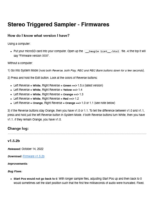
Stereo Triggered Sampler - FirmwaresHow do I know what version I have?Using a computer:Put your microSD card into your computer. Open up the __Sample List__.html file. At the top it will say "Firmware version XXX".Without a computer:1) Go into System Mode (hold both Reverse, both Play, REC and REC Bank buttons down for a few seconds).2) Press and hold the Edit button. Look at the colors of Reverse buttons:Left Reverse = White, Right Reverse = Green ==> 1.5.x (latest version)Left Reverse = White, Right Reverse = Yellow ==> 1.4Left Reverse = White, Right Reverse = Orange ==> 1.3Left Reverse = White, Right Reverse = Red ==> 1.2Left Reverse = Orange, Right Reverse = Orange ==> 1.0 or 1.1 (see note below)3) If the Reverse buttons stay Orange, then you have v1.0 or 1.1. To tell the difference between v1.0 and v1.1, press and hold just the left Reverse button in System Mode. If both Reverse buttons turn White, then you have v1.1. If they remain Orange, you have v1.0.Change log:v1.5.2bReleased: October 14, 2022Download:Firmware v1.5.2bImprovements:Bug Fixes:Start Pos would not go back to 0: With longer sample files, adjusting Start Pos up and then back to 0 would sometimes set the start position such that the first few milliseconds of audio were truncated. Fixed.Clicking when re-triggering a sample with long Fade settings: With longer Fade Up/Down Envelope times, re-triggering an already playing sample would prioritize low latency over the fade-down envelope, causing a click. In v1.5.2b the fade-down envelope is accelerated, adding a little bit of latency when re-triggering but removing the click. Setting the Fade Up/Down envelope time to fast removes the latency and clicking.Looping broken for very short samples when Perc Env is off: When Percussive Envelope was turned off, setting the sample length to be very short could make it not loop. Bug introduced in 1.5.2. Fixed.v1.5.2Released: October 8, 2022Improvements:Smaller firmware update files: The size of the firmware file has been reduced, making the firmware update .wav file smaller by about 57% (from 5:55 to 3:22).Bug Fixes:Long Fade In/Out Envelope times caused clicking in audio under certain circumstances: When the Fade In/Out Envelope Time was set longer than the Trigger Delay Time, firing a play trigger into a channel that's already playing audio would cause the audio to re-start before the fade out had completed, causinga pop or click in the audio. Another circumstance was if the Fade In/Out Envelope Time or PercussiveEnvelope Time was set longer than time between Start Pos and the actual start of sample data, playing a sample in reverse would result in extra silence or glitchy audio. Bug appeared in v1.5, fixed in v1.5.2.Recording Sample Rate not presevered across reboots: The Recording Sample Rate can be set in System Mode up to 96kHz. However, the next time the STS started up, the rate would be set back to44.1kHz, yet the System Mode lights would indicate it was still in 96kHz. One symptom was that sampleswould play back at the wrong pitch. Bug fixed in v1.5.2.v1.5.1bReleased: June 28, 2022New Features:Force Reload SD Card: Hold down four buttons: Bank 1, Bank 2, Rec Bank and Rec, for about 2seconds. Release the buttons when the startup sequence of lights displays.Bug Fix:Unrelated sample file played in certain circumstances: When Start Pos was high, within 0.5s of the end of the file, and Length was just under 50% (Percussive mode) but high enough such that a percussive burst longer than 0.5s was to be played, then the STS would overrun the sample data and play unrelated data (usually a previously played sample). Bug appeared in v1.5, fixed in v1.5.1b.(Note: v1.5.1a was not released)v1.5Released: June 6, 2022Download:Firmware v1.5New Features:Looping Fade Time: The STS can make a longer crossfade between the end and start of a loop(adjustable from 0.36ms to 250ms). This results in a smoother, click-free loop.LED Color Adjustment: You can now adjust the red, green, and blue amounts of each button, letting you match the colors between buttons. All new units ship pre-calibrated.Maximum Recording Rate: You can now record up to 96kHz.Auto Increment Sample Slot on Record: You can enable a mode that moves to the next sample slot each time you finish a recording that was started with the Rec Trigger jack.REC button flashes when you change sample slots: The REC button flashes red or white when you turn the REC Sample knob to indicate if the slot is full or empty.Bug Fix:PLAY button stayed dim red after a recording into an active slot: Fixed. The PLAY button nowindicates the selected sample slot is full immediately after recording into a previously empty slot.STS hangs on boot in some circumstances: Fixed. An issue where the STS could hang on boot while searching for missing sample files is now fixed.v1.4gReleased: August 4, 2020Download:Firmware v1.4gBug Fix:Sequencing Start Pos Glitch Fixed: Using a sequenced CV into Start Pos with gates/triggers into Play Trig would sometimes play the wrong start position if Length was < 50% and triggers were fired fast enough. Fixed.Intermediate versions:(1.4f released June 17, 2020. Improved performance of start-up sequence, and more types of "extended" wav file formats supported)v1.4eReleased: October 20, 2017Download: (not available, please use v1.4g)New Features:Reduced latency by pre-loading each sample file in a bank the first time each sample is played.Latency from trigger until audio output as low as 0.7ms (with Trigger Delay turned to 0, see below)The first time a sample is played after the bank is changed, latency is typically 5ms (may be moredepending on wav file's sampling rate and bit depth). Subsequent times the sample is triggered thelatency is 0.7msVariable "Trigger Delay": Edit + REC Sample knobCompensates for slew/lag when using a CV Sequencer with the Play Trig jack and the either theSample CV or 1V/oct jackThis feature also allows for latency reduction compared to prior firmware versions, which had a built-in delay of about 14msAfter receiving a trigger on the Play jack, the STS will wait the specified delay period before reading the 1V/oct and Sample CV jacks.To use: Press Edit and turn Rec Sample knob. The knob's numbers (1-10) correspond to a delayamount:PCB v1.0a: ranges from 0ms delay (knob at 1) to 14.3ms delay (knob at 10)PCB v1.1: ranges from 0ms delay (knob at 1) to 1.9ms delay (knob at 8), and extra-long delays of 4.1ms (knob at 9) and 8.2ms (knob at 10)Note: If upgrading to v1.4 causes your sequencer and STS to not play well together, set the Trigger Delay to "8" or higherMonitoring on/off per channel: Left and right channels can monitor the inputs separately.Pressing PLAY on one channel while monitoring is on will turn monitoring off for just that channel.Only works in Mono mode.Monitor LED blinks to indicate split monitoring.Typical use would be to patch Right OUT -> Left IN, then Left OUT -> mixer. Then record the right channel's playback.Start-up banks: Can set the default bank to be loaded at start-up.Hold down Edit + Bank 1 + Bank 2 + left PLAY (Save) for 1 second. Current bank selection will be saved as the default after power on.Envelopes can be turned off: Both percussive envelope and longer playback fade in/out envelopeTwo types of envelopes can be turned on or off:Percussive Envelopes: this is the decay-only envelope applied to playback when Length < 50% (actually an attack-only envelope when Reverse is on)Fade In/Out envelope: this is a very short envelope applied to any sample that's played withLength > 50%. It reduces clicks when starting, stopping, or looping playback.In System Mode, left channel Reverse button sets the envelope settings:Orange: Both envelopes enabled (default)Red: Percussive envelope disabledYellow: Fade In/Out envelopes disabledOff: Both envelopes disabledTurning off all envelopes is recommended when playing CV sample files (wav files with clocks/gates, sequencer CV, or slow LFO waveshapes, etc).Turning off Percussive Envelopes is interesting when doing "Granular" patches (see User Manual for example patches)Can toggle Percussive Envelope mode by turning left side Length to 0, and holding left side Reverse for 2 seconds: Reverse button will flash/flickerCan toggle Fade In/Out Envelope mode by turning left side Length to 100%, and holding left side Reverse for 2 seconds: Reverse button will flash/flickerAfter exiting System Mode, right side Length was set to 0, until the knob was moved. Fixed.Intermediate versions: (1.4beta-1 released October 13, 2017) (1.4beta-2 released October 17, 2017: changed Length behavior) (1.4c fixed sticky right length knob when exiting system mode) (1.4d fixed bugs that appeared in v1.4beta2) (1.4e fixed bugs that appeared in v1.3) (1.4f more filtering on 1V/oct jacks, and quantized mode plays better with tracking comp setting)v1.3Released: (beta released Sept 26, 2017)Download:Firmware v1.3 WAV fileNew Features:Drag-and-dropping WAV files to SD card works better:Adding WAV files to an existing folder now adds the files to the bank if there are empty slots.If there are no empty slots, the files can be added using Edit + Next File.On boot, the STS will try to fill empty slots in banks by searching in the bank's folder:If the bank contains files from multiple folders, the lowest-numbered sample file's folder is used.Adjust 1V/OCT jack offsetHold down Bank 1 + Bank 2 + Edit while tapping either REC or REC Bank button.REC shifts downwards, REC Bank shifts upwards.Settings are saved in memory (save using Edit + Save after making necessary adjustments).If there is a difference in pitch between the audio being monitored and playback, or a difference inplayback pitch between channels, then this may need to be adjusted. All units are calibrated in thefactory, but variations in power supplies and grounding configurations of cases may cause DC offsetto appear in a user's system.Fixes:Creating a folder with an exact color name in all lowercase added the folder twice. Fixed.Edit+Next File while in an empty slot now searches in the folder of the first filled slot.Released: (released Sept 8, 2017)Download:Firmware v1.2 WAV fileNew Features:Quantize 1V/oct jack added to System Mode. Each channel can be on/off seperately. Quantization is to semitones (12 notes per octave).In System Mode, tap Bank button for either channel to toggle state.Blue = On (jack is quantized to semitones)Orange = Off (jack is not quantized)Only effects 1V/oct jack, not the Pitch knobSetting is saved in settings file on microSD cardReset tracking compensaion to 1.0000Holding Edit+Rec+RecBankUpdating from v1.0 or v1.1 to v1.2 or later automatically sets tracking to 1.0000 the first time it isloaded (this is necessary because tracking is calculated differently in v1.2 and later)Auto Stop When Sample Changes: "Always keep playing" mode added. There are now three Auto Stop modes. The modes determine what happens when the sample is changed while a sample is being played.Red = Always Stop: The sample instantly stops playing. If looping is on, the new sample startsplaying immediately.Blue = Change When Looping: The sample keeps playing normally -- unless it's looping, in whichcase it stops immediately and the new sample starts.Green = Always Keep Playing: The sample keeps playing normally. If it's looping then the newsample begins when the previous sample reaches the end.Fixes:1V/octave tracking is tighter, +/-0.4 cents over C0-C3Changes:Faster entry into System Mode (2 seconds, instead of 4)Pitch knob's plateau around the center detent is larger, and gradually slopes away from center to make it easier to tune to other sourcesReleased: August 28, 2017Download:Firmware v1.1 WAV fileChanges:On boot, color of lights while index file is loading shows minor version numberIn System Mode, holding down Reverse displays firmware version on Reverse buttons (White, White =1.1)Fixes:Tapping Reverse after changing Channel Volume prematurely updated the Start Pos setting. Fixed.Scrub End setting for samples was not loaded after reboot until Edit button was pushed. Fixed.v1.0Released: August 10, 2017Initial ReleaseFeatures for future firmware versions:Allow for internally patching OUTs to INs for self-recordingSupport AIFF filesWrite index file in background, for faster boot time and "Edit+Save" time。
欧米龙 ultra微型基本开关D2QW说明书

Sealed long stroke sliding contact switch with reliable ON/OFF action in severe environmental conditions.•Extra-long stroke. (OT: 2.7 mm)•Clip contacts with highly reliable slide contact mechanism.•Sliding contact allows for quiet operating sound.•High temperature resistance and drip-proof structure for wide range of applications and environmental conditions.•Switch body conforms to IP67•RoHS CompliantOrdering InformationNote:Contact Omron for other terminal or lever configuration and for use in automotive applications. Model Number Legend:Specifications■ CharacteristicsNote:1.Data shown are of initial value.2.For pin plunger models, the above values apply for use at the free position, operating position, and total travel position. For models withlevers, the values apply at the total travel position.■RatingsNote:The resistive load ratings apply under the following test conditions: Ambient T emperature = 20±2°C,Ambient Humidity = 65±5%,Operating frequency = 30 operations/min.■Contact SpecificationsNote:Minimum applicable loads are indicated by N standard refer-ence values. This value represents the failure rate at a 60% (λ60) reliability level (JIS C5003).The equation λ60=0.5 x 10⁻⁶ / operations indicates that a failure rate of 1/2,000,000 operations can be expected at a reliability level of 60%Item SpecificationOperating speed 1 mm to 500 m/sOperating frequency30 operations/minInsulation resistance100 MΩ min. (at 500 V DC)Contact resistance100 mΩ max.Dielectric strength600 V AC, 50/60 Hz for 1 min between terminals of the same polarity1,500 V AC, 50/60 Hz for 1 min between current-carrying metal parts and ground, andbetween each terminal and non-current-carrying metal partsVibration resistance (See note 2)Malfunction: 10 to 55 Hz, 1.5-mm double amplitudeShock resistance (See note 2)Destruction: 1,000 m/s2 max.Malfunction: 300 m/s2 max.Ambient operating temperature–40 to 85 °C (with no icing)Ambient operating humidity95% max. (for 5 to 35°C)Degree of protection IEC IP67 (excluding the terminals on terminal models)Degree of protection against electric shock Class IProof tracking index (PTI)175Life expectancy Mechanical(30 operations/min)500,000 operations min.Electrical(20 operations/min)200,000 operations min. (at 30 V DC 0.1 A) 500,000operations min. (at 14 V DC 10 mA)Weight Approx. 0.7 g (for pin plunger models with terminals) Rated voltage (V)Resistive load30 V DC 14 V DC 0.1 A10 mAItem SpecificationSpecification SlideMaterial Gold platedMinimum applicable load(reference value)1 mA at 5 V DCEngineering Data■Mounting Structure and Reference Positions for Operating CharacteristicsNote:1.All units are in millimeters unless otherwise indicated.■TerminalsTerminal (H)■Contact FormSPST-NODimensions and Operating CharacteristicsNote:1.All units are in millimeters unless otherwise indicated.Mounting Hole Dimensions (Reference)Pin Plunger ModelsCharacteristic Models with posts OF max. 1.5 N {153 gf}OT ref.(2.7 mm)FP max.OPTTP max.9.2 mm 8.4±0.3 mm 5.9 mmSimulated Roller Leaf Lever ModelsD2QW-C073HCharacteristic Models with posts OF max. 1.5 N {153 gf}OT ref.(3.5 mm)FP max.OPTTP max.14.4 mm 12.0±0.5 mm 8.7 mmPrecautionsBe sure to read the precautions and information common to all Snap Action and Detection Switches, contained in the T echnical User’s Guide, “Snap Action Switches, T echnical Information” for correct use.■CautionsDegree of ProtectionIEC Publication 529, degree of protection IP67.Do not use this product in water. Although molded lead wire models satisfy the test conditions for the standard given above, this test is to check the ingress of water into the switch enclosure after submerging the Switch in water for a given time. Satisfying this test condition does not mean that the Switch can be used in water.Do not operate the Switch when it is exposed to water spray, or when water drops adhere to the Switch surface, or during sudden tempera-ture changes, otherwise water may intrude into the interior of the Switch due to a suction effect.Prevent the Switch from coming into contact with oil and chemicals. Otherwise, damage to or deterioration of Switch materials may result.Do not use the Switch in areas where it is exposed to silicon adhesives, oil, or grease, otherwise faulty contact may result due to the generation of silicon oxide.SolderingWhen soldering the lead wire to the terminal, first insert the lead wire conductor through the terminal hole and then conduct soldering. Complete soldering within 3 s using a soldering iron with a capacity of 50 W max. and a tip temperature of 300 °C max.Also, do not apply an external force to the Switch for 1 minute after the completion of soldering.Improper soldering involving an excessively high temperature or excessive soldering time may deteriorate the characteristics of the Switch.When using automatic soldering, solder at at 260 °C max and com-plete soldering with 5 seconds.Side-actuated (Cam/Dog) OperationWhen using a cam or dog to operate the Switch, factors such as the operating speed, operating frequency, push-button indentation, and material and shape of the cam or dog will affect the durability of the Switch. Confirm performance specifications under actual operation conditions before using the Switch in applications.■Correct UseMountingT urn OFF the power supply before mounting or removing the Switch, wiring, or performing maintenance or inspection. Failure to do so may result in electric shock or burning.For M3-screw mounting models, use M3 mounting screws with plane washers or spring washers to securely mount the Switch. Tighten the screws to a torque of 0.29 N·m {3 kgf·cm}. Exceeding the specified torque may result in deterioration of the sealing or damage.For models with posts, secure the posts by thermal caulking or by pressing into an attached device. When pressed into an attached device, provide guides on the opposite ends of the posts to ensure that they do not fall out or rattle.Mount the Switch onto a flat surface. Mounting on an uneven surface may cause deformation of the Switch, resulting in faulty operation or damage.Operating BodyUse an operating body with low frictional resistance and of a shape that will not interfere with the sealing rubber, otherwise the plunger may be damaged or the sealing may deteriorate.HandlingDo not handle the Switch in a way that may cause damage to the sealing rubber.When handling the Switch, ensure that pressure is not applied to the posts in the directions shown in the following diagram. Also, ensure that uneven pressure or pressure in a direction other than the operat-ing direction is not applied to the Actuator as shown in the following diagram. Otherwise, the post, Actuator, or Switch may be damaged, or the service life may be reduced.Wiring Molded Lead Wire ModelsWhen wiring molded lead wire models, ensure that there is no weight on the wire or that there are no sharp bends near the parts where the wire is drawn out. Otherwise, damage to the Switch or deterioration in the sealing may result.Using Micro LoadsEven when using micro load models within the operating range, inrush currents or surges may decrease the life expectancy of the Switch. Therefore, insert a contact protection circuit where neces-sary.MEMOOMRON ON-LINEGlobal - USA - Cat. No. B117-E-01Printed in USAOMRON ELECTRONIC COMPONENTS LLC55 E. Commerce Drive, Suite B Schaumburg, IL 60173847-882-228811/10 Specifications subject to change without noticeAll sales are subject to Omron Electronic Components LLC standard terms and conditions of sale, which can be found at /components/web/webfiles.nsf/sales_terms.html ALL DIMENSIONS SHOWN ARE IN MILLIMETERS.T o convert millimeters into inches, multiply by 0.03937. T o convert grams into ounces, multiply by 0.03527.。
- 1、下载文档前请自行甄别文档内容的完整性,平台不提供额外的编辑、内容补充、找答案等附加服务。
- 2、"仅部分预览"的文档,不可在线预览部分如存在完整性等问题,可反馈申请退款(可完整预览的文档不适用该条件!)。
- 3、如文档侵犯您的权益,请联系客服反馈,我们会尽快为您处理(人工客服工作时间:9:00-18:30)。
ultramon使用手册
Ultramon是一款强大的多显示器管理软件,它可以帮助用户有效地管理多个显示器,并提供多种增强功能,以提升工作和娱乐体验。
本篇文章将为您提供详细的Ultramon使用手册,帮助您了解和熟练使用该软件。
一、安装和设置
在开始使用Ultramon之前,您需要先进行安装和设置。
1. 下载和安装:您可以从Ultramon官方网站上下载安装程序,并按照提示进行安装。
安装完成后,您可以在Windows系统的任务栏中找到Ultramon的图标。
2. 主显示器设置:打开Ultramon控制面板,选择“主显示器”选项,并将您希望成为主显示器的屏幕拖放到该选项中。
3. 次要显示器设置:选择“次要显示器”选项,并按需求将您的次要显示器进行设置,包括位置、分辨率、旋转等。
二、任务栏扩展
Ultramon的任务栏扩展功能,可以让您在每个显示器上都有一个独立的任务栏。
这样可以更方便地管理正在运行的应用程序和快速切换窗口。
1. 开启任务栏扩展:在Ultramon控制面板中,选择“任务栏扩展”选项,并勾选“在每个显示器上显示独立任务栏”。
2. 自定义设置:您可以自定义每个任务栏的样式、颜色和显示项目。
在Ultramon控制面板的“任务栏扩展”选项中,点击“自定义设置”,根
据个人偏好进行调整。
三、窗口管理
Ultramon提供了强大的窗口管理功能,使您能够轻松管理和调整窗
口的位置和大小。
1. 拖曳窗口:通过Ultramon,您可以方便地将窗口从一个显示器拖
放到另一个显示器上,实现跨屏操作。
2. 最大化窗口:Ultramon的最大化功能可以让窗口跨越多个显示器
最大化,最大限度地利用屏幕空间。
3. 窗口快捷键:在Ultramon控制面板的“窗口管理”选项中,您可以
为常用的窗口操作设置快捷键,比如将窗口移动到指定的屏幕或调整
窗口大小。
四、壁纸和屏幕保护程序
Ultramon提供了丰富的壁纸和屏幕保护程序管理功能,让您可以个
性化设置每个显示器的壁纸和屏幕保护程序。
1. 多显示器壁纸:您可以在Ultramon控制面板的“壁纸”选项中,选
择不同的壁纸,并对每个显示器进行独立设置,实现个性化的多显示
器壁纸设置。
2. 屏幕保护程序:在Ultramon控制面板的“屏幕保护程序”选项中,您可以选择不同的屏幕保护程序并进行个性化设置。
同时,您还可以设置每个显示器是否启用屏幕保护程序。
五、快捷命令
Ultramon提供了一系列的快捷命令,让您更加高效地管理多个显示器,并快速切换显示模式。
1. 快速切换显示模式:通过Ultramon提供的快捷命令,您可以实现一键切换显示模式,比如将所有显示器设为克隆模式或扩展模式。
2. 聚焦显示器:在Ultramon控制面板的“快捷命令”选项中,您可以设置快速聚焦到指定的显示器,无需反复单击鼠标。
六、其他功能
除了以上介绍的功能,Ultramon还提供了许多其他实用的功能,如窗口规则、多屏幕游戏支持等。
1. 窗口规则:通过Ultramon的窗口规则功能,您可以通过设置特定的条件和操作,自动调整和管理窗口的位置和行为。
2. 多屏幕游戏支持:Ultramon可以帮助您解决多屏幕游戏中可能出现的问题,确保游戏在多个显示器上流畅运行。
结语
通过本篇文章,您已经了解了Ultramon的基本功能和使用方法。
希望这个使用手册对您在使用Ultramon时能够提供帮助,并最大限度地
发挥多显示器的优势。
如果您还有其他疑问或需要更深入的指导,请参考Ultramon官方网站提供的更详细的帮助文档和社区讨论。
祝您在使用Ultramon时取得良好的效果!。