三星贴片电容SGS报告-X5R X6S
x5r电容高温状态容值
x5r电容高温状态容值X5R电容是一种电子元件,属于贴片陶瓷电容的一种,具有特定的温度特性和容量变化范围。
在高温状态下,X5R电容的容值会发生变化,这是其固有的特性之一。
以下是对X5R电容高温状态容值的详细说明。
一、X5R电容的基本特性X5R电容是一种具有温度补偿功能的陶瓷电容,其名称中的“X”代表最低工作温度为-55℃,“5”代表最高工作温度为85℃,“R”代表容量随温度变化的最大变化量为±15%。
因此,X5R电容能够在-55℃~+85℃的温度范围内正常工作,并且其容量变化范围在±15%以内。
这种电容具有体积小、重量轻、价格便宜、可靠性高等优点,在电子设备中得到了广泛应用。
二、高温对X5R电容的影响在高温状态下,X5R电容的容值会发生变化。
一般来说,随着温度的升高,电容的容值也会增加。
这是因为陶瓷电容的容量与其介电常数成正比,而介电常数会随着温度的变化而变化。
当温度升高时,介电常数增加,导致电容的容值也相应增加。
但是需要注意的是,当温度超过一定范围时,电容的容值变化可能会超出±15%的范围,导致电容性能下降甚至失效。
三、X5R电容高温状态容值的变化规律X5R电容高温状态容值的变化规律与其温度系数有关。
温度系数是指单位温度变化时电容容值的相对变化量。
对于X5R电容来说,其温度系数一般为正值,即随着温度的升高,电容的容值也会增加。
但是需要注意的是,不同厂家、不同型号的X5R电容其温度系数可能有所不同,因此在实际应用中需要根据具体情况进行选择。
四、如何减小高温对X5R电容的影响为了减小高温对X5R电容的影响,可以采取以下措施:1.选择合适的电容型号和规格。
在选择X5R电容时,需要根据实际应用场景选择合适的型号和规格,确保其能够在所需的工作温度范围内正常工作。
2.控制环境温度。
在使用X5R电容时,需要尽可能控制环境温度,避免温度过高导致电容性能下降或失效。
3.采用散热措施。
三星陶瓷电容规格书
1.0
1.0
1.5
1.0 1.2 1.5 1.8
1.0 1.2 1.5 1.8
1.1 1.3 1.6 2.0
Capacitance Step
2.2
2.2
3.3
2.2 2.7 3.3 3.9
2.2 2.7 3.3 3.9
Symbol D G I J K
Rated Voltage(Vdc) 200V 500V 1000V 2000V 3000V
Multilayer Ceramic Capacitor
●7 THICKNESS OPTION
Symbol N A B C D E
Description of the Code Standard thickness (please refer to standard thickness table on next page) Thinner than standard thickness Thicker than standard thickness Standard Thickness High Q ( Low ` D.F ` ) Sn-100% (High-Q) Sn-100% (General)
● Application - High Frequency Circuit(Tuner, VCO, PAM etc) - General Power Supply Circuit(SMPS etc) - DC-DC Converter - General Electronic Circuit
Capacitance Change (ΔC : %)
± 15 ± 15
+22 ~ -82
Operation Temperature Range
贴片电容材质NP0、X7R、Y5V、Z5U图解及分析

封 装 DC=25V DC=50V 0805 0.01μF---0.12μF 0.01μF---0.1μF 1206 0.01μF---0.33μF 0.01---0.47μF 2225 0.01μF---1μF 0.01μF---1μF
下表给出了 X7R 电容器可选取的容量范围。
封 装 DC=50V DC=100V 0805 330pF---0.056μF 330pF---0.012μF 1206 1000pF---0.15μF 1000pF---0.047μF 1210 1000pF---0.22μF 1000pF---0.1μF 2225 0.01μF---1μF 0.01μF---0.56μF
X 7R、Z5U 和 Y5V 电容器
Low Temp.
Symbol
High Temp.
Symbol
Max. Cap. change over temp. range (%) ±1.0 ±1.5 ±2.2 ±3.3 ±4.7 ±7.5 ±10 ±15 ±22 +22 to -33 +22 to -56 +22 to -82
Symbol
+10 -30 -55
Z Y X
+45 +65 +85 +105 +125 +150 +200
2 4 5 6 7 8 9
A B C D E F P R S T U V
Ex. :
X7R X : -55C 7 : +125 C R : 15%
X5R ,or(B) X : -55C ,(-25 C) 5 : +85 C ,(+85 C ) R : 15% ,(10%)
贴片陶瓷电容分类及温度特性
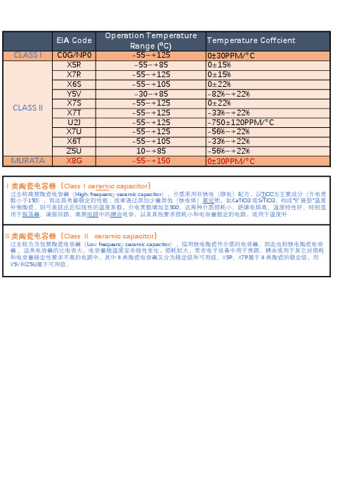
CLASS I C0G/NP0-55~+1250±30PPM/⁰CX5R-55~+850±15%X7R-55~+1250±15%X6S-55~+1050±22%Y5V-30~+85-82%~+22%X7S-55~+1250±22%CLASS IIX7T-55~+125-33%~+22%U2J-55~+125-750±120PPM/⁰CX7U-55~+125-56%~+22%X6T-55~+105-33%~+22%Z5U10~+85-56%~+22%MURATA X8G-55~+1500±30PPM/⁰CⅠ类陶瓷电容器(ClassⅠceramic capacitor)过去称高频陶瓷电容器(High-frequency ceramic capacitor),介质采用非铁电(顺电)配方,以TiO2为主要成分(介电常 数小于150),因此具有最稳定的性能;或者通过添加少量其他(铁电体)氧化物,如CaTiO3 或SrTiO3,构成“扩展型”温度 补偿陶瓷,则可表现出近似线性的温度系数,介电常数增加至500。
这两种介质损耗小、绝缘电阻高、温度特性好。
特别适 用于振荡器、谐振回路、高频电路中的耦合电容,以及其他要求损耗小和电容量稳定的电路,或用于温度补Ⅱ类陶瓷电容器(Class Ⅱ ceramic capacitor)过去称为为低频陶瓷电容器(Low frequency ceramic capacitor),指用铁电陶瓷作介质的电容器,因此也称铁电陶瓷电容 器 。
这类电容器的比电容大,电容量随温度呈非线性变化,损耗较大,常在电子设备中用于旁路、耦合或用于其它对损耗 和电容量稳定性要求不高的电路中。
其中Ⅱ类陶瓷电容器又分为稳定级和可用级。
X5R、X7R属于Ⅱ类陶瓷的稳定级,而Y5V和Z5U属于可用级。
各品牌贴片电容规格资料汇总
各品牌贴片电容规格资料汇总贴片电容是一种常见的电子元器件,被广泛用于电路设计和生产中。
它们具有小巧的尺寸、稳定性好以及较低的成本。
各品牌贴片电容的规格资料是电子行业从业人员日常工作所必需的信息之一、本文将汇总一些知名品牌的贴片电容规格资料,供读者参考。
1. Murata(村田)Murata是一家日本电子元器件制造企业,也是全球最大的陶瓷电容制造商之一、以下为Murata的一些常用贴片电容规格资料:-容量范围:从0.1pF到100μF-额定电压范围:从4V到100V-外观尺寸:包括0201、0402、0603、0805、1206、1210、1808、1812等常见尺寸-允许偏差:±0.1pF到±20%不等-温度系数:X7R、X5R、NPO等不同温度系数可选-特殊系列:如高温型、高电压型、耐震性、防激波等2. Samsung(三星)三星是一家韩国综合电子企业,也是全球最大的半导体制造商之一、以下为三星的一些常用贴片电容规格资料:-容量范围:从0.5pF到22μF-额定电压范围:从4V到100V见尺寸-允许偏差:±0.1pF到±20%不等-温度系数:X7R、X5R、X6S、X8S等不同温度系数可选-特殊系列:如高温型、高电压型、耐震性、防激波等3.TDK(TDK公司)TDK是一家日本电子元器件制造企业,也是全球最大的磁性元件制造商之一、以下为TDK的一些常用贴片电容规格资料:-容量范围:从0.1pF到220μF-额定电压范围:从4V到100V-外观尺寸:包括0201、0402、0603、0805、1206、1210、1812等常见尺寸-允许偏差:±0.1pF到±20%不等-温度系数:X7R、X5R、X6S、X7S等不同温度系数可选-特殊系列:如高温型、高电压型、耐震性、防激波等4. Yageo(圆石)圆石是一家台湾电子元器件制造企业,也是全球最大的无源元件制造商之一、以下为圆石的一些常用贴片电容规格资料:-容量范围:从0.1pF到2.2μF-额定电压范围:从4V到100V见尺寸-允许偏差:±0.1pF到±20%不等-温度系数:X7R、X5R、X6S、X7S等不同温度系数可选-特殊系列:如高温型、高电压型、耐震性、防激波等5.AVX(AECOM公司)AVX是一家美国电子元器件制造企业,也是全球领先的陶瓷电容制造商之一、以下为AVX的一些常用贴片电容规格资料:-容量范围:从0.1pF到47μF-额定电压范围:从6.3V到100V-外观尺寸:包括0201、0402、0603、0805、1206、1210、1808、1812等常见尺寸-允许偏差:±0.1pF到±20%不等-温度系数:X7R、X5R、X6S、X7S等不同温度系数可选-特殊系列:如高温型、高电压型、耐震性、防激波等以上仅为一些知名品牌贴片电容规格资料的简要汇总,实际应用中还需要根据具体的设计要求、电路需求以及可用的供应商和库存情况选择最合适的贴片电容。
三星电容编码识别
三星电容编码识别你看盘子的料号如下对比:CL 03 B 104 K Q 8 N N N C1 2 3 4 5 6 7 8 9 10 111 系列编码:CL=积层陶瓷电容2 尺寸编码03=0201(0603) 21=0805(2012) 42=1808(4520)05=0402(1005) 31=1206(3216) 43=1812(4532)10=0603(1608) 32=1210(3225) 55=2220(5750)14=0504(1410) 01=0306(0816) 12=0508(1220)3 介质I类 II类C=C0G S=S2H L=S2LP=P2H T=T2HR=R2H U=U2JA=X5R F=Y5VB=X7R X=X6S4 容量电容容量用三位数表示,前面两位为有效数字,第三位为有效数字后"O"的位数如:104 = 1 00000 (单位pF)如果中间一位为R 则表示"."如:4R7 = 4.7pF5 电容的误差:B=±0.1pf F=±1pf±1% K=±10%C=±0.25pf G=±2% M=±20%D=±0.5pf? J=±5% Z=+80/-20%6 额定电压R=4V O =16V B =50V E = 250V I = 1000VQ=6.3V A =25V C=100V G = 500V J = 2000VP =10V L =35V D =200V H = 630V K= 3000V7 厚度:3=0.30毫米 A=0.65毫米 M=1.15毫米 I=2.00毫米 Q=1.25毫米5=0.50毫米 C=0.85毫米 F=1.25毫米 J=2.50毫米 V=2.50毫米8=0.80毫米 D=1.00毫米 H=1.60毫米 L=3.20毫米8 内电极A=常规产品钯/银/镍屏蔽/锡 100%N=常规产品镍/铜/镍屏蔽/锡 100%G=常规产品铜/铜/镍屏蔽/锡 100%L=低侧面产品镍/铜/镍屏蔽/锡 100%9 产品编码A =阵列(2-元素) L =LICCB =阵列(4-元素) N =常规P =自动 C=高频10 特殊编码11 包装编码B=散装 O=纸版箱料带,10英寸料盘 E=压花纸版箱,7英寸料盘P=散装箱 D=纸版箱料带,13英寸料盘(10000ea) F=压花纸版箱,13英寸料盘C=纸版箱料带,7英寸料盘 L=纸版箱料带,13英寸料盘(15,000ea) S=压花纸版箱,10英寸料盘如有侵权请联系告知删除,感谢你们的配合!。
电容参数:X5R,X7R,Y5V,COG详解

电容参数:X5R,X7R,Y5V,COG详解我们选择⽆极性电容式,不知道⼤家是否有注意到电容的X5R,X7R,Y5V,COG等等看上去很奇怪的参数,有些摸不着头脑,本⼈特意为此查阅了相关的⽂献,现在翻译出来奉献给⼤家。
这类参数描述了电容采⽤的电介质材料类别,温度特性以及误差等参数,不同的值也对应着⼀定的电容容量的范围。
具体来说,就是:X7R常⽤于容量为3300pF~0.33uF的电容,这类电容适⽤于滤波,耦合等场合,电介质常数⽐较⼤,当温度从0°C变化为70°C时,电容容量的变化为±15%;Y5P与Y5V常⽤于容量为150pF~2nF的电容,温度范围⽐较宽,随着温度变化,电容容量变化范围为±10%或者+22%/-82%。
对于其他的编码与温度特性的关系,⼤家可以参考表4-1。
例如,X5R的意思就是该电容的正常⼯作温度为-55°C~+85°C,对应的电容容量变化为±15%。
表4-1 电容的温度与容量误差编码下⾯我们仅就常⽤的NPO、X7R、Z5U和Y5V来介绍⼀下它们的性能和应⽤以及采购中应注意的订货事项以引起⼤家的注意。
不同的公司对于上述不同性能的电容器可能有不同的命名⽅法,这⾥我们引⽤的是AVX公司的命名⽅法,其他公司的产品请参照该公司的产品⼿册。
NPO、X7R、Z5U和Y5V的主要区别是它们的填充介质不同。
在相同的体积下由于填充介质不同所组成的电容器的容量就不同,随之带来的电容器的介质损耗、容量稳定性等也就不同。
所以在使⽤电容器时应根据电容器在电路中作⽤不同来选⽤不同的电容器。
⼀ NPO电容器NPO是⼀种最常⽤的具有温度补偿特性的单⽚陶瓷电容器。
它的填充介质是由铷、钐和⼀些其它稀有氧化物组成的。
NPO电容器是电容量和介质损耗最稳定的电容器之⼀。
在温度从-55℃到+125℃时容量变化为0±30ppm/℃,电容量随频率的变化⼩于±0.3ΔC。
三星规格书(中文版)
ƚƚƚ
7.电容厚度编码:
3 = 0.30 עA = 0.65 עM = 1.15ע 5 = 0.50 עC = 0.85 עF = 1.25ע 8 = 0.80 עD = 1.00 עH = 1.60ע
I = 2.00ע J = 2.50ע L= 3.20ע
July 2006
MUTLAYER CERAMIC CAPACITORS
The specification and designs contained herein may be subject to change without notice.
QS 9000/ISO 9001
Registered by BSI to QS 9000 or ISO 9001 under BSI’s accreditation by UKAS for Certification. Registration NO : FM25309(2002. 2. 28)
6.Low ESL Capacitors
Packaging Specification
67
Reliability Test Condition
71
1.Appearance
2.Insulation Resistance
3.Withstanding Voltage
4.Capacitance
5.Q Factor / Tan Ҝ
Q = 1.25*ע V = 2.50*ע
8.电容内电极 / 端子 / 电镀编码:
A=常规产品 钯/银/镍屏蔽/锡 100% N=常规产品 镍/铜/镍屏蔽/锡 100% G=常规产品 铜/铜/镍屏蔽/锡 100% L=低侧面产品 镍/铜/镍屏蔽/锡 100%
- 1、下载文档前请自行甄别文档内容的完整性,平台不提供额外的编辑、内容补充、找答案等附加服务。
- 2、"仅部分预览"的文档,不可在线预览部分如存在完整性等问题,可反馈申请退款(可完整预览的文档不适用该条件!)。
- 3、如文档侵犯您的权益,请联系客服反馈,我们会尽快为您处理(人工客服工作时间:9:00-18:30)。
Page 1 of 10Issued Date :2014. 01. 14Test Report No. F690101/LF-CTSAYAA14-01202SAMSUNG ELECTRO-MECHANICS CO., LTD.314Maetan-dong,Yeoungtong-gu Suwon-si,Gyeonggi-do KoreaThe following sample(s) was/were submitted and identified by/on behalf of the client as:-SGS File No.:AYAA14-01202Product Name : MLCC A(X5R) TYPE_MLCC X (X6S) TYPE_MLCC J(JIS-B)TYPE Item No./Part No.:N/AClient Reference Data : CLxxAxxxxxxxxxx,CLxxXxxxxxxxxxx,CLxxJxxxxxxxxxx 2014. 01. 072014. 01. 14to 2014. 01. 08Test Period :Received Date :Test Comments :By the applicant's specific request, the sampling and testing was performed only for the part indicated in the photo without disassembly.By the applicant’s request, item No.s/part No.s & client reference information are stated/added on report.Report Comments:For further details, please refer to following page(s)Test Results:Jeff Jang / Chemical Lab MgrSGS Korea Co., Ltd.The results shown in this test report refer only to the sample(s) submitted by the client, not cover the quality of the whole batch. This reportshould be used as intended, and shall not be used for advertisement and lawsuit.This document is issued by the Company subject to its General Conditions of Service printed overleaf, available on request or accessible at </en/Terms-and-Conditions.aspx> and, for electronic format documents, subject to Terms and Conditions for Electronic Documents at /terms_e-document.htm </terms_e-document.htm>. Attention is drawn to the limitation of liability, indemnification andPage 2 of 10Issued Date :2014. 01. 14Test Report No. F690101/LF-CTSAYAA14-01202Sample No. :AYAA14-01202.001MLCC A(X5R) TYPE_MLCC X (X6S) TYPE_MLCC J(JIS-B)TYPE Sample Description :Item No./Part No.:N/A N/AMaterials :Flame Retardants-PBBs/PBDEsResultsMDLTest MethodUnitTest Items5With reference to IEC 62321:2008, GC-MS Monobromobiphenyl N.D.mg/kg 5With reference to IEC 62321:2008, GC-MS Dibromobiphenyl N.D.mg/kg 5With reference to IEC 62321:2008, GC-MS Tribromobiphenyl N.D.mg/kg 5With reference to IEC 62321:2008, GC-MS Tetrabromobiphenyl N.D.mg/kg 5With reference to IEC 62321:2008, GC-MS Pentabromobiphenyl N.D.mg/kg 5With reference to IEC 62321:2008, GC-MS Hexabromobiphenyl N.D.mg/kg 5With reference to IEC 62321:2008, GC-MS Heptabromobiphenyl N.D.mg/kg 5With reference to IEC 62321:2008, GC-MS Octabromobiphenyl N.D.mg/kg 5With reference to IEC 62321:2008, GC-MS Nonabromobiphenyl N.D.mg/kg 5With reference to IEC 62321:2008, GC-MS Decabromobiphenyl N.D.mg/kg 5With reference to IEC 62321:2008, GC-MS Monobromodiphenyl ether N.D.mg/kg 5With reference to IEC 62321:2008, GC-MS Dibromodiphenyl ether N.D.mg/kg 5With reference to IEC 62321:2008, GC-MS Tribromodiphenyl ether N.D.mg/kg 5With reference to IEC 62321:2008, GC-MS Tetrabromodiphenyl ether N.D.mg/kg 5With reference to IEC 62321:2008, GC-MS Pentabromodiphenyl ether N.D.mg/kg 5With reference to IEC 62321:2008, GC-MS Hexabromodiphenyl ether N.D.mg/kg 5With reference to IEC 62321:2008, GC-MS Heptabromodiphenyl ether N.D.mg/kg 5With reference to IEC 62321:2008, GC-MS Octabromodiphenyl ether N.D.mg/kg 5With reference to IEC 62321:2008, GC-MS Nonabromodiphenyl ether N.D.mg/kg 5With reference to IEC 62321:2008, GC-MSDecabromodiphenyl etherN.D.mg/kgThis document is issued by the Company subject to its General Conditions of Service printed overleaf, available on request or accessible at </en/Terms-and-Conditions.aspx> and, for electronic format documents, subject to Terms and Conditions for Electronic Documents at /terms_e-document.htm </terms_e-document.htm>. Attention is drawn to the limitation of liability, indemnification andPage 3 of 10Issued Date :2014. 01. 14Test Report No. F690101/LF-CTSAYAA14-01202Sample No. :AYAA14-01202.001MLCC A(X5R) TYPE_MLCC X (X6S) TYPE_MLCC J(JIS-B)TYPE Sample Description :Item No./Part No.:N/A N/AMaterials :Flame RetardantsResultsMDLTest MethodUnitTest Items5USEPA 3540C, LC/MS Hexabromocyclododecane (HBCDD)N.D.mg/kg Other(s)ResultsMDLTest MethodUnitTest Items1US EPA 3540C/3550C, LC/MS PFOA (Perfluorooctanoic acid)N.D.mg/kg 1US EPA 3540C/3550C, LC/MSPFOS (PerfluorooctaneSulfonates-Acid/Metal Salt/Amide)N.D.mg/kg(1) N.D. = Not detected.(<MDL)(2) mg/kg = ppm(3) MDL = Method Detection Limit (4) - = No regulation(5) Negative = Undetectable / Positive = Detectable (6) ** = Qualitative analysis (No Unit)(7) * = Boiling-water-extraction:Negative = Absence of CrVI coatingPositive = Presence of CrVI coating; the detected concentration in boiling-water-extraction solution is equal or greater than 0.02 mg/kg with 50 cm2 sample surface area.NOTE:This document is issued by the Company subject to its General Conditions of Service printed overleaf, available on request or accessible at </en/Terms-and-Conditions.aspx> and, for electronic format documents, subject to Terms and Conditions for Electronic Documents at /terms_e-document.htm </terms_e-document.htm>. Attention is drawn to the limitation of liability, indemnification andTest Report No. F690101/LF-CTSAYAA14-01202Page 4 of 10Issued Date :2014. 01. 14Picture of Sample as Received:This document is issued by the Company subject to its General Conditions of Service printed overleaf, available on request or accessible at </en/Terms-and-Conditions.aspx>and, for electronic format documents, subject to Terms and Conditions for Electronic Documents at /terms_e-document.htm </terms_e-document.htm>. Attention is drawn to the limitation of liability, indemnification andPage 5 of 10Issued Date :2014. 01. 14Test Report No. F690101/LF-CTSAYAA14-01202Testing Flow Chart for RoHS:Cd/Pb/Hg/Cr 6+/PBBs&PBDEs TestingSample MeasurementDATAGC/MSSolvent Extraction of the SampleScreen AnalysisConcentration/Dilution of Extraction SolutionFiltrationCd/Pb/HgPBBs/PBDEsMechanic_SampleSample MeasurementAcid Digestion with Microwave/HotplateFiltrationResidueTotal DigestionICP-AES/AAS/MSDATAMechanic_SampleConfirm with UV-VisCrSample MeasurementAdding Extraction SolutionMetallic MaterialUV-VisDATAMechanic_Sample 6+Filtration and pH AdjustmentAdding 1,5-Diphenylcarbazidefor Color DevelopmentHeating to 90~95°C for ExtractionNonmetallic MaterialAdding 1,5-Diphenylcarbazide for Color DevelopmentMechanic_SampleSample MeasurementSpot Test / Boiling Water Extraction DATACr6+The samples were dissolved totally by pre-conditioning method according to above flow chart for Cd,Pb,Hg. Section Chief : Gilsae YiThis document is issued by the Company subject to its General Conditions of Service printed overleaf, available on request or accessible at </en/Terms-and-Conditions.aspx> and, for electronic format documents, subject to Terms and Conditions for Electronic Documents at /terms_e-document.htm </terms_e-document.htm>. Attention is drawn to the limitation of liability, indemnification andPage 6 of 10Issued Date :2014. 01. 14Test Report No. F690101/LF-CTSAYAA14-01202Inorganic ElementsFlow Chart for Inorganic Elements TestingAcid Digestion with Microwave/HotplateSample MeasurementMechanic_SampleDATAICP-AESTotal DigestionResidueFiltrationAntimony(Sb) , Beryllium(Be) , Phosphorus(P) , Arsenic(As) etc.Major Inorganic Heavy MetalsThis document is issued by the Company subject to its General Conditions of Service printed overleaf, available on request or accessible at </en/Terms-and-Conditions.aspx> and, for electronic format documents, subject to Terms and Conditions for Electronic Documents at /terms_e-document.htm </terms_e-document.htm>. Attention is drawn to the limitation of liability, indemnification andPage 7 of 10Issued Date :2014. 01. 14Test Report No. F690101/LF-CTSAYAA14-01202Flow Chart for Halogen TestWeigh the samples into the combustion boat.Analyze absorbed solution using Ion Chromatography.Admit O 2 gas or O 2 +Ar 2 gas and start the combustion.Add absorption solution into the bomb or tube.Sample screening using XRF.Liquid containing water(>80%)?Dilute the solution (EPA300)NoYesAllow during absorption of the burnt gas.DataThis document is issued by the Company subject to its General Conditions of Service printed overleaf, available on request or accessible at </en/Terms-and-Conditions.aspx> and, for electronic format documents, subject to Terms and Conditions for Electronic Documents at /terms_e-document.htm </terms_e-document.htm>. Attention is drawn to the limitation of liability, indemnification andTest Report No. F690101/LF-CTSAYAA14-01202Issued Date :2014. 01. 14Page 8 of 10Flow Chart for Phthalate TestSample pretreatment / SeparationSample extraction by soxhlet methodConcentrate/Dilute Extracted solutionAnalysis was performed by GC/MSQA / QC review / Check analysis resultDataThis document is issued by the Company subject to its General Conditions of Service printed overleaf, available on request or accessible at </en/Terms-and-Conditions.aspx>and, for electronic format documents, subject to Terms and Conditions for Electronic Documents at /terms_e-document.htm </terms_e-document.htm>. Attention is drawn to the limitation of liability, indemnification andTest Report No. F690101/LF-CTSAYAA14-01202Issued Date :2014. 01. 14Page 9 of 10Flow Chart for PFOS/PFOA TestSample pretreatment / SeparationSample extractionConcentrate/Dilute Extracted solutionAnalysis was performed by HPLC/MSQA / QC review / Check analysis resultDataThis document is issued by the Company subject to its General Conditions of Service printed overleaf, available on request or accessible at </en/Terms-and-Conditions.aspx>and, for electronic format documents, subject to Terms and Conditions for Electronic Documents at /terms_e-document.htm </terms_e-document.htm>. Attention is drawn to the limitation of liability, indemnification andTest Report No. F690101/LF-CTSAYAA14-01202Issued Date :2014. 01. 14Page 10 of 10Testing Flow Chart for HBCDSample pretreatmentSample extraction by organic solventConcentrate/Dilute Extracted solutionLC/MS analysisDATA*** End of Report ***This document is issued by the Company subject to its General Conditions of Service printed overleaf, available on request or accessible at </en/Terms-and-Conditions.aspx>and, for electronic format documents, subject to Terms and Conditions for Electronic Documents at /terms_e-document.htm </terms_e-document.htm>. Attention is drawn to the limitation of liability, indemnification and。