
2011年,中国镍产量约为44.6万吨,其中电解镍、镍铁占比分别为41.5%和56.5%--北京水清木华研究中心
2011-2012年全球及中国镍行业研究报告2011年,受英美资源Barro Alto镍项目、淡水河谷Onça Puma 镍项目等建成投产,以及中国含镍生铁产量快速增加等因素影响,全球镍产量同比增长10.0%,至100%158.9万吨;消费量同比增长6.9%,至157.2万吨。
2012年,世界各地镍项目的陆续投产以及新增产能的释放,将使镍供应过剩的压力进一步加大,预计全年镍过剩5.0万吨。
与全球镍供需格局不同,中国镍市一直处于供不应求的局面。
2011年中国不锈钢产量同比增长11.9%,极大地刺激了镍的消费,全年镍消费量同比增长17.1%,远高增极大刺激镍消费年镍消费增高于同期世界镍消费增速。
与此同时,中国镍产量也在大幅提升,其中增长最快的是镍铁。
2010年,中国镍产量为32.6万吨,其中镍铁产量(含镍量)为16.1万吨,首次超过电解镍产量,成为中国产量最大的镍产品。
2011年,中国镍产量约为44.6万吨,其中电解镍、镍铁占比分别为41.5%和56.5%。
近年,中国镍铁市场飞速发展的主要原因有两点,一是不锈钢厂商对镍铁的使用比例不断提高,有的甚至达到50%以上。
二是镍铁冶炼工艺的进步。
目前先进且环保的回转窑—电炉(RKEF)工艺已经被镍铁行业接受,并成为主流。
在中国,镍铁生产所需的红土镍矿几乎全部依赖进口,2011年中国累计从印度尼西亚、菲律宾、澳大利亚等国进口镍矿砂及精矿4805.6万吨,同比增长92.4%,其中红土镍矿占比超过98%。
2012年,印尼正式宣布,从5月6日起48056924%对镍等14种原矿征收20%的出口税。
这一禁令的实施将使2012年中国红土镍矿的供应趋于紧张;同时助推镍价的上涨。
镍铁作为金属镍的替代产品,其价格难以摆脱LME镍价的控制。
2011年,LME镍价大幅下挫,随之国内镍价震荡下滑。
高、中镍铁也出现了不同程度的降价,而低镍铁由于受200系不锈钢需求增加的影响,价格不降反增。
《2011-2012年全球及中国镍行业研究报告》除了研究全球及中国镍市供需状况,镍价走势,镍铁市场外,还着重研究了Norilsk Nickel、Sale SA 等四家国际龙头企业,以及金川集团、吉恩镍业、新鑫矿业等7家中国重点生产商。
金川集团是中国最大的镍生产商,2011年镍产量为13.0万吨,位居全球第三。
吉恩镍业是中国第二大镍生产商,也是中国最大的镍盐生产商,公司主要产品为电解镍和硫酸镍,2011年这两大产品营业收入共占到公司总收入的62.85%。
新鑫矿业拥有丰富的镍矿资源,2011年旗下矿山镍金属量达到57.26万吨,全年生产电解镍8128吨,占到中国电解报告目录3.3.1 国内价格332第一章镍概述1.1 定义12 3.3.2 进口价格本章小结1.2 镍矿资源1.3 镍的冶炼第四章中国镍市场供需分析4.1 生产情况4.1.1 产量412第二章全球镍市场供需分析2.1 供应情况2.2 消费情况 4.1.2 产量构成4.2 消费情况4.2.1 消费量2.2.1 消费量2.2.2 消费结构本章小结4.2.2 消费结构4.2.3 不锈钢市场4.3 进出口分析第三章中国镍矿资源现状3.1 镍矿储量及分布4.3.1 进口4.3.2 出口5.2 中国镍价7.2.1 企业简介7.2.2 经营情况第六章中国镍铁市场分析6.1 镍铁概述6.2 供需现状7.2.3 在华发展7.3 BHP Billiton 7.3.1企业简介6.2.1 供应情况6.2.2 需求情况6.3 进出口现状7.3.2 经营情况7.3.3 在华发展7.4 Xstrata Plc 6.4 价格走势6.5镍铁行业面临的问题本章小结7.4.1 企业简介7.4.2 经营情况7.4.3 在华发展第七章国际镍重点企业研究7.1Norilsk Nickel 本章小结7.1 Norilsk Nickel 7.1.1 企业简介7.1.2 经营情况713第八章中国镍行业重点企业研究8.1 金川集团8.1.1 企业简介812.1.3 在华发展7.2 Vale SA8.1.2经营情况8.1.3 研发与投资8.2吉恩镍业8.2.1 企业简介8.5.3 研发与投资8.6广西银亿科技矿冶有限公司8.2.2 经营情况8.2.3 营收构成8.2.4 毛利率8.6.1 企业简介8.6.2 经营情况8.7陕西华泽镍钴金属有限公司8.2.5 投资分析8.3新鑫矿业8.3.1 企业简介8.7.1 企业简介8.7.2 经营情况本章小结8.3.2 经营情况8.3.3 毛利率8.3.4 镍矿开发进展8.4 中国镍资源8.4.1 企业简介8.4.28.4.2经营情况8.4.3 研发与投资8.5江西江锂科技有限公司851.5.1企业简介8.5.2经营情况图表目录•图:2000-2010年全球镍储量•表:2010年全球主要国家镍储量•表:2008年全球镍资源(分产品)分布•图:2004-2012年全球镍产量•表:2011年全球镍产量前十企业•图:20042012年全球镍消费量2004-2012•图:2007-2012年全球不锈钢粗钢产量及同比增长•图:2011年全球不锈钢粗钢(分产品)产量构成•图:2011年全球镍消费结构•表:2009-2012年全球镍供需平衡分析•图:中国镍矿资源主要类型及占比•图:中国镍矿储量(分省市)分布图中国镍矿储量(分省市)分布•图:2007-2012年中国镍矿砂及精矿进口量•表:2010-2011年中国镍矿砂及精矿(分国家)进口量及进口金额表:2011年中国镍矿砂及精矿进口额前10个省市表•图:2011年中国镍矿港口库存量•表:近年中国在东南亚投资的镍冶炼厂项目•图:2009-2012年中国红土镍矿价格走势•图:2009-2012年中国镍矿砂及精矿进口价格•图:2005-2011年中国镍产量•图:2007-2011年中国镍产量结构•图:2005-2011年中国镍消费量•图:2004-2010年中国镍消费结构•表:中国不锈钢冶炼用含镍原料的优劣势比较•图:2007-2012年中国不锈钢粗钢产量及同比增长•表:2011年中国不锈钢粗钢(分产品)产量及增速•图:2011-2012年中国300系列不锈钢卷板价格•图:2007-2012年中国精炼镍进口量•表:2009-2011年中国精炼镍(分国家/地区)进口量•表:2011年中国系列镍产品出口税率•图:2007-2012年中国精炼镍及合金出口量•表:2009-2012年中国精炼镍及合金(分国家/地区)出口量图:20112012年LME镍库存及现货价格•2011-2012•图:2011-2012年长江镍现货价格•图:中国红土镍矿分品位冶炼方法及镍铁产品分类•图:2007-2011年中国镍铁产量(含镍量)•图:2011年中国主要新建镍铁项目•图:2011年中国不锈钢(分产品)产量构成•表:2009-2012年中国镍铁进出口情况•表:2011年中国镍铁进口(分来源国)构成•表:2011年中国镍铁出口(分目的地)构成•图:2011-2012年中国镍铁价格走势•图:2011年中国高炉镍铁和电炉镍铁生产成本结构•表:Norilsk Nickel 矿山资源及储量•表:2005-2011年Norilsk Nickel 主要金属产量•图:2006-2010年Norilsk Nickel 总收入及毛利润•表:2009-2011年Norilsk Nicke主要产品收入图:20072011年Vale公司营业收入和净利润•2007-2011•表:2009-2011年Vale公司营业收入(分产品)构成•图:Vale镍生产子公司及分布表:20092011年Vale公司镍矿运营情况•2009-2011•表:2008-2011年Vale公司镍产量•图:2011年Vale公司镍销售额(分区域)构成•表:2011财年BHP Billiton (分产品)产量及同比增长•表:2010-2011财年BHP Billiton (分区域)镍产、销量•图:2006-2011年Xstrata plc收入及营业利润•表:2010-2011年Xstrata plc主要产品收入及同比增长•图:2009-2011年Xstrata plc 镍收入及营业利润•表:2009-2011年Xstrata plc 镍产量•表:2009-2011年Xstrata plc 镍销量•表:2011年全球TOP5企业镍产量及占比•表:金川集团基本情况•图:2007-2012年金川集团营业收入和利润总额•表:2007-2012年金川集团主要产品产量•表:吉恩镍业基本情况图:20082012年吉恩镍业主营业务收入和净利润•2008-2012•表:2010-2011年吉恩镍业主要产品收入及占比•表:2009-2011年吉恩镍业(分产品)毛利率•表:2011年吉恩镍业国内镍资源及储量•表:2011年吉恩镍业国外镍资源及储量•表:新鑫矿业基本情况•图:2007-2011年新鑫矿业营业收入和净利润•图:2006-2012年新鑫矿业电解镍产量•表:2009-2011年新鑫矿业(分产品)营业收入•图:2006-2011年新鑫矿业毛利率•表:2011年新鑫矿业镍资源量•表:2011年新鑫矿业镍储量•表:2009-2011年新鑫矿业镍矿冶炼能力•表:新鑫矿业基本情况•图:2006-2011年中国镍资源收入及净利润•表:江锂科技基本情况•表:银亿科技基本情况•表:华泽镍钴基本情况。
SSD540U失步解列说明书V1.00
版本声明
本说明书适用于基本型的 SSD 540U 失步解列装置。如基本型的 SSD 540U 装置无法满足需求以随装置 提供的工程说明为准,本说明书仅供参考。 本说明书包含技术内容介绍、使用说明和现场验收说明。 本说明书适用于 SSD 540U 失步解列装置 V1.00 版本保护软件。
产品说明书版本修改记录表
国 电 南 自 Q/GDNZ.J.01.86-2008 标准备案号:148-2008
SSD 540U 失步解列装置 说 明 书
国电南京自动化股份有限公司
GUODIAN NANJING AUTOMATION CO.,LTD
SSD 540U 失步解列装置 说明书
V 1.00
国电南京自动化股份有限公司 2011 年 7 月
10 9 8 7 6 5 4 3 2 1 序号 V1.00 说明书版本号 修 第一版 改 摘 要 2011.7 修改日期
*
业务联系及服务
电话:(025)51183776 传真: (025)51183776
* * *
本说明书可能会被修改,请注意核对实际产品与说明书的版本是否相符,本公司根据用户需求采用最
目
安全声明 版本声明
录
1.装置简介 ........................................................................................................................................................................ 1 1.1 主要用途.................................................................................................................................................................. 1 1.2 基本功能及技术特点 ............................................................................................................................................. 1 2.技术参数 ........................................................................................................................................................................ 3 2.1 2.2 2.3 2.4 2.5 2.6 2.7 额定电气参数 ......................................................................................................................................................... 3 主要技术指标 ......................................................................................................................................................... 3 环境条件 ................................................................................................................................................................. 4 绝缘性能 ................................................................................................................................................................. 4 耐湿热性能 ............................................................................................................................................................. 4 电磁兼容性 ............................................................................................................................................................. 4 机械性能 ................................................................................................................................................................. 5
EN50525-2-41-2011
Kabel und Leitungen Starkstromleitungen mit Nennspannungen bis 450/750 V (U0/U) Teil 2-41: Starkstromleitungen für allgemeine Anwendungen Einadrige Leitungen mit vernetzter SilikonIsolierung
The following dates were fixed:
– latest date by which the EN has to be implemented at national level by publication of an identical national standard or by endorsement
4.1 Non-sheathed cables for fixed wiring – H05S-U and H05S-K................................... 5 4.2 Non-sheathed cables for internal wiring – H03S-K .................................................. 5 4.3 Braided cables for fixed wiring – H05SJ-U and H05SJ-K ......................................... 6 4.4 Sheathed cables for fixed wiring – H05SS-K ........................................................... 6 Annex A (normative) Tests for cables to EN 50525-2-41........................................................ 8 Annex B (normative) General data......................................................................................... 9 Annex C (normative) Requirements for compatibility test ..................................................... 11 C.1 Test conditions ..................................................................................................... 11 C.2 Requirements ....................................................................................................... 11 Bibliography ......................................................................................................................... 12
VU和db是两种音量单位

VU和db是两种音量单位,0VU相当于-3dB,vu是对音量进行了加权处理,它的值比较接近人耳的听感,而db就比较精确。
0UV=4dB.我们的播控都用0UV做为标准,而演播室以0DB作为标准,有点乱。
另外关于音量有效值电平指示的响应也不同,有的设备已经过了,但有的设备还在0UV以下。
估计也是由于厂方有不同的标准的缘故。
VU表反映的是信号的平均值,这种表对声音信号电平的骤变反映比较迟钝。
PPM表是峰值节目表,它能快速扑捉到信号包络的变化,但它有指示值下降时间的设置,为了便于观察。
基本换算公式:0VU=+4dBu=-8PPU (在1KHz稳态信号下)dB是个相对度量单位,如果没有0d B的基准说明,dB值表达的意义是不确定的。
当然,由于有明确的定义,dBu、dBm、dBV这些单位都是有绝对的值所对应的。
VU作为一个平均值度量单位,总之接近人耳的听觉响应特点,符合人耳“确切“的听觉响应。
一般情况下,VU与dBu的对应关系为0VU=+4dBu,但0VU是否为一个绝对值,我一直存有疑问,我觉得0VU更可能也是一个相对值(这一点未经权威资料证实,提出来供商榷),理由如下:1、VU表刻度是不均匀的,如0VU为绝对值,则过大、过小音频信号很难在面板上精确表现出来,而各传输环节的音量大小往往不太一致,我所知道的一个电台光纤发送端0V U就设为+2dBu。
2、我单位使用的Logit ekVU表使用说明书中便指出,该设备在出厂时0VU设定在+4dBu,隐含这个值可重新加以设定的意思。
数字音频设备的满度电平本标准规定了广播电视数字音频系统中,节目制作、播出及传输系统数字设备的满度电平值。
本标准适用于广播电视数字音频系统,其他数字音频系统可参照执行。
TPS54620 Step-Down Converter Evaluation Module Use
User’s GuideTPS54620 Step-Down Converter Evaluation Module User's GuideABSTRACTThis user’s guide contains background information for the TPS54620 as well as support documentation forthe TPS54620EVM-374 evaluation module (HPA374). Also included are the performance specifications, the schematic, and the bill of materials for the TPS54620EVM-374.Table of Contents1 Introduction (2)2 Test Setup and Results (5)3 Board Layout (12)4 Schematic and Bill of Materials (18)5 Revision History (19)List of FiguresFigure 2-1. TPS54620EVM-374 Efficiency (6)Figure 2-2. TPS54620EVM-374 Low Current Efficiency (6)Figure 2-3. TPS54620EVM-374 Load Regulation (7)Figure 2-4. TPS54620EVM-374 Line Regulation (7)Figure 2-5. TPS54620EVM-374 Transient Response (8)Figure 2-6. TPS54620EVM-374 Loop Response (8)Figure 2-7. TPS54620EVM-374 Output Ripple (9)Figure 2-8. TPS54620EVM-374 Input Ripple (9)Figure 2-9. TPS54620EVM-374 Start-Up Relative to V IN (10)Figure 2-10. TPS54620EVM-374 Start-up Relative to Enable (10)Figure 2-11. TPS54620EVM-374 Thermal Image (11)Figure 3-1. TPS54620EVM-374 Top-Side Layout (13)Figure 3-2. TPS54620EVM-374 Layout 2 (14)Figure 3-3. TPS54620EVM-374 Layout 3 (15)Figure 3-4. TPS54620EVM-374 Bottom-Side layout (16)Figure 3-5. TPS54620EVM-374 Top-Side Assembly (17)Figure 4-1. TPS54620EVM-374 Schematic (18)List of TablesTable 1-1. Input Voltage and Output Current Summary (2)Table 1-2. TPS54620EVM-374 Performance Specification Summary (2)Table 1-3. Output Voltages Available (3)Table 2-1. EVM Connectors and Test Points (5)Table 4-1. TPS54620EVM-374 Bill of Materials (19)TrademarksAll trademarks are the property of their respective owners.Introduction 1 Introduction1.1 BackgroundThe TPS54620 dc/dc converter is designed to provide up to a 6 A output. The TPS54620 implements asplit input power rails with separate input voltage inputs for the power stage and control circuitry. The power stage input (PVIN) is rated for 1.6 V to 17 V while the control input (VIN) is rated for 4.5 to 17 V. TheTPS54620EVM-374 provides both inputs but is designed and tested using the PVIN connected to VIN. Rated input voltage and output current range for the evaluation module are given in Table 1-1. This evaluation module is designed to demonstrate the small printed-circuit-board areas that may be achieved when designing with the TPS54620 regulator. The switching frequency is externally set at a nominal480 kHz. The high-side and low-side MOSFETs are incorporated inside the TPS54620 package along with the gate drive circuitry. The low drain-to-source on resistance of the MOSFET allows the TPS54620 to achievehigh efficiencies and helps keep the junction temperature low at high output currents. The compensation components are external to the integrated circuit (IC), and an external divider allows for an adjustable output voltage. Additionally, the TPS54620 provides adjustable slow start, tracking and undervoltage lockout inputs. The absolute maximum input voltage is 20 V for the TPS54620EVM-374.1.2 Performance Specification SummaryA summary of the TPS54620EVM-374 performance specifications is provided in Table 1-2. Specifications are given for an input voltage of V IN = 12 V and an output voltage of 3.3 V, unless otherwise specified. TheTPS54620EVM-374 is designed and tested for V IN = 8 V to 17 V with the VIN and PVIN pins connect together with the J3 jumper. The ambient temperature is 25°C for all measurements, unless otherwise noted.1.3 ModificationsThese evaluation modules are designed to provide access to the features of the TPS54620. Some modifications can be made to this module.2TPS54620 Step-Down Converter Evaluation Module User's Guide SLVU281B – MAY 2009 – REVISED AUGUST 20211.3.1 Output Voltage Set PointThe output voltage is set by the resistor divider network of R8 and R9. R9 is fixed at 10 kΩ. To change the output voltage of the EVM, it is necessary to change the value of resistor R8. Changing the value of R8 can change the output voltage above 0.8 V. The value of R8 for a specific output voltage can be calculated using Equation 1.)OUT k V -V R V10W(0.88=0.8(1)Table 1-3 lists the R8 values for some common output voltages. Note that V IN must be in a range so that the minimum on-time is greater than 120 ns, and the maximum duty cycle is less than 95%. The values given in Table 1-3 are standard values, not the exact value calculated using Equation 1.1.3.2 Slow Start TimeThe slow start time can be adjusted by changing the value of C7. Use Equation 2 to calculate the required value of C7 for a desired slow start timeTss(ms)Iss(μA)C7(nF)=Vref(V)´(2)The EVM is set for a slow start time of 4 msec using C7 = 0.01 µF.1.3.3 Track InThe TPS54620 can track an external voltage during start up. The J5 connector is provided to allow connection to that external voltage. Ratio-metric or simultaneous tracking can be implemented using resistor divider R5 and R6. See the TPS54620 data sheet (SLVS949) for details.1.3.4 Adjustable UVLOThe under voltage lock out (UVLO) ca be adjusted externally using R1 and R2. The EVM is st for a start voltage of 6.521 V and a stop voltage of 6.065 V using R1 = 35.7 kΩ and R2 = 8.06 kΩ. Use Equation 3 and Equation 4 to calculate required resistor values for different start and stop voltages.ENFALLING START STOPENRISING ENFALLING p h ENRISING V V -V V R1=V I 1-+I V æöç÷èøæöç÷èø(3)ENFALLINGSTOP ENFALLING p h R1×V R2=V -V +R1(I +I )(4) IntroductionIntroduction 1.3.5 Input Voltage RailsThe EVM is designed to accommodate different input voltage levels for the power stage and control logic. During normal operation, the PVIN and VIN inputs are connected together using a jumper across J3. The single input voltage is supplied at J1. If desired, these to input voltage rails may be separated by removing the jumper across J3. Two input voltages must then be provided at both J1 and J2. Test Setup and Results2 Test Setup and ResultsThis section describes how to properly connect, set up, and use the TPS54620EVM-374 evaluation module.The section also includes test results typical for the evaluation module and covers efficiency, output voltage regulation, load transients, loop response, output ripple, input ripple, and start-up.2.1 Input / Output ConnectionsThe TPS54620EVM-374 is provided with input/output connectors and test points as shown in Table 2-1. A power supply capable of supplying 4 A must be connected to J1 through a pair of 20 AWG wires. The jumper acrossJ3 must be in place. See Section 1.3.5 for split input voltage rail operation. The load must be connected toJ7 through a pair of 20 AWG wires. The maximum load current capability must be 6 A. Wire lengths must be minimized to reduce losses in the wires. Test-point TP1 provides a place to monitor the V IN input voltages with TP2 providing a convenient ground reference. TP8 is used to monitor the output voltage with TP9 as the ground reference.Test Setup and Results 2.2 EfficiencyThe efficiency of this EVM peaks at a load current of about 2 A and then decreases as the load current increasesshows the efficiency for the TPS54620EVM-374 at an ambient temperature of 25°C.towards full load. Figure 2-1Figure 2-2 shows the efficiency for the TPS54620EVM-374 at lower output currents below 0.10 A at an ambienttemperature of 25°C.The efficiency may be lower at higher ambient temperatures, due to temperature variation in the drain-to-source resistance of the internal MOSFET. Test Setup and Results 2.3 Output Voltage Load Regulationshows the load regulation for the TPS54620EVM-374.Figure 2-3Measurements are given for an ambient temperature of 25°C.2.4 Output Voltage Line RegulationFigure 2-4shows the line regulation for the TPS54620EVM-374.2.5 Load TransientsFigure 2-5 shows the TPS54620EVM-374 response to load transients. The current step is from 25% to 75% of maximum rated load at 12 V input. Total peak-to-peak voltage variation is as shown, including ripple and noiseon the output.Figure 2-5. TPS54620EVM-374 Transient Response2.6 Loop CharacteristicsFigure 2-6 shows the TPS54620EVM-374 loop-response characteristics. Gain and phase plots are shown for V INFigure 2-6. TPS54620EVM-374 Loop ResponseTest Setup and Results 2.7 Output Voltage RippleFigure 2-7 shows the TPS54620EVM-374 output voltage ripple. The output current is the rated full load of 6 A and V IN= 12 V. The ripple voltage is measured directly across the output capacitors.Figure 2-7. TPS54620EVM-374 Output Ripple2.8 Input Voltage RippleFigure 2-8 shows the TPS54620EVM-374 input voltage. The output current is the rated full load of 4 A and V IN =12 V. The ripple voltage is measured directly across the input capacitors.Figure 2-8. TPS54620EVM-374 Input Ripple Test Setup and ResultsTest Setup and Results 2.9 Powering UpFigure 2-9 and Figure 2-10 show the start-up waveforms for the TPS54620EVM-374 . In Figure 2-9, the output voltage ramps up as soon as the input voltage reaches the UVLO threshold as set by the R1 and R2 resistor divider network. In Figure 2-10, the input voltage is initially applied and the output is inhibited by using a jumper at J2 to tie EN to GND. When the jumper is removed, EN is released. When the EN voltage reaches theenable-threshold voltage, the start-up sequence begins and the output voltage ramps up to the externally set value of 3.3 V. The input voltage for these plots is 12 V and the load is 1Ω.Figure 2-9. TPS54620EVM-374 Start-Up Relative to VIN Array Figure 2-10. TPS54620EVM-374 Start-up Relative to Enable Test Setup and Results 2.10 Thermal CharacteristicsThis section shows a thermal image of the TPS54620EVM-374 running at 12 V input and 6 A load. there is no air flow and the ambient temperature is 25°C. The peak temperature of the IC (70°C) is well below the maximum recommended operating condition listed in the data sheet of 150°C.Figure 2-11. TPS54620EVM-374 Thermal ImageBoard Layout 3 Board LayoutThis section provides a description of the TPS54620EVM-374 , board layout, and layer illustrations.3.1 LayoutThe board layout for the TPS54620EVM-374 is shown in Figure 3-1 through Figure 3-5. The topside layer of the EVM is laid out in a manner typical of a user application. The top, bottom and internal layers are 2-oz. copper. The top layer contains the main power traces for PVIN, VIN, V OUT, and VPHASE. Also on the top layer are connections for the remaining pins of the TPS54620 and a large area filled with ground. The bottom and internal ground layers contains ground planes only. The top side ground traces are connected to the bottom and internal ground planes with multiple vias placed around the board including two vias directly under the TPS54620 device to provide a thermal path from the top-side ground plane to the bottom-side ground plane.The input decoupling capacitors (C2, and C3) and bootstrap capacitor (C5) are all located as close to the ICas possible. In addition, the voltage set-point resistor divider components are also kept close to the IC. The voltage divider network ties to the output voltage at the point of regulation, the copper V OUT trace at the J7 output connector. For the TPS54620, an additional input bulk capacitor may be required, depending on the EVM connection to the input supply. Critical analog circuits such as the voltage setpoint divider, frequency set resistor, slow start capacitor and compensation components are terminated to ground using a wide ground trace separate from the power ground pour. Board LayoutFigure 3-1. TPS54620EVM-374 Top-Side LayoutBoard Layout Figure 3-2. TPS54620EVM-374 Layout 2 Board LayoutFigure 3-3. TPS54620EVM-374 Layout 3Board Layout Figure 3-4. TPS54620EVM-374 Bottom-Side layout Board LayoutFigure 3-5. TPS54620EVM-374 Top-Side Assembly3.2 Estimated Circuit AreaThe estimated printed circuit board area for the components used in this design is 0.58 in2 (374 mm2). This area does not include test point or connectors.Schematic and Bill of Materials 4 Schematic and Bill of MaterialsThis section presents the TPS54620EVM-374 schematic and bill of materials.4.1 Schematicis the schematic for the TPS54620EVM-374.Figure 4-1 Schematic and Bill of Materials 4.2 Bill of MaterialsTable 4-1 presents the bill of materials for the TPS54620EVM-374 .5 Revision HistoryNOTE: Page numbers for previous revisions may differ from page numbers in the current version.Changes from Revision A (March 2017) to Revision B (August 2021)Page •Updated the numbering format for tables, figures, and cross-references throughout the document. (2)•Updated the user's guide title (2)Changes from Revision * (May 2009) to Revision A (March 2017)Page •Changed the Load transient response TYP values in Table 1-2 (2)•Changed the Loop bandwidth TYP value From: 45 To 43 kHz in Table 1-2 (2)•Changed the Phase margin TYP value From: 46 To 52° in Table 1-2 (2)•Changed the Output ripple voltage TYP value From: 18 To 20 mVPP in Table 1-2 (2)•Replaced Figure 2-5 (8)•Replaced Figure 2-6 (8)•Replaced Figure 2-7 (9)Revision History •Replaced Figure 4-1 (18)•Changed values of C8, C9, R4, C4, and the Description of U1 in Table 4-1 (19)IMPORTANT NOTICE AND DISCLAIMERTI PROVIDES TECHNICAL AND RELIABILITY DATA (INCLUDING DATA SHEETS), DESIGN RESOURCES (INCLUDING REFERENCE DESIGNS), APPLICATION OR OTHER DESIGN ADVICE, WEB TOOLS, SAFETY INFORMATION, AND OTHER RESOURCES “AS IS” AND WITH ALL FAULTS, AND DISCLAIMS ALL WARRANTIES, EXPRESS AND IMPLIED, INCLUDING WITHOUT LIMITATION ANY IMPLIED WARRANTIES OF MERCHANTABILITY, FITNESS FOR A PARTICULAR PURPOSE OR NON-INFRINGEMENT OF THIRD PARTY INTELLECTUAL PROPERTY RIGHTS.These resources are intended for skilled developers designing with TI products. You are solely responsible for (1) selecting the appropriate TI products for your application, (2) designing, validating and testing your application, and (3) ensuring your application meets applicable standards, and any other safety, security, regulatory or other requirements.These resources are subject to change without notice. TI grants you permission to use these resources only for development of an application that uses the TI products described in the resource. Other reproduction and display of these resources is prohibited. No license is granted to any other TI intellectual property right or to any third party intellectual property right. TI disclaims responsibility for, and you will fully indemnify TI and its representatives against, any claims, damages, costs, losses, and liabilities arising out of your use of these resources.TI’s products are provided subject to TI’s Terms of Sale or other applicable terms available either on or provided in conjunction with such TI products. TI’s provision of these resources does not expand or otherwise alter TI’s applicable warranties or warranty disclaimers for TI products.TI objects to and rejects any additional or different terms you may have proposed.Mailing Address: Texas Instruments, Post Office Box 655303, Dallas, Texas 75265Copyright © 2022, Texas Instruments Incorporated。
ul1685[新版]
![ul1685[新版]](https://360docs-1393072327.cos.ap-beijing.myqcloud.com/d0f3346f767f5acfa0c7cd02.webp)
UL 16851.選擇性測試1.1 每個燃燒試驗的限定標準是使測試公平的被接收, 為作建議量化的煙霧測試. 電纜制造商給定標準.為測試每個特定煙霧電纜結構,即UL垂直支架暴露燃燒描述在4-11章節或是FT4/IEEE1202類暴露燃燒描述在12-19章節.所有結構的同樣的測試不需規定.20-25章節為提供集合的具有附加中心光纖的數據,作為電纜制造商的要求.1.2 電纜的垂直托架燃燒測試的項目除了電纜制造商要求為防鼠線限定煙霧.在最終產品標準規定煙霧測試是可不實施的. 在UL或FT4/IEEE1202要求測試電纜,僅僅關注燃燒高度和電纜破壞高度, 除非制造商要求煙霧數據和結果的報告.2.測量單位2.1 如果測試的數值是隨著其它單位的數值, 兩者之一在圓括號或是在用方形的括號, 在每二值可以是大約值, 第一狀態值是被要求的.3.參考3.1 一些未限定日期(未注明日期的)的法則或標準, 顯示這個標準的測試是被翻譯, 作業方法可查閱最近版本的法則或標準.UL暴露燃燒4.範圍4. 1 UL暴露燃燒是垂直托架燃燒試驗, 是為測試電纜破壞高度和從電子或光纖電纜釋放煙霧的值, 當這些電纜實驗品到點燃源. 在UL測試程度中這些電纜是可應用的. 第個符合以下所提出的(10.1和10.2)a.電纜的破壞高度不超過8ft.o inch (244cm), 當測試從電纜托架的底部時.b.總的釋放煙霧在95m2或是更少.c.高峰釋放的煙霧速率在0.25m2/s或更少.4.2 這個測試用途作判定這些電纜燃燒增殖和煙霧的特性, 電纜的品質是為界定煙霧的標示4.3 這測試不研究產品的燃燒(氧化)或分解的毒性4.4 這個測試不包含電纜的結構要求或是其它的電學, 光學的或是其它電纜所需的性能.5.儀器5.1 總則5.1.1 測試儀器包括以下主要零件.a.點火源b.收集蓋子和排氣管c.速度測試儀器d.煙霧測試儀器e.數據獲得系統.5.1.2 在測試房里, 電纜測試的圍牆是有方位的, 為允許的通風孔,產品燃燒的釋放和也提供新鮮空氣從通風孔吸入.5.2 測試電纜的圍牆和排氣管5.2.1 電纜測試的圍牆將如圖5.1所示. 其它圍牆是可以使用,如果他們可以提供等效的結果和尺寸提供.(例如: 8ft 立方形(2.4-m立方形)或是3-m立方形)以致圍牆的內部容積,除了金字塔形的蓋子外, 是不超過14.3m3(512ft3)或大于36m3(1272ft3). 地板面積不小于6 m2(64ft2) 或大于9 m2(697ft2). 并且空氣在圍牆最大流動將符合5.3.45.2.2 圍牆的結構是混凝土石造建築.密度是106ib/ft3 (1698kg/m3),并保溫傳導率k在70℉(21.1℃)為0.38Btu(熱化學的).in/(hr.ft2℉)(0.055w/(m.k)),并在內表面涂一層黑色. 這是牆包括窗戶在圖5.1所示. 窗戶是為了觀察燃燒測試的.構成材料可以選擇的如果符合以下兩條件或以二選擇一.a.整體保溫傳導率是基于內牆溫度為100℉(37.8℃)和外牆空氣溫度75℉(23.9℃)時是為0.50+/-0.3btu(熱化學的) in/(hr.ft2℉)(0.072+/-0.043w/(m.k))b.結構材料是禁得起高溫和在測試圍牆里的開放燃燒.5.2.3 圍牆包括一個鋼制的入口門, 這個門是上安裝由內裝金屬絲鋼強化玻璃窗,并位置如圖5.1所示.門具有的整體保溫傳導性等于圍牆的. 可以二選一,如果構成材料的整體保溫傳導率等于圍牆的. 蓋子的整體保溫傳導率也等于圍牆的.5.2.4 斜截頭的金字塔的鋼蓋和收集盒, 每個結構在5.1所示, 并在圍牆頂部位置,是可壓縮的、無機的棉絮是被使用墊在蓋子和圍牆之間.5.2.5 排氣導管聯結到充實的蓋子.是包括一個鋼管16in(406mm)的內部線徑的,安置與水平線上, 如圖5.1所示.5.3 速度測試儀器5.3.1 排氣管的速度是有方向性的, 在被測試不同壓力在以下支在兩個方向作用的探針, 在圖表5.2所示.探針是聯結到電子的壓力測量儀器上,或是等效測量系統. 這個探針是1.75INCHES(44mm)長和外面外徑是0.875inch(22mm).壓力信號燈(管)在一邊的隔板是支托探針的.5.3.2 探針的軸線在導管的中心, 從下方起最少為13ft(4.0m).從最少擰動的導管到保證最近的流動速度一致性, 穿過該導管部分, 探針可以放置在其它位置, 如果該設施可以提供等效結果.5.3.3 排出氣體氣溫是在上游大紙6IN(15MM)被量過. 在中線探針的導管用NO.28AWG(0.08MM2)類型K熱電偶有inconel 護套.5.3.4 在圍牆里的最大空氣速度,僅僅在通風口排風通道找開,排風扇找開(如果用了), 并且打燈熄滅, 將不超過1m/s (3.3ft/s),作用測試在以下區域被測試. 的風向標類型的風速計.a.圍牆里的地板上,燃燒測試期間使用的地方.b. 1.5m(4.9ft)圍牆的周邊的地板, 即電纜托盤在測試期間使用的位置.c.梯子的焊接點的這邊的欄杆5.4 電纜托盤5.4.1 電纜托盤是鋼梯結構, 是干淨的和隨意的殘渣和碎片, 是安全架設好的垂直地方, 該托盤是12in寬, 3in深, 大約96in長(300mm*76mm*2400m),并且有溝渠中梯及橫檔. 如下;a.每個橫檔, 在與托盤長的方面的平行大約被測試在1in(25mm), 在與托盤寬的方面的平行大約被測試在1/2in(13mm).b.橫檔的從分開部分的間距大約是9in(230mm), (測量從中心到中心).c.橫檔是用點焊連結在欄桿的一邊.5.5 燃燒器5.5.1 此項試驗采用條狀或帶狀丙烷燈供火, 該噴燈的火焰發生面主要由一塊13-7/16in長和1-5/32in寬(341mm*30mm)的金屬板組成,金屬板上鑽有242全直徑為0.052in(55號鑽頭)或是1.35mm(1.35mm公制的鑽頭)的小孔, 小孔相互交錯排列成三行,各行小孔數目分別為81,80和81, 這樣在噴燈表面中心部分形成一個10-1/8in*3/6in(257mm*5mm)點陣,小孔的點陣在板的中心位置,參見圖5.3,沒有刻度.a.噴燈(目錄號10L-11-55)和文杜里(venturi)混氣裝置(目錄號14-18),使試驗滿足要求在5.6.1和13.6.1的有效從美國燃氣爐公司. Spring Street ,Elizabeth, New Jersey 072015.5.2 將噴燈置于縛有電線的垂直托架的後面, 使噴燈的火面處于垂直位置和這長邊處于水平位置,點陣的長邊距梯架上的試樣3in或76mm, 點陣長邊尺寸為10-1/8in或257mm. 且長邊僅次于梯架兩縱桿的中心部分. 點陣的中心點在梯架和試樣底端以上18in或457mm處, 且位于兩梯級的中心面上.5.6 氣體流量表5.6.1 向噴燈供氣的每個丙烷和空氣管道中都應安裝流量計, 以便測量試驗過程中上述氣體的流率.5.6.2 丙炳流量計應能測量出29ft3/h(2.3*10-4m3/s)流率, 和空氣流量計應能測出170 ft3/h (13.3*10-4m3/s)的流率. 測量值應精確到3%以內.大多數流量控制在輸出將記錄被使用.5.7 空氣5.7.1 向噴燈供應的空氣為壓縮空氣, 可以是瓶裝或是通過空氣壓縮機系統. 污染物是通過空氣濾過的5.8 丙烷氣5.8.1 向噴燈供應氣體的是規定的功率的丙烷氣,符合ASTM D 1835 或是HD-5丙烷氣是符合GPS標準2140. 該氣體是正常點燃值在2500Btu每立方foot(93.0mj/ m3或22.2千卡/ m3)5.9 氣流5.9.1 丙烷氣的速率是標準的28+/-1ft3/h(220+/-8cm3/s), 當在標準室溫和氣壓下(20℃,101kpa) 5.9.2 空氣的速率是標準的163+/-10ft3/h(1280+/-80cm3/s), 當在標準室溫和氣壓下(20℃,101kpa) 5.10 煙霧測試儀器5.10.1 光度計系統是包括一個光源和光電電源架在排氣管的水平位置的一點,即系統是處于直的線進行的管的前面. 最少有二個直徑管或16FT(4.9M)長,以使通過導管部分的速率能夠接近相一致. 燈的光線是沿著與導管直徑水平方向. 光電電源是輸出是比例數的方向到燈接收到架置全部的燈源和接到到記錄設備的正確性在+/-1%以內,清晰刻度從指示衰退變化在指示燈結果從煙霧的通道中(細微的物質) 和其它流出. 從燈源透光鏡與光源透光鏡的距離為910+/-50mm. 圓形樣的燈架的圓周是76mm 在頂部, 在低部為406mm導管. 組成燈架中心在光電池上.b. 通常電子型號為4405 12-V 密封支架,干淨自動聚光燈(型號4405)是符合要求,有成套提供, 這個燈源可從其它電子供應商處購買.c.. 光電電池建議從Weston instruments 型號為856-9901013BB有成套的光性電池.5.10.2 從光電源輸出信號的過程被連續記錄有煙的遮蔽, 從獲得密度計算而得到.5.11數據的獲得5.11.1 數字的數據獲得系統是被使用在收集和記錄煙霧和壓力測試. 數據系統的速度和容積是每5秒收集一次.6設備校準6.1 準備校準6.1.1 每天測試開始測試之前, 直線性的光度計系統的光線是被查清是中斷的,及多次使用中密度濾光器校準記錄儀器. 透明度值被光度計測試,使用中密度濾光器的, 每次校準值在+/-3%波動.6.1煙霧測試系統的校準6.2.1 光源和光電源將使用0.1,0.2,0.3,0.4,0.5,0.6,0.7,0.8,0.9,和1.0的中密度濾光器校準.每個濾光器被放置在光電源前,可以覆蓋進入光路徑的整個寬度. 被中密度濾光器使用減少的入射光校驗的光密度如下OD=LOG10(I0/I)其中:OD 為光密度I0為透明光線光電源信號, 和I是中密度濾光品的光電源信號.D. 可寫濾光器是從Kodak company有可達到要求的, 并成套的供應. 這個濾光器被采購從同行光圖像供應賣主. 濾光器必須校驗從成套校驗濾光器,并或追溯到國家標準.6.2.2 每個濾光器的OD 校驗值將允許在中密度校值的+/-3%的範圍內, 所有測試值的平均偏差在+/-1%以內.7測試樣品7.1 電纜托架7.1.1每個電纜結構有兩套樣品被測試,(符合11.2要求的將測試第三套). 每套樣品包括相關成組96INCH(244CM)長的成品7.1.2 電纜的樣品全長扎牢在單階層在托架上被用鐵線或是銅線, 線規不超過14AWG(2.1mm2),在他們上面和下面低部和沿著托架的等距離的兩處扎牢. 而每個電纜是垂直的. 如同許多電纜是安置在托架一樣在合適的空間, 一半電纜直徑有足夠安置在中心6inches或是150mm的托架寬度.樣品全長被測試的數據由以下決定N=(4/D)+0.033其中:N 為電纜的數量(約到最接近的整數)D 電纜的線徑(INCH)作為扁平電纜, 電纜的線徑是可以等價于計算成以下線徑N=1.1284*(TW)1/2其中:T 是扁平電纜短軸的長度.W是扁平電纜長軸的長度.7.2 條件7.2.1 在測試開始以前, 測試樣品在73+/-9℉(23+/-5℃)的空氣中至少保存3小時. 測試室保持干燥.8. 測試流程8.1 預先準備8.1.1 在測試開始時, 電纜,儀器, 和在測試地方的空氣互相保曖的,均衡的溫度下, 至少為41℉(5℃).8.1.2 預先校驗流程措施在6.1.1中執行.8.1.3 電源接到數字數據收集儀器到計算機上.8.1.4 規定在導管的普通排氣流量的範圍為0.65+/-0.05M3/S(23.0+/-1.8FT3/S)8.2 過程8.2.1 預備電纜托盤的位于垂直內部的附件(包圍), 開在電纜托盤面向在前包圍的的前面, 電纜托盤是在穩固安全的位置.8.2.2 點火器被點燃和氣體溫度計量是被已適宜的依據5.9.1.和5.9.2. 指示值. 點火器是被放置在電纜托盤前面最近電纜表面距離為75+/-5mm8.2.3 點火器燃燒樣品時間為連續20min8.2.4 在20min燃燒結束時,點火器燃燒被熄滅,而電纜的火是允許燃燒到自行熄滅.8.2.5 取走記錄, 和記錄在20min測試中保持燃燒高度和第二次穩去點火器後電纜繼續燃燒的高度.8.2.6測試流程依據電纜樣品規格的安裝數量. 每個過程與樣品未測試的程序處理有關.8.3 破壞的評估.8.3.1 從垂直托盤的底部向上的,已被確認測量因起泡, 燒焦的而破壞電纜的最大高度.但是可忽略當電纜和托盤冷卻到室溫之時,電纜上用布可擦去煙灰的高度.8.3.2 用尖銳的物體按電纜表面數次來對比確認燒焦的界限. 是從電纜表面從有彈性可彈回到表面是胞的(易粉碎的)的變化來確認燒的界限. 電纜外表面的變形,例如起泡或是在燒焦上面立即熔化, 也是包括在破壞測試中的.8.3.3 在電纜破壞最近的25MM.處做標記.9. 計算結果9.1 煙霧釋放的比例9.1.1 煙霧釋放的速率是使用光密度根據在導管的線性軌跡長度和體積流動速率. 下有等式是使用于斷定SRR的SRR=(OD*M1)/0.4064其中:SRR是煙霧釋放的速率M2/S.OD 是光線密度M1是容積流動速率(M3/S),在排氣管被交付298K0.4064是導管的通道的長度.(M)10 報告.10.1 測試報告包括以下信息的總和.a ) 每套樣品測試的描述---即, 電纜類型描述和組成部分和在一電纜長度.b) 燒損的數量c) 測試處理的日期10.2 以下是內容是樣品測試的信息(報告補充數據, 25節是可選擇附加數據)a) 與時間相對應的火焰高度圖, 最大火焰高度確定b) 在熔化測試期間, 測試的電纜破壞的最大高度. 燒焦,灰,和導線的破壞,詳見8.3.1-8.3.3.c) 高峰SRR的每秒速度,d) 在20min內煙霧總速率, 表達用m速度e) 與時間相對應的SRR圖.f) 在測試過期和之後的觀查報告11 允收標準11.1 每個電纜結構有以下性能,當成套樣品長度被測試時依據8.1.1—9.1.1(UL測試)a.電纜的破壞高度不超過8ft.o inch (244cm), 當測試從電纜托架的底部時.b.在20MIN內,總的釋放煙霧在95m2或是更少.c.高峰釋放的煙霧速率在0.25m2/s或更少.d.從第二套樣品獲得的測試值與第一套樣品測試值不能多于15%.包括電纜破壞高度值, 總的釋放煙霧,和高峰時釋放煙霧所測得速度. 詳見11.211.2 在11.2 D 所提及的一些值不同的, 在兩套樣品之間的值多于15%, 第三套樣品將依據8.1.1—9.1.1進行測試. 第三套樣品獲得的值將需在在11.1 A, B,C.範圍之內FT4/IEEE 1202 類型暴露燃燒12. 範圍12.1 FT4/IEEE 1202 暴露燃燒是重垂直架燃燒試驗, 是為測試電纜破壞高度和從電子或光纖電纜釋放煙霧的值, 當這些電纜實驗品到點燃源. 在FT4/IEEE 1202測試程度中這些電纜是可應用的. 第個符合以下所提出的(19.1和19.2)e.電纜的破壞高度不超過4ft.o inch (1.5m), 從燃燒器表面的底邊測試時.f.總的釋放煙霧在150m2或是更少.g.高峰釋放的煙霧速率在0.40m2/s或更少.12.2 這個測試用途作判定這些電纜燃燒增殖和煙霧的特性, 電纜的品質是為界定煙霧的標示12.3 這測試不研究產品的燃燒(氧化)或分解的毒性12.2 這個測試不包含電纜的結構要求或是其它的電學, 光學的或是其它電纜所需的性能.13 儀器13.1 總則13.1.1 測試儀器包括以下主要零件.a.點火源b.收集蓋子和排氣管速度測試儀器c.速度測試儀器d.煙霧測試儀器e.數據獲得系統.13.1.2 在測試房里, 電纜測試的圍牆是有方位的, 為允許的通風孔,產品燃燒的釋放和也提供新鮮空氣從通風孔吸入.13.2 測試電纜的圍牆和排氣管13.2.1 電纜測試的圍牆將如圖5.1所示. 其它圍牆是可以使用,如果他們可以提供等效的結果和尺寸提供.(例如: 8ft 立方形(2.4-m立方形)或是3-m立方形)以致圍牆的內部容積,除了金字塔形的蓋子外, 是不超過14.3m3(512ft3)或大于36m3(1272ft3). 地板面積不小于6 m2(64ft2) 或大于9m2(697ft2). 并且空氣在圍牆最大流動將符合5.3.413.2.2 圍牆的結構是混凝土石造建築.密度是106ib/ft3 (1698kg/m3),并保溫傳導率k在70℉(21.1℃)為0.38Btu(熱化學的).in/(hr.ft2℉)(0.055w/(m.k)),并在內表面涂一層黑色. 這是牆包括窗戶在圖5.1所示. 窗戶是為了觀察燃燒測試的.構成材料可以選擇的如果符合以下兩條件或以二選擇一.a.整體保溫傳導率是基于內牆溫度為100℉(37.8℃)和外牆空氣溫度75℉(23.9℃)時是為0.50+/-0.3btu(熱化學的) in/(hr.ft2℉)(0.072+/-0.043w/(m.k))b.結構材料是禁得起高溫和在測試圍牆里的開放燃燒.13.2.3 圍牆包括一個鋼制的入口門, 這個門是上安裝由內裝金屬絲鋼強化玻璃窗,并位置如圖5.1所示.門具有的整體保溫傳導性等于圍牆的. 可以二選一,如果構成材料的整體保溫傳導率等于圍牆的. 蓋子的整體保溫傳導率也等于圍牆的.13.2.4 斜截頭的金字塔的鋼蓋和收集盒, 每個結構在5.1所示, 并在圍牆頂部位置,是可壓縮的、無機的棉絮是被使用墊在蓋子和圍牆之間.13.2.5 排氣導管聯結到充實的蓋子.是包括一個鋼管16in(406mm)的內部線徑的,安置與水平線上, 如圖5.1所示.13.3 速度測試儀器13.3.1 排氣管的速度是有方向性的, 在被測試不同壓力在以下支在兩個方向作用的探針, 在圖表5.2所示.探針是聯結到電子的壓力測量儀器上,或是等效測量系統. 這個探針是1.75INCHES(44mm)長和外面外徑是0.875inch(22mm).壓力信號燈(管)在一邊的隔板是支托探針的.13.3.2 探針的軸線在導管的中心, 從下方起最少為13ft(4.0m).從最少擰動的導管到保證最近的流動速度一致性, 穿過該導管部分, 探針可以放置在其它位置, 如果該設施可以提供等效結果.壓力信號是聯接到壓力轉換器, 轉換器最小分析度為0.001inHO2O(0.025PA)13.3.3 排出氣體氣溫是在上游大約6IN(152MM)被量過. 在中線探針的導管用NO.28AWG(0.08MM2)類型K熱電偶有inconel 護套.13.3.4 在圍牆入口的的最大空氣速度,僅僅在通風口排風通道打開,將不超過1m/s (3.3ft/s).13.3.5 在圍牆內的最大空氣速度,僅僅通風口和通風打開時,在排氣扇打開(如使用了), 點火器是熄滅時,不超過1M/S(3.3FT/S), 在測試作用測試在以下區域被測試的風向標類型的風速計.a.圍牆里的地板上,燃燒測試期間使用的地方.b. 1.5m(4.9ft)圍牆的周邊的地板, 即電纜托盤在測試期間使用的位置.13.4 電纜托盤13.4.1 電纜托盤是鋼梯結構, 依據圖13.1所示.在有殘渣和碎片時是干淨的和空置, 梯子的橫檔安裝在架子的一邊,托架的安裝可以使燃燒火焰燒到橫檔之間的電纜中部.13.5 點燃器13.5.1 此項試驗采用條狀或帶狀丙烷燈供火, 該噴燈的火焰發生面主要由一塊13-7/16in長和1-5/32in寬(341mm*30mm)的金屬板組成,金屬板上鑽有242全直徑為0.052in(55號鑽頭)或是1.35mm(1.35mm公制的鑽頭)的小孔, 小孔相互交錯排列成三行,各行小孔數目分別為81,80和81, 這樣在噴燈表面中心部分形成一個10-1/8in*3/6in(257mm*5mm)點陣,小孔的點陣在板的中心位置,參見圖5.3到備注A及5.5.1.13.5.2點火器固定在架子上,點火器與水平成20°+/- 2°(圖13.1),點火器從地面到頂點高度305+/-25MM(12+/-1INCH) 并平行與電纜托架的橫檔. 指針安裝在點火器或是基座以至點火器表面的前尚能與電纜最近表面的水平距離為76+/-5mm13.6 氣體流量表13.6.1 向噴燈供氣的每個丙烷和空氣管道中都應安裝流量計, 以便測量試驗過程中上述氣體的流率.13.6.2 丙炳流量計應能測量出29ft3/h(2.3*10-4m3/s)流率, 和空氣流量計應能測出170 ft3/h (13.3*10-4m3/s)的流率. 測量值應精確到3%以內.大多數流量控制在輸出將記錄被使用.13.7 空氣13.7.1 向噴燈供應的空氣為壓縮空氣, 可以是瓶裝或是通過空氣壓縮機系統. 污染物是通過空氣濾過的13.8 丙烷氣13.8.1 向噴燈供應氣體的是規定的功率的丙烷氣,符合ASTM D 1835 或是HD-5丙烷氣是符合GPS標準2140. 該氣體是正常點燃值在2500Btu每立方foot(93.0mj/ m3或22.2千卡/ m3)13.9 氣流13.9.1 丙烷氣的速率是標準的28+/-1ft3/h(220+/-8cm3/s), 當在標準室溫和氣壓下(20℃,101kpa) 13.9.2 空氣的速率是標準的163+/-10ft3/h(1280+/-80cm3/s), 當在標準室溫和氣壓下(20℃,101kpa)13.10 煙霧測試儀器13.10.1 光度計系統是包括一個光源和光電電源架在排氣管的水平位置的一點,即系統是處于直的線進行的管的前面. 最少有二個直徑管或16FT(4.9M)長,以使通過導管部分的速率能夠接近相一致. 燈的光線是沿著與導管直徑水平方向. 光電電源是輸出是比例數的方向到燈接收到架置全部的燈源和接到到記錄設備的正確性在+/-1%以內,清晰刻度從指示衰退變化在指示燈結果從煙霧的通道中(細微的物質) 和其它流出. 從燈源透光鏡與光源透光鏡的距離為910+/-50mm. 圓形樣的燈架的圓周是76mm 在頂部, 在低部為406mm導管. 組成燈架中心在光電池上.a. 通常電子型號為4405 12-V 密封支架,干淨自動聚光燈(型號4405)是符合要求,有成套提供, 這個燈源可從其它電子供應商處購買.b. 光電電池建議從Weston instruments 型號為856-9901013BB有成套的光性電池.13.10.2 從光電源輸出信號的過程被連續記錄有煙的遮蔽, 從獲得密度計算而得到.13.11數據的獲得13.11.1 數字的數據獲得系統是被使用在收集和記錄煙霧和壓力測試. 數據系統的速度和容積是每5秒收集一次.14.設備校準14.1 準備校準14.1.1 每天測試開始測試之前, 直線性的光度計系統的光線是被查清是中斷的,及多次使用中密度濾光器校準記錄儀器. 透明度值被光度計測試,使用中密度濾光器的, 每次校準值在+/-3%波動.15.測試樣品15. 1電纜托架15.1.1每個電纜結構有兩套樣品被測試,(符合11.2要求的將測試第三套). 每套樣品包括多根96INCH(244CM)長的成品,測試樣或是分離, 個體段,或是一束個體段是依據個體電纜的外徑. 樣品或是樣品束是在單邊橫欄的圍欄中間.樣品或是樣品束的下部于不超過4inch(100mm)的上部低部的電纜托架. 每個樣品或樣品束是被分開的安裝在電纜托架的橫檔上,用鐵線或是銅線, 線規不超過14AWG(2.1mm2).15.1.2 小于13mm電纜---對電纜線徑小于13mm, 樣品組是非絞合的束并依據表15.1. 成束之間的間距為0.5的束外徑分開在電纜托架作為測試在安裝在電纜托架上.15.1.3 大于13的電纜—對于電纜線徑大于13mm,每個樣品是作為個體安裝在電纜托架上,電纜之間相距0.5的電纜外徑空間或是在兩個樣品間相距15mm. 電纜的安裝符合表15.215.1.4作為扁平電纜, 電纜的線徑是可以等價于計算成以下線徑D=1.1284*(TW)1/2其中D 是計算後的電纜線徑T 是扁平電纜短軸的長度.W是扁平電纜長軸的長度.15.2 條件15.2.1 在測試開始以前, 測試樣品在73+/-9℉(23+/-5℃)的空氣中至少保存3小時. 測試室保持干燥.15.3 煙霧測試系統的校驗15.3.1 光源和光電源將使用0.1,0.2,0.3,0.4,0.5,0.6,0.7,0.8,0.9,和1.0的中密度濾光器校準.每個濾光器被放置在光電源前,可以覆蓋進入光路徑的整個寬度. 被中密度濾光器使用減少的入射光校驗的光密度如下OD=LOG10(I0/I)其中:OD 為光密度I0為透明光線光電源信號, 和I是中密度濾光品的光電源信號.D. 可寫濾光器是從Kodak company有可達到要求的, 并成套的供應. 這個濾光器被采購從同行光圖像供應賣主. 濾光器必須校驗從成套校驗濾光器,并或追溯到國家標準.15.2.2 每個濾光器的OD 校驗值將允許在中密度校值的+/-3%的範圍內, 所有測試值的平均偏差在+/-1%以內.16.測試流程16.1預先準備16.1.1 在測試開始時, 電纜,儀器, 和在測試地方的空氣互相保曖的,均衡的溫度下, 至少為41℉(5℃).16.1.2 預先校驗流程措施在14.1.1中執行.16.1.3 電源接到數字數據收集儀器到計算機上.16.1.4 規定在導管的普通排氣流量的範圍為0.65+/-0.05M3/S(23.0+/-1.8FT3/S)16.2 過程16.2.1 預備電纜托盤的位于垂直內部的附件(包圍), 開在電纜托盤面向在前包圍的的前面, 電纜托盤是在穩固安全的位置.16.2.2 點火器被點燃和氣體溫度計量是被已適宜的依據13.10.1.和13.10.2. 指示值. 點火器是被放置在電纜托盤前面最近電纜表面距離為75+/-5mm16.2.3 點火器燃燒樣品時間為連續20min16.2.4 在20min燃燒結束時,點火器燃燒被熄滅,而電纜的火是允許燃燒到自行熄滅.16.2.5 取走記錄, 和記錄在20min測試中保持燃燒高度和第二次穩去點火器後電纜繼續燃燒的高度.16.2.6測試流程依據電纜樣品規格的安裝數量. 每個過程與樣品未測試的程序處理有關.16.3 破壞的評估.16.3.1 從垂直托盤的底部向上的,已被確認測量因起泡, 燒焦的而破壞電纜的最大高度.但是可忽略當電纜和托盤冷卻到室溫之時,電纜上用布可擦去煙灰的高度.16.3.2 用尖銳的物體按電纜表面數次來對比確認燒焦的界限. 是從電纜表面從有彈性可彈回到表面是胞的(易粉碎的)的變化來確認燒的界限. 電纜外表面的變形,例如起泡或是在燒焦上面立即熔化, 也是包括在破壞測試中的.16.3.3 在電纜破壞最近的25MM.處做標記.17. 計算結果17.1 煙霧釋放的比例17.1.1 煙霧釋放的速率是使用光密度根據在導管的線性軌跡長度和體積流動速率. 下有等式是使用于斷定SRR的SRR=(OD*M1)/0.4064其中:SRR是煙霧釋放的速率M2/S.OD 是光線密度M1是容積流動速率(M3/S),在排氣管被交付298K0.4064是導管的通道的長度.(M)18. 報告.18.1 測試報告包括以下信息的總和.a ) 每套樣品測試的描述---即, 電纜類型描述和組成部分和在一電纜長度.b) 束的數量c) 測試處理的日期18.2 以下是內容是樣品測試的信息(報告補充數據, 25節是可選擇附加數據)a) 與時間相對應的火焰高度圖, 最大火焰高度確定b) 在熔化測試期間, 測試的電纜破壞的最大高度. 燒焦,灰,和導線的破壞,詳見16.3.1-16.3.3.c) 高峰SRR的每秒速度,d) 在20min內煙霧總速率, 表達用m2速度e) 與時間相對應的SRR圖.f) 在測試過期和之後的觀查報告19 允收標準19.1 每個電纜結構有以下性能,當成套樣品長度被測試時依據16.1.1—17.1.1(FT/IEEE 1202 測試類型)A.電纜的破壞高度不超過4ft.11 inch (1.5m), 當測試從電纜托架的底部時.B.在20MIN內,總的釋放煙霧在150m2或是更少.C.高峰釋放的煙霧速率在0.40m2/s或更少.D.第二套樣品獲得的測試值與第一套樣品測試值不能多于15%.包括電纜破壞高度值, 總的釋放煙霧,和高峰時釋放煙霧所測得速度. 詳見19.219.2 在11.2 D 所提及的一些值不同的, 在兩套樣品之間的值多于15%, 第三套樣品將依據16.1.1—17.1.1進行測試. 第三套樣品獲得的值將需在在19.1 A, B,C.範圍之內.。
Sensata PTE7300 I
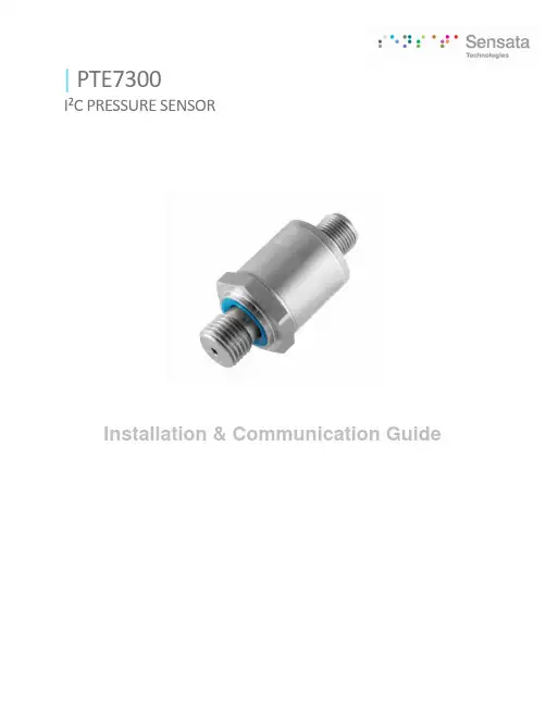
|PTE7300I²C PRESSURE SENSORInstallation & Communication GuideDescriptionThe PTE7300 pressure sensor is the ideal customer solution for challenging measuring requirements for general applications in the mid and high-pressure ranges. The PTE7300 features a wide range of ports and provides an I2C digital pressure output.ElectricalPressure Ranges 0-16 bar to 0-600 bar (0-230 psi to 0-8700 psi)Pressure Reference Gauge (Module) and Sealed Gauge (fully hermetic sensor) Supply Voltage 2.7VDC to 5.5VDCDigital Interface I2C with CRC (memory integrity, and data transmission) Device Address 0xDA (including CRC)0x6C (excluding CRC)Operating Current In SleepMode6.5 uA (typical)Operating Current In ActiveMode3.7mA typical (4mA maximum)Available Data PressureBridge temperature*Status synchronizedDevice serial (int16, at address 0x30) min./max. of span mapped to ±16000 bit value(int16, at address 0x2E)-40̊C..+125̊C mapped to±16000 bit value(uint16, at address 0x32) (uint32, at address 0x50 (low word), and address 0x52 (high word))Resolution Note: Sensata offers a C++ library available on request that is written on Arduino platform, which allows for plug-n-play sensor control and is easy to port to other platforms.15 bitResponse Time (default) < 1 msProbe Configurations Continuous or On-demand / single cycle*Note: the bridge temperature is not part of the production quality control routines. Sensata will not guarantee any performance ratings for the sensor’s temperature output. For accurate and reliable temperature measurement, it’s advised to use a different sensor with qualified temperature output.Typical Application CircuitNote: the pull-up resistor resistance values and cable length highly depend on the application. Typical pull-up resistors are 4.7kOhm for a cable between 1-2 meters. Please note that, in general, a low internal resistance and low internal capacitance cable will increase the action radius since, in that case, the voltage is dropping less over distance. Also, lowering the resistancevalues increases the current which sharpens the edges of the digital communication signals, but at costof power consumption when communicating with the device.I 2C outputPTE7300 SERIESContents1Pin Assignments (5)2Pin Descriptions (5)3Absolute Maximum Ratings (5)4I2C interface (6)4.1 Device Address (6)4.2 Command Format (7)4.3 System Operation Modes and State Diagram (9)4.4 I2C Bus Timing (9)5Revision History (10)1 PIN ASSIGNMENTSFigure 1. Pin Assignments – Top View2PIN DESCRIPTIONSTable 1. Pin DescriptionsPin Pin Name Type Description1 ALARM Output End of conversion or status output2 VSUPPLY S Supply voltage3 GND S Ground4 SDA Input/output I2C serial data in/output as fixed function.5 SDC Input/output I2C clock input as fixed function.M12x15-POLE MODULE3ABSOLUTE MAXIMUM RATINGSThe absolute maximum ratings are stress ratings only. The sensor might not function or be operable below and above the recommended operating conditions given in Table 2. Stresses exceeding the absolute maximum ratings will change the sensor accuracy; lead to imprecision, and eventually cause irreversible damage to the device. In addition, extended exposure to stresses above the recommended operating conditions might affect device reliability. Sensata does not recommend designing to the “Absolute Maximum Ratings.”Table 2. Absolute Maximum RatingsSymbolParameterMinimumMaximumUnitsVSUPPLY Maximum Analog Supply Voltage -0.3 6V VD_IO Maximum Voltage at all Digital I/O Pins-0.3 VSUPPLY+0.3SUPPL But ≤ 6 VTOPERATION Operation Temperature -40 100 °C TSTORStorage Temperature-40125°C4 I 2C INTERFACETable 3. Operating ConditionsNo.DescriptionSymbolMinTypMaxUnit1 I²C clock frequency I 2C _F_SCK400kHz 2 I²C clock low time (tLO) I 2C_T_LO 1300 ns 3 I²C clock high time (tHI)I 2C_T_HI 600 ns 4 I²C (repeated) start condition hold time (tSH)I 2C_T_SH 600 ns 5 ²C data setup time (tSU) I 2C_T_SU 100 ns 6 I²C data hold time (tH) I 2C_T_H 0 ns 7 I²C repeated start setup time I 2C_T_RSH 600 ns 8 I²C stop condition setup time (tLO) I 2C_T_PSU 600ns 9 I²C rise time (tR) I 2C_T_R 300 ns 10 I²C fall time (tF)I 2C_T_F 300 ns 11 I²C bus free time between STOP and START conditions (tBUF)I 2C_T_BUF 600 ns 12Pulse width of spikes suppressed by the I²C input filter*)I 2C_T_SSP500nsThe I 2C child interface provides direct access to the entire memory map of the IC. An external I 2C parent (e.g. a μC) can read and write all memory addresses (registers) of the device using the following commands:• Random write: Sets a memory address and writes data to consecutive memory addresses of the device starting at the set memory address.• Random read: Sets a memory address and reads data from consecutive memory addresses of the device starting at the set memory address.• Read last: Reads data from the device starting at the last memory address set by the parent. This facilitate s repeated reading of the same memory addresses without transmitting a memory address first.All read/writes must start at word aligned addresses (i.e. LSB of memory address equals 0) and read/write an even number of bytes . Maximum length for CRC protected read/writes is 4 bytes.4.1 Device AddressTable 4. Address DefinitionDevice address 0XDA Including CRC 0X6CExcluding CRC4.2 Command FormatCommands of I 2C EEPROM compatible protocolCommands of CRC protected protocolExample:I 2C random read exampleI2C random write exampleI2C random read with CRC exampleI2C random write with CRC exampleNOTE: the CRC4 and CRC8 fields are computed in the same bit and byte order as the transmission over the bus. Their polynomials are:•CRC4 polynomial 0x03, initialization value 0x0F•CRC8 polynomial 0xD5, initialization value 0xFFIf the CRC4 sent by the I2C parent does not match the CRC4 calculated by the I2C child, the I2C frame is aborted by not sending an acknowledge bit from the child after the CRC4. Additionally, the CRC4 error is reported as the event bit 11 at the STATUS register. If a command is aborted by a CRC4 error, no ‘read last’ command must follow.4.3System Operation Modes and State DiagramSystem balances performance and current consumption by different operation mode configurations. The Figure shows the Sensor state diagram.sent to Description0x7BBA (Idle) Puts the device into power state idle. Aborts any conversion inprogress. The timer counting down the period will be reset.0x8B93 (Start) Starts a measurement and put the chip into power state run.0xB169 (Reset) Performs a rest with complete power up sequence0x6C32 (Sleep) Enter the power state sleep.4.4I2C Bus TimingI2C Bus Timing Behavior5PLUG-N-PLAY C++ CLASS LIBRARY5.1Installing the library (Arduino IDE)The PTE7300_I2C library folder should be copied to the local user’s\Documents\Arduino\libraries\ folder to be visible inside Arduino IDE. Example sketches are added for guidance.The C++ library can also easily be ported to other platforms by rewriting only the constructor and the low-level readRegister and writeRegister methods source code, to modify the interface driver. The higher-level methods remain the same.5.2Example Arduino code – reading pressure output1.Create class instance ‘mySensor’2.Reserve signed 16 bit integer memory for the pressure value3.Initialize serial interface to readout printed messages on the USB interface4.Check if the sensor communication is ok, using the ‘isConnected’ method5.Readout the pressure value (‘mySensor.readDSP_S’ method) and store the value in thepre-allocated memory of the microchip6.Print the value on the USB interface to readout on the connected PC7.If no device is connected, do nothing, and notify the PC that no device has been found| PTE7300I²C PRESSURE SENSOR11C opyright © 2021 Sensata Technologies, Inc.Sensata Technologies, Inc. (“Sensata”) data sheets are solely intended to assist designers (“Buyers”) who are developing systems that incorporate Sensata products (also referred to herein as “components”). Buyer understands and agrees that Buyer remains responsible for using its independent analysis, valuation, and judgment in designing Buyer’s systems and products. Sensata data sheets have been created using standard laboratory conditions and engineering practices. Sensata has not conducted any testing other than that specifically described in the published documentation for a particular datasheet. Sensata may make corrections, enhancements, improvements, and other changes to its data sheets or components without notice.Buyers are authorized to use Sensata datasheets with the Sensata component(s) identified in each particular datasheet. HOWEVER, NO OTHER LICENSE, EXPRESS OR IMPLIED, BY ESTOPPEL OTHERWISE TO ANY OTHER SENSATA INTELLECTUAL PROPERTY RIGHT, AND NO LICENSE TO ANY THIRD PARTY TECHNOLOGY ORINTELLECTUAL PROPERTY RIGHT, IS GRANTED HEREIN. SENSATA DATASHEETS ARE PROVIDED “AS IS”. SENSATA MAKES NO WARRANTIES OR REPRESENTATIONS WITH REGARD TO THE DATASHEETS OR USE OF THE DATASHEETS, EXPRESS, IMPLIED, OR STATUTORY, INCLUDING ACCURACY OR COMPLETENESS. SENSATA DISCLAIMS ANY WARRANTY OF TITLE AND ANY IMPLIED WARRANTIES OF MERCHANTABILITY, FITNESS FOR A PARTICULAR PURPOSE, QUIET ENJOYMENT, QUIET POSSESSION, AND NON-INFRINGEMENT OF ANY THIRD PARTY INTELLECTUAL PROPERTY RIGHTS WITH REGARD TO SENSATA DATASHEETS OR USE THEREOF.All products are sold subject to Sensata’s terms and conditions of sale supplied at SENSATA ASSUMES NO LIABILITY FOR APPLICATIONSASSISTANCE OR THE DESIGN OF BUYERS’ PRODUCTS. BUYER ACKNOWLEDGES AND AGREES THAT IT IS SOLELY RESPONSIBLE FOR COMPLIANCE WITH ALL LEGAL, REGULATORY, AND SAFETY-ELATED REQUIREMENTS CONCERNING ITS PRODUCTS, AND ANY USE OF SENSATA COMPONENTS IN ITS APPLICATIONS, NOTWITHSTANDING ANY APPLICATIONS-RELATED INFORMATION OR SUPPORT THAT MAY BE PROVIDED BY SENSATA.Mailing Address: Sensata Technologies, Inc., 529 Pleasant Street, Attleboro, MA 02703, USAAmericas+1 (800) 350 2727 ***************************************Europe, Middle East & Africa +359 (2) 809 1826****************************Asia Pacific*************************.com China +86 (21) 2306 1500 Japan +81 (45) 277 7117 Korea +82 (31) 601 2004 India +91 (80) 67920890Rest of Asia +886 (2) 27602006 ext 28085.3 Class description (UML)The constructor will automatically set the nodeAddress attribute to the default value. A ‘bUseCRC’ attribute is a boolean flag that is by default true, which controls the CRC checking state on the communication messages. The CRC checking feature can be disabled by means of the ‘CRC’ method if needed.The ‘isConnected’ method is a simple and useful feature to check if the device is responding, prior to communicating with the device, to prevent bus failures or blocking drivers that wait forever. The last set of methods is used to readout information from the device.6 REVISION HISTORYRevision DateDescription of Change March 18, 2021 Preliminary version.。
11FB-05NL网络变压器
MechanicalsUnless otherwise specified,all tolerances are ±0.25元冊科技股份有限公司 YUAN DEAN SCIENTIFIC CO., LTD.TITLE 10/100BASE-T SINGLE PORT SURFACEMOUNT MAGNETICSP/N11FB-05NLDATE2006/10/13REV .1.0PAGE NO1-3AP’PD DWNMU QIN HUISchematicsE LECTRICAL SPECFICATIONS@25℃:TURN RATIO(±2%): 1CT:1CTOCL(100KHz/0.1V@8mA): pin(16-14)&pin(11-9): 350uH MIN Cw/w(100KHz/0.1V):25pF MAXInsertion Loss(dB MAX): -1.0dB(1-100MHz), -3.0dB(140MHz) Return Loss(dBMIN):-16.0dB(5MHz), -16.0dB(30MHz),-13.5dB(40MHz),-11.6dB(50MHz), -10.0dB(60MHz), -10.0dB(80MHz) HI-POT:1650Vrms/0.5mA RoHS compliance:YESRef:BOM AC33元冊科技股份有限公司 YUAN DEAN SCIENTIFIC CO., LTD.TITLE 10/100BASE-T SINGLE PORT SURFACEMOUNT MAGNETICSP/N11FB-05NLDATE2006/10/13REV .1.0PAGE NO2-3AP’PD DWNMU QIN HUIThere is another option, if you could not accept the above 2 options.It is an open type 50% epoxy, but it is RoHS version and can withstand 250 +/-5degC.Pls refer to the below photos.Profile Feature Pb-Free AssemblyAverage Ramp-Up Rate(Ts max to Tp)30C /second max.Preheat-Temperature Min (Ts min)-Temperature Max (Ts max)-Time (ts min to ts max)1500C2000C60-180 secondsTime maintained above:-Temperature (T L)-Time (t L)2170C60-150 secondsPeak/Classification Temperature (Tp) 250±50CTime within 50C of actual PeakTemperature (tp)20-40 secondsRamp-Down Rate 60C/seconds maxTime 250C to Peak Temperature 8 minutes max.元冊科技股份有限公司YUAN DEAN SCIENTIFIC CO., LTD.TITLE 10/100BASE-T SINGLE PORT SURFACEMOUNT MAGNETICSP/N 11FB-05NL DATE2006/10/13 REV. 1.0 PAGE NO 3-3 AP’PD DWN MU QIN HUI。
UL2556中文翻译
UL2556 2011译版通过UL UL安全标准的保护。
既不是一个标准的打印副本,也分布一个标准的软盘和分布软盘上的标准文件的软盘应以任何方式改变。
所有UL的标准和所有,所有权,和权利有关这些标准应保持了UL的唯一和排他性的财产。
保留所有权利。
本出版物的任何部分进行复制,存储在检索系统中,或任何形式的任何手段,电子,机械复印,录音,或以其他方式传播未经事先批准的UL。
UL安全标准的修订,不时发出。
一个是最新的UL安全标准只有当它采用了最近通过的修订。
UL提供本标准平方米²,没有任何形式的的担保,明示或暗示,包括但不限于对适销性或为任何目的的隐含担保。
在任何情况下,UL认证的任何特殊,偶然,必然,间接或类似的损害承担责任,包括利润损失,储蓄损失,数据丢失,或任何因使用或其他损害无法使用这个标准,即使UL或授权的UL代表的建议这种损害的可能性。
在任何情况下,UL的任何损害赔偿责任,不断超过支付的价格这个标准,无论索赔的形式。
UL将尝试回答有关其标准的电子版本的支持请求。
然而,这支持服务是提供一个合理的努力的基础上,和UL未必能解决所有支持请求。
只有他们正在使用的UL认证支持其标准的电子版本条件和操作系统,它的目的是。
UL的扶持政策可能会改变时间到时,恕不另行通知。
UL保留权利更改的格式,简报,文件类型和格式,交货方式和格式,和它的印刷版和电子标准,恕不另行通知。
UL安全标准的电子版本,买方同意维护,保障,并举行UL认证无害和反对任何损失,费用,责任,损失,索赔,或判决(包括合理的律师费)引入任何错误或偏差造成的,而买方存储购买者的计算机系统上的电子标准。
如果购买一个单用户版电子标准,本标准的一个副本可以存储在一台个人计算机的硬盘,或在一个单一的局域网的文件服务器或永久存储在这种方式的多用户电脑设备,这一标准只能由一个用户访问的时间和为没有多个并发访问的可能性。
如果多用户版电子标准购买,可以存储在一个标准的副本一个单一的局域网文件服务器,或在多用户计算机的永久性存储设备,或Intranet 服务器。
讯飞网维 信号特克 千兆以太网性能测试仪 说明书
SIGNAL TEK™Cable Performance T esterI Gigabit PerformanceQualification – Test toIEEE 802.3 standardsI Selectable PerformanceT esting – qualify performanceof Data, Voice over IP, andIP Video applicationsI Performs Gigabit Ethernetlink establishment test in10 secondsI Data Monitoring to detectintermittent network problemsI Smart Autotest Functiondetects the presence of theSIGNAL TEK remote, activenetwork device or open endedcable and automatically runsthe appropriate test suiteI Intuitive Graphical UserInterface for fast andeasy operationI Internal and USBData Storage –store 20,000 tests internallyor unlimited on USB driveI Prints Easy-to-Read Pass/Fail Qualification ReportsSIGNALTEK™– High-Performance Gigabit Ethernet TestingSIGNALTEK™is the most cost-effective Gigabit Ethernet cableAutotest key to initiate tests from the remote end for one personoperation2.8Љ(7.1cm) 1⁄4VGA Color Display with backlighting for use in low light conditionMulti-color LEDs indicate link status,loopback mode,10/100 and Gigabit device detection,Autotest pass/fail,and battery conditionEasy-to-navigate user interfaceCompact design and soft over-mold sides fit well into any sized handContext sensitive softkeysSingle button cable testingQuick navigation key returns to Job Manager screenSingle button push for active network testing and monitoring Port status function detects 10/100 or Gigabit Ethernet devicesDisplays result for last autotest via red or green LED indicationSIGNAL TEK ™Standard KitCatalog No. 33-974I1 SIGNALTEK ™Near-end and remote-end handset IDEAL INDUSTRIES, INC.03/06Printed in U.S.A.ISO 9001:2000 QMSNo. 33-974SIGNALTEK ™OptionalPower Adapter – 4010-00-0136DESCRIPTION CAT NUMBER SIGNALTEK™ Cable Performance Tester 33-974Replacement cable accessory kit –Contains all original cables in SIGNALTEK™ kit 1219-91-0003RJ45 to 8 head alligator clipK-7920OPTIONALUniversal (120-240V) AC-DC power adapter (1)4010-00-0136。
M-511
M-511⁄8 DIN Digital Panel RTD MetersThe DP63000-RTD meter accepts standard RTD inputs and precisely linearizes them into temperature readings. A full 4-digit display accommodates a wide range of temperature inputs. State-of-the-art digital circuitry virtually eliminates errors due to drift. The meter features a readout choice of either Fahrenheit or Celsius with 0.1 or 1° resolution. Display prompts and front panel buttons aid the operator through set-up and operation. Programmable digital filtering enhances the stability of the reading. All set-up data is stored in EEPROM, which will hold data for a minimum of 10 years without power. The meter provides a peak “HI” and valley “LO” reading memory with selectable capture delay time. The capture delay is used to prevent detection of false peak or valley readings that may occur during start-up or unusual process events. The peak and valley readings areDP63200-RTDU RTD Meter U 4-Digit, 14.2 mm (0.56") LEDU Accepts Standard 3-Wire 100 Ω RTD Sensors (ALPHA = 0.00385 or ALPHA =0.00392) U Conforms to ITS-90 StandardsU Selectable °F or °C with 0.1 or 1 Degree Display Resolution U P rogrammableTemperature Offset U Programmable Digital FilteringU Peak/Valley (High/Low Reading) Memory U NEMA 4X (IP65) Sealed Front BezelU Custom Units Overlay with BacklightOrdering Example: DP63200-RTD, RTD input, 85 to 250 Vac, 50/60 Hz.stored at power-down, allowing process limits to be monitored over any length of time. The meter has several built-in diagnostic functions to alert operators of any malfunction. Extensive testing of noise interference mechanisms and full burn-in makes the meter extremely reliable in industrial environments. The front bezel meets NEMA 4X (IP65) requirements for wash-down applications.Specifications Display: 4-digit, 14.2 mm H (0.56") LED, minus sign displayed for negative temperatures Power: 85 to 250 Vac, 50/60 Hz, 6 VA Isolation: 2300 Vrms for 1 minute between input and supply (300V working voltage)Resolution: 0.1 or 1°Range (Decimal Point Dependent): 0.1° Res: -199.9 to 850.0°C (-199.9 to 999.9°F) 1° Res: -200 to 850°C (-328 to 1562 °F)Lead Resistance Effect: 20 Ω max, 2.5 °C/Ω error for V exc and common lead unbalance Accuracy: 0.3°C, @ 23°C and 30 minute warm-up Reading Rate: 2.5 readings/s Response Time: 2 s to settle for step input (increases with programmable digital filtering)Low-Frequencey Noise Rejection: Normal Mode Rejection: 40 dB @ 50/60 Hz (may be improved by programmable digital filtering) Common Mode Rejection: 120 dB, DC to 50/60 Hz Environmental Conditions: Operating Temperature Range: 0 to 50°C (32 to 122°F) Storage Temperature Range: -40 to 80°C (-40 to 176°F) Operating and Storage Humidity: 85% max RH non-condensing from 0 to 50°C (32 to 122°F)Span Drift: 50 ppm/°C Zero Drift: 0.001°C/°C Altitude: Up to 2000 m (6562')Construction: This unit is rated for NEMA 4X (IP65) indoor use, 1 piece bezel/case, flame-resistant—panelgasket and mounting clip included Connections: High-compression, cage-clamp terminal block Dimensions: 104.1 D x 91.4 W x 44.5 mm H (4.10 x 3.50 x 1.75)Weight: 0.24 kg (0.65 lb)DP63200-RTD shown actual size.。