手压阀(论文)说明书
手电动密闭阀说明书(详实材料)

一、用途D940J-0.5系列手电动密闭阀门是有一定抗冲击波余压能力的专用防护设备,用于防护工程的进风和排风系统上,安装于水平或垂直的管道上,使用时要求阀门全启或全闭,不能作调节气流用。
公称压力不大于0.05MPa ,工作温度在-30°C —+40°C 之间,相对湿度30—40%,介质为空气,为单向闭路机构。
二、D940J-0.5系列手电动密闭阀门型号及主要技术参数三、D940J-0.5系列手电动密闭阀门结构特点及工作原理:D940J-0.5系列手电动密闭阀门主要由电动装置、电动阀门控制器和密闭阀门三部分组成;其工作原理为:当战时需要进行隔绝防护时,按下电动阀门控制器上的关阀按键,通过阀杆转动使阀门关闭,通过电动阀门的行程控制机构,锁紧阀门保证密封;也可转动手轮,通过阀杆转动使阀门关闭保证密封。
D940J-0.5系列手电动密闭阀门主要外形尺寸与连接尺寸:D940J-0.5系列手电动密闭阀门外型尺寸图:如左图所示:序号 型号 风量(m 3/h )重量(Kg )V=6m/s V=8m/s 1 D940J-0.5-200 678 904 31 2 D940J-0.5-300 1526 2034 48 3 D940J-0.5-400 2713 3617 67 4 D940J-0.5-500 4239 5652 106 5 D940J-0.5-600 6104 8139 75 6 D940J-0.5-800 10852 14469 126 7D940J-0.5-10001695622608160D940J-0.5系列手电动密闭阀门外型尺寸表(mm)规格L0 L1 L2 D D1 D2 n d DN200 672 118 472 270 215 250 8 9 DN300 781 145 521 385 315 360 9 11 DN400 945 175 598 515 441 490 12 12 DN500 1095 225 665 650 560 622 12 14 DN600 1081 275 706 750 666 720 12 14 DN800 1271 290 801 950 870 920 16 17 DN1000 1606 300 1016 1205 1090 1160 20 18 四、D940J-0.5系列手电动密闭阀门电动装置主要由电机、减速器、行程控制机构、转矩控制机构、开度指示机构、手轮和机械限位机构组成。
一份涉及压力阀门的产品说明书

INTRODUCTIONFollow these instructions when installing and operating the product.APPLICATION LIMITSThese products are intended for use in general purpose compressed air systems only.Operating Inlet Pressure RangeOperator TypePressure Range:kPa PSIG BARSolenoid, Air Pilot, Air Pilot w/ Prestolok Adapter Minimum 40060 4.0Maximum 103515010.3High Pressure Air Pilot Minimum 40060 4.0Maximum 172425017.2High Pressure Air Pilot w/Prestolok Adapter Minimum 40060 4.0Maximum 172425017.2See caution statement below for all valves with Prestolok Adapters CAUTION: The maximum pressure rating for all valves withPrestolok adapters is shown above. The actual maximum pressure is dependent upon the type of tubing that is used. Soft Start valves with Prestolok fittings must use Parker PARFLEX tubing 1/4” OD, which has the required OD tolerances.Ambient Temperature RangeOperator TypeAmbient Temperature Range:°C °FSolenoid Minimum 0°C 32°F Maximum 60°C 140°F Air Pilot Minimum 0°C 32°F Maximum 70°C 160°F Air Pilot with Prestolok AdapterMinimum 0°C 32°F Maximum 65°C 150°F (See Caution statement below)CAUTION: The rating of 32° to 150°F, (0° to 65°C), is the ratingof the valve with a Prestolok fitting. The actual minimum and maximum temperatures are dependent upon the type of tubing that is used. Soft Start valves with Prestolok fittings must use Parker PARFLEX tubing 1/4”OD, which has the required OD tolerances.Voltage Range:The voltage range is -15% to +10% of the nominal rated voltage.INSTALLATION / OPERATING INSTRUCTIONS06 or 07 valves should be installed with reasonable accessibility for service whenever possible. Keep pipe or tubing lengths to a minimum with inside clean and free of dirt and chips. Pipe joint compound should be used sparingly and applied only to the male pipe never into the female port.Do not use Teflon †tape to seal pipe joints pieces have a tendency to break off and lodge inside the unit, possibly causing malfunction. Care should be taken to avoid undue strain on the valve.Air applied to the valve must be filtered to realize maximum component life.Life Expectancy - Normal multi-million cycle life expectancy of these valves is based on the use of properly filtered and lubricated air at room temperature. These valves are also designed to operate under non-lubricated conditions and will yield millions of maintenance free cycles.Factory Pre-Lubrication - Valves are pre-lubricated at assembly with a petroleum based grease which has a lithium content.In-Service Lubrication - In-service lubrication is not required; however, if lubrication is to be used, Schrader Bellows F442 oil is recommended. This oil is specially formulated to provide peak performance and maximum service life from all air operated equipment. Otherwise, use an air line lubricant (compatible with Nitrile & Polyurethane seals) which will readily atomize and be of the medium aniline type. Aniline point range must bebetween 180° and 220° F. Viscosity at 100° F: 140 - 170 SUS.CAUTION: Do not use synthetic, reconstituted, or oils with an alcoholcontent or detergent additive.CAUTION: Do not restrict the inlet of valves having an internal pilotsupply. Pressure supply piping must be the same size as the inlet port or larger to insure that the pilot valve receives sufficient pressure supply during high flow conditions.FUNCTIONThe Soft Start valve is a 3-port valve which supplies air in a controlled reliable manner to pneumatic systems and has the quick exhaust features of a dump valve . This valve replaces conventional main valves.The Soft Start valve operates much like a standard 3-Way valve. When the valve is installed port 2 is connected to port 3 (downstream system is exhausted to atmosphere). When a signal, (pneumatic or electric depending upon pilot operator) is received in port 12, the connectionbetween port 2 and 3 is closed. At the same time, supply air from port 1 isconnected to port 2 through the adjustable throttle, (Flow Control Screw). When the downstream pressure reaches a specific point, the main poppet opens and permits full air flow through the valve. The table shows the relationship between theinlet pressure and the downstreampressure at which the main valveopens.When the pilot signal is removed, the valve returns to its initial position and the downstream air is dumped rapidly through port 3.Installation andOperating Instructions K583432Soft Start ValveIssued: March, 1997Supersedes January, 1997P.O. Box 631Akron, Ohio 44309-0631!!!!Inlet Pressure:DownstreamPressure forFull Flow75 psig 50 psig100 psig 55 psig125 psig 60 psig150 psig 65 psig250 psig 85 psigINSTALLATIONThe Soft Start valve replaces an ordinary main valve; therefore, it is usually mounted between the air preparation unit and the system. The Soft Start valve is specifically designed to mount directly in line with the†Trademark E.I. DuPont de Nemours & Co.Schrader Bellows 06/07 Series PREP-AIR II Modular Air Preparation Units using modular body connectors. The valve can also be mounted with the aid of two screws, (sizes #10-32 or M6 are recommended).Note:When installing the valve, make sure that the Flow Control Screwis easily accessible.PORT CONNECTIONS1) Connect inlet air supply to port 1.2) Connect mufflers (or plumb exhaust) from port 3.3) Connect cylinder port 2 to cylinder or other system devices to besupplied air.4) Signal Connection - Soft Start valves may be remotely controlledelectrically or pneumatically.a) For solenoid pilot operated valves, see the instructions under“WIRING INSTRUCTIONS.”b) For air pilot operated valves, connect the air line to the pilot port12, ( 1/8” NPTF ). If using a valve with a Prestolok fitting, connect Parker PARFLEX 1/4” OD tubing by fully inserting the tubing into the Prestolok fitting, (see following Note).Note: Be sure to use the tubing support, (part no. 63 PTU), whenusing series U polyurethane tubing. All applications should be carefully tested through the full range of conditions which may be encountered prior to use.ANSI SYMBOLSWIRING INSTRUCTIONSNOTE: In addition to the following instructions, follow all requirements for local and national electrical codes.Attach an electrical cable with connector (that conforms to the DIN 43650,Form C pattern) to the terminals of the solenoid. For locations in a cabinet or other protected environment, the Snap-On connector with loose wires may be attached. In both cases, do not attach or remove the connectors until power is off.ELECTRICAL CONNECTIONValves with 3-pin male terminals should have power connected to the parallel terminals. Ground should be connected to the perpendicularterminal. Use only connectors that comply with DIN 43650, Form C (8 mm blade spacing).OVERRIDE OPERATIONThe flush non-locking manual override is located on the body of thesolenoid pilot. To operate the override, place a small screwdriver in the slot of the override and turn approximately 45° in either direction until the solenoid pilot actuates. The solenoid pilot will remain actuated until the override is released. When released, the solenoid pilot de-actuates.SOLENOID REPLACEMENTTo replace the solenoid, remove the two mounting screws and replace with the correct voltage solenoid. Tighten new screws 5 to 6 in/lbs.Voltage Coil No.Voltage Coil No.12/60P025422B4024VDC P025422B4924/60P025422B42120/60P025422B5312VDC P025422B45240/60P025422B57ACCESSORIESKit No.DescriptionPS754SB 06 Series Modular Body Connectors PS854SB 07 Series Modular Body Connectors 480810001/2 “ Exhaust MufflerPS298305SB Snap on Connector Kit with 0.5 meter wires PS298320SB Snap on Connector Kit with 2 meter wires PS2932SB 3-Pin Connector Kit - UnlightedPS294675SB 3-Pin Connector Kit - Lighted, 12VAC & DC PS294679SB 3-Pin Connector Kit - Lighted, 24VAC & DC PS294683SB 3-Pin Connector Kit - Lighted, 120VACPS2932JSB 3-Pin Connector Kit - Unlighted with 2 meter cord PS2946J75SB 3-Pin Connector Kit - Lighted, 12VAC & DC with 2meter cordPS2946J79SB 3-Pin Connector Kit - Lighted, 24VAC & DC with 2meter cordPS2946J83SB3-Pin Connector Kit - Lighted, 120VAC with 2 meter cord∅ 0.26Mount directly in line with FRL’s by using the Modular mounting system,or use holes forside mountingPorts 1 and 23/8” 06 Series 1/2” 07 Series Port 3 - 1/2”K583432EXTRA COPIES OF THESE INSTRUCTIONS ARE AVAILABLE FOR INCLUSION IN EQUIPMENT / MAINTENANCE INSTRUCTION MANUALS THAT UTILIZE THESE PRODUCTS. CONTACT YOUR LOCAL REPRESENTATIVE.。
手压阀说明书

手压阀设计
一、工作原理
手压阀是开启或关闭液路的一种手动阀门。
手柄向下压紧阀杆时,弹簧受压,阀杆向下移动,使入口和出口相通,阀门打开;松开手柄,因弹簧力作用,阀杆向上压紧阀体,入口与出口不通,阀门关闭。
二、机构功能
手压阀用来控制流体的方向、压力、流量的装置。
阀门是使配管和设备内的介质液体、流动或停止、并能控制其流量的装置。
主要用于手动改变压力大小,从而达到手动变速的目的。
三、手压阀手柄设计
图1.13手柄草图
退出草图绘制界面选择[特征]-[拉伸]选择图1.15中阴影为拉伸轮廓,设置参数如图1.16
图1.15要拉伸的轮廓图1.16 拉伸参数
选择[特征]-[拉伸]选择图中阴影为拉伸轮廓如图1.17,设置参数如图1.18
图1.17拉伸3轮廓图1.18拉伸3参数
选择手柄端面为绘图面绘制直径为5的圆如图1.19
图1.19 直径为5的圆
退出绘图界面选择[特征]-[拉伸]以刚绘制的圆为轮廓深度为5mm拉伸出一个圆柱。
并选择[插入]-[注解]-[装饰螺纹线]以刚拉伸的圆柱端面外圆为圆形边线,次要直径为3.75mm深度为5mm绘制装饰螺纹线。
选择[特征]-[圆角]以拉伸1中的个边线为基准对实体进行倒圆角,最后选择材料为HT20绘制手柄如图1.20。
图1.20 手柄
四、创新点
在此次设计过程中将弹簧零件的绘制安排在其他各零件装配完成之后,通过采用上下两支撑面间的相对距离来定义弹簧的长度,从而使系统可以计算出弹簧在上下两个支撑面不同的状态下的长度,以此来实现弹簧的伸缩。
手动操作阀说明书

Manually operated valvesManually operated valvesKey featuresInnovative Versatile Reliable Easy to install• Small and compact for a wide rangeof pneumatic applications• Numerous valve functions can beselected: 3/2-way and 5/2-wayfunctions• With flow rates of up to 600 l/min,the valves offer outstanding pneu-matic performance for a wide rangeof applications• Lightweight• Minimal actuating forces• Flexibility of the pneumatic workingports provides a practical solutionto different requirements• Round silencer for ducted exhaustair• Suitable for vacuum in some cases• Reverse operation possible in somecases• Actuation: direct• Pressure range from vacuum to10 bar possible• Versions:– Pushbutton valve– Toggle lever valve– Hand lever valve– Finger lever valve– Foot valve• Durable thanks to tried-and-testedpoppet valves• Sturdy thanks to metal or plastichousing and connecting thread orconnector• Front panel mounting or mountingon bracket2d Internet: /catalogue/...Subject to change – 2020/0732020/07 – Subject to changed Internet: /catalogue/...Manually operated valvesCharacteristics43[1] Finger lever, pushbutton, togglelever, button switch, foot pedal as actuator[2] Fast mounting: via retainingbracket or screwed directly via through-hole, front panel mount -ing possible in some cases[3] Practical connection via threadedconnection or connector [4] Various widthsEquipment options 3/2-way valve 5/2-way valve • Normally open/closed • Mechanical spring• Vacuum operation possible • Directly actuated • Ducted exhaust air •Detenting (bistable) or non-detenting (monostable)• Mechanical spring• Vacuum operation possible • Directly actuated • Ducted exhaust air •Detenting (bistable) or non-detenting (monostable)4d Internet: /catalogue/...Subject to change – 2020/07Manually operated valvesPeripherals overviewManually operated valves 3/2-way pushbutton valve13/2-way foot valve F-3_M5 ...3/2-way toggle lever valve KH/O-3-PK143Manually operated valves Key featuresManually operated valvesManually operated valves are used in all industrial sectors, as well as in the skilled trades. They are used to carry out simpleprocesses such as clamping or closingsafety doors.Depending on the required actuation(pushing, rotating/swivelling or tilting),the valves are either resetting ornon-resetting.The valves are directly actuated.5 2020/07 – Subject to change d Internet: /catalogue/...Manually operated valvesKey features-NoteH-A filter must be installed upstream of valves operated in vacuum mode. This prevents any foreignmatter in the intake air getting into the valve (e.g. when operating a suction cup with connector).6d Internet: /catalogue/...Subject to change – 2020/07Manually operated valves Data sheet – Pushbutton valve-M-Flow rate80 l/min-L- Pressure–0.95 ... 8 bar -Q-Temperature range–10 ... +60°C Mounting either via through-hole or onfront panel (in the case of F-3-M5 withflange eyes)F-3-M5M52.02357.0––1)PK-3 = barbed fitting for plastic tubing with 3 mm nominal widthH--NotePushbutton valves are only to be operated manually.7 2020/07 – Subject to change d Internet: /catalogue/...Manually operated valvesData sheet – Pushbutton valve8d Internet: /catalogue/...Subject to change – 2020/07Manually operated valves Data sheet – Toggle lever valve-M-Flow rateMounting via through-hole Array80 l/min-L- Pressure0 ... 8 bar-Q-Temperature range–10 ... +60°C1)9 2020/07 – Subject to change d Internet: /catalogue/...Manually operated valvesData sheet – Toggle lever valve10d Internet: /catalogue/...Subject to change – 2020/07-M-Flow rate80 ... 600 l/min -L- Pressure–0.95 ... 10 bar -Q-Temperature range–10 ... +60°CMounting via through-holeTH-3-1/4-B6003/2-way valvePoppet valve, directly actuatedG1/47.021010.5––1)PK-3 = barbed fitting for plastic tubing with 3 mm nominal width-M-Flow rate550 ... 600 l/min -L- Pressure–0.95 ... 10 bar -Q-Temperature range–10 ... +60°C Mounting either via through-hole or onfront panelH-3-1/4-B6003/2-way valvePoppet valve, directly actuatedG1/4320-M-Flow rate550 ... 600 l/min -L- Pressure–0.95 ... 10 bar -Q-Temperature range–10 ... +60°C Mounted via flange eyes on thehousingFoot valves with detent are actuated bymeans of a foot lever with mechanicaldetent. The valve engages when it isfirst actuated, and when the foot leveris actuated again, the valve returns toits normal position.F-3-1/4-B FO-3-1/4-B6003/2-way valvePoppet valve,directly actuatedPoppet valve,directly actuatedPoppet valve,directly actuatedG1/4G1/47.07.059559550.055.0Ordering data – Foot valveAccessories1)Packaging unitFesto - Your Partner in AutomationConnect with us/socialmedia 1Festo Inc.2Festo Pneumatic 3Festo Corporation 4Regional Service Center 5300 Explorer DriveMississauga, ON L4W 5G4CanadaAv. Ceylán 3,Col. Tequesquináhuac 54020 Tlalnepantla, Estado de México1377 Motor Parkway Suite 310Islandia, NY 117497777 Columbia Road Mason, OH 45040Festo Customer Interaction CenterTel:187****3786Fax:187****3786Email:*****************************Multinational Contact Center 01 800 337 8669***********************Festo Customer Interaction Center180****3786180****3786*****************************S u b j e c t t o c h a n g e。
手压阀发展现状论文

手压阀发展现状论文手压阀作为一种常见的水龙头设备,发展至今已有很长的历史。
本文将从手压阀的起源、发展历程和现状等方面进行探讨,以期对手压阀的发展有一个全面的了解。
手压阀最早起源于古代希腊,当时的人们使用石头或陶器等材料制作手压阀,用于控制水流的开关,以满足他们的生活需求。
随着人类文明的发展,手压阀逐渐进化成为现代使用的金属材料制作的水龙头设备,并广泛用于家庭、商业和公共场所等领域。
随着科技的进步和社会的发展,手压阀经历了许多创新和改进。
传统的手压阀通常使用橡胶内置物来控制水流,但这种设计存在一定的问题,比如容易磨损、易滋生细菌等。
为了解决这些问题,现代手压阀采用了更先进的材料,如不锈钢和陶瓷等,提高了阀门的耐久性和抗菌能力。
此外,手压阀还经历了形态和功能的改进。
在外观上,手压阀的设计变得更加简洁、美观,适应了人们对家居装饰的要求。
而在功能上,手压阀不仅仅可以控制冷热水的流量,还可以通过设置温度控制器,实现自动调节水温的功能,提供更多的便利。
目前,手压阀在市场上有着广泛的应用。
它们不仅被广泛应用于家庭生活中的卫生间、浴室等场所,还被应用于商务楼、酒店、医院和公共场所等,以满足人们对水龙头的高品质需求。
同时,手压阀还得到了节水型社会的赞誉,因为其独特的设计,使得只需轻轻一按,便可获得适量的水流,避免了水的浪费,对环境起到了积极的保护作用。
虽然手压阀已取得了显著的发展,但仍然面临一些挑战和待完善的地方。
首先,手压阀的价格相对较高,超出了一些消费者的负担能力,限制了其在市场上的推广和应用。
其次,手压阀的使用寿命还有待提高,需要进一步改进材料和设计,减少磨损和故障的发生。
此外,在一些特殊场合,如高温、高压等环境下,手压阀的使用还存在一定的风险和局限。
综上所述,手压阀作为一种常见的水龙头设备,经历了漫长的发展历程,并取得了显著的进步。
通过不断进行创新和改进,手压阀在材料、外观和功能等方面不断提升,满足了人们对高品质水龙头设备的需求。
Parker Hannifin 手动阀门系列CB技术信息汇报说明书
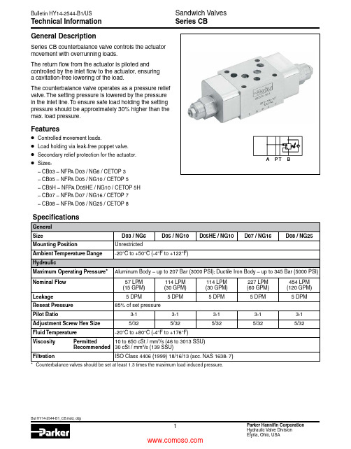
Technical InformationSeries CBGeneral DescriptionSeries CB counterbalance valve controls the actuator movement with overrunning loads.The return flow from the actuator is piloted and controlled by the inlet flow to the actuator, ensuring a cavitation-free lowering of the load.The counterbalance valve operates as a pressure relief valve. The setting pressure is lowered by the pressure in the inlet line. To ensure safe load holding the setting pressure should be approximately 30% higher than the max. load pressure.Features• Controlled movement loads.• Load holding via leak-free poppet valve.• Secondary relief protection for the actuator.• Sizes:– CB03 – NFP A D03 / NG6 / CETOP 3 – CB05 – NFP A D05 / NG10 / CETOP 5 – CB5H – NFP A D05HE / NG10 / CETOP 5H – CB07 – NFP A D07 / NG16 / CETOP 7– CB08 – NFPA D08 / NG25 / CETOP 8Ordering Information Series CBCounterbalanceValveCBCode Description AA in A BB in B DD in A and BCode Description03 NFPA D03 / NG6 05 NFPA D05 / NG10 5H* NFPA D05HE / NG10 07 NFPA D07 / NG16 08 NFPA D08 / NG25StyleSizePressure Range30C ode Description30 207 Bar (3000 PSI)**69 to 276 Bar (1000 to 4000 PSI)C ode Description A Aluminum DDuctile IronBody Material SealC ode Description N NitrileV* Fluorocarbon* Upon request.Weight:Size CB**AA30NA CB**AA30ND CB**BB30NA CB**BB30ND CB**DD30NA CB**DD30ND CB030.3 kg (0.8 lbs.) 1.1 kg (2.4 lbs.)0.5 kg (1.1 lbs.) 1.1 kg (2.4 lbs.)0.8 kg (1.7 lbs.) 1.5 kg (3.2 lbs.)CB05, CB5H 1.0 kg (2.3 lbs.) 2.2 kg (4.9 lbs.) 1.0 kg (2.3 lbs.)2.2 kg (4.9 lbs.) 1.5 kg (3.2 lbs.) 2.9 kg (6.4 lbs.)CB07 2.5 kg (5.6 lbs.)4.8 kg (10.6 lbs.) 2.5 kg (5.5 lbs.) 5.3 kg (11.8 lbs.) 3.6 kg (8 lbs.)7.3 kg (16.2 lbs.)CB085.3 kg (11.7 lbs.)11.8 kg (25.9 lbs.)5.9 kg (13.1 lbs.)13.3 kg (29.3 lbs.)7.9 kg (17.4 lbs.)16.2 kg (35.8 lbs.)CB**AA CB**BB CB**DD** Standard setting.* Valve comes with D05HE (ISO) pattern seal plate (990-120-012). If D05H pattern is required, order seal plate kit 990-120-009.CB03*CB05/CB5HCB03*CB05/CB5HCB03*CB05/CB5H1050602.613.215.930204070807.95.310.618.521.2Flow (Q)PSILPMGPMP r e s s u r e D r o p pD Pilot Pressure vs.Flow201060505.32.615.913.24030807010.67.921.218.5Flow (Q)LPMGPMP r e s s u r e D r o p pD Pressure Differential vs.Flow Fluid Viscosity 30 cSt at 50°C (122°F)1050602.613.215.930204070807.95.310.618.521.2Flow (Q)40PSI 80LPMGPM P r e s s u r e D r o p pD Pressure vs.Flow ReliefFluid Viscosity 30 cSt at 50°C (122°F)201001205.326.531.760408014016015.910.621.237.042.3Flow (Q)PSILPMGPMP r e s s u r e D r o p pD Pilot Pressure vs.FlowFlow (Q)P r e s s u r e D r o p pD 20605.315.9401208010010.631.721.226.5LPMGPMPressure Differential vs.Flow Fluid Viscosity 30 cSt at 50°C (122°F)201001205.326.531.7604080140160Flow (Q)40PSI 80LPMGPMP r e s s u r e D r o p pD Pressure vs.Flow ReliefFluid Viscosity 30 cSt at 50°C (122°F)CB07*CB08*CB07*CB08*CB07*CB08*4020024010.652.963.51208016028032031.721.242.374.184.7Flow (Q)PSI LPMGPMP r e s s u r eD r o p pD Pilot Pressure vs.FlowFlow (Q)P r e s s u r e D r o p pD 4012010.631.78024016020021.263.542.352.9LPMGPMPressure Differential vs.Flow Fluid Viscosity 30 cSt at 50°C (122°F)201001205.326.531.760408014016018020022015.910.621.237.042.347.652.958.2Flow (Q)40PSI 80LPMGPMP r e s s u r e D r o p pD Pressure vs.Flow ReliefFluid Viscosity 30 cSt at 50°C (122°F)25756.619.85012510013.233.126.5Flow (Q)200600PSI400800Bar LPMGPMP r e s s u r e D r o p pD Pilot Pressure vs.FlowFluid Viscosity 30 cSt at 50°C (122°F)20605.315.9401001208010.626.531.721.2Flow (Q)50LPMGPMP r e s s u r e D r o p pD Pressure Differential vs.Flow Fluid Viscosity 30 cSt at 50°C (122°F)20605.315.9401001208010.626.531.721.2Flow (Q)200PSIBar LPMGPMP r e s s u r e D r o p pD Pressure vs.Flow ReliefFluid Viscosity 30 cSt at 50°C (122°F)DimensionsCB03AA – Inch equivalents for millimeter dimensions are shown in (**)CB03BB –Inch equivalents for millimeter dimensions are shown in (**)Series CBDimensions Series CBSeries CB03DD – Inch equivalents for millimeter dimensions are shown in (**)CB05AA – Inch equivalents for millimeter dimensions are shown in (**)CB05DD – Inch equivalents for millimeter dimensions are shown in (**)CB5HBB –Inch equivalents for millimeter dimensions are shown in (**)* D05HE (Standard)** D05H* D05HE (Standard) Valve comes with D05HE (ISO) Pattern seal plate (990-120-012). If D05H pattern is required, order seal plate kit 990-120-009.Valve comes with D05HE (ISO) Pattern seal plate (990-120-012). If D05H pattern is required, order seal plate kit 990-120-009.CB07AA – Inch equivalents for millimeter dimensions are shown in (**)* D05HE (Standard)** D05Hseal plate kit 990-120-009.CB07DD – Inch equivalents for millimeter dimensions are shown in (**)CB08BB –Inch equivalents for millimeter dimensions are shown in (**)Parker Hannifin Corporation Hydraulic Valve Division 520 Ternes AvenueElyria, Ohio 44035 USATel: 440 366 5100Fax: 440 366 5253/hydraulicvalve Bulletin HY14-2544-B1/US,7/15© 2015 Parker Hannifin Corporation. All rights reserved.FAILURE OR IMPROPER SELECTION OR IMPROPER USE OF THE PRODUCTS DESCRIBED HEREIN OR RELA TED ITEMS CAN CAUSE DEA TH, PERSONAL INJURY AND PROPERTY DAMAGE.• This document and other information from Parker-Hannifin Corporation, its subsidiaries and authorized distributors provide product or system options for further investigation by users having technical expertise.• The user, through its own analysis and testing, is solely responsible for making the final selection of the system and components and assuring that all performance, endurance, maintenance, safety and warning requirements of the application are met. The user must analyze all aspects of the application, follow applicable industry standards, and follow the information concerning the product in the current product catalog and in any other materials provided from Parker or its subsidiaries or authorized distributors.• T o the extent that Parker or its subsidiaries or authorized distributors provide component or system options based upon data or specifications provided by the user, the user is responsible for determining that such data and specifications are suitable and sufficient for all applications and reasonably foreseeable uses of the components or systems.WARNING – USER RESPONSIBILITYThe items described in this document are hereby offered for sale by Parker-Hannifin Corporation, its subsidiaries or its authorized distributors. This offer and its acceptance are governed by the provisions stated in the detailed “Offer of Sale” elsewhere in this document or available at /hydraulicvalve.OFFER OF SALEFor safety information, see Safety Guide SG HY14-1000 at /safety or call 1-800-CParker.SAFETY GUIDE。
操作说明书:压力设备指令的关闭阀门、手动控制阀门、溢水阀门、反流阀门、三向阀门、油泵阀门和膨胀器

Operating Instructionsfor shut-off valves, hand-operated control valves, overflow valves, check valves, 3-way valves, oil drain valves and strainersIntroductionThese operating instructions have been prepared in compli-ance with the Directive 2014/68/EU, Pressure Equipment Directive, Appendix I, sub-clause 3.4 (DGR or PED). A hazard analysis is available for the valves mentioned in these operat-ing instructions. Activities relating to the installation, com-missioning, use and maintenance of the valves described in the following must take place only for the intended purpose and by authorised persons. During commissioning, use and maintenance, the information on wearing Personal Protective Equipment must be observed. The procedure for valves with small nominal diameters that are not subject to the pressure equipment directive is analogous.1.Installation including the connection of various pres-sure equipment1.1 MarkingAll valves are marked according to prEN 12284 (DIN 3158) on their housings as follows:• Manufacturer‘s name(HERL)/Year of manufacture • Material lot number and supplier symbol • Type designation• Permissible operating pressure (PS)• Nominal diameter (DN) – Nominal pressure (PN)• Material designation • Flow direction arrow • CE mark from DN 32Type designations:Small valvesT34, T37, T63, T64Hand-operated shut-off and control valves T2, T5, T51, T52, T6, T61, T62Check valvesT2, T5, T51, T52, T6, T61, T623-way valves T19A, T25Oil drain valves T38StrainersT2, T5, T51, T52, T6, T61, T62Overflow valveT5, T51, T52, T6, T61, T62,The type designations can contain the following letters or combina-tions of letters that identify the material or type:V Forged steel/Steel casting VA Stainless steel F or .F Bonnet flanged .L Long bonnet .SW/FPT Inlet socket welding end/Outlet female pipe thread .FPT/SW Inlet female pipe thread/Outlet socket welding end .S Special type of connections with attached number for identification of connections .E For welding ends -R Regulating valve -R/AV Regulating valve with soft seal -RUV Check valve -RUV/AV Check valve with hand shut-off feature /TF Check valve for liquid /TG Check valve for suction- or discharge-gas .FA Bellows seal unit .CO2 Valve for CO2-SS Strainer -UV Overflow valve1.2 Surface protectionThe valves have the following surface protection:• Silver coloured AQUA paint or • Zinc chromating.This surface protection only offers protection for dry transport and storage in dry, heated rooms. The valves require an ad-ditional priming coat for the application of a durable coating system or insulation. Painting of the spindle and cap thread of the bonnet must be avoided.For this reason, the supplied valve caps must not be removed. Valves with handwheel must be protected by a cap or other suitable means when painting.1.3 General installation instructionsUntil their installation, the valves must be protected against all kinds of dirt and moisture. This applies in particular to construction sites.The valves are generally suitable for refrigerant (specified in EN378-1) and cooling mediums. Depending on the fluid and operating conditions, seals of various materials and with vari-ous lubricants are used. The valves must be checked for their suitability prior to installation.Original InstructionsAttention!Valve openings and sealing surfaces are generally protected against damage and fouling by plastic plugs or caps.It must be ensured prior to installation that these plastic plugs and caps have been removed.The valves are provided with an arrow indicating the direction of flow. For shut-off valves, this arrow indicates the preferred direction of flow in which minimum pressure loss occurs. See ANNEX 2 for large valves with equalibrating disc.The installation of pipes and their supports must be carried out so that the valve housing is not subjected to harmful shearing and bending forces and vibration.The connection of pipes to the valves must take place stress-free in order to prevent subsequent damage to the connec-tions.In case of leakage, fluid (e.g. refrigerant) can escape. Installa-tion in a pipe system must take place so that maintenance and inspection are possible.For the use of valves in refrigerating systems, the require-ments of EN378 must be taken into account.The valve spindles must be protected against fouling and the effects of weather, e.g. with the supplied caps1.4 Instructions for the installation of valves with flanged connectionFor the installation of flanged valves, it must be ensured that the flange pairs are fitted parallel and concentric to each other and the seals on the connection surfaces are correctly centred. The screws of the flanged connection at the inlet and outlet should be tightened during installation preferably with a torque wrench crosswise and evenly (see tightening torque table ANNEX 3).1.5 Instructions for the installation of valves with welding endsWhen welding valves, absolute cleanliness must be ensured, as any foreign bodies and dirt introduced into the interiorof the housing can damage the sealing surfaces and spindle guides. If necessary, the valve housings must be cleaned on the inside after welding.Prior to the removal of the bonnet, it is recommended to mark the bonnet and housing, e.g. with a punch, so that these can be refitted to the associated valve housing and in the same position. In cases where the valves can be welded in an as-sembled condition, the valves must be opened. This reliably separates the shut-off element from the sealing surface.For non-return valves, the bonnet and shut-off element must gener-ally be removed for welding. For oil drain valves, the welding socket must be removed for welding.A: The standard version of the welded ends of our valves is in accordance with DIN 2559, Part 1, V weld identifica-tion code number 22, DIN 3239 Part 1 and, for the edgeoffset, DIN 8563 Part 3 with classification number 507 in accordance with ISO 6520 or ISO 5817, Quality Group Bfor the connection of steel pipes in accordance withDIN/ISO 4200.The welded ends of our valves which are to be deliveredin accordance with ANSI standards are executed in ac-cordance with ASME/ANSI B16.25 for Schedule e.g. 40 or80. Details about the dimensions are contained in section16 of our catalogue.Due to the wall thickness of HERL valves it is possible toprepare welded ends to other diameters within a certain range. In this instance, to ensure suitability, we wouldrequest the dimensions of the outside diameter and wall thickness of pipe in use.B: Prior to welding, the pipe ends must be prepared witha suitably weld bevel. The surface in the vicinity of theplanned weld must be totally dry and clean.C: The bonnets of the check and overflow valves have to be removed by all welding processes. By use of the TIG(Tungsten-Inert-Gas) – welding process it is not neces-sary to remove the bonnet of the shut off-, the regulating valves and the strainers. Prior to welding the valves intopipelines, it is absolutely essential to move thevalve spindels to the central position. To prevent damag-es to the interior components of the valves, it is necessary(e.g. the autogen welding process) to make sure with suit-able measures, that the valves do not become overheated during the welding process. Insofar as no suitable facili-ties are available for this purpose, we recommend thatthe bonnets of the regulatingand shut off valves shouldbe dismantled, too. You have also to remove the bonnets, if the welding process (e.g. the autogen welding process) can damage the disc sealing with impurities.D: It is recommended that during removal, the bonnetand the body are marked with aligned counterpunchmarks and that the bonnet be fitted.E: Preheating before and stress-relief after welding is not necessary for the body materials used by HERL as longas the materials of the pipe to be welded conforms to AD Code of Practice Group1 and 5.1 and that the welder isqualified to the standard of AD Code of Practice HP2/1.During the welding in of valves, absolute cleanliness isessential as impurities inside the body can result in dam-age to the sealing surfaces and the spindle guide.Please observe also the enclosed welding recommenda-tions for welding electrodes.F: The choice of these materials depends on the type ofwelding, on the pair of materials to be welded and on the specific stress case under the envisaged operating condi-tions. The material code can be found either stampedon the valve body or casted onto it. This code is inaccordance to the DIN Standard.Materials: see datasheets1.6 Information on shut-off, control and 3-way valves Marking below handwheel nut with: CONTROL VALVE.The letter C is stamped into the square of the spindle.Shut-off, control and 3-way valves can generally be mounted in any position.Note! Straight-way shut-off valves in refrigerating systems should always be installed with the spindle horizontal to pre-vent the en-trapment of fluid in the valve body. In condensate pipes, this en-trapment can cause an accumulation of fluid in the condenser.Attention! For valves with double seat (from a nominal di-ameter of 250 and bigger), it must be ensured that the higher pressure (to be taken into account in the pressure test) acts on top of the shut-off element, otherwise the valve may not be able to be closed tight manually and the PTFE/Graphite gasket of the double seat may be damaged when attempting to close the valve.Information on shut-off valves with equalibrating disc, typeT5F-HUB or T6F-HUB see ANNEX 2.1.7 Information on check valvesMarking on the valve bonnet: RUVFor liquid pipes, the shut-off element is loaded with a helical spring (marking: type designation ends with TF). These check valve type can be mounted in horizontal and vertical lines. For suction gas and compressed gas pipes, the shut-off ele-ment is not spring-loaded (marking: type designation ends with TG). These check valves must be installed with shut-off elements closing vertically downwards.1.8 Information on 3-way valves3-way valves have no spindle back seal with which the stuffing box space can be sealed against the internal pressure (see 4.4).1.9 Information on strainersMarking on the valve bonnet: SSWhen fitting filters, it must be ensured that the bonnet points vertically downwards as far as possible. This enables the bon-net to be removed together with the screen insert downwards without dirt residues remaining in the filter.1.10 Information on quick-acting valves for oil drainOil drain valves must generally be installed with upstream shut-off valve with horizontal spindle (see EN 378).Oil drain valves are delivered with hose nozzle and chained sealing cap.In order to prevent an accumulation of deposits between the shut-off and oil drain valve, the oil drain must be directed downwards.1.11 Information on overflow valvesT he scope of an overflow valve is to operate fluid bypass from a branch of the circuit with a greater pressure to an another with a lower pressure, in order to perform pump overflows or for hot gas defrost applications. The intervention of overflow valve is then regular during the operation of the system and is occurring under normal (non-emergency conditions). Attention!Overflow valves must not be confused with a safety valve and must not be used with this purpose.2. CommissioningWhen commissioning new systems and after completing re-pairs, shut-off valves must be opened fully as far as possible. Any dirt and foreign bodies in the system will be collected in the filters and can be removed (see 4.5).The function and tightness of the installed valves must be checked during the leak test and after reaching operating pressures and tem-peratures. For this purpose, the valve caps must be removed (see 3). Any leakage of the stuffing box can be stemmed by retightening the gland nut or thrust washer. For bellow-type valves, the stuffing box must be tightened ac-cording to the tightening torque table on ANNEX 1. Caution!Liquid refrigerant can discharge from leaky stuffing boxes of valves in pipes of refrigerating systems. Risk of burns! Suit-able personal protective equipment (e.g. safety goggles, pro-tective gloves) should be worn.Leaks at the bonnet seal should be stemmed preferably by tighten-ing the bonnet screws crosswise and evenly with a torque wrench (torques shown in Tightening torque table), whereby the valve must be fully open to avoid pressing the shut-off element against the valve seat. The bonnet must rest flat.3. UseValves must only be used for the intended purpose. This can only be ensured when the operating instructions of the system manufacturer are observed.Shut-off and control valvesShut-off and control valves (when looking on to the bon-net) can be closed by turning the handwheel clockwise and opened by turning the handwheel anticlockwise.Shut-off valves must only be closed when fully open, i.e. against the back seal or operated fully closed, i.e. on the valve seat.Constriction of the fluid flow must be reserved for control valves only. An excessive fluid flow in the gap between the shut-off ele-ment and valve seat of shut-off valves can lead to cavitation and erosion and in turn to leaks.CapsThe caps must be removed for operating the valves.Caution! When unscrewing the cap, suitable personal protec-tive equipment (e.g. safety goggles, protective gloves) should be worn.Prior to removal, the caps must be freed from ice if neces-sary. In the area of the cap thread is a pressure relief hole to allow fluid to escape. This hole must be kept free in any event. When cleaning a clogged pressure relief hole, the operator should stand so that the hole points away from his body to avoid possibly being sprayed by discharging fluid.Note!If the pressure relief hole releases the interior space, thenthe sufficient supporting thread is still present at the cap. If screwing on caps, then the seal must be fitted. The caps must be firmly tightened to prevent the ingress of moisture into the interior space.Attention!Attention! Sealed cap valves must only be operated in an emergency or for maintenance purposes during shutdown periods. After these situations, the valves must immediately be resealed by a specialist (according to EN 13 313). Incorrect valve adjustment can result in the pressure limits in pressure equipment being exceeded!Contact temperature: Valves are occasionally installed in pipes in which very low or high temperatures prevail. For the operation of these valves, suitable personal protective equip-ment (e.g. protective gloves) should be worn.Quick-acting valves for oil drainIt should be noted that the quick-acting valves are spring-loaded and open at a gauge pressure of >20 bar; it is therefore essential that the shut-off valve upstream of the quick-acting valve is closed. The outlet of the quick-acting valves should be connected to a solid pipe or hose in order to protect the op-erator against injury from re-frigerant discharging with the oil and enabling him to safely close the upstream shut-off valve. Attention!Suitable personal protective equipment (e.g. gas mask and protective gloves) should be worn!Recommendation: Screw cap in place after use.4. Maintenance including inspection by the user4.1 GeneralHERL valves are largely maintenance-free. The materials have been selected so that wear, especially between components subject to friction, is kept to a minimum. For reliability rea-sons, all valves, particularly those that are rarely operated or difficult to access, should be tested for tightness and smooth operation as part of system inspections. Leaks at the valve stuffing boxes and bellow units, if sealed with caps, can only be located after their removal. The procedure de-scribed under Item 3 should be followed. If the valve bonnet is disas-sembled for maintenance purposes, new seals must be used when reassembled.4.2 Back sealWith the shut-off and control valves fully open, the back seal of the spindles seals the stuffing box space against the valve interior, so that repacking of the stuffing box is also possible under pressure in the valve interior. This is not the case with 3-way valves.Valves with screwed bonnet:• Remove thrust washer, handwheel washer and nut.• Apply packing worm by carefully inserting into bonnet.• Screw packing work into packing tube by turning anti-clock-wise simultaneously exerting downward pressure. • Pull packing tube by lifting packing worm simultaneouslyturning it anticlockwise.• Clean spindle shaft with non-linting cloth.• Fit new packing tube.• Fit thrust washer.• Tighten thrust washer according to Tightening torquetable.• Fit handwheel or cap.3-way valves3-way valves have no back seal with which the stuffing box space can be sealed against the interior space. Where internal pressure exists due to a fluid, the stuffing box packing can ini-tially be safely replaced when the pressure in the valve interior space, i.e. at the inlet of the 3-way valve, has been reduced to atmospheric pressure. This pressure relief must take place as described in the operating instructions of the system manu-facturer.Important note: we recommends stuffing box packing re-placement only with the shuttle valve removed.Working steps:• See 4.4.4.5 Opening valves and filters in refrigerant circuitsThe interior space of valves and filters in refrigerating systems is subject to system pressure. The valves and filters must be rendered pressureless prior to opening and free from liquid refrigerant (see operating instructions of refrigerating sys-tem). With a drop in pressure, the valves can become very cold through the expansion of liquid refrigerant. In order to prevent the ingress of air moisture, the valves must only be opened after heating to ambient temperature. An open flame should not be used to accelerate heating!Attention!Suitable personal protective equipment (e.g. safety goggles and protective gloves) should be worn.4.6 StrainersFor cleaning the strainer insert, the operating instructions of the system manufacturer must be observed. Suitable cleaning agents and methods depend on the fluid.When refitting the upper part, a new seal must be used and the screws tightened crosswise with the torque specified in the tightening torque table.Note!A tightness test must be carried out on completion of all maintenance work.Attention!Deposits and dirt can cause leakage.Attention!Suitable protective equipment (e.g. safety goggles and protec-tive gloves) should be worn.Working steps:• Turn the spindle with the handwheel in the “open” direc-tion (anticlockwise), until the sealing surface of the spin-dle makes contact with the sealing surface of the bonnet.• Subsequently turn back a quarter to half a turn (clock-wise). A good metallic back seal can subsequently be achieved by firmly jerking in the opposite direction.• Remove the handwheel to prevent the spindle moving.4.3 Retightening stuffing box packingIn the event of leaks at the stuffing box, the gland nut should initially be retightened.Attention!When retightening the gland nut, suitable personal pro-tective equipment (e.g. safety goggles and protective gloves) should be worn. A tightening force must be selected that enables the spindle to still be turned. The gland nut tightening torques are shown in the tightening torque table in ANNEX 1.Bellow-type valvesTo prevent the ingress of moisture into the bellow unit via the stuffing box, the gland nut must be checked for tightness as part of in-spections according to the tightening torque table in ANNEX 1.4.4 Renewing stuffing box packingIf the leak cannot be stemmed by retightening, the stuffing box must be repacked.Smooth operation of the valve will be maintained with prompt re-packing of the stuffing box.Attention! When removing the stuffing box, suitable per-sonal protective equipment must be worn (e.g. safety goggles).Required tools: Two packing worms and packing iron.Shut-off, control valves (regulating/expansion) and over-flow valves Working steps:• Activate back seal as described in 4.2. The stuffing boxpacking is now without function. The back seal alone takes over the function of sealing towards the interior space.• Before removing the stuffing box rings, the handwheelwasher and nut must be fitted, so that in the event of pressure in the packing space, the stuffing box or thrust washer finds a stop. Valves with flanged bonnet:• Remove gland nut and stuffing box gland. • Remove handwheel washer and nut.• Apply packing worm – opposite – if possible to the outeredge of the packing to avoid damaging the spindle sur-face.• Screw packing worm into packing by turning clockwise.• Pull packing rings by evenly lifting the packing worm.• Clean spindle shaft with non-linting cloth.• Fit new rings according to Spare parts list drawing.• Note size and number of rings per packing.• Fit stuffing box gland and gland nut.• Tighten gland nut as shown in the tightening torque tablein ANNEX 1.• Fit the handwheel or cap.ANNEX 1: Tightening Torques [Nm]G= Valves with screwed bonnetsF= Valves with flanged bonnets* Coefficient of friction: 0.125 (smooth surfaces, bolts lightly oiled)** Closure against 25bar below shut-off element, from DN250 and larger against 21bar *** Closure against 21bar above shut-off element, below shut-off element :DN250= 14bar, DN300= 13bar, DN350= 10bar, DN400= 7barANNEX 2: Internal Tightness1.IntroductionThe shut-off valves manufactured by HERL satisfy the require-ments of DIN 3158 …Refrigerant Valves“ which defines not only the safety requirements but also testing and marking of the valves. In response to recent developments, the following sections deal with the specific characteristics of testing the internal tightness of valves with large nominal diameter.2.Internal Tightness to Pressure under the Shut-Off Ele-mentWhen large diameter HERL valves are closed with high oper-ating pressure differentials, large closing forces are necessary in order to achive the tightness of the valve seat.Table 1 shows the forces acting from below on the shut-off element at an operating pressure differential of 25 bar.In order to ensure reliable shutting off a seat force higher then the operating forces in Table 1 must be applied. From that results an axial spindle force with a torque of 800 - 2000 Nm. This spindle force cannot be achieved with handwheel and muscle power. See also ANNEX1for max. stem torques.DIN 3158, which is also a part of the European standard EN 378/Part1-4, takes this fact into account insofar as it specifies a limitation on the operating pressure differential for handop-erated valves.Table 3 on page 13 of DIN 3158 shows the maximum permis-sible pressure differentials for the closing of hand-operated valves.Table 2 shows an extract from the guide values of the maxi-mum permissible pressure differentials for the nominal diam-eters DN250, DN 00, DN350, DN400 relative to an operating pressure PS = 25 bar. Δ p zul = P B -P B ‘ acc. Table 2Δ p per = P B -P B ‘ acc. Table 2P B , P B ‘ = Operating Pressure F B , F B ‘ = Operating Force F S = Seating Force F a = Axial Stem Force M da = Stem-Torque Pilot-stroke Shut-Off Element with PTFE/Graphite GasketMain Shut-Off Element with PTFE/GraphiteFigure 1Sketch of a shut-off valve (Example: T6F.HUB)Figure 1 shows the pressure (P) and the resulting application directions of the forces (F).3.Internal Tightness to Pressure above the Shut-Off Ele-mentIn view of the difficulties described in Section 2, the HERL-Shut-off valves above DN 250 are designed such that the flow direction of the medium is from above, i.e. from the spindle side. When the valve is closed, the op-erating pressure thus acts from above on the shut-off ele-ment. Most of the seating force required is thus provided by the operating pressure. Only a relative small spindle force is required to close the valve tightly. In order to make the opening of the valve, the shut-off element of which is exposed to the operating force, just as easy, the HERL-valves above DN 250 are equipped with a pressure relief device in the form of a pilot-stroke shut-off element, the diameter of which is designed such that in order to relieve the pressure on the main shut-off element, only approx. 10% of the opening force has to be applied which would otherwise be required if the main element were to be opened without pressure relief.The schematic drawing in Figure 1 shows the background to the explanation above.4.Internal Tightness to Pressure under the Shut-off Ele-ment using Special ToolsIf HERL-Shut-off valves are used in systems as end fit-tings or for isolating pressure or for isolating pressure vessels on which the partial tightness test is performed with high test pressures, then the internal tightness of the valves must be achieved using special tools.These tools include the use of a power wrench withtorque wrench and a support for the reaction arm of the power wrench. The design strength of the valve compo-nents is calculated for the loads ocurring here.ANNEX 3: Torques for the bolts of mating flanges [Nm]© 2019 Parker Hannifin CorporationReplaces Prior VersionsBulletin: 02-T-05-Bedi-AV-ENG-200121Parker Hannifin CorporationInstrumentation GroupRefrigeration and Air Conditioning EuropeVia Enrico Fermi, 520060 Gessate (Milano) - ItalyTel: +39 02 95125.1 - /race。
手压阀说明书
目录目录 (1)一数据分析 (2)二实体建模 (2)三运动分析 (5)(1)装备 (5)(2)分析 (9)(3)运动 (10)(4)受力分析 (13)四CAM加工 (15)(1)箱底底座加工 (15)(2)G代码 (18)五附件 (23)(1)工程图 (23)手压阀说明书一、数据分析1、图纸介绍:根据手压阀的轴侧图和零件图在A3纸上按1:1绘制装备图。
2、参数选择:开口销GB\T91-2000 4x18 公称直径d=4mm 长度l=50mm 材料Q235 不经表面处理螺纹:螺套M24 螺距p=2mm 中径D1=22.701mm 小径D2=21.835mm; 阀体M36螺距p=2mm中径D1=34.701mm 小径D2=33.835mm其他参数,详情见附件。
二、实体建模1球头:主要采用旋转等指令2垫片主要采用旋转等指令3螺套主要采用拉伸旋转等指令4销钉主要采用拉伸钻孔等指令5、箱座主要采用拉伸、旋转、伸出项(切口)等指令6、箱体主要采用拉伸、旋转、钻孔等指令7手柄主要采用拉伸旋转等指令三、机构运动分析1装备一、箱体装备:采用缺省约束二、手柄装备:采用销钉约束三、阀杆装备:采用圆柱和添加集轴承链接四、螺套装备:采用销钉连接五、销钉装备:采用缺省装备六、胶垫装备:采用缺省装备七、箱座装备:采用销钉和平面装备八、球头装备:采用缺省装备2分析一、伺服电动机二、弹簧系统三、阻尼3运动手压阀是吸气和排出液体的一种手动阀门。
当手握住手柄向下压紧阀杆时,阀杆压缩弹簧向下移动,入口开通,此时液体排出;当手柄抬起时,弹簧松开,阀杆向上贴紧阀体,液体则不能通过。
4、受力分析四、CAM加工(箱体底座加工)1创建毛坯2加工机床设置3车轮廓(区域车削)4车轮廓(轮廓车削)5车轮廓(车螺纹)6车轮廓(孔加工)7 G代码1>PARTNO / MFG00022>MACHIN/,122>PPRINT / MFG00021 Pro/NC-GPOST Mill UNCX01 6.3.WN00 P-20.0 MACHIN/UNCX01,12 DATE: 12/13/2013 PAGE 1NIIGATA HN50A - FANUC 15MA - B TABLE/ MFG0002 ( MM ) INPUT CLREC N5G2X43Y43Z43B33Q43R43I43J43K43F42D2S4T3M2H22 2 $ / MFG00022 2 N5 G71$2 2 N10 ( / MFG0002)$2>INSERT G0 G17 G99$2 2 N15 G0 G17 G99$2>INSERT G90 G94$2 2 N20 G90 G94$8>UNITS/MM9>TURRET/110>CAMERA/1,0,0,0,0,1,0,0,0,0,1,011>SPINDL/RPM,300,CLW11 11 N25 S300 M03$12>RAPID13>GOTO /34.2,0,4.54624113 13 N30 G0 Z4.546$13 13 N35 X34.2 Y0.$14>FEDRAT/200,MMPM15>GOTO /30,0,4.54624115 15 N40 G1 X30. F200.$16>GOTO /30,0,-3616 16 N45 Z-36.$17>GOTO /32.2,0,-3617 17 N50 X32.2$18>RAPID19>GOTO /32.2,0,4.54624119 19 N55 G0 Z4.546$20>FEDRAT/200,MMPM21>GOTO /28,0,4.54624121 21 N60 G1 X28. F200.$22>GOTO /28,0,-1422 22 N65 Z-14.$24>ARCDAT/28,0,-16,0,1,0,225>GOTO /30,0,-1625 25 N70 X28.126 Z-14.004$25 25 N75 X28.252 Z-14.016$25 25 N80 X28.377 Z-14.036$25 25 N85 X28.501 Z-14.064$25 25 N90 X28.622 Z-14.099$25 25 N95 X28.741 Z-14.142$25 25 N100 X28.857 Z-14.193$25 25 N105 X28.969 Z-14.251$25 25 N110 X29.078 Z-14.315$25 25 N115 X29.182 Z-14.387$25 25 N120 X29.282 Z-14.465$25 25 N125 X29.376 Z-14.549$ 125 25 N130 X29.465 Z-14.639$25 25 N135 X29.548 Z-14.734$25 25 N140 X29.625 Z-14.835$25 25 N145 X29.696 Z-14.94$25 25 N150 X29.759 Z-15.049$25 25 N155 X29.816 Z-15.162$25 25 N160 X29.865 Z-15.278$25 25 N165 X29.907 Z-15.398$25 25 N170 X29.941 Z-15.52$25 25 N175 X29.968 Z-15.643$25 25 N180 X29.987 Z-15.768$25 25 N185 X29.997 Z-15.894$25 25 N190 X30. Z-16.$26>GOTO /32.2,0,-1626 26 N195 X32.2$27>RAPID28>GOTO /32.2,0,4.54624128 28 N200 G0 Z4.546$29>FEDRAT/200,MMPM30>GOTO /26,0,4.54624130 30 N205 G1 X26. F200.$31>GOTO /26,0,-1431 31 N210 Z-14.$32>GOTO /30.2,0,-1432 32 N215 X30.2$33>RAPID34>GOTO /30.2,0,4.54624134 34 N220 G0 Z4.546$35>FEDRAT/200,MMPM36>GOTO /24,0,4.54624136 36 N225 G1 X24. F200.$37>GOTO /24,0,-1437 37 N230 Z-14.$38>GOTO /28.2,0,-1438 38 N235 X28.2$39>RAPID40>GOTO /28.2,0,4.54624140 40 N240 G0 Z4.546$41>FEDRAT/200,MMPM42>GOTO /22,0,4.54624142 42 N245 G1 X22. F200.$43>GOTO /22,0,-1443 43 N250 Z-14.$44>GOTO /26.2,0,-1444 44 N255 X26.2$45>RAPID46>GOTO /26.2,0,4.54624146 46 N260 G0 Z4.546$47>FEDRAT/200,MMPM148>GOTO /20,0,4.54624148 48 N265 G1 X20. F200.$49>GOTO /20,0,-1449 49 N270 Z-14.$50>GOTO /32.2,0,-1450 50 N275 X32.2$53>CAMERA/1,0,0,0,0,1,0,0,0,0,1,054>SPINDL/RPM,500,CLW54 54 N280 S500$55>RAPID56>GOTO /19.5,0,056 56 N285 G0 Z0.$56 56 N290 X19.5$57>FEDRAT/300,MMPM58>GOTO /19.5,0,-14.558 58 N295 G1 Z-14.5 F300.$59>GOTO /28,0,-14.559 59 N300 X28.$61>ARCDAT/28,0,-16,0,1,0,1.562>GOTO /29.5,0,-1662 62 N305 X28.109 Z-14.504$ 62 62 N310 X28.218 Z-14.516$ 62 62 N315 X28.326 Z-14.536$ 62 62 N320 X28.432 Z-14.564$ 62 62 N325 X28.536 Z-14.599$ 62 62 N330 X28.636 Z-14.642$ 62 62 N335 X28.734 Z-14.692$ 62 62 N340 X28.827 Z-14.749$ 62 62 N345 X28.916 Z-14.813$ 62 62 N350 X29.001 Z-14.883$ 62 62 N355 X29.08 Z-14.959$ 62 62 N360 X29.153 Z-15.04$ 62 62 N365 X29.22 Z-15.127$ 62 62 N370 X29.28 Z-15.218$ 62 62 N375 X29.334 Z-15.314$ 62 62 N380 X29.38 Z-15.413$ 62 62 N385 X29.419 Z-15.515$ 62 62 N390 X29.451 Z-15.62$ 62 62 N395 X29.475 Z-15.727$ 62 62 N400 X29.491 Z-15.835$ 62 62 N405 X29.499 Z-15.944$62 62 N410 X29.5 Z-16.$63>GOTO /29.5,0,-3663 63 N415 Z-36.$66>TURRET/267>CAMERA/1,0,0,0,0,1,0,0,0,0,1,068>SPINDL/RPM,100,CLW68 68 N420 S100$69>RAPID170>GOTO /23,0,070 70 N425 G0 Z0.$70 70 N430 X23.$71>FEDRAT/200,MMPM72>OP/THREAD,TURN,FEDTO,.306715,TPI,2,CUTS,3,FINCUT,1,CUTANG,18073>GOTO /18,0,073 73 N435 G1 X18. F200.$74>GOTO /18,0,-12.24714974 74 N440 Z-12.247$75>OP/THREAD,NOMORE76>RAPID77>GOTO /23,0,077 77 N445 G0 Z0.$77 77 N450 X23.$78>SPINDL/OFF81>TURRET/483>CAMERA/1,0,0,0,0,1,0,0,0,0,1,084>SPINDL/RPM,400,CLW84 84 N455 S400$85>RAPID86>GOTO /0,0,1086 86 N460 Z10.$86 86 N465 X0.$87>CYCLE/DRILL,FEDTO,12,MMPM,25,CLEAR,588>GOTO /0,0,088 88 N470 G81 X0. Y0. Z-12. R5. F25.$89>CYCLE/OFF89 89 N475 G80$90>RAPID91>GOTO /0,0,1091 91 N480 G0 Z10.$92>SPINDL/OFF94>AUXFUN/3094 94 N485 M30$94>FINI9494 %$五、附件(工程图)。
- 1、下载文档前请自行甄别文档内容的完整性,平台不提供额外的编辑、内容补充、找答案等附加服务。
- 2、"仅部分预览"的文档,不可在线预览部分如存在完整性等问题,可反馈申请退款(可完整预览的文档不适用该条件!)。
- 3、如文档侵犯您的权益,请联系客服反馈,我们会尽快为您处理(人工客服工作时间:9:00-18:30)。
计算机辅助产品设计实训说明书
题目:基于Pro/E的手压阀设计
学院:机电工程学院
专业:机械制造及其自动化
学生姓名:
学号:
指导教师:
2011年12 月 30 日
目录
前言 (3)
1 零件设计 (4)
1.1 调节螺母设计 (4)
1.1.1调节螺母三维造型 (4)
2 阀体设计 (6)
2.1 阀体二维图2-1 (6)
2.2 阀体三维造型 (6)
3 手压阀手柄设计 (9)
4 手柄的设计表达分析 (11)
5 装配 (11)
5.1 各零件图三维图 (11)
5.2 装配图(图5-1)与装配图的绘制(图5-2) (12)
5.3 爆炸图(图5-3) (13)
5.4 装配注意事项 (13)
6 结论 (13)
谢辞 (14)
参考文献 (15)
前言
Pro\ENGINEER是由美国PTC公司推出的一套博大精深的三维CAD\CAM参数化软件系统,它的内容涵盖了产品概念设计、工业造型设计、三维模型设计、分析计算、动态模拟与仿真、工程图的输入、生产加工成产品的全过程,其中还包括了大量的电缆和管道布线、模具设计与分析等使用板块。
其应用领域包括航空航天、汽车、机械、数控加工、电子等诸多行业。
由于其强大而完善的功能,Pro\ENGINEER几乎成为三维CAD\CAM领域的一面旗帜和标准。
它在国外大学院校里已经成为学习工程必修的专业课程,也成为工程技术人员必备的技术。
随着我国加入WTO,一场新的工业设计领域的技术革命正在兴起,作为提高生产率和竞争力的有效手段,Pro\ENGINEER也正在国内形成一个广泛应用的热潮。
手压阀是吸进或排出液体的一种手动阀门,当握住手柄向下压紧阀杆时,弹簧因受力压缩而使阀杆向下移动,此时液体入口与出口相连,手柄向下抬起时,由于弹簧弹力作用,阀杆向上压紧阀体,使液体入口与出口不通。
1 零件设计
1.1 调节螺母设计
调节螺母 CAD图图1-1
图1-1锁紧螺母图
1.1.1调节螺母三维造型
首先打开Pro ENGINEER6程序并点击草图,然后选择X-Y平面,在建模窗口中绘制一个直径为50的圆,如图1-2
图1-2草绘图图1-3拉伸图
点击完成草绘。
然后选择拉伸命令,输入拉伸长度26,结果图1-3
再按下回车就可以得到最终效果图,如图1-4
图1-4拉伸实体图图1-5草绘图选择旋转命令,再选择TOP草绘平面,绘制出如图1-5的图形
选择拉伸命令,在选择RIGHT草绘平面,绘制一个直径为25和一个直径为10的圆,如图1-6
图1-6草绘图图1-7拉伸实体图再选择命令,输入拉伸长度10,依次选择命令和命令以及命令,得到图1-7
再选择打孔命令,在中心处打出一个规格为M36X2-6g的孔,如图1-8
图1-8扫描图实体图图1-9扫描实体图
在塞座的底面攻螺纹,螺旋扫描,点击切口选项设置及结果如图1-9
最后利用拉伸和旋转命令,去除材料得如图1-10
图1-10最终效果图
2 阀体设计
2.1 阀体二维图2-1
(a)主视图 b左视图 c 俯视图
图2-1三视图
2.2 阀体三维造型
下面是用Pro ENGINEER对阀体的设计过程
首先打开Pro ENGINEER6程序并点击草图,然后选择X-Y平面,在建模窗口中绘制如图2-2所示图形
图2-2草绘图图2-3拉伸图
再选择拉伸命令,拉伸长度为105,得如图2-3所示图形
再利用拉伸命令,选择切除材料,得如图2-4所示图形
图2-4拉伸实体图
再在刚才切除面的对面使用拉伸命令,得如图2-5所示的图形
图2-5拉伸实体图 图2-6草绘图
然后选择筋命令,绘制如图2-6所示图形,厚度选择6,最终得如图2-7和2-8所示图形
图2-7加强筋图 图2-8加强筋实体图 再通过拉伸命令得出如图2-9所示图形
图2-9拉伸图
再通过拉伸命令,得到如图2-10所示图形
图2-10拉伸图图2-11镜像图
然后通过镜像命令得到如图2-11所示图形
再通过孔和倒角命令得到如图2-12所示图形
图2-12打孔图图2-13拉伸图
再通过拉伸和旋转命令,得到如图2-13所示图形
再利用螺旋扫描、切口命令,得到如图2-14所示图形,最终得到阀体的完整图图
2-15
图1-14扫描图图1-15最终效果图
3 手压阀手柄设计
下面是用Pro ENGINEER对阀体的设计过程
首先打开Pro ENGINEER6程序并点击草图,然后选择X-Y平面,在建模窗口中绘制如图3-1所示图形
图3-1草绘图图3-2拉伸图再利用拉伸命令,厚度为18,得到如图3-2所示图形
再利用拉伸、切除材料得到如图3-3所示图形
图3-3拉伸图图3-4草绘图再绘制出如图3-4所示图形,并利用拉伸和切除材料以及镜像命令得到如图3-5所示图形
图3-5拉伸图
选择草绘平面,绘制出如图3-6所示图形
图3-6 草绘图图3-7拉伸图再通过拉伸命令得出如图3-7所示图形
再次利用拉伸命令得到如图3-8所示图形
图3-8拉伸图图3-9扫描图
再利用螺旋扫描、切口命令得到如图3-9所示图形
图3-10最终效果图
4 手柄的设计表达分析
手柄是属于轴类零件,轴类零件是机器中经常遇到的典型零件之一。
它主要用来支承传动零部件,传递扭矩和承受载荷。
轴类零件是旋转体零件,其长度大于直径,一般由同心轴的外圆柱面、圆锥面、内孔和螺纹及相应的端面所组成。
根据结构形状的不同,轴类零件可分为光轴、阶梯轴、空心轴和曲轴等。
手柄的结构设计是确定螺杆的合理外形和全部结构尺寸,为螺杆设计的重要步骤。
它由螺杆上安装零件类型、尺寸及其位置、零件的固定方式,载荷的性质、方向、大小及分布情况,轴承的类型与尺寸,螺杆的毛坯、制造和装配工艺、安装及运输,对螺杆的变形等因素有关。
可根据螺杆的具体要求进行设计,以下是一般轴类零件结构设计原则:
⑴节约材料,减轻重量,尽量采用等强度外形尺寸或大的截面系数的截面形状。
⑵易于轴上零件精确定位、稳固、装配、拆卸和调整。
⑶采用各种减少应力集中和提高强度的结构措施。
⑷便于加工制造和保证精度。
5 装配
5-2)
图5-1实体装配图图5-2装配图
5.3 爆炸图(图5-3)
图5-3爆炸图
5.4 装配注意事项
在实体装配中,我们可以运用匹配、对齐、插入、坐标系、相切、线上点、曲面上的点、曲面上的边、固定、缺省等十个约束命令。
在进行装配时,我们可以只用一种约束方式进行零件的装配,也可以用几种约束来进行装配。
在装配的过程中要注意各零件在造型时是否是有的是用了缺省命令,而有些却没有使用命令。
如果有,那么这两个零件将装配不起来,那就需要把缺省的零件改过来,改为不是缺省的。
6 结论
通过本次实训让我学会Pro/E 的基本操作,在实训过程中我使用了拉伸、旋转、打孔、阵列、扫描等基本操作。
但是还是出现了很多自己不能够独立解决的问题,在老师和同学们的帮助下,最终都把它们解决掉了。
虽然本次实训期间有考试还有其他事情,但我最终还是按时、按量完成了这次的实训。
总之,本次的实训任务是完成了,在今后的学习生活中,我会更加虚心向老师和同学们请教自己的不懂之处,争取在两年后的毕业设计上自己能够独立自主地做出一份不仅自己满意,而且老师也满意的作品出来。
在未来的生活中能够利用自己所学的为社会创造更多的价值。
谢辞
在老师的悉心指导下完成的,从图纸的选取、PROE三维造型理论分析到论文设计说明书撰写,无不倾注了老师的心血和汗水。
首先我要感谢我的老师课堂上给予我的指导、提供给我的支持和帮助,这是我能顺利完成这次报告的主要原因,更重要的是老师帮我解决了许多技术上的难题,让我能把设计做得更加完善,同时也感谢我的同学们的热心帮助。
在此期间,我不仅学到了许多新的知识,而且也开阔了视野,提高了自己的设计能力。
其次,我要感谢帮助过我的同学,他们也为我解决了不少我不太明白的设计上的难题。
同时也感谢学院为我提供良好的做课程设计的环境。
以前还以为我们是被遗弃的人呢,现在看来我们还是被重视的。
最后再一次感谢所有在设计中曾经帮助过我的良师益友和同学。
希望大家都能在以后的设计中有一份作为。
参考文献
[1] 廖希亮,陈清奎. 计算机绘图与三维造型[M]. 机械工业出版社,2003.
[2] 王旭,王积森. 机械设计课程设计[M]. 机械工业出版社,2003.
[3] 邢琳,张秀芳主编. 机械设计基础课程设计. 机械工业出版社,2007.
[4] 刘永田,谢宗法主编.画法几何与机械制图[M].北京航空航天大学出版社,2007.
[5] 廖念钊,古莹菴编著.互换性与技术测量[M]. 中国计量出版社,2008.。