ip-chapter 4
xfft9.0 IP 核 guide

Fast Fourier Transform v9.0LogiCORE IP Product GuideVivado Design SuitePG109 June 24, 2015Table of ContentsIP FactsChapter1:OverviewLicensing and Ordering Information. . . . . . . . . . . . . . . . . . . . . . . . . . . . . . . . . . . . . . . . . . . . . . . . . . . 6Chapter2:Product SpecificationResource Utilization. . . . . . . . . . . . . . . . . . . . . . . . . . . . . . . . . . . . . . . . . . . . . . . . . . . . . . . . . . . . . . . . 7Port Descriptions . . . . . . . . . . . . . . . . . . . . . . . . . . . . . . . . . . . . . . . . . . . . . . . . . . . . . . . . . . . . . . . . . . 7Chapter3:Designing with the CoreClocking. . . . . . . . . . . . . . . . . . . . . . . . . . . . . . . . . . . . . . . . . . . . . . . . . . . . . . . . . . . . . . . . . . . . . . . . . 10Resets . . . . . . . . . . . . . . . . . . . . . . . . . . . . . . . . . . . . . . . . . . . . . . . . . . . . . . . . . . . . . . . . . . . . . . . . . . 10Event Signals. . . . . . . . . . . . . . . . . . . . . . . . . . . . . . . . . . . . . . . . . . . . . . . . . . . . . . . . . . . . . . . . . . . . . 11AXI4-Stream Considerations. . . . . . . . . . . . . . . . . . . . . . . . . . . . . . . . . . . . . . . . . . . . . . . . . . . . . . . . 13Theory of Operation . . . . . . . . . . . . . . . . . . . . . . . . . . . . . . . . . . . . . . . . . . . . . . . . . . . . . . . . . . . . . . 28Chapter4:Design Flow StepsCustomizing and Generating the Core . . . . . . . . . . . . . . . . . . . . . . . . . . . . . . . . . . . . . . . . . . . . . . . . 58System Generator for DSP Graphical User Interface. . . . . . . . . . . . . . . . . . . . . . . . . . . . . . . . . . . . . 65Constraining the Core . . . . . . . . . . . . . . . . . . . . . . . . . . . . . . . . . . . . . . . . . . . . . . . . . . . . . . . . . . . . . 66Simulation . . . . . . . . . . . . . . . . . . . . . . . . . . . . . . . . . . . . . . . . . . . . . . . . . . . . . . . . . . . . . . . . . . . . . . 66Synthesis and Implementation. . . . . . . . . . . . . . . . . . . . . . . . . . . . . . . . . . . . . . . . . . . . . . . . . . . . . . 67Chapter5:C ModelFeatures . . . . . . . . . . . . . . . . . . . . . . . . . . . . . . . . . . . . . . . . . . . . . . . . . . . . . . . . . . . . . . . . . . . . . . . . 68Overview . . . . . . . . . . . . . . . . . . . . . . . . . . . . . . . . . . . . . . . . . . . . . . . . . . . . . . . . . . . . . . . . . . . . . . . 68Unpacking and Model Contents . . . . . . . . . . . . . . . . . . . . . . . . . . . . . . . . . . . . . . . . . . . . . . . . . . . . . 69Installation . . . . . . . . . . . . . . . . . . . . . . . . . . . . . . . . . . . . . . . . . . . . . . . . . . . . . . . . . . . . . . . . . . . . . . 69Software Requirements. . . . . . . . . . . . . . . . . . . . . . . . . . . . . . . . . . . . . . . . . . . . . . . . . . . . . . . . . . . . 69FFT C Model Interface . . . . . . . . . . . . . . . . . . . . . . . . . . . . . . . . . . . . . . . . . . . . . . . . . . . . . . . . . . . . . 70C Model Example Code . . . . . . . . . . . . . . . . . . . . . . . . . . . . . . . . . . . . . . . . . . . . . . . . . . . . . . . . . . . . 76Compiling with the FFT C Model. . . . . . . . . . . . . . . . . . . . . . . . . . . . . . . . . . . . . . . . . . . . . . . . . . . . . 77FFT MATLAB Software MEX Function. . . . . . . . . . . . . . . . . . . . . . . . . . . . . . . . . . . . . . . . . . . . . . . . . 77MEX Function Example Code. . . . . . . . . . . . . . . . . . . . . . . . . . . . . . . . . . . . . . . . . . . . . . . . . . . . . . . . 82 Modeling Multichannel FFTs. . . . . . . . . . . . . . . . . . . . . . . . . . . . . . . . . . . . . . . . . . . . . . . . . . . . . . . . 82Chapter6:Detailed Example DesignDemonstration Test Bench . . . . . . . . . . . . . . . . . . . . . . . . . . . . . . . . . . . . . . . . . . . . . . . . . . . . . . . . . 83Appendix A:Migrating and UpgradingMigrating to the Vivado Design Suite. . . . . . . . . . . . . . . . . . . . . . . . . . . . . . . . . . . . . . . . . . . . . . . . . 86 Upgrading in the Vivado Design Suite . . . . . . . . . . . . . . . . . . . . . . . . . . . . . . . . . . . . . . . . . . . . . . . . 86Appendix B:DebuggingFinding Help on . . . . . . . . . . . . . . . . . . . . . . . . . . . . . . . . . . . . . . . . . . . . . . . . . . . . . . . . . 91 Debug Tools . . . . . . . . . . . . . . . . . . . . . . . . . . . . . . . . . . . . . . . . . . . . . . . . . . . . . . . . . . . . . . . . . . . . . 92 Simulation Debug. . . . . . . . . . . . . . . . . . . . . . . . . . . . . . . . . . . . . . . . . . . . . . . . . . . . . . . . . . . . . . . . . 94 AXI4-Stream Interface Debug . . . . . . . . . . . . . . . . . . . . . . . . . . . . . . . . . . . . . . . . . . . . . . . . . . . . . . . 94Appendix C:Additional Resources and Legal NoticesXilinx Resources. . . . . . . . . . . . . . . . . . . . . . . . . . . . . . . . . . . . . . . . . . . . . . . . . . . . . . . . . . . . . . . . . . 95 References . . . . . . . . . . . . . . . . . . . . . . . . . . . . . . . . . . . . . . . . . . . . . . . . . . . . . . . . . . . . . . . . . . . . . . 95 Revision History. . . . . . . . . . . . . . . . . . . . . . . . . . . . . . . . . . . . . . . . . . . . . . . . . . . . . . . . . . . . . . . . . . 96 Please Read: Important Legal Notices . . . . . . . . . . . . . . . . . . . . . . . . . . . . . . . . . . . . . . . . . . . . . . . . 96IntroductionThe Xilinx® LogiCORE™ IP Fast Fourier Transform (FFT) implements the Cooley-Tukey FFT algorithm, a computationally efficient method for calculating the Discrete Fourier Transform (DFT).Features•Forward and inverse complex FFT, run time configurable•Transform sizes N = 2m, m = 3 – 16•Data sample precision b x = 8 – 34•Phase factor precision b w = 8 – 34•Arithmetic types:°Unscaled (full-precision) fixed-point°Scaled fixed-point°Block floating-point•Fixed-point or floating-point interface •Rounding or truncation after the butterfly •Block RAM or Distributed RAM for data and phase-factor storage•Optional run time configurable transform point size•Run time configurable scaling schedule for scaled fixed-point cores•Bit/digit reversed or natural output order •Optional cyclic prefix insertion for digital communications systems•Four architectures offer a trade-off between core size and transform time•Bit accurate C model and MEX function for system modeling available for downloadIP FactsLogiCORE IP Facts TableCore SpecificsSupportedDevice Family(1)UltraScale™ Architecture, Zynq®-7000 AllProgrammable SoC, 7 Series Supported UserInterfaces AXI4-Stream Resources Performance and Resource Utilization web pageProvided with CoreDesign Files Encrypted RTL Example Design Not Provided Test Bench VHDL Constraints File Not Provided SimulationModelEncrypted VHDLC Model SupportedS/W Driver N/ATested Design Flows(2)Design EntryVivado® Design SuiteSystem Generator for DSPSimulation For supported simulators, see theXilinx Design Tools: Release Notes Guide. Synthesis Vivado SynthesisSupportProvided by Xilinx at the Xilinx Support web page Notes:1.For a complete listing of supported devices, see the Vivado IPcatalog.2.For the supported versions of the tools, see theXilinx Design Tools: Release Notes Guide.Chapter1OverviewThe FFT core computes an N-point forward DFT or inverse DFT (IDFT) where N can be 2m, m = 3–16.For fixed-point inputs, the input data is a vector of N complex values represented as dualb x-bit two’s-complement numbers, that is, b x bits for each of the real and imaginarycomponents of the data sample, where b x is in the range 8 to 34 bits inclusive. Similarly, the phase factors b w can be 8 to 34 bits wide.For single-precision floating-point inputs, the input data is a vector of N complex values represented as dual 32-bit floating-point numbers with the phase factors represented as 24- or 25-bit fixed-point numbers.All memory is on-chip using either block RAM or distributed RAM. The N element output vector is represented using b y bits for each of the real and imaginary components of the output data. Input data is presented in natural order and the output data can be in either natural or bit/digit reversed order. The complex nature of data input and output is intrinsic to the FFT algorithm, not the implementation.Three arithmetic options are available for computing the FFT:•Full-precision unscaled arithmetic•Scaled fixed-point, where you provide the scaling schedule•Block floating-point (run time adjusted scaling)The point size N, the choice of forward or inverse transform, the scaling schedule and the cyclic prefix length are run time configurable. Transform type (forward or inverse), scaling schedule and cyclic prefix length can be changed on a frame-by-frame basis. Changing the point size resets the core.Four architecture options are available: Pipelined Streaming I/O, Radix-4 Burst I/O, Radix-2 Burst I/O, and Radix-2 Lite Burst I/O. For detailed information about each architecture, see Architecture Options.Chapter 1:Overview The FFT is a computationally efficient algorithm for computing a Discrete Fourier Transform (DFT) of sample sizes that are a positive integer power of 2. The DFT of a sequence is defined asEquation1-1 where NEquation1-2 AlgorithmThe FFT core uses the Radix-4 and Radix-2 decompositions for computing the DFT. For Burst I/O architectures, the decimation-in-time (DIT) method is used, while thedecimation-in-frequency (DIF) method is used for the Pipelined Streaming I/O architecture. When using Radix-4 decomposition, the N-point FFT consists of log4 (N) stages, with each stage containing N/4 Radix-4 butterflies. Point sizes that are not a power of 4 need an extra Radix-2 stage for combining data. An N-point FFT using Radix-2 decomposition has log2 (N) stages, with each stage containing N/2 Radix-2 butterflies.The inverse FFT (IFFT) is computed by conjugating the phase factors of the corresponding forward FFT.Licensing and Ordering InformationThis Xilinx® LogiCORE IP module is provided at no additional cost with the Xilinx Vivado® Design Suite under the terms of the Xilinx End User License. Information about this and other Xilinx LogiCORE IP modules is available at the Xilinx Intellectual Property page. For information about pricing and availability of other Xilinx LogiCORE IP modules and tools, contact your local Xilinx sales representative.(),0,,1X k k N=−(),0,,1x n n N=−12/()()0,,1Njnk NnX k x n e k Nπ−−===−∑Chapter2 Product SpecificationResource UtilizationFor details about resource utilization, visit Performance and Resource Utilization.Port DescriptionsThis section describes the core ports as shown in Figure2-1 and described in Table2-1.Figure 2-1:Core Schematic SymbolTable 2-1:Core Signal PinoutName Direction Optional Description aclk Input No Rising-edge clock.aclken Input Yes Active-High clock enable (optional).aresetn Input Yes Active-Low synchronous clear (optional, always take priority over aclken).A minimum aresetn active pulse of two cycles is required.s_axis_config_tvalid Input No TVALID for the Configuration channel.Asserted by the external master to signal that it is able to provide data.s_axis_config_tready Output No TREADY for the Configuration channel.Asserted by the FFT to signal that it is ready to accept data.s_axis_config_tdata Input No TDATA for the Configuration channel.Carries the configuration information: CP_LEN, FWD/INV, NFFT and SCALE_SCH.See Run Time Transfer Configuration.s_axis_data_tvalid Input No TVALID for the Data Input channel.Used by the external master to signal that it is able to provide data.s_axis_data_tready Output No TREADY for the Data Input channel.Used by the FFT to signal that it is ready to accept data.s_axis_data_tdata Input No TDATA for the Data Input channel.Carries the unprocessed sample data: XN_RE and XN_IM. See Data Input Channel.s_axis_data_tlast Input No TLAST for the Data Input channel.Asserted by the external master on the last sample of the frame. This is not used by the FFT except to generate the events event_tlast_unexpected and event_tlast_missing eventsm_axis_data_tvalid Output No TVALID for the Data Output channel.Asserted by the FFT to signal that it is able to provide sample data.m_axis_data_tready Input No TREADY for the Data Output channel.Asserted by the external slave to signal that it is ready to accept data. Only present in “Non-Realtime” mode.m_axis_data_tdata Output No TDATA for the Data Output channel.Carries the processed sample data XK_RE and XK_IM. See Data Output Channel.m_axis_data_tuser Output No TUSER for the Data Output channel.Carries additional per-sample information, such as XK_INDEX, OVFLO and BLK_EXP.See Data Output Channel.m_axis_data_tlast Output No TLAST for the Data Output channel.Asserted by the FFT on the last sample of the frame.m_axis_status_tvalid Output No TVALID for the Status channel.Asserted by the FFT to signal that it is able to provide status data.m_axis_status_tready Input No TREADY for the Status channel.Asserted by the external slave to signal that it is ready to accept data. Only present in “Non-Realtime” modem_axis_status_tdata Output No TDATA for the Status channel.Carries the status data: BLK_EXP or OVFLO. See Status Channel.event_frame_started Output No Asserted when the FFT starts to process a new frame. See event_frame_started.event_tlast_unexpected Output No Asserted when the FFT sees s_axis_data_tlast High on a data sample that is not the last one in a frame.See event_tlast_unexpected.event_tlast_missing Output No Asserted when s_axis_data_tlast is Low on the last data sample of a frame.See event_tlast_missing.event_fft_overflow Output No Asserted when an overflow is seen in the data samples being unloaded from the Data Output channel. Only present when overflow is a valid option.See event_fft_overflow.event_data_in_channel_halt Output No Asserted when the FFT requests data from the Data Input channel and none is available.See event_data_in_channel_halt.event_data_out_channel_halt Output No Asserted when the FFT tries to write data to the Data Output channel and it is unable to do so. Only present in“Non-Realtime” mode.See event_data_out_channel_halt.event_status_channel_halt Output No Asserted when the FFT tries to write data to the Status channel and it is unable to do so. Only present in “Non-Realtime” mode.See event_status_channel_halt.Table 2-1:Core Signal Pinout (Cont’d)Name Direction Optional DescriptionNote:All AXI4-Stream port names are lower case, but for ease of visualization, upper case is used in this document when referring to port name suffixes, such as TDATA or TLAST.Chapter3Designing with the CoreThis chapter includes guidelines and additional information to facilitate designing with the core.ClockingThe core uses a single clock, called aclk. All input and output interfaces and internal state are subject to this single clock.aclken (Clock Enable)If the Clock Enable (aclken) pin is present on the core, driving the pin Low pauses the core in its current state. All logic within the core is paused. Driving the aclken pin High allows the core to continue processing. Note that aclken can reduce the maximum frequency that the core can run at.Resetsaresetn (Synchronous Clear)If the aresetn pin is present on the core, driving the pin Low causes all output pins,internal counters, and state variables to be reset to their initial values. The initial valuesdescribed in Table3-1 are also the default values that the circuit adopts on power-on,regardless of whether the core is configured for aresetn or not. All pending loadprocesses, transform calculations, and unload processes stop and are re-initialized. NFFT is set to the largest FFT point size permitted (the Transform Length value set in the GUI). The scaling schedule is set to 1/N. For the Radix-4 Burst I/O and Pipelined Streaming I/Oarchitectures with a non-power-of-four point size, the last stage has a scaling of 1, and the rest have a scaling of 2. See Table3-1.The aresetn pin takes priority over aclken . If aresetn is asserted, reset occurs regardless of the value of aclken . A minimum aresetn active pulse of two cycles is required, because the signal is internally registered for performance. A pulse of one cycle resets the core, but the response to the pulse is not in the cycle immediately following.Event SignalsThe FFT core provides some real-time non-AXI signals to report information about the core's status. These event signals are updated on a clock cycle by clock cycle basis, and are intended for use by reactive components such as interrupt controllers. These signals are not optionally configurable from the GUI, but are removed by synthesis tools if left unconnected.event_frame_startedThis event signal is asserted for a single clock cycle when the FFT starts to process a new frame. This signal is provided to allow users to count frames and to synchronize the configuration of the core to a particular frame if required.event_tlast_missingThis event signal is asserted for a single clock cycle when s_axis_data_tlast is Low on a last incoming data sample of a frame. This is intended to show a configuration mismatch between the FFT and the upstream data source with regard to the frame size, and indicates that the upstream data source is configured to a larger point size than the FFT is.This is only calculated when the FFT starts processing a frame, so the event can lag the missing s_axis_data_tlast by a large number of clock cycles.Table 3-1:Synchronous Clear Reset ValuesSignalInitial / Reset ValueNFFT maximum point size = N FWD_INVForward = 1SCALE_SCH1/N[10 10... 10] for Radix-4 Burst I/O or Pipelined Streaming I/O architectures when N is a power of 4.[01 10... 10] for Radix-4 Burst I/O or Pipelined Streaming I/O architectures when N is not a power of 4.[01 01... 01] for Radix-2 Burst I/O or Radix-2 Lite Burst I/O architecturesevent_tlast_unexpectedThis event signal is asserted for a single clock cycle when the FFT seess_axis_data_tlast High on any incoming data sample that is not the last one in a frame. This is intended to show a configuration mismatch between the FFT and the upstream data source with regard to the frame size, and indicates that the upstream data source is configured to a smaller point size than the FFT. This is only calculated when the FFT starts processing a frame, so the event can lag the unexpected high ons_axis_data_tlast by a large number of clock cycles.If there are multiple unexpected highs on s_axis_data_tlast for a frame, then this is asserted for each of them.event_fft_overflowThis event signal is asserted on every clock cycle when an overflow is seen in the data samples being transferred on m_axis_data_tdata.It is only possible to get FFT overflows when scaled arithmetic or single-precision floating-point I/O is used. In all other configurations the pin is removed from the core.event_data_in_channel_haltThis event is asserted on every cycle where the FFT needs data from the Data Input channel and no data is available.•In Realtime Mode the FFT continues processing the frame even though it is unrecoverably corrupted.•In Non-Realtime Mode, FFT processing halts and only continues when data is written to the Data Input channel. The frame is not corrupted.In both modes the event remains asserted until data is available in the Data Input Channel.event_data_out_channel_haltThis event is asserted on every cycle where the FFT needs to write data to the Data Output channel but cannot because the buffers in the channel are full. When this occurs, the FFT core is halted and all activity stops until space is available in the channel buffers. The frame is not corrupted.The event pin is only available in Non-Realtime mode.event_status_channel_haltThis event is asserted on every cycle where the FFT needs to write data to the Status channel but cannot because the buffers on the channel are full. When this occurs, the FFT core ishalted, and all activity stops until space is available in the channel's buffers. The frame is not corruptedThe event pin is only available in Non-Realtime mode.AXI4-Stream ConsiderationsThe conversion to AXI4-Stream interfaces brings standardization and enhancesinteroperability of Xilinx IP LogiCORE solutions. Other than general control signals such as aclk , aclken and aresetn , and event signals, all inputs and outputs to the FFT are conveyed on AXI4-Stream channels. A channel always consists of TVALID and TDATA plus additional ports (such as TREADY, TUSER and TLAST) when required and optional fields. Together, TVALID and TREADY perform a handshake to transfer a message, where the payload is TDATA, TUSER and TLAST. The FFT operates on the operands contained in the TDATA fields and outputs the result in the TDATA field of the output channel.For further details on AXI4-Stream Interfaces see the AMBA® AXI4-Stream Protocol Specification (ARM IHI 0051A) [Ref 1] and the Xilinx Vivado AXI Reference Guide (UG1037)[Ref 2].Basic HandshakeFigure 3-1 shows the transfer of data in an AXI4-Stream channel. TVALID is driven by the source (master) side of the channel and TREADY is driven by the receiver (slave). TVALID indicates that the value in the payload fields (TDATA, TUSER and TLAST) is valid. TREADY indicates that the slave is ready to receive data. When both TVALID and TREADY are TRUE in a cycle, a transfer occurs. The master and slave set TVALID and TREADY respectively for the next transfer appropriately.AXI Channel RulesNote that all of the AXI channels follow the same rules:Figure 3-1:Data Transfer in an AXI-Stream Channel•All TDATA and TUSER fields are packed in little endian format. That is, bit 0 of a sub-field is aligned to the same side as bit 0 of TDATA or TUSER.•Fields are not included in TDATA or TUSER unless the core is configured in such a way that it needs the fields to be present. For example, if the FFT is configured to have a fixed point size, no bits are allocated to the NFFT field that specifies the point size.•All TDATA and TUSER vectors are multiples of 8 bits. When all fields in a TDATA or TUSER vector have been concatenated, the overall vector is padded to bring it up to an8 bit boundary.Configuration ChannelTable3-2 shows the Configuration Channel pinout.Table 3-2:Configuration Channel PinoutPort Name Port Width Direction Descriptions_axis_config_tdataVariable.See the Vivado® IDEwhen configuring the FFT.InCarries the configuration information:CP_LEN, FWD/INV, NFFT andSCALE_SCH. See Run Time TransferConfiguration for more informations_axis_config_tvalid1In Asserted by the external master to signalthat it is able to provide data.s_axis_config_tready1Out Asserted by the FFT to signal that it is ableto accept data.TDATA FieldsThe Configuration channel (s_axis_config) is an AXI channel that carries the following fields in its TDATA vector:Table 3-3:Configuration Channel TDATA FieldsAll fields with padding should be extended to the next 8 bit boundary if they do notalready finish on an 8 bit boundary. The FFT core ignores the value of the padding bits, so they can be driven to any value. Connecting them to constant values might help reduce device resource usage.TDATA FormatThe configuration fields are packed into the s_axis_config_tdata vector in the following order (starting from the LSB):1.(optional) NFFT plus padding 2.(optional) CP_LEN plus padding 3.FWD/INV4.(optional) SCALE_SCHOptional fields are shown as dotted.TDATA ExampleA core has a configurable transform size with a maximum size of 128 points, cyclic prefix insertion and 3 FFT channels. The core needs to be configured to do an 8 point transform, with an inverse transform performed on channels 0 and 1, and a forward transformperformed on channel 2. A 4 point cyclic prefix is required. The fields take on the following values:Figure 3-2:Configuration Channel TDATA (s_axis_config_tdata) FormatTable 3-4:Configuration Channel TDATA Example Field NamePaddingValueNotesNFFT 00000011 3 gives an 8-point FFTCP_LEN1000000The FFT selects the top NFFT bits of the CP_LEN field (notincluding the padding) to determine the cyclic prefix length. To get a Cyclic Prefix length of 4, and NFFT is 3, the field has to be set to 64FWD_INV N/A 100Channel 2: Forward Channel 1: Inverse Channel 0: InverseThis gives a vector length of 19 bits. As all AXI channels must be aligned to byte boundaries, 5 padding bits are required, giving an s_axis_config_tdata length of 24 bits.Data Input ChannelThe Data Input channel contains the real and imaginary sample data to be transformed.PinoutTDATA FieldsThe Data Input channel (s_axis_data ) is an AXI channel that carries the following fields in its TDATA vector:Figure 3-3:Configuration Channel TDATA ExampleTable 3-5:Data Input Channel PinoutPort NamePort WidthDirectionDescriptions_axis_data_tdataVariable.See the Vivado GUI when configuring theFFT.InCarries the sample data: XN_RE and XN_IM s_axis_data_tvalid 1InAsserted by the upstream master to signal that it is able to provide datas_axis_data_tlast 1InAsserted by the upstream master on the last sample of the frame. This is not used by the FFT except to generate the events:event_tlast_unexpected event_tlast_missing eventss_axis_data_tready 1OutUsed by the FFT to signal that it is ready to accept dataTable 3-6:Data Input Channel TDATA Fields Field NameWidth PaddedDescriptionXN_RE b xn Yes Real component (b xn = 8 - 34) in two's complement or single precision floating-point format.XN_IMb xnYesImaginary component (b xn = 8 - 34) in two's complement or single precision floating-point format.All fields with padding should be extended to the next 8-bit boundary if they do not already finish on an 8-bit boundary. The FFT core ignores the value of the padding bits, so they can be driven to any value. Connecting them to constant values can help reduce device resource usage.These fields are then repeated for each FFT channel that the design is configured to have.TDATA FormatThe data fields are packed into the s_axis_data_tdata vector in the following order (starting from the LSB):1.XN_RE plus padding for channel 02.XN_IM plus padding for channel 03.(optional) XN_RE plus padding for channel 14.(optional) XN_IM plus padding for channel 15.(optional) XN_RE plus padding for channel 26.(optional) XN_IM plus padding for channel 27.etc, up to channel 11Optional fields are shown as dotted.TDATA ExampleThe core has been configured to have two FFT data channels with 12 bit data. Channel 0 has the following sample value:•Re = 0010 1101 1001•IM = 0011 1110 0110Channel 1 has the following sample value:•Re = 0111 0000 0000•IM = 0000 0000 0000Figure 3-4:Data Input Channel TDATA (s_axis_data_tdata) Format。
2024年度《IP地址及分类》教案设计

随着互联网的普及和深入应用,网络安全和隐私保护问题日益突出。未来互联网发展将更加注重网络安全和隐私保护技术的研发和应用,保障用户的合法权益和网络空间的安全稳定。
网络安全和隐私保护的挑战
互联网正在与实体经济深度融合,推动产业转型升级和经济发展方式的变革。未来互联网将更加注重服务实体经济,促进经济高质量发展。
A类地址范围1.0.0.0-126.0.0.0,B类地址范围128.0.0.0-191.255.0.0,C类地址范围192.0.0.0-223.255.255.0。各类地址具有不同的网络号和主机号长度,适用于不同规模的网络。
IP地址的组成
IP地址的分类
各类IP地址的范围和特点
32
2024/3/23
实施建议
03
在实施过程中,应注重与现有网络设备的兼容性,确保规划方案的可实施性。同时,建立完善的IP地址管理制度,确保IP地址资源的合理分配和有效利用。
26
2024/3/23
06
CHAPTER
IPv6新一代互联网协议简介
27
2024/3/23
28
2024/3/23
更大的地址空间
更好的安全性
更好的可管理性
19
2024/3/23
255.255.255.192
子网掩码
192.168.1.0/26、192.168.1.64/26、192.168.1.128/26、192.168.1.192/26
子网地址范围
20
2024/3/23
实例二
复Байду номын сангаас子网划分
划分方法
根据实际需求,可以采用变长子网掩码(VLSM)进行子网划分,将网络划分为不同大小的子网以满足不同部门或应用的需求。
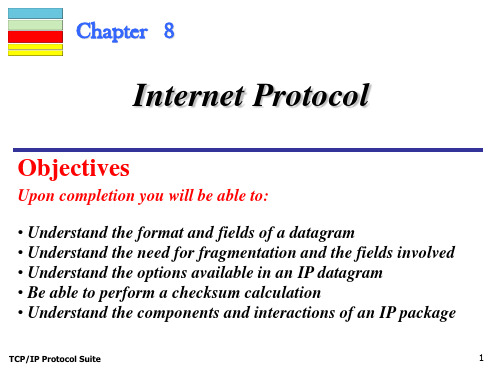
Chapter 8 Internet Protocol (IP)
TCP/IP Protocol Suite
24
Example 6
A packet has arrived with an M bit value of 1. Is this the first fragment, the last fragment, or a middle fragment? Do we know if the packet was fragmented?
22
Figure 8.9
Detailed fragmentation example
TCP/IP Protocol Suite
23
Example 5
A packet has arrived with an M bit value of 0. Is this the first fragment, the last fragment, or a middle fragment? Do we know if the packet was fragmented?
Solutionotal number of bytes in the header is 5 × 4 or 20 bytes (no options). The total length is 40 bytes, which means the packet is carrying 20 bytes of data (40 − 20).
Solution If the M bit is 0, it means that there are no more fragments; the fragment is the last one. However, we cannot say if the original packet was fragmented or not. A nonfragmented packet is considered the last fragment.
tcpip-chapter 5 delivery and routing of ip packets
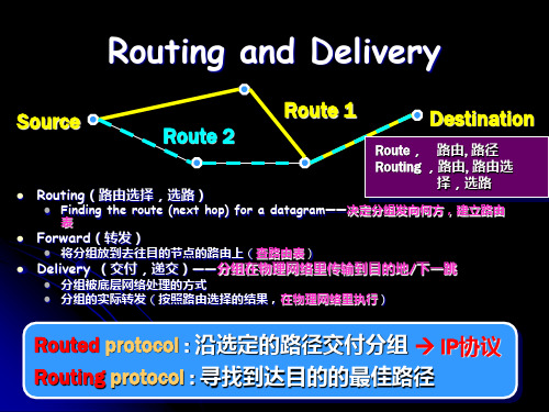
2nd delivery:indirect,Next-hop IP = IP21
3th delivery:direct, Dst IP = IPB 怎样确定
02.10.2020
下一跳?
8
交付的含义
查路由表决定分组的下一个接收者 交付——配合物理层完成传输——地址映射
(找到IP地址对应的物理地址)
02.10.2020
5
Direct vs. Indirect Delivery • 是否需要经过路由器?
Direct delivery(直接交付) • 配合物理网络传输
分组最终目的站点与分组的交付者(发送接口)在同 一个IP网络中 将分组直接投递给目的站点
更准确:二者在逻辑上属于同一个IP网络,物理上属于同一 个物理网络
主机
直接交付:将分组交付给目的站点 间接交付:将分组交付给给默认网关(Next hop)
路由器(多条Internet连接)
直接交付:将分组交付给目的站点(从哪一个接口送出?) 间接交付:交付给下一跳路由器(从哪一个接口送出?)
交付实质上反应了路由选择的结果
A
B
Net 1
02.10.2020
尽最大努力交付,best-effort delivery
02.10.2020
4
Chapter 5 Delivery, Forwarding, and Routing of IP Packets(IP分组交、转
发和路由选择)
Connection Delivery Routing methods (Forwarding) Static vs. dynamic routing Routing table and routing module Classless addressing: CIDR
网络管理PPT chapter4 网络管理原理-组织模型

课程:网络管理原理与工程技术基础
ch4 网络管理基本原理
2
网络管理模型框架
网络管理 模型框架
组织模型
信息模型
通信模型
功能模型
OSI 网络管理模型
SNMP Model Similar with OSI Model
3
OSI Model
Organization Model
Information Model
• 可以被直接管理的网元 • 不能被管理的对象 •
•
组织模型 组织模型的类别
根据各组成之间的关系可以划分
(1)直接管理(两层管理结构)(Two-tier network management organization model) (2)管理者/代理网络管理模型 (3)超管理组织模型 MoM (Manager of Manager)
7
(1)直接管理(两层管理结构)
8
管理系统 管理进程 (manager) 管理操作(管理协议)
代理
不能 被管 的对 象
响应或通知 (管理协议)
被管对象
MIB数据库
(2)管理者/代理网络管理模型
管理系统 管理进程 (manager) 受管系统
9
管 执行 管理操作(管理协议) 理 代 通知 响应或通知 理 (管理协议) Agent
http服务器 网络设备 浏览器
Internet
网络管理系统常用实现结构 集中式(Centralized Network Management) ; 分布式(Distributed Network Management) 分层结构式(Hierarchical Network Management)
代 理
Chap-04

IP Addresses: Classful Addressing
Objectives
Upon completion you will be able to:
• Understand IPv4 addresses and classes • Identify the class of an IP address • Find the network address given an IP address • Understand masks and how to use them • Understand subnets and supernets
TCP/IP Protocol Suite
1
4.1 INTRODUCTION
The identifier used in the IP layer of the TCP/IP protocol suite to identify each device connected to the Internet is called the Internet address or IP address. An IP address is a 32-bit address that uniquely and universally defines the connection of a host or a router to the Internet. IP addresses are unique. They are unique in the sense that each address defines one, and only one, connection to the Internet. Two devices on the Internet can never have the same address.
川大软院计网选择题答案Chapter4(含答案)
CHAPTER 4: NETWORK LAYER1.Which of the following groups belongs to network layer protocol? _____D____A.IP, TCP and UDPB.ARP, IP, and UDPC.FTP, IMAP and IPD.ICMP, BGP, and RIP2.The 3-PDU is named as ____C_____A.messageB.packetC.datagramD.segment3.In a datagram network, the forwarding decision is based on the value of the____B field in the packet header.A.source addressB.destination addressbelD.None of the choices are4.HOL blocking happens on ____A_____A.input portB.output portC.switching fabricsD.all of above5.If no free buffers in router, the arriving packets will be: AA.droppedB.queuedC.returnedD.marked6.During normal IP packet forwarding at a router, which of the following packetfields are updated? ____C____A.Source IP addressB.Destination IP addressC.ChecksumD.Destination port number7.Which of the following IP address doesn’t belong to the 202.115.32.0/25 network?______D___A.202.115.32.1B.202.115.32.11C.202.115.32.120D.202.115.32.1298.You are given an IP network of 192.168.5.0 and told that you need to separatethis network into sub networks that can support a maximum of 30 hosts per subnet.This will help alleviate congestion on the network. What subnet mask can you use to create the subnets necessary to meet the given criteria? ___C______A.255.255.255.0B.255.255.255.128C.255.255.255.224D.255.255.255.2409.An IP datagram of 1500 bytes (20 byte of IP header plus 1480 bytes of IP payload)arrives at a router and must be forwarded to a link with an MTU of 500 bytes.Thus the router has to fragment the datagram. To the last fragment, the value of offset should be _____D____A.1440B.1000C.186D.18010.IP is a ____C_____ protocol.A.connection-oriented unreliableB.connection-oriented reliableC.connectionless unreliableD.connectionless reliable11.Which ICMP message type is the basis for the Traceroute utility?BA.Echo RequestB.TTL expiredC.Host UnreachableD.Fragment Reassembly Time Exceed12.Routers in the path are not allowed to _________________B__________.A.fragment the packet they receiveB.change source or destination addressC.decapsulate the packetD.All of the choices are correct13.____B_____ allows a site to use a set of private addresses for internalcommunication and a set of global Internet addresses for communication with the rest of the world.A.DHCPB.NATC.ICMPD.None of the choices are correct14.How many bits are there in IPv6 ? ______C___A.32B.64C.128D.25615.In CIDR notation, which of the following networks contains host 192.168.14.2?CA.192.168.10.0/22B.192.168.11.0/21C.192.168.12.0/23D.192.168.13.0/2416.What is the limited broadcast address corresponding to the node with thefollowing IP address: 131.15.46.59?DA.131.15.46.255B.131.15.255.255C.255.255.255.255D.None of the above17.In classful IP addressing, how many network bits does 125.140.128.16 have?AA.8B.16C.24D.3218.What is the broadcast IP address for 193.140.141.128 / 26 ?DA.193.140.141.128B.193.140.141.127C.255.255.255.63D.193.140.141.19119.What’s a network? From IP address perspective they can physically reach eachother without intervening router and the device interfaces with: CA.same IP addressB.same TCP port #C.same network part of IP addressD.same host part of IP address20.The Internet’s network layer has three major components, the first component isthe IP protocol, the second component is the routing protocol, the final component is____.DA.forwardingB.address translationC.checkD.ICMP21.IP addressing assigns an address to 223.10.198.250/29, the network address forthis network is____.A()A.223.10.198.248B.223.10.198.250C.223.10.198.0D.223.10.0.022.There are two 16-bit integers: 1110 0110 0110 0110, 1101 0101 0101 0101. Theirchecksum isA____.A.0100010001000011B.1011101110111100C.1111111111111111D.100000000000000023.The use of hierarchy in routing tables can __A______ the size of the routingtables.A.reduceB.increaseC.neither reduce nor increaseD.None of the choices are correct24.Which of the following protocol doesn’t belong to intra-AS routing protocol?_____B____A.RIPB.BGPC.OSPFD.IRAP25.Which of the following protocol belongs to intra-AS routing protocol?______A___A.RIPB.BGPC.DV (Distance Vector)D.LS (Link State)26.In OSPF network, a ____B_____ belongs to both an area and the backbone.A.internal routerB.area border routerC.boundary routerD.backbone router27._A___ is an inter-domain routing protocol using path vector routing.A.BGPB.RIPC.OSPFD.None of the choices are correct28.RIP uses the services of ___C____.A.TCPB.IPC.UDPD.None of the choices are correct29.The Routing Information Protocol (RIP) is an intra-domain routing based on_______A__ routing.A.distance vectorB.link stateC.path vectorD.all of the above30.Which of the following algorithm has the so called count-to-infinity problem?CA.Flooding algorithmB.Link-state algorithmC.Distance vector algorithmD.None of the above。
Chapter4电路定理
a
c
a
R1 Rab R2 i3i3 R3
R5
+ ++
uS1 uab uS2
R4RRcd6
– ––
b
b
d
例2 求图示电路的等效发电机。
解:
iSc
40 20
40 40
60 20
3
1A
Req 20 // 40 // 20
1
1 1
1
8
20 40 20
20Ω
40Ω
20Ω 3A
+
25V
20
U
-
-
用结点电压法
o
1'
uao
1 5
1 20
1 4
25 5
3
U 4
uao
16
U 2
由 I uao U
4
U 32 8I
+ 8 I +1
4A
32V
-
U
-
1'
I +1
8 U
-
1'
i
ia
a +
Req
+
uoc=Reqisc
Nu
+
-b
uoc
-
u isc -
3.定理的应用
(1)开路电压uoc和短路电流iSc的计算
戴维宁等效电路中电压源电压等于将外电路断开时的开 路电压uoc,电压源方向与所求开路电压方向有关。诺顿等效 电路中电流源电流等于将外电路短路时的短路电流iSc,电流源 方向与所求短路电流的方向有关。计算uoc、 iSc的方法视电路 形式选择前面学过的任意方法,使易于计算。
IP地址与域名(课件)
域名的结构
总结词
域名由多个部分组成,包括顶级域名、二级域名、三级域名等。
详细描述
域名通常由多个部分组成,最顶层的是顶级域名(TLD),如.com、.org、.net 等。在顶级域名之下是二级域名,表示组织或个人的名称。在二级域名之下还可 以有三级域名,用于进一步区分不同的子组织或服务。
域名的解析
05
IP地址与域名的应用实例
Chapter
企业网站的IP地址与域名配置
总结词
企业网站是展示企业形象、宣传产品和服务的重要平台,IP地址与域名的配置对于企业 网站的稳定运行和推广至关重要。
详细描述
企业网站需要拥有独立的IP地址和域名,以便在互联网上建立稳定的访问链接。IP地址 是网站的唯一标识,而域名则是用户通过输入网址来访问网站的入口。企业网站需要将 域名解析到对应的IP地址,以便用户能够通过输入域名来访问网站。同时,企业网站还
C类
192.x.x.x - 223.x.x.x (192.0.0.0 223.255.255.0),范围是 192.0.0.1-223.255.255.255,用 于小型网络。
IPv6
由8组4位16进制数组成,由冒号( :)分隔。例如:FE80:。
IP地址的分配与回收
01
分配方式
静态分配和动态分配 。
IP地址劫持
攻击者通过技术手段篡改 路由信息,将流量劫持到 恶意服务器,窃取用户数 据或进行网络攻击。
域名的安全问题
域名劫持
黑客通过篡改DNS记录, 将域名解析到恶意服务器 ,窃取用户数据或进行网 络攻击。
域名滥用
利用域名进行欺诈、传播 恶意软件等不法活动,损 害用户利益和网络安全。
域名争议
运筹学 整数规划( Integer Programming )
检查所有分枝的解及目标函数值,若某分枝的解是整数并且目标函数 值大于(max)等于其它分枝的目标值,则将其它分枝剪去不再计算,若 还存在非整数解并且目标值大于(max)整数解的目标值,需要继续分枝, 再检查,直到得到最优解。
割平面法的内涵:
Page 18
通过找适当的割平面,使得切割后最终得到这样的可行域( 不一定一次性得到), 它的一个有整数坐标的顶点恰好是 问题的最优解.
-Gomory割平面法
例: 求解
max z x1 x2 s.t. x1 x2 1
3x1 x2 4 x1 , x2 0, 整 数
1 x1 3/4 1 0 -1/4 1/4 0
1 x2 7/4 0 1 3/4 1/4 0
0 x5 -3 0 0 -3 -1 1
0 0 -1/2 -1/2 0
由对偶单纯形法, x5为换出变量, x3为换入变量, 得Page 29
cj CB XB b 1 x1 1 1 x2 1 0 x3 1
1 100 0 x1 x2 x3 x4 x5 1 0 0 1/3 1/12 0 1 0 0 1/4 0 0 1 -1 -1/3 0 0 0 -1/2 -1/6
收敛性很慢. 但若下其它方法(如分枝定界法)配合使用,
也是有效的.
分支定界法
Page 33
分支定界法的解题步骤:
1)求整数规划的松弛问题最优解; 若松弛问题的最优解满足整数要求,得到整数规划的最优解,否则转下
一步; 2)分支与定界:
任意选一个非整数解的变量xi,在松弛问题中加上约束: xi≤[xi] 和 xi≥[xi]+1
- 1、下载文档前请自行甄别文档内容的完整性,平台不提供额外的编辑、内容补充、找答案等附加服务。
- 2、"仅部分预览"的文档,不可在线预览部分如存在完整性等问题,可反馈申请退款(可完整预览的文档不适用该条件!)。
- 3、如文档侵犯您的权益,请联系客服反馈,我们会尽快为您处理(人工客服工作时间:9:00-18:30)。
下一代互联网互联设备国家工程实验室
National Engineering Laboratory for Next Generation Internet Interconnection Devices
Area 0
RG
Virtual Links
Connects a new subarea to the backbone when a physical connection is impossible. Connect two physically separated backbones
Link State Database (Topology Map)
Contains all links (networks) in the area and their states. A complete collection of raw data.
Forwarding Database (Route Table)
2
Introduction to OSPFv2
OSPF is an Interior Gateway Protocol (IGP) based on link-
state routing algorithm designed for large IP networks.
Only for IP networks. Does not support non-IP networks. OSPF messages are encapsulated in IP. Protocol number: 89
Delay
The time it takes for a router to process, queue, and transmit a datagram out an interface. 下一代互联网互联设备国家工程实验室
National Engineering Laboratory for Next Generation Internet Interconnection Devices
8
OSPF Metrics Types
Support multiple metrics used to determine the best path to the destinations when multiple paths exist.
Bandwidth, reliability, load, delay.
Bandwidth (in default)
The transfer capacity of a link.
Reliability
The stability of the link in terms of lost datagrams.
Load(or Traffic)
A variable value that changes based on the utilization of the link.
Complexity: O(n2)
Area 1
RD
RH
Area 2
下一代互联网互联设备国家工程实验室
National Engineering Laboratory for Next Generation Internet Interconnection Devices
5
Area Types
Backbone area – Area 0
RFC 1247 RFC 1583 RFC2178 RFC2328 – OSPF version 2 (OSPFv2)
RFC2740 RFC5340- OSPF version 3 for IPv6 (OSPFv3)
下一代互联网互联设备国家工程实验室
National Engineering Laboratory for Next Generation Internet Interconnection Devices
The glue for all other areas. Be responsible for distributing routing information between non-backbone areas. Must be contiguous. Need not be physically contiguous, except virtual links.
9
Example for OSPF metric in bandwidth
Cisco IOS formula for OSPF metric
108/Bandwidth
下一代互联网互联设备国家工程实验室
National Engineering Laboratory for Next Generation Internet Interconnection Devices
Detect topological changes and converge on a new consensus of
the new topology very quickly.
BGP(179) TCP(6) RIP(520) UDP(17) IP OSPF(89)
下一代互联网互联设备国家工程实验室
Both the Designated Router and Backup Designated Router must be prepared to receive packets sent to this address.
下一代互联网互联设备国家工程实验室
National Engineering Laboratory for Next Generation Internet Interconnection Devices
Virtual link RB Area 0 RC Area 2 RF Virtual link
Area 1
Non-backbone area
RA
Area 5
RD Area 4 RK Area 3 RH
Must be connected to backbone area, RE except virtual links. All route update are exchanged between backbone area and non-backbone areas. No route exchange among non-backbone areas.
Chapter 4: Open Shortest Path First (OSPF)
The origins of OSPF
Fundamental limitations of distance-vector routing protocols
slow convergence, scalability problem, ……
下一代互联网互联设备国家工程实验室
National Engineering Laboratory for Next Generation Internet Interconnection Devices
4
OSPF Areas
Two goals of designing OSPF
Improved network scalability Rapid convergence
Link: connection between two routers. State: attribute of a link, like delay, bandwidth,……
The process of forwarding LSAs to all routers is known as known as flooding. When the network is converged, all routers in an area have the exact same link-state database. Each router runs Dijkstra algorithm to obtain the shortest path from the root to all destinations.
Area 0 Area 1
ABR Internal Backbone ASBR
RA
RB
RD
RC
External AS
下一代互联网互联设备国家工程实验室
National Engineering Laboratory for Next Generation Internet Interconnection Devices
10
OSPF Databases Types
Adjacency Database (Neighbor Table)
Contains the list of all known routing neighbors and various information regarding the neighbors.
Series of vendor-specific, Shortest Path First(SPF) routing protocols----link state algorithm(Dijkstra) IETF Open Shortest Path First (OSPF)
RFC 1131 – OSPF version 1(OSPFv1)
National Engineering Laboratory for Next Generation Internet Interconnection Devices
3
How OSPF Works
OSPF initializes by first building neighbor relationships with routers locally connected to. stored in the link-state database (LSDB).