手持读写器-AS3991
UHFRFID系统读写器射频收发模块硬件设计综述_李鸿

RIID硬件原理及其实现

组合模式
Registers 12, 14, 15, 16, and 17 are three bytes deep. They can be accessed by Continuous address mode only. The least significant byte is accessed first. It is possible to access only deep register in a single communication stream。
Continuous address mode
Cont mode=1, the first data that follows the address is written (or read) to (from) the given address. For each additional data, the address is incremented by one.
Start = start condition Adr = address with Cont bit low Adrc = address with the Cont bit high Cmd = command byte Data = data byte StopSgl = stop condition for termination of the command or non-continuous address mode StopCont = stop condition for termination of the continuous address mode
AS3992:UHF RFID读卡器

预 失真 功 能 和 . 6 B 的 接 8d m
收器 灵敏 度 。这意 味着 采 用
A 39 S 9 2的单一设计 系统 可交付给全球任何市场 。
一
优化 ,适 合 自我 供 电和
总线 供 电 US B,以及其 他 3 - V的热插拔应用 。 V5
AP21 01及 AP 1 21 1
Do e id s针 对 高 电 流 应 用 推 出 两 款 新 器 件 以扩 展 旗
下 A 2X P 1 X电 源 开 关产 品 线。 最新 的单 通 道 A 2 0 及 P 11 AP 1 1 提 供达 2 21 可 A的 连 续 输 出 电流 ,且 经过
产 品包括 了一 系 列先进 的 功 能, 如可编程 D RM滤波器 、
CN A系列 符合 严 格 IC 1 7 - E 6 31类 B级 震 动和 振动 3
I 0 1标准 。此 外 ,所 有型号都具有铁路 P LD / o C DC转 换器 的新 Ok mi I /. 0系列符 要求 ,以及 JS E 4 3 a . 3W4 OK T 0 10 合 所有 标准 U / N I C 6 9 01安 全认 证 ,并 与 R HS6 应用常见 的宽范 围 DC输入 ,允许 在 6 V- 6 V问 的任一 LE / 0 5 . E o .
与 A 2X P 1 X系列 中的 其它 产 品 一样 ,这 些新 器 件 在
高电容负 载和短 路时可 为应用提 供全 面的保护解 决方案 。 AP 1 X器件还具备反 向电流隔离 、 2X 过流 、 过温及短路保护 ,
以及可控的上升时问和欠压锁定功能。 匿团圆
Di ode WH W. odes com s / di .
AS 9 2U FD读卡器与现有 的 “ i l Ge ” 3 9 HFR I Smp n2 y
基于AS3992的超高频RFID读写器硬件设计
第1 3 卷第 2 期
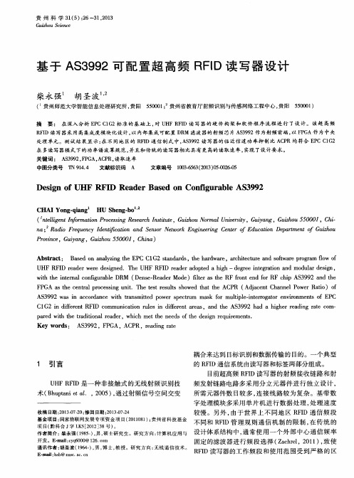
信号转 换 为单端 信号 , 进行 必要 阻抗 匹配 设计 , 然 后
通过 环形器 将射 频信 号发送 天线 。
电源 电路 : 输人电源为直流 9 V, 采 用 线 性 稳 压
器产 生三 组 电源 : 线性 5 V提 供 给 A S 3 9 9 2的 电源 引 脚端 V E X T 、 V E X T 2 , 输人 为 V E X T时 , 输 出为 V D D —
道 。读 写器 内部 电路功 能框 图如 图 2所示 。 应 用软 件与 基带 电路之 间数据 交 换一 般 通过 外 扩接 口实 现 , 外 扩 接 口可 以 是 U S B 2 . 0 , R S 2 3 2 / 4 8 5
R F I D读 写 器通 过 天 线 发 送 出一 定 频 率 的射 频
案 。该 读 写 器工 作 频 率 的 范 围为 8 6 0 MH z 一 9 6 0 MH z可调 , 符合 I S O 1 8 0 0 0— 6 C的 主 流 标 准 , 能 完成 符 合 E P C G e n 2标 准
的 电子标签的所有读写及控制操作 。 关键词 : 超 高频射频 识别; 读写 器; 硬件 架构; 射频 电路 ; 基 带电路
认证 。
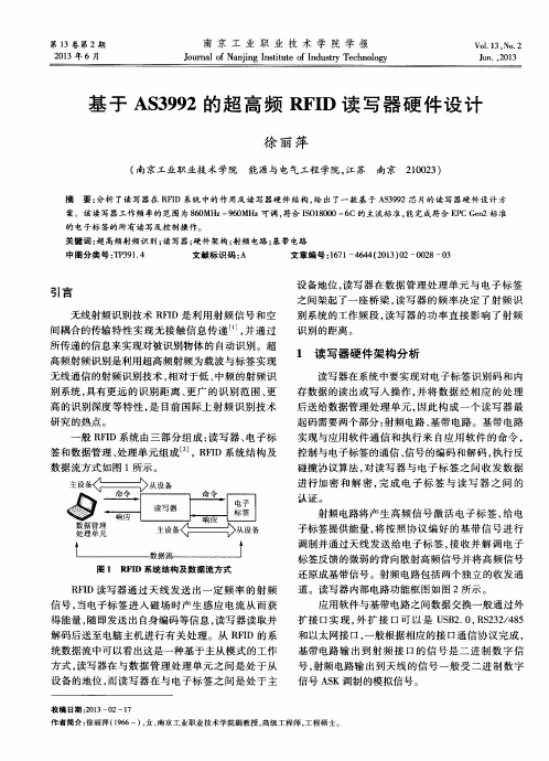
般R F I D系统 由三部 分 组 成 : 读写器、 电子标
签和数 据管 理 、 处理 单元 组 成 _ 2 J ,R F I D系统 结 构及
数据 流方式 如 图 1 所示。
射频 电路将 产 生 高 频 信 号 激 活 电 子标 签 , 给 电
子标 签 提供能 量 , 将 按 照协 议 编 好 的基 带 信 号 进 行
Vo 1 .1 3. No. 2
DS13890 Rev 1 ST25R3920B 汽车级NFC读卡器 数据手册说明书

这是关于全面投产产品的信息。
2022年9月DS13890 Rev 1 [English Rev 2]1/158ST25R3920B用于CCC 数字钥匙和汽车中控台的汽车级NFC 读卡器数据手册 - 生产数据特性•AEC-Q100认证•工作模式–读卡器/写卡器–卡模拟–有源和无源点对点•RF 通信–符合EMVCo ® 3.1a 模拟和数字标准–NFC-A / ISO14443A ,高达848 kbit/s –NFC-B / ISO14443B ,高达848 kbit/s –NFC-F / Felica™,高达424 kbit/s –NFC-V / ISO15693,高达53 kb/s–NFC-A / ISO14443A (106 kbit/s )和NFC-F / FeliCa™(212/424 kbit/s )卡模拟–有源和无源点对点发起方和目标模式,高达424 kbit/s –低级模式实现了兼容MIFARE Classic ®或其他自定义协议•主要特性–动态功率输出(DPO )控制场强度,以保持在给定限制内–主动波束成形(AWS )减少过冲和下冲–噪声抑制接收器(NSR )可在噪声环境中进行接收–通过可变电容进行自动天线调谐(AAT )–集成兼容EMVCo ® 3.1a 的EMD 处理–自动增益控制和静噪功能,可最大化信噪比–低功耗NFC 主动和被动目标模式–可调ASK 调制深度,从0到82% –集成稳压器,以提升系统PSRR–AM/PM 和I/Q 解调器,提供基带通道总和或自动通道选择功能–可驱动两根独立的单端天线–测量天线电压振幅和相位、RSSI 、片上电源和稳压值•外部通信接口–512字节FIFO–串行外设接口(SPI ),高达5 Mbit/s –I2C ,高达400 kbit/s (快速模式下),1 Mbit/s (极速模式下)及3.4 Mbit/s (高速模式下)•电气特性–宽电源电压和环境温度范围(-40°C 至+105°C 为2.6至5.5 V ,-20°C 至+105°C 为2.4至5.5 V )–宽外设通信电源范围,从1.65到5.5 V–石英振荡器,使用27.12 MHz 晶振,可快速启动目录ST25R3920B 目录1应用 . . . . . . . . . . . . . . . . . . . . . . . . . . . . . . . . . . . . . . . . . . . . . . . . . . . . . . 112说明 . . . . . . . . . . . . . . . . . . . . . . . . . . . . . . . . . . . . . . . . . . . . . . . . . . . . . . 122.1系统图 . . . . . . . . . . . . . . . . . . . . . . . . . . . . . . . . . . . . . . . . . . . . . . . . . . . . 132.2框图 . . . . . . . . . . . . . . . . . . . . . . . . . . . . . . . . . . . . . . . . . . . . . . . . . . . . . 152.2.1发送器 . . . . . . . . . . . . . . . . . . . . . . . . . . . . . . . . . . . . . . . . . . . . . . . . . . 152.2.2接收器 . . . . . . . . . . . . . . . . . . . . . . . . . . . . . . . . . . . . . . . . . . . . . . . . . . 162.2.3相位和幅度检测器 . . . . . . . . . . . . . . . . . . . . . . . . . . . . . . . . . . . . . . . . . 162.2.4自动天线调谐(AAT) . . . . . . . . . . . . . . . . . . . . . . . . . . . . . . . . . . . . . . . . 162.2.5A/D转换器 . . . . . . . . . . . . . . . . . . . . . . . . . . . . . . . . . . . . . . . . . . . . . . . 162.2.6外场检测器 . . . . . . . . . . . . . . . . . . . . . . . . . . . . . . . . . . . . . . . . . . . . . . . 162.2.7石英晶体振荡器 . . . . . . . . . . . . . . . . . . . . . . . . . . . . . . . . . . . . . . . . . . . 172.2.8电源稳压器 . . . . . . . . . . . . . . . . . . . . . . . . . . . . . . . . . . . . . . . . . . . . . . . 172.2.9上电复位和基准 . . . . . . . . . . . . . . . . . . . . . . . . . . . . . . . . . . . . . . . . . . . 172.2.10RC振荡器和唤醒定时器 . . . . . . . . . . . . . . . . . . . . . . . . . . . . . . . . . . . . . 172.2.11TX编码 . . . . . . . . . . . . . . . . . . . . . . . . . . . . . . . . . . . . . . . . . . . . . . . . . . 172.2.12RX 解码 . . . . . . . . . . . . . . . . . . . . . . . . . . . . . . . . . . . . . . . . . . . . . . . . . 172.2.13FIFO . . . . . . . . . . . . . . . . . . . . . . . . . . . . . . . . . . . . . . . . . . . . . . . . . . . . 182.2.14控制逻辑 . . . . . . . . . . . . . . . . . . . . . . . . . . . . . . . . . . . . . . . . . . . . . . . . 182.2.15主机接口 . . . . . . . . . . . . . . . . . . . . . . . . . . . . . . . . . . . . . . . . . . . . . . . . 182.2.16被动目标存储器 . . . . . . . . . . . . . . . . . . . . . . . . . . . . . . . . . . . . . . . . . . . 182.2.17P2RAM . . . . . . . . . . . . . . . . . . . . . . . . . . . . . . . . . . . . . . . . . . . . . . . . . 18 3引脚和信号说明 . . . . . . . . . . . . . . . . . . . . . . . . . . . . . . . . . . . . . . . . . . . . . 194应用信息 . . . . . . . . . . . . . . . . . . . . . . . . . . . . . . . . . . . . . . . . . . . . . . . . . . 214.1上电序列 . . . . . . . . . . . . . . . . . . . . . . . . . . . . . . . . . . . . . . . . . . . . . . . . . . 214.2工作模式 . . . . . . . . . . . . . . . . . . . . . . . . . . . . . . . . . . . . . . . . . . . . . . . . . . 214.2.1发送器 . . . . . . . . . . . . . . . . . . . . . . . . . . . . . . . . . . . . . . . . . . . . . . . . . . 224.2.2接收器 . . . . . . . . . . . . . . . . . . . . . . . . . . . . . . . . . . . . . . . . . . . . . . . . . . 234.2.3天线调谐 . . . . . . . . . . . . . . . . . . . . . . . . . . . . . . . . . . . . . . . . . . . . . . . . 284.2.4唤醒模式 . . . . . . . . . . . . . . . . . . . . . . . . . . . . . . . . . . . . . . . . . . . . . . . . 294.2.5石英晶体振荡器 . . . . . . . . . . . . . . . . . . . . . . . . . . . . . . . . . . . . . . . . . . . 304.2.6定时器 . . . . . . . . . . . . . . . . . . . . . . . . . . . . . . . . . . . . . . . . . . . . . . . . . . 30 2/158DS13890 Rev 1 [English Rev 2]ST25R3920B目录4.2.7A/D转换器 . . . . . . . . . . . . . . . . . . . . . . . . . . . . . . . . . . . . . . . . . . . . . . . 334.2.8相位和幅度检测器 . . . . . . . . . . . . . . . . . . . . . . . . . . . . . . . . . . . . . . . . . 334.2.9外场检测器 . . . . . . . . . . . . . . . . . . . . . . . . . . . . . . . . . . . . . . . . . . . . . . . 344.2.10电源供电系统 . . . . . . . . . . . . . . . . . . . . . . . . . . . . . . . . . . . . . . . . . . . . . 354.2.11过冲/下冲保护 . . . . . . . . . . . . . . . . . . . . . . . . . . . . . . . . . . . . . . . . . . . . 384.2.12主动波束成形 . . . . . . . . . . . . . . . . . . . . . . . . . . . . . . . . . . . . . . . . . . . . . 394.2.13读取操作 . . . . . . . . . . . . . . . . . . . . . . . . . . . . . . . . . . . . . . . . . . . . . . . . 434.2.14侦听模式 . . . . . . . . . . . . . . . . . . . . . . . . . . . . . . . . . . . . . . . . . . . . . . . . 444.3和外部微控制器的通信 . . . . . . . . . . . . . . . . . . . . . . . . . . . . . . . . . . . . . . . 474.3.1中断接口 . . . . . . . . . . . . . . . . . . . . . . . . . . . . . . . . . . . . . . . . . . . . . . . . 474.3.2通信接口选择 . . . . . . . . . . . . . . . . . . . . . . . . . . . . . . . . . . . . . . . . . . . . . 494.3.3串行外设接口 (SPI) . . . . . . . . . . . . . . . . . . . . . . . . . . . . . . . . . . . . . . . . 494.3.4I2C接口 . . . . . . . . . . . . . . . . . . . . . . . . . . . . . . . . . . . . . . . . . . . . . . . . . 544.4直接指令 . . . . . . . . . . . . . . . . . . . . . . . . . . . . . . . . . . . . . . . . . . . . . . . . . . 584.4.1设为默认 . . . . . . . . . . . . . . . . . . . . . . . . . . . . . . . . . . . . . . . . . . . . . . . . 604.4.2停止所有动作 . . . . . . . . . . . . . . . . . . . . . . . . . . . . . . . . . . . . . . . . . . . . . 604.4.3清除 FIFO . . . . . . . . . . . . . . . . . . . . . . . . . . . . . . . . . . . . . . . . . . . . . . . 604.4.4发送指令 . . . . . . . . . . . . . . . . . . . . . . . . . . . . . . . . . . . . . . . . . . . . . . . . 614.4.5NFC开场指令 . . . . . . . . . . . . . . . . . . . . . . . . . . . . . . . . . . . . . . . . . . . . . 614.4.6含掩码接收数据和不含掩码接收数据 . . . . . . . . . . . . . . . . . . . . . . . . . . . 634.4.7更改AM调制状态 . . . . . . . . . . . . . . . . . . . . . . . . . . . . . . . . . . . . . . . . . . 634.4.8幅度测量 . . . . . . . . . . . . . . . . . . . . . . . . . . . . . . . . . . . . . . . . . . . . . . . . 634.4.9接收增益复位 . . . . . . . . . . . . . . . . . . . . . . . . . . . . . . . . . . . . . . . . . . . . . 634.4.10调准器调整 . . . . . . . . . . . . . . . . . . . . . . . . . . . . . . . . . . . . . . . . . . . . . . . 634.4.11相位测量 . . . . . . . . . . . . . . . . . . . . . . . . . . . . . . . . . . . . . . . . . . . . . . . . 644.4.12清空接收信号强度指示 . . . . . . . . . . . . . . . . . . . . . . . . . . . . . . . . . . . . . . 644.4.13透传模式 . . . . . . . . . . . . . . . . . . . . . . . . . . . . . . . . . . . . . . . . . . . . . . . . 644.4.14供电电压测量 . . . . . . . . . . . . . . . . . . . . . . . . . . . . . . . . . . . . . . . . . . . . . 644.4.15触发RC校准 . . . . . . . . . . . . . . . . . . . . . . . . . . . . . . . . . . . . . . . . . . . . . . 644.4.16进入测试 . . . . . . . . . . . . . . . . . . . . . . . . . . . . . . . . . . . . . . . . . . . . . . . . 654.5寄存器 . . . . . . . . . . . . . . . . . . . . . . . . . . . . . . . . . . . . . . . . . . . . . . . . . . . . 664.5.1IO配置寄存器1 . . . . . . . . . . . . . . . . . . . . . . . . . . . . . . . . . . . . . . . . . . . . 704.5.2IO配置寄存器2 . . . . . . . . . . . . . . . . . . . . . . . . . . . . . . . . . . . . . . . . . . . . 714.5.3操作控制寄存器 . . . . . . . . . . . . . . . . . . . . . . . . . . . . . . . . . . . . . . . . . . . 724.5.4模式定义寄存器 . . . . . . . . . . . . . . . . . . . . . . . . . . . . . . . . . . . . . . . . . . . 734.5.5比特率定义寄存器 . . . . . . . . . . . . . . . . . . . . . . . . . . . . . . . . . . . . . . . . . 754.5.6ISO14443A和NFC 106kb/s设置寄存器 . . . . . . . . . . . . . . . . . . . . . . . . . 76DS13890 Rev 1 [English Rev 2]3/158目录ST25R3920B4.5.7ISO14443B设置寄存器1 . . . . . . . . . . . . . . . . . . . . . . . . . . . . . . . . . . . . 774.5.8ISO14443B和FeliCa设置寄存器 . . . . . . . . . . . . . . . . . . . . . . . . . . . . . . 784.5.9NFCIP-1被动目标定义寄存器 . . . . . . . . . . . . . . . . . . . . . . . . . . . . . . . . 794.5.10流模式定义寄存器 . . . . . . . . . . . . . . . . . . . . . . . . . . . . . . . . . . . . . . . . . 804.5.11辅助定义寄存器 . . . . . . . . . . . . . . . . . . . . . . . . . . . . . . . . . . . . . . . . . . . 814.5.12EMD抑制配置寄存器 . . . . . . . . . . . . . . . . . . . . . . . . . . . . . . . . . . . . . . . 824.5.13副载波启动计时器寄存器 . . . . . . . . . . . . . . . . . . . . . . . . . . . . . . . . . . . . 834.5.14接收器配置寄存器1 . . . . . . . . . . . . . . . . . . . . . . . . . . . . . . . . . . . . . . . . 844.5.15接收器配置寄存器2 . . . . . . . . . . . . . . . . . . . . . . . . . . . . . . . . . . . . . . . . 854.5.16接收器配置寄存器3 . . . . . . . . . . . . . . . . . . . . . . . . . . . . . . . . . . . . . . . . 864.5.17接收器配置寄存器4 . . . . . . . . . . . . . . . . . . . . . . . . . . . . . . . . . . . . . . . . 864.5.18P2P接收器配置寄存器1 . . . . . . . . . . . . . . . . . . . . . . . . . . . . . . . . . . . . . 874.5.19相关器配置寄存器1 . . . . . . . . . . . . . . . . . . . . . . . . . . . . . . . . . . . . . . . . 884.5.20相关器配置寄存器2 . . . . . . . . . . . . . . . . . . . . . . . . . . . . . . . . . . . . . . . . 894.5.21带掩码接收定时器寄存器 . . . . . . . . . . . . . . . . . . . . . . . . . . . . . . . . . . . . 904.5.22无响应定时器寄存器1 . . . . . . . . . . . . . . . . . . . . . . . . . . . . . . . . . . . . . . 914.5.23无响应定时器寄存器2 . . . . . . . . . . . . . . . . . . . . . . . . . . . . . . . . . . . . . . 914.5.24定时器和EMV控制寄存器 . . . . . . . . . . . . . . . . . . . . . . . . . . . . . . . . . . . . 924.5.25通用定时器寄存器1 . . . . . . . . . . . . . . . . . . . . . . . . . . . . . . . . . . . . . . . . 934.5.26通用定时器寄存器2 . . . . . . . . . . . . . . . . . . . . . . . . . . . . . . . . . . . . . . . . 934.5.27PPON2场等待寄存器 . . . . . . . . . . . . . . . . . . . . . . . . . . . . . . . . . . . . . . . 944.5.28静噪定时器寄存器 . . . . . . . . . . . . . . . . . . . . . . . . . . . . . . . . . . . . . . . . . 954.5.29NFC开场保护定时器寄存器. . . . . . . . . . . . . . . . . . . . . . . . . . . . . . . . . . 954.5.30含掩码的主中断寄存器 . . . . . . . . . . . . . . . . . . . . . . . . . . . . . . . . . . . . . . 964.5.31含掩码的定时器和 NFC 中断寄存器 . . . . . . . . . . . . . . . . . . . . . . . . . . . 964.5.32含掩码的错误和唤醒中断寄存器 . . . . . . . . . . . . . . . . . . . . . . . . . . . . . . 974.5.33含掩码的被动目标中断寄存器 . . . . . . . . . . . . . . . . . . . . . . . . . . . . . . . . 974.5.34主中断寄存器 . . . . . . . . . . . . . . . . . . . . . . . . . . . . . . . . . . . . . . . . . . . . . 984.5.35定时器和NFC中断寄存器 . . . . . . . . . . . . . . . . . . . . . . . . . . . . . . . . . . . . 994.5.36错误和唤醒中断寄存器 . . . . . . . . . . . . . . . . . . . . . . . . . . . . . . . . . . . . . 1004.5.37被动目标中断寄存器 . . . . . . . . . . . . . . . . . . . . . . . . . . . . . . . . . . . . . . 1014.5.38FIFO状态寄存器1 . . . . . . . . . . . . . . . . . . . . . . . . . . . . . . . . . . . . . . . . . 1024.5.39FIFO状态寄存器2 . . . . . . . . . . . . . . . . . . . . . . . . . . . . . . . . . . . . . . . . . 1024.5.40冲突显示寄存器 . . . . . . . . . . . . . . . . . . . . . . . . . . . . . . . . . . . . . . . . . . 1034.5.41被动目标显示寄存器 . . . . . . . . . . . . . . . . . . . . . . . . . . . . . . . . . . . . . . 1044.5.42发送字节数寄存器1 . . . . . . . . . . . . . . . . . . . . . . . . . . . . . . . . . . . . . . . 1054.5.43发送字节数寄存器2 . . . . . . . . . . . . . . . . . . . . . . . . . . . . . . . . . . . . . . . 105 4/158DS13890 Rev 1 [English Rev 2]ST25R3920B目录4.5.44比特率检测显示寄存器 . . . . . . . . . . . . . . . . . . . . . . . . . . . . . . . . . . . . . 1064.5.45A/D转换器输出寄存器 . . . . . . . . . . . . . . . . . . . . . . . . . . . . . . . . . . . . . 1074.5.46天线调谐控制寄存器 1 . . . . . . . . . . . . . . . . . . . . . . . . . . . . . . . . . . . . . 1084.5.47天线调谐控制寄存器 2 . . . . . . . . . . . . . . . . . . . . . . . . . . . . . . . . . . . . . 1084.5.48TX驱动器寄存器 . . . . . . . . . . . . . . . . . . . . . . . . . . . . . . . . . . . . . . . . . . 1094.5.49辅助调制设置寄存器 . . . . . . . . . . . . . . . . . . . . . . . . . . . . . . . . . . . . . . 1114.5.50被动目标调制寄存器 . . . . . . . . . . . . . . . . . . . . . . . . . . . . . . . . . . . . . . 1124.5.51TX驱动器时序寄存器. . . . . . . . . . . . . . . . . . . . . . . . . . . . . . . . . . . . . . 1134.5.52外场检测器激活阈值寄存器 . . . . . . . . . . . . . . . . . . . . . . . . . . . . . . . . . 1144.5.53AM调制寄存器. . . . . . . . . . . . . . . . . . . . . . . . . . . . . . . . . . . . . . . . . . . 1154.5.54外场检测器取消激活阈值寄存器 . . . . . . . . . . . . . . . . . . . . . . . . . . . . . 1174.5.55TX驱动器时序显示寄存器 . . . . . . . . . . . . . . . . . . . . . . . . . . . . . . . . . . 1194.5.56稳压器电压控制寄存器 . . . . . . . . . . . . . . . . . . . . . . . . . . . . . . . . . . . . . 1204.5.57稳压器显示寄存器 . . . . . . . . . . . . . . . . . . . . . . . . . . . . . . . . . . . . . . . . 1214.5.58RSSI显示寄存器 . . . . . . . . . . . . . . . . . . . . . . . . . . . . . . . . . . . . . . . . . 1224.5.59增益减少状态寄存器 . . . . . . . . . . . . . . . . . . . . . . . . . . . . . . . . . . . . . . 1234.5.60AWS配置1寄存器 . . . . . . . . . . . . . . . . . . . . . . . . . . . . . . . . . . . . . . . . . 1244.5.61AWS配置2寄存器 . . . . . . . . . . . . . . . . . . . . . . . . . . . . . . . . . . . . . . . . . 1254.5.62辅助显示寄存器 . . . . . . . . . . . . . . . . . . . . . . . . . . . . . . . . . . . . . . . . . . 1264.5.63过冲保护配置寄存器1 . . . . . . . . . . . . . . . . . . . . . . . . . . . . . . . . . . . . . 1274.5.64过冲保护配置寄存器2 . . . . . . . . . . . . . . . . . . . . . . . . . . . . . . . . . . . . . 1274.5.65下冲保护配置寄存器1 . . . . . . . . . . . . . . . . . . . . . . . . . . . . . . . . . . . . . 1284.5.66下冲保护配置寄存器2 . . . . . . . . . . . . . . . . . . . . . . . . . . . . . . . . . . . . . 1294.5.67唤醒定时器控制寄存器 . . . . . . . . . . . . . . . . . . . . . . . . . . . . . . . . . . . . . 1304.5.68幅度测量配置寄存器 . . . . . . . . . . . . . . . . . . . . . . . . . . . . . . . . . . . . . . 1314.5.69幅度测量参考寄存器 . . . . . . . . . . . . . . . . . . . . . . . . . . . . . . . . . . . . . . 1314.5.70AWS时间1寄存器 . . . . . . . . . . . . . . . . . . . . . . . . . . . . . . . . . . . . . . . . . 1324.5.71AWS时间2寄存器 . . . . . . . . . . . . . . . . . . . . . . . . . . . . . . . . . . . . . . . . . 1324.5.72AWS时间3寄存器 . . . . . . . . . . . . . . . . . . . . . . . . . . . . . . . . . . . . . . . . . 1334.5.73AWS时间4寄存器 . . . . . . . . . . . . . . . . . . . . . . . . . . . . . . . . . . . . . . . . . 1334.5.74AWS时间5寄存器 . . . . . . . . . . . . . . . . . . . . . . . . . . . . . . . . . . . . . . . . . 1344.5.75AWS时间6寄存器 . . . . . . . . . . . . . . . . . . . . . . . . . . . . . . . . . . . . . . . . . 1344.5.76幅度测量自动取平均显示寄存器 . . . . . . . . . . . . . . . . . . . . . . . . . . . . . 1354.5.77幅度测量显示寄存器 . . . . . . . . . . . . . . . . . . . . . . . . . . . . . . . . . . . . . . 1354.5.78相位测量配置寄存器 . . . . . . . . . . . . . . . . . . . . . . . . . . . . . . . . . . . . . . 1364.5.79相位测量参考寄存器 . . . . . . . . . . . . . . . . . . . . . . . . . . . . . . . . . . . . . . 1364.5.80相位测量自动取平均显示寄存器 . . . . . . . . . . . . . . . . . . . . . . . . . . . . . 137DS13890 Rev 1 [English Rev 2]5/158目录ST25R3920B4.5.81相位测量显示寄存器 . . . . . . . . . . . . . . . . . . . . . . . . . . . . . . . . . . . . . . 1374.5.82测量TX延迟 . . . . . . . . . . . . . . . . . . . . . . . . . . . . . . . . . . . . . . . . . . . . . 1384.5.83芯片ID寄存器 . . . . . . . . . . . . . . . . . . . . . . . . . . . . . . . . . . . . . . . . . . . . 1405电气特性 . . . . . . . . . . . . . . . . . . . . . . . . . . . . . . . . . . . . . . . . . . . . . . . . . 1415.1绝对最大额定值 . . . . . . . . . . . . . . . . . . . . . . . . . . . . . . . . . . . . . . . . . . . 1415.2工作条件 . . . . . . . . . . . . . . . . . . . . . . . . . . . . . . . . . . . . . . . . . . . . . . . . . 1425.3数字输入和输出的DC/AC特性 . . . . . . . . . . . . . . . . . . . . . . . . . . . . . . . . 1435.4电气特性 . . . . . . . . . . . . . . . . . . . . . . . . . . . . . . . . . . . . . . . . . . . . . . . . . 1445.5SPI 接口特性 . . . . . . . . . . . . . . . . . . . . . . . . . . . . . . . . . . . . . . . . . . . . . 1475.6I2C 接口特性 . . . . . . . . . . . . . . . . . . . . . . . . . . . . . . . . . . . . . . . . . . . . . 1496封装信息 . . . . . . . . . . . . . . . . . . . . . . . . . . . . . . . . . . . . . . . . . . . . . . . . . 1546.1VFQFPN32封装信息 . . . . . . . . . . . . . . . . . . . . . . . . . . . . . . . . . . . . . . . 154 7订购信息 . . . . . . . . . . . . . . . . . . . . . . . . . . . . . . . . . . . . . . . . . . . . . . . . . 156 8版本历史 . . . . . . . . . . . . . . . . . . . . . . . . . . . . . . . . . . . . . . . . . . . . . . . . . 1576/158DS13890 Rev 1 [English Rev 2]ST25R3920B表格索引表格索引表1.ST25R3920BVFQFPN32 引脚分配 . . . . . . . . . . . . . . . . . . . . . . . . . . . . . . . . . . . . . . . . . . 19表2.RX通道选择 . . . . . . . . . . . . . . . . . . . . . . . . . . . . . . . . . . . . . . . . . . . . . . . . . . . . . . . . . . . . 24表3.低通控制. . . . . . . . . . . . . . . . . . . . . . . . . . . . . . . . . . . . . . . . . . . . . . . . . . . . . . . . . . . . . . . 25表4.第一级和第三级零点设置 . . . . . . . . . . . . . . . . . . . . . . . . . . . . . . . . . . . . . . . . . . . . . . . . . . 26表5.用于OOK和ASK 模式下的低速、中速和快速传输的典型预设值. . . . . . . . . . . . . . . . . . . . . 40表6.PT_Memory地址空间 . . . . . . . . . . . . . . . . . . . . . . . . . . . . . . . . . . . . . . . . . . . . . . . . . . . . . 45表7.NFC-212/424k SENS_RES格式. . . . . . . . . . . . . . . . . . . . . . . . . . . . . . . . . . . . . . . . . . . . . 46表8.IRQ输出 . . . . . . . . . . . . . . . . . . . . . . . . . . . . . . . . . . . . . . . . . . . . . . . . . . . . . . . . . . . . . . . 47表9.串行数据接口(4线接口)信号线 . . . . . . . . . . . . . . . . . . . . . . . . . . . . . . . . . . . . . . . . . . . . 49表10.SPI工作模式 . . . . . . . . . . . . . . . . . . . . . . . . . . . . . . . . . . . . . . . . . . . . . . . . . . . . . . . . . . . . 50表11.I2C接口和中断信号线. . . . . . . . . . . . . . . . . . . . . . . . . . . . . . . . . . . . . . . . . . . . . . . . . . . . . 55表12.直接指令列表 . . . . . . . . . . . . . . . . . . . . . . . . . . . . . . . . . . . . . . . . . . . . . . . . . . . . . . . . . . . 58表13.NFC 开场指令的时序参数. . . . . . . . . . . . . . . . . . . . . . . . . . . . . . . . . . . . . . . . . . . . . . . . . . 62表14.模拟测试和查看寄存器1 . . . . . . . . . . . . . . . . . . . . . . . . . . . . . . . . . . . . . . . . . . . . . . . . . . . 65表15.T测试通道寄存器 - TAD1 和TAD2 管脚信号选择 . . . . . . . . . . . . . . . . . . . . . . . . . . . . . . . . 65表16.寄存器列表 - 空间A. . . . . . . . . . . . . . . . . . . . . . . . . . . . . . . . . . . . . . . . . . . . . . . . . . . . . . . 66表17.寄存器列表 - 空间B. . . . . . . . . . . . . . . . . . . . . . . . . . . . . . . . . . . . . . . . . . . . . . . . . . . . . . . 68表18.IO配置寄存器1 . . . . . . . . . . . . . . . . . . . . . . . . . . . . . . . . . . . . . . . . . . . . . . . . . . . . . . . . . . 70表19.IO配置寄存器2 . . . . . . . . . . . . . . . . . . . . . . . . . . . . . . . . . . . . . . . . . . . . . . . . . . . . . . . . . . 71表20.操作控制寄存器. . . . . . . . . . . . . . . . . . . . . . . . . . . . . . . . . . . . . . . . . . . . . . . . . . . . . . . . . . 72表21.模式定义寄存器. . . . . . . . . . . . . . . . . . . . . . . . . . . . . . . . . . . . . . . . . . . . . . . . . . . . . . . . . . 73表22.初始化操作模式. . . . . . . . . . . . . . . . . . . . . . . . . . . . . . . . . . . . . . . . . . . . . . . . . . . . . . . . . . 73表23.目标工作模式 . . . . . . . . . . . . . . . . . . . . . . . . . . . . . . . . . . . . . . . . . . . . . . . . . . . . . . . . . . . 73表24.比特率定义寄存器. . . . . . . . . . . . . . . . . . . . . . . . . . . . . . . . . . . . . . . . . . . . . . . . . . . . . . . . 75表25.比特率编码 . . . . . . . . . . . . . . . . . . . . . . . . . . . . . . . . . . . . . . . . . . . . . . . . . . . . . . . . . . . . . 75表26.ISO14443A和NFC 106kb/s设置寄存器. . . . . . . . . . . . . . . . . . . . . . . . . . . . . . . . . . . . . . . . 76表27.调制脉冲宽度 . . . . . . . . . . . . . . . . . . . . . . . . . . . . . . . . . . . . . . . . . . . . . . . . . . . . . . . . . . . 76表28.ISO14443B设置寄存器1. . . . . . . . . . . . . . . . . . . . . . . . . . . . . . . . . . . . . . . . . . . . . . . . . . . 77表29.ISO14443B和FeliCa设置寄存器. . . . . . . . . . . . . . . . . . . . . . . . . . . . . . . . . . . . . . . . . . . . . 78表30.最小TR1编码. . . . . . . . . . . . . . . . . . . . . . . . . . . . . . . . . . . . . . . . . . . . . . . . . . . . . . . . . . . . 78表31.NFCIP-1被动目标定义寄存器 . . . . . . . . . . . . . . . . . . . . . . . . . . . . . . . . . . . . . . . . . . . . . . . 79表32.流模式定义寄存器. . . . . . . . . . . . . . . . . . . . . . . . . . . . . . . . . . . . . . . . . . . . . . . . . . . . . . . . 80表33.副载波流模式的副载波频率定义 . . . . . . . . . . . . . . . . . . . . . . . . . . . . . . . . . . . . . . . . . . . . . 80表34.流模式Tx调制器控制的时间周期定义 . . . . . . . . . . . . . . . . . . . . . . . . . . . . . . . . . . . . . . . . . 80表35.辅助定义寄存器. . . . . . . . . . . . . . . . . . . . . . . . . . . . . . . . . . . . . . . . . . . . . . . . . . . . . . . . . . 81表36.EMD抑制配置寄存器. . . . . . . . . . . . . . . . . . . . . . . . . . . . . . . . . . . . . . . . . . . . . . . . . . . . . . 82表37.副载波启动计时器寄存器 . . . . . . . . . . . . . . . . . . . . . . . . . . . . . . . . . . . . . . . . . . . . . . . . . . 83表38.接收器配置寄存器1. . . . . . . . . . . . . . . . . . . . . . . . . . . . . . . . . . . . . . . . . . . . . . . . . . . . . . . 84表39.接收器配置寄存器2. . . . . . . . . . . . . . . . . . . . . . . . . . . . . . . . . . . . . . . . . . . . . . . . . . . . . . . 85表40.接收器配置寄存器3. . . . . . . . . . . . . . . . . . . . . . . . . . . . . . . . . . . . . . . . . . . . . . . . . . . . . . . 86表41.接收器配置寄存器4. . . . . . . . . . . . . . . . . . . . . . . . . . . . . . . . . . . . . . . . . . . . . . . . . . . . . . . 86表42.P2P接收器配置寄存器1 . . . . . . . . . . . . . . . . . . . . . . . . . . . . . . . . . . . . . . . . . . . . . . . . . . . 87表43.OOK阈值设置. . . . . . . . . . . . . . . . . . . . . . . . . . . . . . . . . . . . . . . . . . . . . . . . . . . . . . . . . . . 87表44.相关器配置寄存器1. . . . . . . . . . . . . . . . . . . . . . . . . . . . . . . . . . . . . . . . . . . . . . . . . . . . . . . 88表45.相关器配置寄存器2. . . . . . . . . . . . . . . . . . . . . . . . . . . . . . . . . . . . . . . . . . . . . . . . . . . . . . . 89表46.含掩码接收定时器寄存器 . . . . . . . . . . . . . . . . . . . . . . . . . . . . . . . . . . . . . . . . . . . . . . . . . . 90表47.无响应定时器寄存器1. . . . . . . . . . . . . . . . . . . . . . . . . . . . . . . . . . . . . . . . . . . . . . . . . . . . . 91表48.无响应定时器寄存器2. . . . . . . . . . . . . . . . . . . . . . . . . . . . . . . . . . . . . . . . . . . . . . . . . . . . . 91DS13890 Rev 1 [English Rev 2]7/158表格索引ST25R3920B 表49.定时器和EMV控制寄存器 . . . . . . . . . . . . . . . . . . . . . . . . . . . . . . . . . . . . . . . . . . . . . . . . . . 92表50.触发源. . . . . . . . . . . . . . . . . . . . . . . . . . . . . . . . . . . . . . . . . . . . . . . . . . . . . . . . . . . . . . . . . 92表51.通用定时器寄存器1. . . . . . . . . . . . . . . . . . . . . . . . . . . . . . . . . . . . . . . . . . . . . . . . . . . . . . . 93表52.通用定时器寄存器2. . . . . . . . . . . . . . . . . . . . . . . . . . . . . . . . . . . . . . . . . . . . . . . . . . . . . . . 93表53.PPON2场等待寄存器 . . . . . . . . . . . . . . . . . . . . . . . . . . . . . . . . . . . . . . . . . . . . . . . . . . . . . 94表54.静噪定时器寄存器. . . . . . . . . . . . . . . . . . . . . . . . . . . . . . . . . . . . . . . . . . . . . . . . . . . . . . . . 95表55.NFC 开场保护定时器寄存器 . . . . . . . . . . . . . . . . . . . . . . . . . . . . . . . . . . . . . . . . . . . . . . . . 95表56.掩码的主中断寄存器. . . . . . . . . . . . . . . . . . . . . . . . . . . . . . . . . . . . . . . . . . . . . . . . . . . . . . 96表57.掩码定时器和NFC 中断寄存器 . . . . . . . . . . . . . . . . . . . . . . . . . . . . . . . . . . . . . . . . . . . . . . 96表58.掩码错误和唤醒中断寄存器. . . . . . . . . . . . . . . . . . . . . . . . . . . . . . . . . . . . . . . . . . . . . . . . . 97表59.含掩码的被动目标中断寄存器. . . . . . . . . . . . . . . . . . . . . . . . . . . . . . . . . . . . . . . . . . . . . . . 97表60.主中断寄存器 . . . . . . . . . . . . . . . . . . . . . . . . . . . . . . . . . . . . . . . . . . . . . . . . . . . . . . . . . . . 98表61.定时器和NFC中断寄存器 . . . . . . . . . . . . . . . . . . . . . . . . . . . . . . . . . . . . . . . . . . . . . . . . . . 99表62.错误和唤醒中断寄存器 . . . . . . . . . . . . . . . . . . . . . . . . . . . . . . . . . . . . . . . . . . . . . . . . . . . 100表63.被动目标中断寄存器. . . . . . . . . . . . . . . . . . . . . . . . . . . . . . . . . . . . . . . . . . . . . . . . . . . . . 101表64.FIFO状态寄存器1 . . . . . . . . . . . . . . . . . . . . . . . . . . . . . . . . . . . . . . . . . . . . . . . . . . . . . . . 102表65.FIFO状态寄存器2 . . . . . . . . . . . . . . . . . . . . . . . . . . . . . . . . . . . . . . . . . . . . . . . . . . . . . . . 102表66.冲突显示寄存器. . . . . . . . . . . . . . . . . . . . . . . . . . . . . . . . . . . . . . . . . . . . . . . . . . . . . . . . . 103表67.被动目标显示寄存器. . . . . . . . . . . . . . . . . . . . . . . . . . . . . . . . . . . . . . . . . . . . . . . . . . . . . 104表68.发送字节数寄存器1. . . . . . . . . . . . . . . . . . . . . . . . . . . . . . . . . . . . . . . . . . . . . . . . . . . . . . 105表69.发送字节数寄存器2 . . . . . . . . . . . . . . . . . . . . . . . . . . . . . . . . . . . . . . . . . . . . . . . . . . . . . 105表70.比特率检测显示寄存器 . . . . . . . . . . . . . . . . . . . . . . . . . . . . . . . . . . . . . . . . . . . . . . . . . . . 106表71.A/D转换器输出寄存器. . . . . . . . . . . . . . . . . . . . . . . . . . . . . . . . . . . . . . . . . . . . . . . . . . . . 107表72.天线调谐控制寄存器1. . . . . . . . . . . . . . . . . . . . . . . . . . . . . . . . . . . . . . . . . . . . . . . . . . . . 108表73.天线调谐控制寄存器2. . . . . . . . . . . . . . . . . . . . . . . . . . . . . . . . . . . . . . . . . . . . . . . . . . . . 108表74.TX驱动器寄存器 . . . . . . . . . . . . . . . . . . . . . . . . . . . . . . . . . . . . . . . . . . . . . . . . . . . . . . . . 109表75.AM调制指数 . . . . . . . . . . . . . . . . . . . . . . . . . . . . . . . . . . . . . . . . . . . . . . . . . . . . . . . . . . . 109表76.RFO驱动阻抗 . . . . . . . . . . . . . . . . . . . . . . . . . . . . . . . . . . . . . . . . . . . . . . . . . . . . . . . . . . 110表77.辅助调制设置寄存器. . . . . . . . . . . . . . . . . . . . . . . . . . . . . . . . . . . . . . . . . . . . . . . . . . . . . 111表78.被动目标调制寄存器. . . . . . . . . . . . . . . . . . . . . . . . . . . . . . . . . . . . . . . . . . . . . . . . . . . . . 112表79.被动目标调制和未调制状态驱动器输出电阻 . . . . . . . . . . . . . . . . . . . . . . . . . . . . . . . . . . . 112表80.TX驱动器时序寄存器 . . . . . . . . . . . . . . . . . . . . . . . . . . . . . . . . . . . . . . . . . . . . . . . . . . . . 113表81.外场检测器激活阈值寄存器. . . . . . . . . . . . . . . . . . . . . . . . . . . . . . . . . . . . . . . . . . . . . . . . 114表82.电阻性AM调制寄存器 . . . . . . . . . . . . . . . . . . . . . . . . . . . . . . . . . . . . . . . . . . . . . . . . . . . . 115表83.电阻性AM调制状态驱动器输出电阻 . . . . . . . . . . . . . . . . . . . . . . . . . . . . . . . . . . . . . . . . 115表84.外场检测器取消激活阈值寄存器 . . . . . . . . . . . . . . . . . . . . . . . . . . . . . . . . . . . . . . . . . . . . 117表85.RFI1输入上的对端检测阈值 . . . . . . . . . . . . . . . . . . . . . . . . . . . . . . . . . . . . . . . . . . . . . . . 118表86.RFI1输入上的防冲突阈值 . . . . . . . . . . . . . . . . . . . . . . . . . . . . . . . . . . . . . . . . . . . . . . . . . 118表87.TX驱动器时序显示寄存器. . . . . . . . . . . . . . . . . . . . . . . . . . . . . . . . . . . . . . . . . . . . . . . . . 119表88.稳压器电压控制寄存器 . . . . . . . . . . . . . . . . . . . . . . . . . . . . . . . . . . . . . . . . . . . . . . . . . . . 120表89.稳压器显示寄存器. . . . . . . . . . . . . . . . . . . . . . . . . . . . . . . . . . . . . . . . . . . . . . . . . . . . . . . 121表90.稳压值. . . . . . . . . . . . . . . . . . . . . . . . . . . . . . . . . . . . . . . . . . . . . . . . . . . . . . . . . . . . . . . . 121表91.RSSI显示寄存器. . . . . . . . . . . . . . . . . . . . . . . . . . . . . . . . . . . . . . . . . . . . . . . . . . . . . . . . 122表92.接收信号强度指示. . . . . . . . . . . . . . . . . . . . . . . . . . . . . . . . . . . . . . . . . . . . . . . . . . . . . . . 122表93.增益减少状态寄存器. . . . . . . . . . . . . . . . . . . . . . . . . . . . . . . . . . . . . . . . . . . . . . . . . . . . . 123表94.AWS配置 1 . . . . . . . . . . . . . . . . . . . . . . . . . . . . . . . . . . . . . . . . . . . . . . . . . . . . . . . . . . . 124表95.AWS配置 2 . . . . . . . . . . . . . . . . . . . . . . . . . . . . . . . . . . . . . . . . . . . . . . . . . . . . . . . . . . . 125表96.辅助显示寄存器. . . . . . . . . . . . . . . . . . . . . . . . . . . . . . . . . . . . . . . . . . . . . . . . . . . . . . . . . 126表97.过冲保护配置寄存器1. . . . . . . . . . . . . . . . . . . . . . . . . . . . . . . . . . . . . . . . . . . . . . . . . . . . 127表98.过冲保护配置寄存器2. . . . . . . . . . . . . . . . . . . . . . . . . . . . . . . . . . . . . . . . . . . . . . . . . . . . 127表99.下冲保护配置寄存器1. . . . . . . . . . . . . . . . . . . . . . . . . . . . . . . . . . . . . . . . . . . . . . . . . . . . 128表100.下冲保护配置寄存器2. . . . . . . . . . . . . . . . . . . . . . . . . . . . . . . . . . . . . . . . . . . . . . . . . . . . 129 8/158DS13890 Rev 1 [English Rev 2]。
南京陆加壹RFID读写器手持机产品介绍

Nanjing Liujiayi lntelligent Technology Co.,Ltd
南京陆加壹产品介绍
产品目录
一、UHF 超高频中距离读写一体机 ljyzn-101............................................................................2 二、UHF 超高频远距离读写器一体机 ljyzn-102 ........................................................................5 三、UHF 超高频四通道读写器分体机 ljyzn-401 ........................................................................7 四、UHF 超高频手持机 ljyzn-183............................................................................................. 10 六、UHF 超高频桌面式读写器 ljyzn-104 .................................................................................12 五、UHF 超高频 USB 桌面式读写器 ljyzn-105 ........................................................................14 七、超高频桌面式发卡器 ljyzn-106.......................................................................................... 16 八、超高频桌面式发卡器 ljyzn-107.......................................................................................... 18 九、UHF 电子标签通道 ljyzn-808............................................................................................. 20 十、超高智能分支器(ljyzn-909)........................................................................................... 24
基于AS3992可配置超高频RFID读写器设计
关键词 : A S 3 9 9 2 , F P G A, A C P R, 读 取 速 率 中 图分类 号 T N 9 1 4 . 4 文献标 识 码 A 文章 编 号 1 0 0 3 - 6 5 6 3 ( 2 0 1 3 ) 0 5 - I X 1 2 6 - 0 5
De s i g n o f UH F RFI D Re a d e r Ba s e d o n Co n ig f ur a bl e AS 3 9 9 2
处理单元。测试结果显 示: 在 不同地 区的 R F I D通信制式 中, A S 3 9 9 2读 写器的I 晦近信道功 率抑制 比 A C P R均符合 E P C C 1 G 2
RFID仓储管理系统介绍

RFID仓储管理系统介绍RFID仓储管理系统技术方案上海华申智能卡应用系统有限公司2012年5月目录第一章 RFID仓储管理系统设计方案...................................................................... .... 3 3.1 概述 ..................................................................... ................................................. 3 3.1.1 RFID基本概念 ..................................................................... .......................... 3 3.1.2 RFID系统构成 ..................................................................... .......................... 4 3.1.3 RFID之特性 ..................................................................... .............................. 5 3.1.4 RFID的工作频率及应用范围 ..................................................................... ..... 6 3.2 RFID仓储管理系统 ..................................................................... ......................... 8 3.2.1 RFID仓储管理系统的产生背景 ..................................................................... .. 8 3.2.2 RFID仓储管理系统的基本功能 ..................................................................... .. 8 3.3 SR_WMS系统功能模块 ..................................................................... ................. 10 3.3.1 WMS仓储管理系统构架...................................................................... .......... 10 3.3.2 软件构架 ..................................................................... . (11)3.3.3 .................................................................. ............................. 13 标签编码结构3.3.4 应用系统 ..................................................................... ................................. 15 3.3.5 手持式读写器 ..................................................................... .......................... 15 3.3.6 检测门...................................................................... .................................... 16 3.4 RFID流程描述 ..................................................................... .............................. 16 3.4.1 收货及上架 ..................................................................... ............................... 16 3.4.2 移库 ..................................................................... ........................................ 21 3.4.3 分离 ............................................................................................................. 23 3.4.4 拣货及出库...................................................................... ............................. 25 3.4.5 盘点 ..................................................................... ........................................ 27 3.4.6 其它管理模块 ..................................................................... .......................... 29 3.4.7 RFID与WMS接口定义(开放源代码) ........................................................ 29 3.5 应用RFID技术的WMS的优势 ..................................................................... ..... 35 第二章硬件设备技术规格及性能 ..................................................................... ........ 37 4.1 服务器设备参数 ..................................................................... ............................. 37 4.1.1 RFID服务器 ..................................................................... ............................ 37 4.1.2 Application应用服务器 ..................................................................... ............ 37 4.2 读卡器设备参数 ..................................................................... ............................. 37 4.3 标签参数 ..................................................................... ........................................ 39 4.4 标签打印机参数 .................................................................................................. 39 4.5 其他硬件设备 ..................................................................... ................................. 40 4.5.1 路由器参数...................................................................... ............................. 40 4.5.2 无线路由接收器参数...................................................................... ............... 40 4.5.3 PDA参数 ..................................................................... .. (40)第一章 RFID仓储管理系统设计方案3.1 概述随着无线技术与网际网路的高度发展,国际性的物流与运输系统也结合这种趋势,利用RFID无线射频技术的优点,来降低企业的成本与人为失误,并发挥网际网路上的商品信息交流的功能。
- 1、下载文档前请自行甄别文档内容的完整性,平台不提供额外的编辑、内容补充、找答案等附加服务。
- 2、"仅部分预览"的文档,不可在线预览部分如存在完整性等问题,可反馈申请退款(可完整预览的文档不适用该条件!)。
- 3、如文档侵犯您的权益,请联系客服反馈,我们会尽快为您处理(人工客服工作时间:9:00-18:30)。
Design of a handheld UHF RFID reader for The Internet of ThingsQi LeiSchool of Software Shanghai Jiao Tong University Shanghai, Chinaleiye_008@Geng WangSchool of SoftwareShanghai Jiao Tong UniversityShanghai, Chinawanggeng@Dong WangSchool of SoftwareShanghai Jiao Tong UniversityShanghai, Chinawangdong@Abstract—Internet of Things is a key component of next generation information technology. And the key of Internet of Things is RFID. Now Internet of Things brings new requirements to handheld UHF RFID reader. This paper proposed a complete solution of handheld UHF RFID reader based on AS3991 and AM3517 for The Internet of Things。
This reader uses AS3991 UHF RFID reader chip , which conforms to ISO18000-6C (EPCglobal class 1 gen 2) standards. The operating frequency is 860~960MHz, which can be adjustable by user. This reader uses the MPU chip of TI AM3517 as main controller, which provides excellent multimedia performance. This paper gives the complete hardware and software design of the reader.Keywords- handheld UHF RFID reader; AM3517; AS3991; Internet of Things.I.I NTRODUCTIONWith the development of the Internet of Things, more anticipation is paid on achieving the goal that things could be identified, located, tracked, monitored and managed automatically through information exchange and communication on the internet. Radio frequency identification (RFID) is among the key technologies of Internet of Things. RFID technology is a kind of automatic identification technology, by spatial coupling and transmission properties of radio frequency signal, it can automatically identify and manage items in different states. Because of its incompatible long reading range, passive RFID technology is widely used. [1]With the development of Internet of Things, there are new demands on UHF RFID reader, especially the handheld UHF RFID reader. This kind of RFID reader can recode not only the complete tag information and also the circumstanceat the exact moment which is demanded in order to make a complete traceability system. The propose of our work is to design a handheld UHF RFID reader that is compliant of theC1G2 protocol[2] while improves its features in data processing especially in multi-media video processing.UHF RFID technology is now mature, but the handheld UHF RFID reader is still larger and more cumbersome, andto meet the power requirements larger external battery should be added. In our work, we choose the Austrianmicro System Company’s highly integrated chip, the AS3991. Choosing the AS3991 can not only reduce the complexity in chip design and BOM (bill of material) cost, but also get better performance at lower power level which meets our requirement of a new handheld UHF RFID reader in tiny size. Reader designed in this paper uses the AM3517 produced by Texas Instruments as the micro control unit which fully meets our requirements of a handheld UHF RFID reader used in IOT.II.HARDWARE DESIGNThe detail architecture of the handheld UHF RFID readerFigure 1. Hardware architectureAs shown in figure 1, hardware architecture of the handheld UHF RFID reader designded in this paper includes three units: control and display unit, UHF RFID unit and power management unit.The control and display unit manages all units, while dispay and communication is also responsibility of this unit. The UHF RFID unit processes transmiting and receiving RF signal, selection of UHF RFID protocol and UHF RFID protocol interpretation. The power management unit is responsible for providing power to the whole system with the control of the control and display unit.A.Control and Display UnitThe control and display unit is the core of reader while the MPU chip AM3517 is the core of the control and display unit.978-1-4244-9283-1/11/$26.00 ©2011 IEEEThe MPU chip AM3517 produced by Texas Instruments is a high-performance, handheld applications oriented processors with powerful processing on video, image, and graphics. The AM3517 microprocessor subsystem is consisted of a 500 MHz Cortex-A8 ARM core, a NEON SIMD coprocessor and a vector floating point coprocessor. The Cortex-A8 ARM core in the AM3517 is a double launching 13 levels pipeline processor. These technologies can contribute more than 2 times processing ability than the ARM9 processor at same working frequency. AM3517 can achieve excellent graph performance in lower power consummation with integrated POWERVER SGX graphics accelerator. AM3517 supports 24-bit RGB display system on which two display panels can be mounted. Therefore, the AM3517 meets demand of building a UHF handheld multimedia supported RFID reader in Internet of Things circumstance. The architecture of the chip can be shown in figure 2.[3][4][5]Figure 2. The architecture of AM3517As shown in figure 1, the control and display unit provides user interface. It’s equipped with a touch display module which gives users an easy and comfort user interface. The Wi-Fi and Bluetooth module is added to connect the reader to the internet. In this design, CCD camera is used for outside image data acquisition. The unit uses 128MB DDR2 memory as a dynamic memory and 512MB of NAND Flash as the storage memory, supplemented by high-capacity SD / MMC card as the storage. Through USB-OTG, internet port and serial port, reader can be connected with the PC directly. USB storage driver, USB mouse and keyboard can also be mounted on the reader.LW500AC9601 TFT-LCD is selected as display of this reader. This LCD is a 24bit, 800*480, 5inch LCD touch screen.The wireless moudle of control and display unit chooses WG7210 chip as its core. This chip which needs only one antenna is based on wireless solution Wilink4.0 provided by TI. This chip supports WiFi and Blueteeth at the same time, while WiFi and BT works by timedivision.The audio moudle of control and display unit chooses TLV320AIC3101 chip. This chip has two output channels, one for headphone, another for stereo. Most of control chips are mounted on I2C bus, some chips are connected with AM3517 through McBSP, GPIO and other interface. The voltage level of some chips is different from AM3517, so logic voltage level conversion is needed.AS3991 is connected with AM3517 through 11 GPIOs: eight for data IO, one for clock singal, one for enable singal, and the last one for Interrupt request signal. Operations on these GPIOs can complete read and write function of handheld UHF RFID reader.B.UHF RFID UnitThe UHF RFID unit is based on AS3991. The AS3991 UHF UHF RFID chip is an integrated analog front end and has a embedded protocol handling for ISO18000-6A/B/C.[2] With the inner protocol engine, this chip supports the ISO18000-6C(C1G2) completely and complaints with the ISO18000-6A/B protocol. The chip can communicate with the MPU by reading a 24bits FIFO either through the 8 bits parallel IO or 4 lines SPI. The architecture of the chip can be shown in figure 3.[6]Figure 3. The architecture of AM3517The transmitting and receiving circuit is integrated in the chip and two modulation ways, ASK and PR-ASK, which is necessary to ISO18000-6C is equipped. AM & PM demodulation ensuring no communication holes with automatic I/Q selection. Internal power amplifier (20dBm) for short range applications ensuring no external power amply is needed. Integrated supply voltage regulator for the RF output stage, provides rejection to supply noise and reduce the noise in communication channel. Built-in reception low-pass and high-pass filters can offer selectable corner frequencies and auto gain control. The transmission system in the chip comprises low level data coding. Automatic generation of Frame Sync, Preamble, and CRC is supported. The protocol unit in the chip can change the data received from the control unit into standard protocol data frame or reverse it back.[6]As shown in figure 1, The main work of the UHF RFID unit is to process the RF signal which includes evoking and supplying power to the tags by transmitting the RF signal to the passive tags, convert the reader’s command to the RF signal and send out through the antennas, filter, demodulate and amplify the signals backscatter from the tags. There are two communication channels in the UHF RFID unit: one channel is used to transmit signal to the tags and the other is used to receive signal from the tags.According to the ISO18000-6C protocol, UHF RFID unit is also used to code the commands sent by MPU and decode the signal received from the antenna.A proper start-up circuit that can provide a 840~960MHz signal to the RF Oscillation circuit should be implemented first. Because the heat given out by AS3991 when working, 10ppm precision TCXO (temperature compensated crystal oscillator) should be used here. Although there are two communication channels in AS3991. To meet the demands of the handheld device, the entire system should be small. So in this design, only one antennas is connected to both of the channels though couplers. Then a coupler circuit should be used to isolate the transmitting and receiving channel.The RF signals transmitting through the two channels are both 20dBm differential signals, so two BALUNs are needed to convert signals to single-side signals. And to isolate the noise and better RF channel, a 900MHZ low pass filter and a 1.32GHZ high pass filter are used.To achieve larger working distance, an external power amplifier should be added. In this design, the SPA2118 is choosen, which is an general amplifier working at 900MHz. .C.Power Management UnitThe power management of this reader is based on TPS65053, which provide multiplex voltage DCDC and LDO output. It an meet the needs about power-on sequence and different peaks of voltage. This chip is also mounted on the I2C bus. Power management also includes enable and disable of extern PA SPA3118 and the selection of three work mode of AS3991: power-down mode, stand-by mode and work mode. [6]III.SOFTWARE DESIGNA.Embedded Operation SystemMicroprocessor AM3517 could support both Linux and WinCE. In this design, Linux 2.6.32 is selected as the operating system kernel of RFID reader. Because Linux is a multitask operating system, which is open source, high security, strong stability, easy portability and other advantages. So it could be found in most handheld devices.In this design, Qt/Embedded(QTE) is selected as GUI system. QTE is an embedded GUI of excellent performance. It inherits all Qt’s standard API and provides more compact window system than Xlib and XWindows systems. It operates on the FrameBuffer device directly. The fully modularized design and highly efficient compilation system together reduces memory consumption. These make Qt/Embedded in the Embedded environment a powerful and comprehensive GUI development tools. The softwareFigure 4. Software architectureAs shown in figure 1, the bottom layer is Linux kernel. This layer is a kernel base function subsystem. It includes linux kernel, drivers, libs, shell and some base utils. All of other layers are extended for operation system environment for application. The next layer is operation system core architecture related. It includes graphics libs, POWERVR SGX libs such as acceleration of rotaion, enlargement, turning and other complex processing, and hardware abstraction layer (HAL). The upper layer is GUI subsystem. Reader designed in this paper chooses QTE as GUI toolkit, which provides complex UI design and multi application system. The much upper layer provides operation services for user applications, such as windows management, desktop management, SQL, email protocol stack, blueteeth, WiFi and so on.Based on the hardware design, device driver of every chips should be programed, and then staticlly compiled into the Linux kernel. Powerver SGX graphics accelerator libs provided by TI also should be compiled into the file system. These libs will be dynamically mounted after system starting. When debugging device drivers, NFS booting could be used. After getting final drivers version, SD boot could be used. After tailored Linux kernel and filesystem is ported into SD card, the whole tailoring and porting of operation system is finished.[4]B.Drivers and APIThe driver of AS3991 is the most important device driver, which provides users with interface to control and operate reading and writing of RFID reader. AS3991 can be seen as a character device. Character device driver provides a flow control interface for the application.The interface of the device driver of AS3991 has two layers: one for usr application and other for operation of bottom hardware.AS3991 is connected with AM3517 through GPIO. Device driver of AS3991 must obey communicationregulations of AS3991. There are two kinds of communication of AS3991: parallel interface communication and serial interface communication. For a faster data rate, parallel interface communication is better. The complete process of parallel interface communication is shown in figure 2.[6]Figure 5. Complete process of parallel interface communicationSo this complete process can be divided into three stages: start, data operaton and stop. GPIO operations are used to simulate these sequence signals. The cycle of CLK singal is about 100 nanosecond, so the CLK singal is simulated by system call ndelay().[7]This interface for the usr application is defined in strcut file_operation, these methods include open, release, read, write and ioctl.Ioctl method implements I/O control of AS3991 device. Ioctl method also packages all operations for all 32 registers of AS3991. These operations form application interface for secondary development of high user,APIRead tagWrite tagSet parameterEPC tag idUID dataUSR dataRSSISelect tagcommandRFID protocolCountry and areapowerOperation modeQ and other parameterwriteFigure 6. User API operationAs shown in Figure 3, there is three kinds of user APIoperations: read tag, write tag and set parameters. Theoperation of read tag can get many tag information: EPC tagid, UID data, USR data and RSSI of tag. The operation ofwrite tag includes select tag, write EPC id, UID dada andUSR data of tag, and other command to tag such as kill andso on. The operation of set parameters includes kinds ofparameters of reader, such as the choice of UHF RFIDprotocol, the choice of country and area standard RFspecification, operation mode, transmission power, Q andother parameters.With these API, it’s simple and convenient for users toprogramme. Even the firmware of AS3991 is updated orAS3992 replaces AS3991, there is no demands for userprogramme to change, while there is no demands for API tochange.IV.CONCLUSIONBased on the MPU chip AM3517 of Texas Instruments,the UHF RFID chip AS3991 of Austria microsystem andother chips, a handheld UHF RFID reader is designed andimplemented. Hardware architecture includes three units:control and display unit, UHF RFID unit and powermanagement unit; while software architecture includes twounits: linux kernel base function and extended operationsystem environment.By the advantages of hardware and software, read andwrite operations on EPC Class1 GEN2 RFID tag can beachieved. The handheld UHF RFID reader has a fastprocessing speed, high sensitivity, rich and steadycommunication interface, convenient and automaticoperations, and it also has the powerful multimedia videoprocessing ability. The handheld UHF RFID reader meetsthe needs of handheld UHF RFID reader taken by theInternet of Things, and has wide prospect.R EFERENCES[1]K. Finkenzeller, RFID Handbook, 2nd ed, Wiley, 2004, pp.7-9.[2]EPC global, “EPC radio-frequency identity protocols class-1generation-2 UHF RFID protocol for communications at 860 MHz–960 MHz version1.0.9,” EPC global Standard Specification, 2004.[3]AM3517&05_ARM_Microprocessor, Texas Instruments Inc, 2010[4]AM3517&05_ARM_Microprocessor_Technical_Referance_manual,Texas Instruments Inc, 2010[5]McLaurin, Diamantidis, “The ARM Cortex-A8 Microprocessor IEEEStd 1500 Wrapper”, Design & Test of Computers, IEEE, 2009, pp.44-51.[6]AS3990-91_Datasheet_v3.81, Austriamicrosystem Inc. 2009[7]Robert Love, Linux Kernel Development, second edition, USA, 2006.。