EXAKT使用手册
EXHAUSTO VEX308 EXact 产品说明书
VEX308 EXactAssembly and installationProduct information........................................Chapter1 + 4Mechanical assembly.....................................Chapter2Electrical installation.......................................Chapter 3Unit supplied with (factory fitted):ePM 10 60%--filter Extract ePM 1 55%--filter Outdoor VEX308 with heatingcoil waterSMALL - HW308SELARGE - HW308LEVEX308 with heatingcoil electrical 2,4 kW - HE30802E Condensation pump, CONPUMP CO2-sensor, CO2B Humidity sensor, RHB Motion sensor, PIRB Webserver/EXact, WEBE LSR308 Closing damper (outdoor) Smoke detector, SDBThe following accessories are supplied separately:Operation panel, HMIClosing damper for vertical exhaust, LS315 TIMERBUTTON2pieces, Outer wall grilles, YGC Ø315Serial no.: Prod. order no.: Sales order no.:Original instructions3004248-2021-05-07VEX308 EXact2EXHAUSTO A/S Odensevej 76DK-5550 LangeskovTel. +45 65 66 12 34Fax +45 65 66 11 10********************www.exhausto.dk1.Product information1.1.Location in room....................................................................................................51.1.1.Optimum location ............................................................................................51.1.2.Space requirements ........................................................................................51.2.Application.............................................................................................................61.3.Designations used in these instructions.............................................................61.3.1.Simplified diagram............................................................................................61.4.Description.............................................................................................................81.4.1. Construction of the VEX unit...........................................................................81.4.2.VEX unit, parts and materials...........................................................................91.5.Principal dimensions. (10)Ceiling mounting - visible ..............................................................................101.5.1.Partly integrated ceiling mounting (11)2.Mounting2.1.Unpacking.............................................................................................................122.2.Wall mounting (accessories for some models).................................................122.2.1.Requirements for wall ...................................................................................122.2.2.Instructions and warnings .. (12)Wall mounting step by step (12)2.3.Ceiling mounting..................................................................................................132.3.1.Ceiling requirements......................................................................................132.3.2.Instructions and warnings .............................................................................132.3.3.Ceiling mounting step by step .......................................................................142.4.Partly integrated mounting.................................................................................142.5.Connection of condensation outlet....................................................................152.5.1.Condensation outlet guide channels (if condensation pump is mounted)......152.6.Connection of water heating coil (option).........................................................152.6.1.Connecting the water. (15)3.Electrical installation3.1.Supply voltage and fuses....................................................................................163.1.1.Position of power socket.. (16)Maximum power consumption ......................................................................163.1.2.Permanent installation (16)4.Technical data4.1.Weight, corrosion class, temperature ranges, etc............................................174.2.Electrical data for unit without heating coil......................................................174.3.Data for unit with heating coil.............................................................................174.3.1.Electric heating coil........................................................................................174.3.2.Water heating coils.........................................................................................184.3.3.MVM motor valve ..........................................................................................194.4.Condensate pact filters.....................................................................................................194.6.Capacity diagram and diagram for specific power consumption...................204.6.1.Capacity diagram...........................................................................................204.6.2.Capacity diagram - mounting on "duct system" ............................................214.6.3.Specific power consumption, SFP . (22)2/24Symbols, terms and warningsProhibition symbolFailure to observe instructions marked with a prohibition symbol may result in serious or fatal injury.Danger symbolFailure to observe instructions marked with a danger symbol may result in personal injury and/or damage to the unit.ScopeThis instruction manual is for use with EXHAUSTO VEX-type air handling units.Please refer to the product instructions regarding accessories and extra equip-ment.The instructions must be fully observed to ensure personal safety and to protect the equipment and ensure its correct operation. EXHAUSTO A/S accepts no liabil-ity for accidents caused by equipment not used in accordance with the manual’s instructions and recommendations.Prohibited usesThe VEX unit is not to be used to transport solid particles or in areas where there is a risk of explosive gases.Warnings:StartupThe unit must not be started up until it is fully mounted with door and duct connections.Opening the unitDo not open the service door until the supply voltage has been disconnected (remove plug from socket) and the fans have stop-ped.Duct termination atwallMount a permanent protective mesh to the exhaust and outdoor air connection, using a mesh size of max. 20 mm. For example,use the EXHAUSTO outer wall grilles.Information plateThe VEX unit information plate shows:●VEX model (1)●Production order no. (2)12NB:Always have the production number ready when contacting EXHAUSTO A/S.3/24NB:Find the newest version of the publication by searching for the order number on the EXHAUSTO website under DownloadsSupply air/extract air This instruction manual uses the following terminology:●Supply air (air blown in)●Extract air (air removed)●Outdoor air●Exhaust airFront page - Acces-sories The front page of the instruction manual contains a checklist, detailing the acces-sories delivered with the VEX unit.4/241. Product information1.1 Location in room1.1.1 Optimum locationAs far as possible the unit should be located in the middle of the wall.Avoid placing the VEX308 on the long side of narrow rooms.1.1.2 Space requirements0The sketch shows how much space is required under the unit for opening the door and servicing. The dimensions at the sides of the unit indicate the minimum clear-ance for optimum servicing conditions.R D 13146-015/241.2 ApplicationComfort ventilation EXHAUSTO's VEX308 unit is used for comfort ventilation in frost-free single-room locations. The VEX unit is designed for wall or ceiling mounting and must be usedas such.Operating temperature range for unit see section "Technical data".1.3 Designations used in these instructions1.3.1 Simplified diagramWith integral waterheating coil, HCW(top view)6/24With integral elec-tric heating coil,HCE (top view)7/241.4 Description1.4.1 Construction of the VEX unitThe drawing below shows an overview of the VEX unit construction. Details of HCW and HCE are viewed from below:EC H WC HR D 13198-038/241.4.2 VEX unit, parts and materialsCabinet The exterior of the cabinet is made of Aluzinc® and the cabinet is insulated with20 mm sound insulation material.Fans The unit contains two centrifugal fans with EC motors for extract air and supply air.Counter flow heat exchanger The unit's counterflow heat exchangers are made of aluminium and are highly effi-cient. The counterflow heat exchangers can be taken out and cleaned.Filters The unit includes integral compact filters on both extract air and supply air sides, the ePM10 60% and ePM1 55% filter respectively.Condensation out-let The condensation tray is located under the counterflow heat exchangers. There will only be a condensation outlet from the condensation tray if a condensation pump has been purchased. See also section on connection of condensation out-let.Bypass damper The unit has a variably adjustable bypass damper for temperature regulation and de-icing of counterflow heat exchangers during operation. See operating and serv-ice instructions for further description of de-icing.9/241.5 Principal dimensionsCeiling mounting - visibleR D 13126-02AA10/241.5.1 Partly integrated ceiling mountingR D 13446-03A-A3004248-2021-05-07Product information2. Mounting2.1 UnpackingStandard delivery●VEX308 unit●Housing panels packed separately●Wall brackets premounted on VEX (accessories on some models)●Ceiling brackets, supplied separatelySee information about included accessories on front page of these instructions. Any included ac-cessories2.2 Wall mounting (accessories for some models)2.2.1 Requirements for wallFor wall mounting, it is a requirement that the wall is:●flat●vibration-resistant●plumb (max. 4 mm per metre)●in a material suitable for safe mounting of the unit2.2.2 Instructions and warningsDimensioning Wall mountings must be dimensioned from the unit's weight.Mounting must be carried out in accordance with the ProjectManager's instructions.For wall mounting the two front ceiling brackets should also beused.Suspension The unit must be suspended with the door facing the floor. Theunit must not be mounted in any other way.The housing panels must be fixed with the accompanyingscrews.Wall mounting step by stepSee the attached installation guide (3004368).NB The dimensions of the wall template will match when held right up to the ceiling.2.3 Ceiling mounting2.3.1 Ceiling requirements0When fitting the unit to a ceiling, the ceiling must be:●flat●vibration-resistant ●horizontal●designed to bear the weight of the unit2.3.2 Instructions and warnings DimensioningCeiling mountings must be dimensioned from the unit's weight.Mounting must be carried out in accordance with the Project Manager's instructions.SuspensionThe unit must be suspended with the door facing the floor. The unit must not be mounted in any other way.The housing panels must be fixed with the accompanying screws.2.3.3 Ceiling mounting step by stepSee the attached installation guide (3004368).*) To be carried out in the event that the VEX has not been ordered with exhaust/outdoor air connection via the ceiling.2.4 Partly integrated mountingInstallationInstallation of the partly integrated VEX is carried out as described in sections 2.2.and 2.3.Access to control systemWhen carrying out installation, ensure there is access to the control system. EX-HAUSTO recommends that the part of the ceiling next to the control system can be removed.NBThe partly-integrated VEX extracts a small amount of air above the suspended ceiling, which can cause the filter to soil more quickly than usual. EXHAUSTO rec-ommends leaving a 10 mm gap between the cabinet and the suspended ceiling.2.5 Connection of condensation outlet2.5.1 Condensation outlet guide channels (if condensation pump is mounted)Wall-mounted VEX On wall-mounted units the condensation outlet is positioned with the outlet pass-ing through the exhaust duct.Ceiling-mounted VEXOn ceiling-mounted units the condensation outlet is led through the internal guidechannels (rubber sleeves) out of the unit to the drain.The penetrations in the unit must be executed so as to retain air tightness.Condensate pump (optional/accesso-ry)For technical data, see final section.2.6 Connection of water heating coil (option)2.6.1 Connecting the water Valves for water connectionIt is recommended that shut-off valves are mounted on both water connections toenable the flow to be interrupted for servicing.The dimensioning of valves, pipes, etc. and the connection of the water heating coil must always be carried out by authorised fit-ters in accordance with applicable regulations and legislation.Position of bleeder valve on VEX See keyed drawing for position of internal bleeder valve.Automatic bleeder valveIf the water connection is executed with vertical riser, so the heating coil in the VEX308 is the highest point in the pipe system, it is recommended that an auto-matic bleeder valve is fitted at the highest point on the supply and return pipes.3. Electrical installation3.1 Supply voltage and fuses3.1.1 Position of power socketThe supply cable is fitted with a 230V plug and can thus be connected to a powersocket.Fit the power socket for the supply voltage close to the VEX unit and preferably within the easy reach of users of the room.Maximum power consumptionFuses The installation must be protected with a max. 16A fuse.3.1.2 Permanent installationIf the plug is cut off and the cable mounted in a permanent installa-tion, an isolation switch must be established at the time of installa-tion.Permanent installation must be carried out by an authorised electri-cian.3004248-2021-05-07Electrical installation4. Technical data4.1 Weight, corrosion class, temperature ranges, etc.WeightDoor25.5 kgCounter flow heat exchanger 2 x 11 kgMotor section 2 x 6.0 kgTotal weight184.5 kg incl. HW308SEPartly integrated203.0 kg incl. HW308SE Corrosion class,cabinet Corrosion class Corrosion class C4 in accordance with EN ISO 12944-2Temperature rangesOutdoor air temperature-40 - +40°CAmbient temperature (operating)-30 - +40ºCAmbient temperature when not in operation (storage, transport)-40 - +60ºCThe temperature ranges given are dependent on the type of installation, humidity,airflow, the balance between airflows, ducts and insulation and room temperature.If using pre-heating coils, the ambient temperature can be reduced.At temperatures below -25˚C, use of a thermostatically controlled heater in auto-mated control box is recommended.4.2 Electrical data for unit without heating coilVoltage 1 x 230 V+N+PEMaximum output575 WMaximum power consumption 2.5 A4.3 Data for unit with heating coil4.3.1 Electric heating coilElectrical data forVEX with electric heating coilHE30802E Voltage 1 x 230 V+N+PE Maximum output, HE30802E2975 W Maximum power consumption12.9 AData, thermal cut-out Thermal fuse, TSA7070 ℃Thermal fuse, TSA9090 ℃Contact type NC (Normally closed)Maximum load 1.6 A @ 24 V DC NB Motors and heating coils may not be interrupted/switched off via OH70 and OH904.3.2 Water heating coilsElectrical data forVEX with water heating coil HCW Voltage 1 x 230 V+N+PE Maximum output575 W Maximum power consumption 2.5 AWater heating coildataOutput, K VS mv.Conditional upon: Supply temperature of water t F= 50°C and ΔT = 20K.4.3.3 MVM motor valve4.4 Condensate pumpCondensate pumpMaximum power consumption16WMaximum lifting height 5.0mHose dimension dia. 4/8 mm 4.5 Compact filtersFilter data, VEX308,filter data accordingto ISO168904.6 Capacity diagram and diagram for specific power consumption4.6.1 Capacity diagram Read control volt-ageWhen an EXact control panel (HMI) is connected to the VEX unit, the control volt-age can be read from menu 2.3 and thereby give a reasonable reading of airflow on the diagram. Conditional upon: 750 m 3/h at 35 Pa.1) Visible unit max. 750 m 3/h2) Partly integrated unit max. 650 m 3/h4.6.2 Capacity diagram - mounting on "duct system"1) Visible unit max. 750 m3/h2) Partly integrated unit max. 650 m3/h21/244.6.3 Specific power consumption, SFP1) Visible unit max. 750 m3/h2) Partly integrated unit max. 650 m3/h22/243004248-2021-05-0723/24。
Level Switch LS Ex KS Ex RS Ex 说明书

Level Switch LS Ex KS Ex RS ExManualAQ Elteknik ABLevel Switch ExManual version 3.0March 2013AQ Elteknik AB2AQ Elteknik AB Level Switch Ex Manual3 1. Table of contents1.Table of contents ..........................................................................................................3 2. Manufacturer information .. (4)Manufacturer Declaration of Conformity (4)Limited Warranty (4)Returning the Level Switch Ex (4)Warning (4)3. Introduction (5)4. Mode (5)5. Level Switch Mode (5)6. Level Sensor Mode (5)7. Gluing the Level Switch Ex (6)8. Connecting the Level Switch Ex (6)Choosing a barrier (6)Ex-barriershields (7)Intrinsically Safe Barrier (7)Connecting Level Switch & Level Sensor via barrier to D72 or DP72 (9)Connecting Level Switch & Level Sensor via barrier to D128 (10)Technical data (11)Dimensions (12)9.Manufacturer information (13)Label information (13)Intrinsic parameters (13)EX description (13)2.Manufacturer informationAQ Elteknik AB operates a policy of on-going development and reserves the right to make changes and improvements to any of the products described in this manual without prior notice.Under no circumstances shall AQ Elteknik AB be held responsible for any loss or indirect damage howsoever caused. The contents of this document are provided as it is. AQ Elteknik AB reserves the right to revise this document or withdraw it at any time without prior notice.Manufacturer Declaration of ConformityManufacturer: AQ Elteknik AB Sweden declares, that the product:Level Switch Ex marked with CE-label conforms with the following standards:IEC 60079-0:2011 (Ed. 6), IEC 60079-11:2011 (Ed. 6), EN 60079-0:2012 (Ed. 4), IEC 60079-11:2012 (Ed. 2) Level Switch Ex marked with conforms to WEEE, directive 2002/96/EC. When the Level Switch Ex is to be discarded it shall be sent back to AQ Elteknik AB for safe disposal. See “Manufacturer Information” for return address.Level Switch Ex is RoHS Compliant, directive 2002/95/EC.Limited WarrantyAQ Elteknik AB warrants to the original end user that the Level Switch Ex is free from any defects in materials or workmanship for a period of one year from the date of purchase. During the warranty period, should the Level Switch Ex have indications of failure due to faulty workmanship or materials, AQ Elteknik AB will replace it with no charge. This warranty shall not apply if the Level Switch Ex is modified, misused or subjected to abnormal working conditions. Replacement as provided under this warranty is the only remedy of the purchaser. The purchaser pays freight to AQ Elteknik AB. AQ Elteknik AB shall in no event be held liable for indirect or consequential damages of any kind or character to the purchaser.Returning the Level Switch Ex•If the Level Switch Ex is to be discarded it shall be sent back to AQ Elteknik AB for safe disposal.•If the Level Switch Ex shall undergo a warranty commission it shall be sent back to AQ Elteknik AB.Before sending the Level Switch Ex to AQ Elteknik AB it must be clean and without any harmful contaminations.A certificate shall be attached with the Level Switch Ex that confirms the cleaning and shows following information:•Who has cleaned the Level Switch Ex (company if other than sender)•Who has checked and confirmed that the Level Switch Ex is clean (company and person)•Who is sending back the Level Switch Ex (company)See “Manufacturer Information” for return address.WarningThe Level Switch Ex is intended to be connected to the Ultrasound Controller manufactured by AQ Elteknik AB. AQ Elteknik AB takes no responsibility for any possible damage that could happen if the Level Switch Ex is connected to any other equipment.4AQ Elteknik AB Level Switch Ex Manual5 3. IntroductionWhen the Level Switch Ex is attached to the outside of a container or pipe it can sense liquid level inside.The Level Switch Ex senses trough the wall without any need for a hole in the container. The Level SwitchEx is made to be used together with the Ultrasound Controller.4. ModeThe sensor Mode setting of the Ultrasound Controller determines in which way the Level SwitchEx measures the level.In Level Switch mode the Level Switch Ex measures a single level from the side.In Level Sensor mode the Level Switch Ex measures a continuous level from the bottom.5. Level Switch ModeIn Level Switch Mode each Level Switch Ex measures a single level. It measures the presence or no presence of liquid behind the container wall or pipe wall.All types of Ex Level Switches can be used in Level Switch Mode but use different measuringtechniques.There are two measuring techniques Echo and WR (see Ultrasound Controller manual).Level Switch KS Ex and Level Switch LS Ex should be used with the Echo technique and LevelSwitch RS Ex must be used only with the WR technique.The Level Switch Ex is attached on the wall of the container or pipe. For a cylindrical wall, a Level Switch with a diameter close to the diameter of the container should be chosen. The ultrasoundmust pass easy into the container or pipe; therefore there must be a tight ultrasound-connectionwithout any air-gap between the Level Switch Ex and the wall.6. Level Sensor ModeIn Level Sensor mode the Level Switch Ex measures the continuous liquid level. The Level Switch Ex isattached under the container and measures trough the bottom.Level Switch KS Ex or Level Switch LS Ex should be used (Level Switch RS Ex cannot be used).A Level Switch Ex that fits the shape of the bottom should be chosen. The Level Switch Ex measures theecho that bounces at the liquid surface. It is important the echo goes straight back to the Level Switch Ex. Ifthe Level Switch Ex and the bottom are not horizontal then the echomay bounce in another direction.If the bottom is not horizontal, metylmetacrylate glue can be used toglue the Level Switch Ex at an angle. In this case the Level Switchshould be connected to Ultrasound Controller and be active measuringwhile being glued so that it can be adjusted for maximum echo.Sound has to be able to pass through the bottom. Most plastics letsound trough well except polypropylene and fiber reinforced plastics.For stainless steel, a bottom thickness of 5,8mm is the maximumrecommended. Stainless steel 5,8mm 2,9mm and 1,45mm works well at2MHz which is the optimal frequency for the Level Switch Ex. For otherthicknesses other frequencies will be chosen by Ultrasound Controller.Sound velocity varies with liquids and temperatures. A Level Switch Explaced low on the container wall can be used to measure andcompensate for sound velocity changes. More information: UltrasoundController manual.67. Gluing the Level Switch ExThe Level Switch Ex is glued to the outside of the container and the gap between the Level Switch Ex and the container is filled with glue. If the container is cylindrical choose a Level Switch Ex with a diameter close to the diameter of the container. Important: Before gluing, make sure the echo will be reflected back to the sensor and that there is nothing inside the container blocking the echo. Also make sure the surface of the container under the Level Switch Ex is even and not a weld joint.The ultrasound can pass into the container only if there is an air-tight ultrasound-connection between the Level Switch Ex and the container. To make such a connection the Level Switch Ex can be glued with Metylmetacrylate glue or Electrolube HTC compound or Silicone.Gluing the Level Switch Ex with Metylmetacrylate glue : Put a mix of the two parts ofMetylmetacrylate glue on the inner (container-facing) side of the Level Switch Ex and press it on to the container and hold it there until glue has cured (10 minutes). The metylmetacrylate glue should cover the gap. Metylmetacrylate glue is fast and easy to use. The gap thickness should be made as thin as possible. Temporary installing the Level Switch Ex with Electrolube HTC: Put Electrolube HTC on the inner (container-facing) side of the Level Switch Ex and press it on to the container. Use a clamp or cable ties to hold the Level Switch Ex in place. The Electrolube HTC compound does not get stiff. If the Level Switch Ex is removed it is recommended to wipe off the old compound and use new next time.NOTE! The connector must not be turned8. Connecting the Level Switch ExThe connector on the cable fits the Level Switch Ex and the other end of the cable connects to the barrier (hazardous side). The maximum cable length is 40m. A similar screened cable connects the safe side of the barrier to the Ultrasound Controller. The cable-screen is important because it prevents external noise from entering. Therefore all cables must be screened and the screen must be connected to ground. The screen of the cable connected to the Level Switch Ex should be connected to the ground terminal of the barrier.NOTE! The unscreened part of the cable should be kept very short (< 30mm) and the screen must be connected to ground.The diagrams below show how to connect Ex Level Switches and Ex Level Sensors to Ultrasound Controller via intrinsically safe zener barriers. Please look at the correct diagram.In the diagrams, the cable type between Ultrasound Controller and the barriers is the same type as between the barriers and the sensors.Choosing a barrierThe barrier must be chosen according to EN 60079-14, but there are also measurement considerations for choosing the barrier:1. The barrier must use resistive current limitation.2. The barrier must be made for AC current.3. Zener diodes inside the barrier must not connect directly between channels.4. The barrier voltage should be as high as can be allowed. (minimum ±8V AC)5. The barrier resistance should be as low as can be allowed. (maximum 110Ω)6. The barrier must attenuate 2MHz as little as possible.7.The barrier capacitance to ground should be as low as possible.AQ Elteknik AB Level Switch Ex Manual7 Ex-barriershieldsThe zener barriers are not shielded so noise can interfere when weak signals are being measured. To reduce noise interference, shielding aluminium plates should be placed outside each group of barriers belonging to each Ultrasound Controller, see picture.Shielding aluminium plate must be ordered separately, item no: Ex-barriershield. The Ex-barriershield snaps on to the DIN-rail next to the intrinsically safe zener barriers.Intrinsically safe barrier for Ultrasound Controller, No. 1 Intrinsically safe barrier for UltrasoundController, No. 2Intrinsically Safe BarrierNotice that Ultrasound Controller is not EX certified and ia-classified barriers must be used to connect the Level Switch Ex to The Ultrasound Controller.Common regulations for installation and maintenance of explosive protected electrical equipment shall be observed. (EN 60079-14 and EN 60079-17 in European countries connected to CENELEC). Special conditions for use according to certificate SP13ATEX3645X concerning the Level Switch Ex:1. The cable from the barrier to the Level Switch Ex shall be permanently installed, mechanically protected and protected from other environmental stress in order to ensure explosion protection. A person with the required knowledge should perform installation.2. The current limitation of the intrinsically safe barriers connected to the Level Switch Ex must be resistive with linear characteristic.3. External source of heating and cooling shall be considered so that the ambient temperature is kept in the range -15°C to +60°C.8AQ Elteknik AB Level Switch Ex Manual9 Connecting Level Switch Ex & Level Sensor Ex via barrier to D72 or DP7210 Connecting Level Switch Ex & Level Sensor Ex via barrier to D128Technical dataLevel SwitchLS ExFit container diameter (mm)LS46 Ex44 – 47LS49 Ex47 – 51LS53 Ex51 – 56LS65 Ex57 – 70LS75 Ex70 – 79LS85 Ex79 – 91LS100 Ex91 – 106LS115 Ex106 – 123LS135 Ex123 – 146LS165 Ex146 – 180LS200 Ex180 – 240LS300 Ex240 – 370LS500 Ex370 – 700LS1300 Ex 700 – 2000 LSF EX Flat container wall Level SwitchKS ExFit containerdiameter (mm)KS27 Ex26-28KS30 Ex29-31KS34 Ex32-35KS38 Ex36-40KS42 Ex40-43KS46 Ex44-49KS53 Ex50-57KS65 Ex58-69KS75 Ex70-79KS85 Ex80-89KS115 Ex 98-135KS165 Ex135-200KS250 Ex201-350KS600 Ex351-1000KSF Ex 1000-FlatLevel SwitchRS ExFit containerdiameter (mm)RS27 Ex26-28RS30 Ex29-31RS34 Ex32-35RS38 Ex36-40RS42 Ex40-43RS46 Ex 44-49RS53 Ex50-57RS65 Ex58-69RS75 Ex70-79RS85 Ex 80-89RS115 Ex98-135RS165 Ex135-200RS250 Ex201-350RS600 Ex 351-1000RSF Ex 1000-FlatMounting screws: LS Ex – M2,5x20mm. KS Ex – M4x >15mm. RS Ex – M4x>40mm. Material: plastic and stainless steel 316LOperating temperature range: -15°C to 60°CMaximum temperature: 60°CTransport temperature range: -15 to + 60 °CCable with connector WB-cable-7m 7m blue, 4x0,14mm² + screen, diameter 4,5mmWB-cable-20m 20m blue, 4x0,14mm² + screen, diameter 4,5mmWB-cable-40m 40m blue, 4x0,14mm² + screen, diameter 4,5mm Maximum cable length 40mThe sensors are intended to use at normal atmospheric pressure (0,8-1,1 bar),normal oxygen concentration (21 %).DimensionsUltrasound ControllerD72 / DP72 D128Level SwitchDimensionsCommentLevel Switch KS ExL = 15mmR = fit container diameterCan fit a depression 8mm deepLevel Switch KSF ExL = 20mm R = flat surfaceCan fit a depression 8mm deep Level Switch RS ExL = 40mmR = fit container diameterLevel Switch RSF ExL = 40mm R = flat surfaceLevel Switch LS ExSee drawingsOld version, only spare part. For new design use Level Switch KS Ex Level Switch LSF Ex See drawingsOld version, only spare part. For new design use Level Switch KS Ex Level Switch LS EXCable 0°Cable 90°Level Switch RS Ex Level Switch RSF ExLevel Switch KS Ex Level Switch KSF ExLevel Switch LSF EX9.Manufacturer informationManufacturer: AQ Elteknik ABAddress: Alsikegatan 4SE-753 23 UppsalaSwedenPhone: +46 (0)18-18 34 30Fax: +46 (0)18-10 50 04Web: E-mail: *****************Label informationLevel Switch Made in SwedenType see “Technical data”Ex Class II 2G Ex ia IIB T4 GbSP No. SP13ATEX3645XIntrinsic parametersMax input voltage Ui: 10,0VMax current input Ii: 250mAMax power input Pi: 1,1WInner capacitance Ci: 200nFInner inductance Li: 0,05mHEX descriptionThe Level Switch Ex is made to be used in Apparatus-group llB and Equipment-group 2G.The Level Switch Ex is classified for zone 1. Notice that Ultrasound Controller model D72/DP72/D128 is not EX certified and ia-classified barriers must be used to connect the Level Switch Ex to the Ultrasound Controller.。
eXguard操作手册
门禁管理软件操作手册2004.3.15目录一、程序组中各个组件的介绍二、一般性操作1、启动和关闭程序组件的先后顺序2、操作员的权限设置3、配置系统的一般过程三、人员的授权与撤消四、各种记录的查询五、报警的设置一、程序组中各个组件的介绍◆eXguard explore该组件是eXgrard门禁管理软件的主操作程序,可以对出入人员进行登记,授权和监视出入情况等操作,以及对门进行直接控制等工作。
下面有详细说明。
◆eXguard Communications该组件是eXguard门禁管理软件的通讯程序,打开它,软件系统就开始与门禁控制主机开始通讯,门禁主机的实时信息就会传输至计算机,同时软件操作人员的操作指令也会下载到门禁控制主机。
如该组件是关闭的,则门禁主机的信息和操作人员的指令会分别暂存在主机和计算机内直到该组件被打开才会被传输。
◆eXguard Backup该组件主要进行数据库备份和恢复工作。
◆eXguard License Server软件的数据库引擎,在运行上面的程序前必须先运行该程序。
二、一般性操作1、启动和关闭程序组件的先后顺序在eXguard License Server未运行时,如果运行其它任何组件,均只会出现如下的等待窗口,这时只有立即运行eXguard License Server,程序才会关闭等待窗口,打开其主窗口。
同样,如果在所有软件都在运行时关闭eXguard License Server,其它所有的程序均将自动关闭。
2、操作员的权限设置门禁系统的操作员级别设置很重要,适当地限制一般操作人员的权限是非常有必要的。
虽然eXguard Lite门禁管理系统会忠实地记录所有操作员的操作记录并且无法删除这些记录,但还是应提前计划好操作员的权限,以使系统达到最大的保安效果。
操作员对eXguard explore中的每个项目均有无权限,查看权和使用权三个级别可选,这可以精确设定操作人员的权限。
火花机说明书(亚特)

火花机说明书说明:1.电源总开关ON。
2.装上电极与夹头,校正垂直,平行基准,将工件放于磁器工作台上,校正平行基准后吸磁固定。
3.以电极寻工件之放电位置X.Y坐标,寻边时将AT詷至OA,PA20μS~45μS。
4.极性选择,(铜为正极,工件为负极)。
5.电流AT调整,放电时间PA之搭配,粗放(电极单边间隙0.12)ATS~45A,PA60s~120μs,其具体条件要以放电电极面积大小而定,放电面积较小时,粗放可用1.5A90μS(小于1mm2时)以勉电极过于损耗;细放(电极单边间隙0.04),AT1.5~SA .PA20μS~60μs,细放之放电面积较大时,先用AT1.5PA60μS 将侧壁放至0.1左右时改用AT3A .PA30μS利剩下0.030,然后改用AT1.5A .PA30μS放至0.005 ,最后单边侧修0.025(AT1.5A PA30μS)。
6.休止时间PB,放电间隙电压调整,粗放时PB3~4,间隙电压调至3或4,细修时PB调至5或6,间隙电压调至5或6。
7.伺服强弱,脤动设定,粗放时,伺服调至6或7,机头上`下脤动时间分别设定为5\4或4\4。
细放时,伺服调至5,机头上下脤动时间分别设定为5\2或6\3。
8.将液位控制开关打开(打开时指示灯为闪烁状),睡眠开关开启(打开时其指示灯亮)。
9.手动伺服进刀,到达Z轴基准面位置,设定放电深度,在进行深度设定时,待电极与工件完全接触之瞬间输入数据,然后视其差值进行Z 轴补正。
(不得将F1开关压下来设定深度)。
10.加工液压马达ON,冲油位置调整。
11.放电开关ON。
12.观察V表,A表指数,伺服稳定指示灯是否稳定。
13.确认放电位置是否正确。
14.加工完毕之工件电极及相关之图档放置于相应的指示位置。
火花机操作说明书一.对机台的认识与了解现状在使用的火花机的规格为亚特M30E,M50E,M30F,M50F几种放电加工机。
放电机属精密加工机台,为达到良好的使用效果,必须先对机台的特性作一个了解认识.Ps:使用时特别要注意电极最大重量,最大工作台承重此两参数值,如所使用电极重量超过最大值或工件的重量超过最大工作台承重时千万不能使用此机台,否则将造成机台本身的零部件损坏.二.机台的零件编号及部份部件的作用:现状在使用的亚特火花机分E型和F型,E型放电机又称为传统式放电加工机,其特点是在使用的操作面板采用的旋钮式。
e cut 雕刻机运动控制卡使用说明
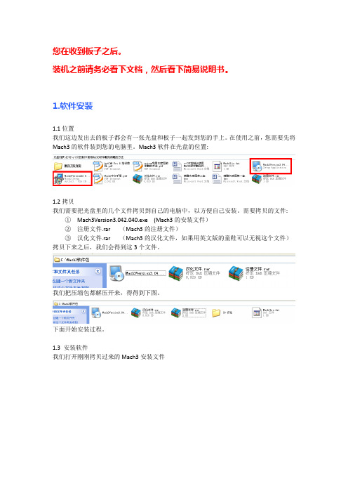
我们的控制板分为2个版本。一个为24V版本,一个为5V版本。
如果您购买的是5V版本的,那么您在接16个输入口的时候,请一边接在5V端,另外一端接在输入端。
如果您购买的是24V版本的,那么您在接16个输入口的时候,请一边接在V+端,另外一端接在输入端。
请注意,不要同时在V+和5V上都接开关。
我们打开刚刚拷贝过来的Mach3安装文件
打开.
点Next
勾选同意,然后继续点Next进入下一步.
我们缺省安装在C盘,或者自己在红圈内选择安装位置。(建议默认安装在C盘)继续点Next
下面是驱动,以及一些软件。红色框勾选的Parallel Port Driver为并口驱动,如果是用笔记本的童鞋千万记得要勾掉,要不然会直接电脑死机,完成后,点Next
根据自己是3轴还是4轴来勾选上。
另外就是Dir LowActive(方向)Step Low Active(低电平有效)可以根据自己的驱动器来勾选.
点击应用,保存
3.5急停,限位设置
上面这排意思:
1)X++ X轴正限位
2)X- - X轴负限位
3)X Home X原点
后面Y,Z,A同上。作用分别是X轴的正限位,X轴负限位.X轴回原点
点Next进入下一步
继续Next
安装过程
这个界面是因为我安装了并口驱动所以有的,如果没有安装并口驱动的童鞋会直接跳到这个界面
点Finish完成Mach3的安装。
在桌面就会出现这几个图标:
其中Mach3 Mill是我们经常会直接用到的
1.4 LazyCam的安装
LazyCam是Mach3自带的一个软件。也可以用ArtCam来替代,ArtCam可能会更方便。这里仅仅介绍下他的安装方法:
埃克森EXXT调试说明
0.80
F2-05 切换频率 2
5.0O
5.00
5.00
F2-06 电流环比例增益
150
60
60
F2-07 电流环积分增益
10
30
30
3
电气安装调试说明
EXXT 系列 M3000N A3.1
F2-10 电梯运行方向
F3-00 F3-01 F3-02 F3-03 F3-04 F3-05 F3-06 F3-07 F3-11 F3-18 F3-19 F3-20 F4-00 F4-03 F5-01 F5-02 F5-03 F5-04 F5-05 F5-06 F5-07 F5-08 F5-09 F5-10 F5-11 F5-12 F5-13 F5-14 F5-15 F5-16 F5-17 F5-18 F5-19 F5-20 F5-21 F5-22 F5-23 F5-24 F5-25
详见主机铭牌
详见主机铭牌
50
F1-05 额定转速
详见主机铭牌
详见主机铭牌
1460
F1-06 同步机初始角度
根据主机
0
F1-08 同步机接线方式
0或8
0
0:无操作 1:电机带 0:无操作 1:电机带
F1-11 自学习选择
负载调谐 2:电机无负 负载调谐 2:电机无负
0
载调谐 3:井道自学习 载调谐 3:井道自学习
按实际设定 1:方 按实际设定 1:方
向脉冲取反 2:仅脉冲 向脉冲取反 2:仅脉冲
0
取反 3:仅方向取反 取反 3:仅方向取反
0
0
0
0
0
0
0.6
0.6
0.6
2.5
2.5
西电油机操作说明书
Réf. constructeur : Ed. 03/2004 Réf. GPAO : 33502016501SDMO Kerys使用说明书1. MICS Kerys 介绍 (2)1.1. 目标和结构................................................................................................................................... (2)2. 界面使用 (2)2.1.键盘介绍..................................................................................................................... ... ... ... ... (2)2.1.1 显示器 (3)2.1.2 数字键........................................................................................................................................... (3)2.1.3 发电机操作键............................................................................................................... ......... ... (3)2.1.4 导航键 (3)2.1.5 信号控制键 (3)2.1.6 LED 指示灯 (4)2.2. 界面环境............................................................................................................................ .. (4)2.2.1 屏幕描述 (5)2.2.2 初始屏幕 (5)2.2.3 导航屏幕..................................................................................................................................... (6)2.2.4 操作和设置屏幕..................................................................................................... ... ... ... ... ... (6)2.2.4.1.上边指示器............................................................................................................... ... ......... ... (7)2.2.5保存修改....................................................................................................................... ......... . (7)3. 使用主菜单 (8)3.1.主菜单布局图 (8)3.1.1发电机运行模式 (8)3.1.2根据操作模式的菜单布局 (13)3.2. 操作菜单................................................................................................................................ (14)3.2.1 运行 (15)3.2.2功能键 (15)3.2.3 同步专栏 (16)3.2.4 主要的测量概要.......................................................................................................... ... (17)3.2.5 测量 (18)3.2.5.1. 发电机组电气测量.................................................................................. ... ... ... ... ... (18)3.2.5.2. 汇流母线/ 电网电气测量............................................................................. (19)3.2.5.3. 机械测量...................................................................................................... ......... ... ... ......... (20)3.2.5.4. 发电机组谐波测量................................................................................. ... ... ... ... (21)3.2.5.5. 汇流母线/ 电网谐波测量............................................................................ ... ... ... ... (21)3.2.5.6. 旋转磁场测量..................................................................................................... ............ (22)3.2.6 告警和故障 (23)3.2.7 用户设置 (23)3.2.7.1. 设置要点 (24)3.2.7.2. 功率极限.................................................................................................................... (25)3.2.7.3. Wattmetric control / 常规参量 (25)3.2.7.4. Wattmetric control / 极限............................................................................................. ... (27)3.2.7.5.发电机组优先权......................................................................................................... ... (27)3.2.7.6. 用户参数 (28)3.3. 地域性参数 (29)4. 解释 (30)4.1. 术语表 (30)1. MICS Kerys 介绍1.1. 目标和结构MICS KERYS 系统设计包括一些为测试、控制和设置用的电子模块,及保护油机按照自己的状态或部分按工厂的设置运行。
CK SWITCHES KT Series 螺纹螺帽锐化按键开关说明书
Dimensions are shown: mmSpecifications and dimensions subject to changeT a c t i l e S w i t c h esOrientation and Mounting Style SM Top Gullwing JM Top J Bend ****SAM Right angleSA1M Right angle with front solder padSA2M Right angle with front solder pad and pick & place tab SA3MRight angle with pick & place tabActuatorB0* Soft, flush B1* Soft, 0,64 mm B2* Soft, 2,24 mm P2** Hard, 2,36 mm P3** Hard, 1,12 mm P4** Hard, 3,96 mmS1*** ø0,1” for Press Fit Caps S2*** ø0,14” for Snap Fit Caps (with anti-rotation)3Features/Benefits• Full SMT side-actuated tact switch• SMT top-actuated tact switch with G or J terminations • High shear force with extended bracket • Easy to pick & place with top plate tab • Rubber or hard plastic actuator • Press fit or snap fit caps• RoHS compliant and compatibleTypical Applications • Telecommunications • Computer products • Instrumentation • Power supplySpecificationCONTACT ARRANGEMENT: SPST, N.O.TERMINALS: SMT terminationElectricalCONTACT RATING: 1.0 VA max. @ 32 V AC or DC max.ELECTRICAL & MECHANICAL LIFE: 100,000 make-and-break cycles at full load.DIELECTRIC STRENGTH: 250 Vrms min. @ sea level.CONTACT RESISTANCE: Below 50 mΩ typ. initial @ 2-4 V DC, 100 mA.INSULATION RESISTANCE: 109 Ω min.EnvironmentalOPERATING TEMPERATURES: A g version: -40˚C to 90˚CA u version: -40˚C to 125˚C ProcessSOLDERABILITY: Per MIL-STD-202F method 208D, or E IA RS-186E method 9 (1 hour steam aging).DEGREE OF PROTECTION: IP57; protection against harmful dust deposits, full-scale voltage protection.PackagingSwitches supplied in anti-static tape and reels per EIA 481-2. Tape and cover strip are conductive for use near statically sensitive components.NOTE : Specifications listed above are for switches with standard options.For information on specific and custom switches, consult Customer Service Center.BUTTONTo order buttons in bulk* B0, B1 & B2 available with A, A1 & A3 mounting bracket only.** P2, P3, P4 actuators suitable with A1 & A2 mounting bracket only.*** S1 & S2 available with A1 & A2 mounting bracket only.**** JM available with BO, B1, B2, P2, P3, P4 without mounting bracket.Button Color 90 Black80 Ivory (natural)40 RedSpecifications and dimensions subject to change3,18. * B0, B1 & B2 available with A, A1 & A3 mounting bracket only.** P2, P3, P4 actuators suitable with A1 & A2 mounting bracket only.*** S1 & S2 available with A1 & A2 mounting bracket only.**** JM available with BO, B1, B2, P2, P3, P4 without mounting bracket.Specifications and dimensions subject to changeT a c t i l e S w i t c h e sSpecifications and dimensions subject to changeTactile SwitchesSA3M RIGHT ANGLE WITH PICK & PLACE TAB(.125)3,18(.067)1,71(.114)2,904,61PAD LAYOUTSAM & SA3M MOUNTING BRACKETPAD LAYOUTSA1M & SA2M MOUNTING BRACKET24SCHEMATICDimensions are shown: mmSpecifications and dimensions subject to changeT a c t i l e S w i t c h esBUTTONTo order buttons in bulkMaterials: Nylon Finish: Gloss。
Exheat 工业 FXE 型号防爆封闭式加热器与 FXT 型号温控器安装操作和维护说明书
INSTALLATION OPERATION ANDMAINTENANCE INSTRUCTIONS FOREXHEAT INDUSTRIAL FXE TYPE FLAMEPROOF ENCLOSURE HEATERS&FXTTYPE THERMOSTATSPlease read these instructions thoroughly before installation and ensure they are passed on tothe end-user.1.0GENERAL1.1All work should be carried out by suitable qualified personnel.1.2Carefully remove all protective packaging and visually inspect unit for any transit damage.1.3FXE/FXT’S must be handled with care and stored in dry conditions.1.4CAUTION–These units are designed for industrial use only and additional personnelprotection against contact with hot surfaces may be required in some installations.1.5Before connection ensure that the supply corresponds with that specified on the rating label.1.6Each unit must be protected by a suitably rated over current device.1.7All prevailing rules,regulations and bylaws in force at the time and place of installationmust be observed.1.8The units should be securely fixed in position and all‘end user’made connections checkedfor tightness before energising.1.9Any modification not carried out by Exheat Industrial Ltd or its approved agent willinvalidate certification and warranty.1.10Reference must be made to IEC/EN60079-14&IEC/EN60079-17.1.11All electrical testing must be carried out in a non-hazardous area.2.0INSTALLATION2.1The installer or end user shall ensure that the unit has free and unrestricted airflow.2.2The FXE must only be orientated vertically.2.3The FXT/FXT-I can be orientated vertically or horizontally.2.4The appliances must be securely fitted to an enclosure wall or din rail using the mountingbracket provided.2.5The cable glands and bungs must not be removed under any circumstances.3.0ELECTRICAL SUPPLY CONNECTION3.1The flying lead provided must be terminated using suitable terminals in a certified enclosurein accordance with IEC/EN60079-14(see fig.1).4.0EARTH CONNECTION4.1WARNING–the FX Range MUST BE EARTHED.4.2The external earth connection is located on the bracket and is supplied with an M5fixingnut and bolt.4.3The internal earth connection is within the cable provided and should be terminated in asuitable terminal in accordance with IEC/EN60079-14.5.0OPERATION5.1WARNING–The FX range enclosure heater and thermostat must at no time be coveredduring operation,as this could lead to dangerous overheating.5.2Once energized the enclosure heater will continue to operate until de-energised by anexternal control device(such as the FXT range).5.3The permitted ambient temperature range for operation of the standard FX Range is as fig.2.The end user must ensure that no excursions outside these ambient temperature limits areallowed to occur at any time.6.0MAINTENANCE6.1All prevailing site safety regulations shall be adhered to at all times.6.2Before and whilst any maintenance activity is carried out,it must be ensured that there areno hazardous gases present.6.3Equipment is to be fully isolated from the electrical supply before and whilst any work isbeing carried out.6.4Any damage or faults should be notified to Exheat Industrial Ltd immediately.6.5Any replacement parts required must be obtained directly from Exheat Industrial Ltd.Theuse of any other parts will void any certification and warranty.6.6Reference must be made to IEC/EN60079-17(especially table1)in addition to thefollowing recommendations:6.6.13Monthlya.Generally inspect the equipment for external damage.b.Ensure that the spaces between the element fins remain clear and that the airflowremains unrestricted.7.0Marking and certification reference FX Enclosure Heaters.7.1II2G D(ATEX certified units only)Ex d IIC(Gas)T3or T4GbEx t IIIC(Dust)T200°C or T135°C DbIP6X-50°C<T amb<+80°CDo not open while energisedDo not open in presence of explosive atmosphereLCIE12ATEX3040X(ATEX certified units)IECEx LCI120008X(IECEx certified units)7.2Marking and certification reference FXT Enclosure Thermostats.II2G D(ATEX certified units only)Ex d IIC(Gas)T6GbEx tb IIIC(Dust)T85°C DbIP6X-60°C<T amb<+78°CDo not open while energisedDo not open in presence of explosive atmosphereLCIE12ATEX3086X(ATEX certified units)IECEx LCI120030X(IECEx certified units)Fig.1.Model LIVE NEUTRAL EARTHFXE HEATERS RED/BROWN BLACK/BLUE GREEN AND YELLOWSUPPLY LIVE SWITCHED LIVE NEUTRALS EARTHFXT THERMOSTAT RED/BROWNBLACK/BLUE(SLEEVED TO SUITLIVE)NO NEUTRAL ISREQUIREDGREEN ANDYELLOWFXT–ITHERMOSTAT IN LINE WITH FXE RED/BROWN N/A BLACK/BLUEGREEN ANDYELLOWFig.2.Model Voltage Output Mounting T-Class AmbientFXE30110-120V220-254VAC30W Wall/RailT3T480°C40°CFXE50110-120V220-254VAC50W Wall/RailT3T480°C40°CFXE75110-120V220-254VAC75W Wall/Rail T360°CFXE100110-120V220-254VAC100W Wall/Rail T360°CFXT110-120V220-250VAC1.3A MAXALLOWEDWall/Rail T678°CFXT-I110-120V220-250VAC1.3A MAXALLOWEDWall/Rail T678°CThis Page Intentionally Left BlankThis Page Intentionally Left Blank。
ктек 专业电池管理器说明书
E NGENERATE EXPLOSIVE GASES DURING NORMAL BATTERY OPERATION. FOR THIS REASON, IT IS OF UTMOST IMPORTANCE THAT, YOU FOLLOW THE INSTRUCTIONS EACH TIME YOU INSTALL THE CHARGER.b) To reduce risk of battery explosion, follow these instruc-tions and those published by the battery manufacturerand the manufacturer of any equipment you intend to use in vicinity of battery. Review cautionary marking on these products and on engine.c) Disconnect battery poles before installationd) D250S DUAL is not reverse polarity protected.11. PERSONAL PRECAUTIONSa) Consider having someone close enough by to come toyour aid when you work near a lead-acid battery.b) Have plenty of fresh water and soap nearby in case bat-tery acid contacts skin, clothing or eyes.c) Wear complete eye protection and clothing protection.Avoid touching eyes while working near battery.d) If battery acid contacts skin or clothing, wash immediatelywith soap and water. If acid enters eye, immediately flood eye with running cold water for at least 10 minutes andget medical attention immediately.e) NEVER smoke or allow a spark or flame in vicinity of bat-tery or engine.f) Be extra cautious to reduce risk of dropping a metal toolonto battery. It might spark or short-circuit battery or other electrical part that may cause explosion.g) Remove personal metal items such as rings, bracelets,necklaces, and watches when working with lead-acidbattery. A lead-acid battery can produce a short-circuitcurrent high enough to weld a ring or the like to metal,causing a severe burn.h) Use charger for charging a LEAD-ACID battery only. Donot use battery charger for charging dry-cell batteries that are commonly used with home appliances. These batter-ies may burst and cause injury to persons and damage to property.i) Never charge a frozen battery.12. PREPARING TO CHARGEa) If necessary to remove battery from vehicle to charge,always remove grounded terminal from battery first. Make sure all accessories in the vehicle are off, so as not tocause an arc.b) Be sure area around battery is well ventilated while bat-tery is being charged.c) Clean battery terminals. Be careful to keep corrosion fromcoming in contact with eyes.d) Add distilled water in each cell until battery acid reacheslevel specified by battery manufacturer. Do not overfill.For a battery without removable cell caps, such as valveregulated lead acid batteries, carefully follow manufac-turer’s recharging instruction.e) Study all battery manufacturer’s specific precautions whilecharging and recommended rates of charge.f) Determine voltage of battery by referring to vehiclesmanual.13. CHARGER LOCATIONa) Never place charger directly above battery beingcharged; gases from battery will corrode and damagecharger.b) Never allow battery acid to drip on charger when read-ing electrolyte specific gravity or filling battery.c) Do not set a battery on top of charger.14. FOLLOW THESE STEPS WHEN BATTERY IS INSTALLED IN VEHICLE. A SPARK NEARBATTERY MAY CAUSE BATTERY EXPLOSION. TO REDUCE RISK OF A SPARK NEAR BATTERY:a) Position cords to reduce risk of damage by hood, door ormoving engine part.b) Stay clear of fan blades, belts, pulleys, and other partsthat can cause injury to persons.c) Check polarity of battery posts. POSITIVE (POS, P, +)battery post usually has larger diameter than NEGATIVE (NEG, N, -) post.d) Determine which post of battery is grounded (connected)to the chassis. If negative post is grounded to the chassis (as in most vehicles) see (e). The battery charger can not be used with positive-grounded batteries.e) For Negative-grounded vehicle, connect POSITIVE con-nector from battery charger to POSITIVE (POS, P, +)ungrounded post of battery. Connect NEGATIVE connec-tor from battery charger to vehicle chassis or engine block away from battery. Do not connect to carburetor, fuellines, or sheet-metal body parts. Connect to a heavy gage metal part of the frame or engine block.f) When disconnecting charger, always do so in reversesequence of connecting procedure and break first connec-tion while as far away from battery as practical.15. FOLLOW THESE STEPS WHEN BATTERY IS OUTSIDE VEHICLE.A SPARK NEAR BATTERY MAY CAUSE BATTERY EXPLOSION. TO REDUCE RISK OFA SPARK NEAR BATTERY:a) Check polarity of battery terminals. POSITIVE (POS,P, +) battery post usually has a larger diameter thanNEGATIVE (NEG, N, -) post.b) Attach at least a 24-inch-long 6-gauge (AWG) insulatedbattery cable to NEGATIVE (NEG, N, —) battery post. c) Connect POSITIVE charger connector to POSITIVE (POS,P, +) post of battery.d) Position yourself and free end of cable as far away frombattery as possible – then connect NEGATIVE chargerconnector to NEGATIVE (NEG, N, -) post of battery.e) Do not face battery when making the final connection.f) When disconnecting charger, always do so in reversesequence of connecting procedure and break first connec-tion while as far away from battery as practical.SAFETY• D250S Dual and SMARTPASS is designed for 12V lead-acid batteries. Do not use the unit for any other batteries.• Disconnect battery poles before installation• D250S Dual is not sprak proof.• The installation must include a fuse according to recommen-dations in table “CABLE DIMENSIONS”.All installations on boats must follow ISO 10133. Please note!1. Connections from the battery must be fused close to the battery.2. Batteries must be permanently mounted in ventilated areas.3. Cables must be placed in tubes, separated from cables for 110/230 V (shore power), or be attach to the surface every 300 mm.4. Cables in the engine room must be rated to withstand 70°C/158°F5. For a permanently connencet battery charger: GROUNDING INSTRUCTIONS— This battery charger should be connected to a grounded, metal, permanentE Nwiring system; or an equipment-grounded conductor should be run with circuit conductors and connected to equipment-grounded terminal or lead on battery charger. Connections to battery charger should comply with all local codes and ordinances.D250S DUALThe D250S Dual has 2 inputs. The Service battery will be charged from the alternator, solar panel, or both in combina-tion. The solar panel adjusts itself to the Starter battery voltage. The Starter battery will be charged and maintained directly by the solar panel if the Service battery is fully charged.D250S DUALFEATURES:• Multi-step 20 A temperature compensated battery charging and battery maintenance.• Battery separation of Starter and Service batteries.• Maximum power point tracking for solar panels charging the Service battery.• Two power source inputs (alternator, solar, wind, Supply battery and other).• Coordination of the two inputs, allowing parallel operation. • The solar input will also maintain the Alternator battery.• Built in battery guard for the Alternator battery.battery +battery +Vehicle ground/E NSMARTPASSSMARTPASS can operate as a stand-alone unit, but works best in combination with D250S Dual. The SMARTPASS createsa priority path for charging the Service battery to rechargeit more quickly and efficiently. Attached energy sources like solar, wind or shore power will charge both the Service and the Starter batteries through the SMARTPASS. Service batteries that are overheated due to age, high ambient temperature or other battery problems will be protected from high alternator current.SMARTPASSFEATURES:The CTEK SMARTPASS adds additional functionality for higher output alternators, larger battery banks and/or high parallel loads.• Separation of consumers and Service batteries during charging, which improves the charging capacity signifi-cantly, and lowers the consumer voltage, which increases expected service life of lights and other electronics.• Service battery watch, which avoids harmful deep dis-charges that otherwise would shorten battery life. The bat-tery watch also protects navigation, radio and emergency light from being out of electricity.• Over-temperature protection of Service battery. High bat-tery temperature could significantly reduce battery life.• Maintenance charge of Starter battery, which simplifies installation with fewer components.• Simplified installation of AC/DC chargers (shore power). Only one output from the AC/DC charger needed.The CTEK SMARTPASS is designed to work together with 1-2 CTEK D250S DUAL, but can also be used alone.Negative cable Alternator ServiceE NINSTALLATION OF UNIT1. Attach the temperature sensor holder on a flat surface onone Service battery. Position it as close as possible to apositive post.2. Use the included drill template. Wiring is simplified if theunits are installed according to the drill template, but other setups are possible.3. Install the unit(s) on a surface where it can be properlyfixed and where the unit is not exposed to fuels, oils orsplashes of dirt.4. Mount the unit with screws intended for the surface andattach it with one screw in each of the four holes in thecorners of the unit. See picture 1. Mount the unit with M4 or ST4.2 screws. The required torque depends on the sur-face for mounting. Fig. 1 shows a CTEK D250S. The same procedure is used for all devices.5. Attach the cables and mount the cable screws with atorque of 7 Nm/62 Lb-In. Use tool – hand power without tools is not enough.6. The ground cable of the SMARTPASS should be connect-ed to the ground screw of the DUAL or to any convinientground connection point.INSTALLATION OF CABLESFigure 1Figure 22Nm/18 Lb-In7Nm/62 Lb-InAllen keyWARNING!D250S DUAL andSMARTPASS is not reversepolarity protected.Disconnect battery polesbefore installation.WARNING!D250S DUAL is not sparkproof. Provide for goodventilation.E NE NE NE NNE EN • 23E N26 • EN2012–05–3020020400ATEMPERATURE PROTECTION SMARTPASS has a temperature sensor cable. The units willautomatically protect the service battery if the temperatureand charging voltage together are too high. Charging will thenonly be performed by the D250S battery charger. The temper-ature should be measured close to the battery, therefore attach the sensor to the battery.LIMITED wARRANTYCTEK SWEDEN AB, issues this limited warranty to the original purchaser of this product. This limited warranty is not trans-ferable. The warranty applies to manufacturing faults and material defects for 2 years from the date of purchase. The customer must return the product together with the purchase receipt. This warranty is void if the battery charger has been opened, handled carelessly or repaired by anyone other than CTEK SWEDEN AB or its authorised representatives. One of the screw holes in the bottom of the charger is sealed. Removing or damaging the seal will void the warranty.CTEK SWEDEN AB makes no warranty other than this limited warranty and is not liable for any costs other than those men-tioned above. For example, consequential damages are not covered. Moreover, CTEK SWEDEN AB is not obligated to any other warranty other than this warranty.CTEK PRODUCTS AREFor latest revised user manual and CTEKs professional customer support: (EU), (US).Bye-mail:************(EU),***********************(US).By telephone: +46(0) 225 351 80 (EU), (330) 963-0981 (US).。
- 1、下载文档前请自行甄别文档内容的完整性,平台不提供额外的编辑、内容补充、找答案等附加服务。
- 2、"仅部分预览"的文档,不可在线预览部分如存在完整性等问题,可反馈申请退款(可完整预览的文档不适用该条件!)。
- 3、如文档侵犯您的权益,请联系客服反馈,我们会尽快为您处理(人工客服工作时间:9:00-18:30)。
一、E XAKT的介绍EXAKT是一款在存活分析和可靠性的区域,特别是在基于状态维修的(Conditon-based Maintenance,CBM)区域进行数据分析和决策制定。
CBM指一起使用和状态相关的项目的寿命、诊断数据来制定替换决策的一个维修程序。
EXAKT向项目提供一个关于替换或者大修的计划,它使在每个单元时间内平均维修费用最小,就意义而言它是最优的。
而这个计划正是基于CBM模型的,它的参数来自项目的历史(寿命和诊断数据)。
1.EXAKT的结构包括两个模块:EXAKT建模模块(EXAKTm)和EXAKT决策模块(EXAKTd)。
图1。
图1 EXAKT的两个软件模块EXAKT的主要功能:●数据的转换以及预处理(EXAKTm)。
●建模(EXAKTm)。
建立CBM模型●制定决策(不仅有EXAKTd,还有EXAKTm参与)。
2.EXAKT的作用●预测系统/设备失效;●估计系统/设备剩余寿命;●定义预防性更换周期,降低装备寿命周期费用,提高装备可靠性;●实现装备费用、可靠性、故障风险的平衡。
3.EXAKT收益●提高使用可靠性:在故障发生之前,对故障进行预测,提高可靠性,降低使用费用;●“O”设备停机时间:以高置信度水平,在装备处置退役之前,保证系统正常运行;●精确制定维护计划:精确预测系统/零件剩余寿命;●减少对“无影响数据”分析;●降低维护费用:通过优化预防性更换的频率,来降低维护费用;●高效的设备/零件更换计划:通过精确的预测设备/零件的寿命;●精确的失效预测:通过预测单元级水平,对复杂设备进行预测;●精确的预测模型:适用于零部件/系统;二、EXAKT的使用1.EXAKTm的使用1.EXAKTm主窗口如图2。
图2 EXAKTm主窗口2.File,New,新建一个空WMOD数据库(命名强烈建议采用_WMOD为结尾)与放置MES数据库文件在同一地方,不然后边不可导入外部数据库。
Creat。
Modeling(在菜单条上),Data Setup,进入一个脚本编辑器界面,输入与外部的MES 数据库连接的语句,如图3中,Execute,Save。
MES数据库表格也会显示在左图3边的窗口,成为激活状态,可以通过双击打开每个表格检查,熟悉它们。
或者可以File,Open打开一个已经存在的WMOD数据库。
3.Data Preparation,Enter General Data,出现图4界面,对其输入,例如,图5。
图4图5*注:当每次输入数据确定后,后面的图标依然是灰色的,并不能马上变成亮的,图标需要一定的时间来等待先于它之前的所有数据都已经配置好。
4.With Covariates(Complete),(我们等待了不到一分钟的时间With Covariates (Complete)以及后面的图标才成亮的,被激活)。
当数据只包含了失效的和挂起的信息,没有检查的信息,可使用Without Covariates这个选项,这将指导形成一个简单的Weibull 分析,并且计算最优的寿命和替换决策。
而当数据包含检查记录的时候,就要使用With C-Ovariates(Complete)、With Covariates(Iterpolated)、With Covariates(Incomplete)、Marginal Analysis、或者Combined Analysis选项。
在这里以With Covariates(Complete)为例说明。
图6。
图6进行上个步骤之后,Events和Inspections表格合并成一个表格C_Inspections,仍保留原来两个表格。
后边的计算将使用该表格进行计算。
5.Modeling,Weibull PHM,Select Covariates,出现Model Variables界面,对其进行输入,如图7。
点击ok以后,会生成对该模型的报告。
如图8。
“Summary of Events and Censored Values”显示了被分析的数据的总体上总结。
“Sample Size”是13表示有13个历史。
其中6个以失效而结束,3个(Censored(Def))在失效之前就结束,4个(Censored (Temp))在当前建立模型的时候还在运行中。
“Summary of Estimated Parameters”提供了建立的子模型的结果。
“Sign”的值表示该参数是否重要的,也就是是否它和失效有关联。
在图8中,Shape、Iron和Lead是重要参数,而Calcium和Magnesium是不重要的。
“P-value”的值越高,它和失效的风险的关系就越小。
图7图86. Select Covariates,重新选择协变量(covariates),只保留和失效的风险有关系的协变量,建立新的子模型,生成报告,如图9。
图97.Modeling(在菜单条上),Select Current Model,出现了图10,对其进行选择,则选择了刚才建立的子模型为激活状态。
图108.Modeling(在右边的Procedures窗口中的),Weibull PHM,Summary Report,之后生成图11的报告。
图11“PHM Fits Data”是Not rejected(*)表示该子模型可被接受的置信水平是95%,到此我们已经成功地创建了一个比例风险模型(Proportional Hazards Model,PHM)。
9.Transition Probability Model,Covariates Bands,对“Covariates”选择不同图12变量会在“Interval Start Points”下面生成不同的状态的分割区间。
软件用它们来构建转换可能性模型。
这个模型会计算在接下来的检查时间的一个间隔里从一个状态跳转入另一个状态的可能性。
图12选择Iron,点击确定。
10.Transition Rates,Display Survival,出现Display Survival Probabilities界面,Working Age:8000,Observation Interval:200Hrs,图13。
点击Report按钮,生成如图14报告。
左边的被分割的状态区间表示Iron在工作寿命是8000小时时的,上面那一行则表示Iron的工作寿命是8200小时时的状态区间,200就是一个检查时间的间隔,前面对其进行了设置。
例如“0-4.004”和“4.004-9.009”的值是0.301615,表示了Iron 在8000小时时状态“0-4.004”在8200小时时跳转为“4.004-9.009”的可能性为30.1615%。
图13图1411.Decision Model,Decision Model Parameters,出现Decision Model Parameters 界面,使Replacement(C):1200,Failure(C+K):6000,Cost Unit:$,Inspection Interval:250,图15点击OK之后,在工具条中点击出现图16报告。
该报告中,显示出了最优的策略在花费上比只在失效时替换的策略每工作一小时节省1.14383,只在失效时替换的策略,设备从开始到结束工作了3941.95h,所以平均每小时的花费是6000/3941.95=1.5220而最优策略的两次替换之间的时间是3326.4h,所以平均每小时的花费是(1200*94.2%+6000*5.8%)/3326.4=0.378258。
图15图1612.Decisions,出现Last Histories界面,对出现在Select Ident下面的进行选择,图17,点击Report,则可以生成最近的历史的其他单元的决策报告,再点击,使用Page Down可以查看不同单元的决策报告图18。
图17图1813.ModelDbase,Connect to DatabaseScript,点击左边的窗体,不然Connect to DatabaseScript不能被激活。
对其进行脚本编写,从而将所建立的最优化的决策模型输出到维修系统中。
图19。
这时左边的窗体上添加了几个新表格链接,点击其中Decisions表格查看,图20。
图19图2014.ModelDbase,Store the Decision model,至此将所建立的决策模型输出到了DMDR 数据库中,图20。
可以关闭EXAKTm模块。
图202.EXAKTd的使用1.File,New,新建一个空的WDEC决策数据库(强烈建议命名以_WDEC结尾),进入图21界面。
图212.Setup,Connect to model database script,进入脚本编写器,进行编写脚本,使与外在的注入了在EXAKTm模块建立的模型的MDMR数据库链接,如图22。
点击Save后,图22出现图23所示。
这时,对于每个单元,如图17-67单元,在右边已经生成了它的最优策略。
图233.点击上图中的Trans Oid Anal,Reports,Creat Reports,在生成的对话框中全部选择,图24,则会生成全部的决策报告。
点击,就能全屏显示,按Page Down可以查看各个报告。
图25。
图24也可以只点击一个单元如17-66,在随后的对话框中进行选择想要生成的决策报告,和上个步骤是一样的。
图25 到这,EXAKTd模块的基本使用也讲完。