ASME标准-管道
美标与国标管道壁厚对照表
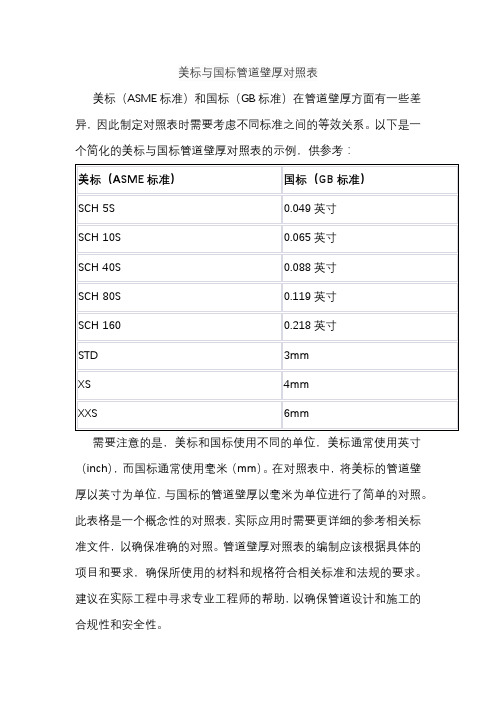
美标与国标管道壁厚对照表
美标(ASME标准)和国标(GB标准)在管道壁厚方面有一些差异,因此制定对照表时需要考虑不同标准之间的等效关系。
以下是一个简化的美标与国标管道壁厚对照表的示例,供参考:
需要注意的是,美标和国标使用不同的单位,美标通常使用英寸(inch),而国标通常使用毫米(mm)。
在对照表中,将美标的管道壁厚以英寸为单位,与国标的管道壁厚以毫米为单位进行了简单的对照。
此表格是一个概念性的对照表,实际应用时需要更详细的参考相关标准文件,以确保准确的对照。
管道壁厚对照表的编制应该根据具体的项目和要求,确保所使用的材料和规格符合相关标准和法规的要求。
建议在实际工程中寻求专业工程师的帮助,以确保管道设计和施工的合规性和安全性。
ASME标准-管道

ASME标准-管道压力管道设计常用ASME标准,其中包括组件尺寸型式标准和材料标准。
组件型式标准规定了组件的型式、系列、尺寸、公差、试验要求,以及该组件可采用的材料标准等。
材料标准规定了适用的对象、原材料品种、化学成分、机械性能、制造工艺、热处理、无损检查、取样和性能检验、质量证书、标志等。
常用的组件型式标准包括钢管、管件、阀门、法兰、垫片和紧固件。
例如,钢管常用的标准有ANSI/ASMEB36.10M和ANSI/ASMEB36.19M;管件常用的标准有ANSI/ASMEB16.9、ANSI/ASMEB16.1和ANSI/ASMEB16.28;阀门常用的标准有ANSI/ASMEB16.34、API599、API600、API602和API609;法兰常用的标准有ANSI/ASMEB16.5、ANSI/ASMEB16.36、ANSI/ASMEB16.42和ANSI/ASMEB16.47;垫片常用的标准有ANSI/ASMEB16.20和ANSI/ASMEB16.21;紧固件常用的标准有ANSI/ASMEB18.2.1和ANSI/ASMEB18.2.2等。
材料标准主要集中收录在ASMEIIA篇铁基材料,B篇非铁基材料,C篇焊条、焊丝填充金属,D篇性能,以及一些增补内容。
与压力管道设计相关的典型的为A篇、D篇等。
A篇的主要分类有:钢板、薄板和钢带,公称管(Pipe),管子(Tube),钢法兰、配件、阀门及零件,压力用钢板、薄板和钢带,结构钢,钢棒材,钢螺栓材料,钢坯和锻件,钢铸件,耐腐蚀钢和耐热钢,锻轧铁、铸铁和可锻铸铁,以及方法标准等。
这些材料标准规定了原材料品种、化学成分、机械性能、制造工艺、热处理、无损检查、取样和性能检验、质量证书、标志等。
材料的表示方法通常使用“标准号-级别”及UNS编号。
例如,304是一种级别,而TP316中的TP表示管材,代表英文单词TUBE&PIPE的首字母。
F316中的F表示锻件,是FORGING的缩写。
管道施工规范(ASMI)

管道施⼯规范(ASMI)C O N T E N T SPA GE1. GEN ERAL1.1 Scope 31.2 Specific Job Requirements 31.3 Codes and Standards 31.4 Related Engineering Specifications 31.5 Units 32. GEN ERAL REQUIR EMENT2.1 Qualification 42.2 Material 43. FABRICATION3.1 General 53.2 Cutting 53.3 End Preparation 63.4 Alignment and Trimming73.5 General Requirement for Welding113.6 Welding Rods 113.7 Welding 123.8 Marking 203.9 Storing 204. ASSEMBLING AND ERECTION4.1 General 214.2 Flanged Joint 224.3 Threaded Joint 224.4 Mechanical Joint 226.INSPECTION, EXAMINATION AND TES TINGExtent of Inspection, Examination and Testing6.2 Non-Destructive Examination 287.PRESS URE TES TING-PROCESS8. COATONG AND WRAPPING OF PIPING9. CLEANING AFTER PIPING ASS EMBLING AND ERECTION 31 1. GENERAL1.1 ScopeThis procedure covers the general requirements for the piping construction work, including test andinspection of plant to be carried out by China National Chemical Engineer NO.7 Construction Company Ltd (hereinafter referred to as CC-7).1.2 Specific Job RequirementsSpecific job requirements which are attached to this procedure cover modifications to this specification, Customer’s special or local requirements as well as specific job data pertinent to t his specification. Where Specific Job Requirements are in contradiction to this specification, Specific Job Requirements shallgovern.1.3 Codes and StandardsInternational codes and standards supplementary in related to this specification shall be as follows:(1) ASME B31.3 Process Piping(2) ANSI/ASME B1.20.1 Pipe Threads, General Purpose (Inch)(3) ASME/ANSI B16.5 Pipe Flanges and Flanged Fittings(4)ASME Boiler and Pressure Vessel Code, Section V(5)Section II part C Material Specifications-Welding Rods, Electrodes and Filler Metals(6)Section IX Qualification Standard for Welding and Brazing Procedures,Welders, Brazers, and Welding and Brazing operators1.4 Related Engineering S pecificationsThe related BASF-YPC Company Ltd. Specification to supplement this specification are as follows:(1) RPI 94/1 General Requirements for BASF Technology Projects(2) 40-010-00-0-0-00-003 Positive Material Identification(3) 50-010-00-0-0-00-003 Piping Material Specification(4) 50-010-00-0-0-00-004 Steam Tracing & Winterization(5) 50-010-00-0-0-00-006 Piping Identification System(6) 50-010-00-0-0-00-009 Pressure Testing-Process & Utility Piping(7) 50-010-00-0-0-00-024 Welding and Non-Destructive Examinations of Piping Systems(8) 50-010-00-0-0-00-025 Shop and Field Fabrication ,Installation and Handling-Processand utility Piping(9) 50-010-00-0-0-00-034 Pipe Support1.5 UnitsThe AA/AE Unit shall be applied as the measurement system for documents and drawings. Nominal size of piping components shall be measured in Inches, for which the abbreviation is NPS. Nominal flangerating shall be as per the applied codes and standards.2. GEN ERAL REQUIR EMENT2.1 Qualification(1) Persons who are engaged for welding including tack welding and support welding work shall havepassed the welding performance qualification test before commencement of welding works and shallbe performed in accordance with ASMEB31.3para.328.(2) Welding Procedure Specification and the Procedure Qualification Record shall be approved by TECand owner before commencement of welding work. Production welding shall not commence beforereceipt of written approval and authorization to start welding.(3) Persons who are engaged for pipe-fitting, assembling, erection work, shall be fully trained and shallhave the qualification of Employer.License, certificate, pass or qualification issued from Authorities,if available, shall be effective.(4) The inspector nominated for the job must be a specialist or an expert in respective examinations and licensed or qualified by an internationally recognized Association and/or by any statutory requirement applicable.2.2 Material2.2.1Piping Materials shall be in accordance with DOC.No.50.010.AA.0.0.00.5012.2.2It is applicable to use other alternate materials which shall be approved by TEC and owner.2.2.3Selection of welding rod shall be in accordance with Welding Procedure Qualification testRecord (PQR) unless otherwise approved by TEC and owner.2.2.4Quality certificate of technical gas to be used for the work such as argon gas, propane gas, etc. shall be provided with approval of TEC before work starts.3. FABRICATION3.1 General3.1.1Fabrication requirement shall be in accordance with ASME B31.3 unless otherwise specified.3.1.2Fabrication shall be executed in accordance with the related Engineering Specification and the drawings, document stated in Par. 1.4 and 2.3 of this specification.3.1.3The bolt holes of flanges shall be located symmetrically from a vertical center line in a horizontal pipe line, and from plant north in a vertical pipe line unless otherwise indicated in the drawing.3.1.4Marking of piping materials shall be in accordance with Para.10,0 in Doc.No.50.010.00.0.0.00.0253.2 Cutting3.2.1Cutting line shall be marked on pipe. Where the material marking will become invisible after cutting, additional material marking shall be provided.3.2.2In the case of gas cutting, cutting surface shall be ground off to remove any edge and roughness and be made flush and smooth so as not to harm welding quality.3.2.3In the case of gas cutting, cutting slug sticked inside pipe shall be completely removed, especially for boring of pipe for weld branch.3.3 End Preparation3.3.1End preparation for butt weld shall be in accordance with Table 3.3.1, or any other which meets the WPS.(1) Welding Bevels for Butt WeldsTable 3.3.1Unit: mm(2)Shape of beveling other than mentioned in Table 3.3.1 shall be in accordance with the WPS approved by TEC and owner..3.4 Alignment and Trimming3.4.1Root gap for butt-weld shall be in accordance with the WPS.3.4.2In the case of butt welding pipe and/or fitting having unequal wall thickness, of which the difference is more than 3 mm in outer surface and/or 1.5 mm in inner surface, the end of the thicker pipe shall be trimmed by grinding as per the Fig. 3.4.2 (a), (b) and (c) shown below. The gradient of this trimmingshall be less than 30 between worked and unworked parts shown as below.Unit: mmOver 2 or 0.5 x tm(a) Whichever is less30?(c)t m : required minimum wallthickness of pipe.Fig. 3.4.2Note:In the case that “Special End Detail” is specified in the Specification H -103 for the pipe and/or fitting of which the nominal wall thickness is 30 mm and over, the end preparation shall be in accordance with such provision.3.4.3 Branch connections which abut the outside surface of the run pipe shall be contoured for groove welds which meet the WPS requirements [see Fig. 3.4.3 (a) and (b)].Branch connection which are inserted through a run opening shall be inserted at least as far as the inside surface of the run pipe at all points [see Fig. 3.4.3 (c)].g = Root gap per WPS ? m = The lesser of 3.2 mm or 0.5 TbFig. 3.4.33.4.4 When a pipe having a longitudinal weld seam is used in a horizontal line, the pipe shall be laid so that thelongitudinal weld seam is not on bottom or top of the pipe. (These should be located at least 45o from the bottoms of the pipe).A llocation and relation among circumferential, longitudinal and other (branch, support, etc.) welds are shown in the Fig. 3.4.4 (a), (b) or (c).(1) Circumferential jointIn case ?g mmgg0 mm - 3 mm(a)(b)(c)T b T b T bNote : L1≥100mmL2≥50mm or 6 x Tw which is greater Tw: Pipe Wall thicknessFig. 3.4.4 (a)(2) Branch pipe and weld line on run pipeFig. 3.4.4 (b)Notes: 1. L and L1 show the distance between both toes of the bead.2. L shall be three times the pipe thickness or over.3. L1 shall be more than 100mm.(3) Support/Shoe and weld seam of main pipeDetail “A”3.6 General Requirement for Welding3.6.1Requirement and criteria for welding shall be as follows, unless otherwise specified in the drawings:(1) Welding shall be performed in accordance with WPS.(2) Welding shall not be carried out in adverse weather conditions where there is impingement of rain,snow, sleet storm or excessive wind at the working area, unless appropriate and adequate protection is provided.(3) The level shall be fully cleaned so that there is no rust, oil, paint, sand, moisture, etc. remaining.Where a bevel is not to be welded immediately it shall be protected to prevent contamination.(4) All slag, weld spatter and flux remaining on any bead of welding shall be removed before the nextbead is deposited.(5) Spatter, slag, etc. on the weld or in the heat affected zone, shall be thoroughly removed to the metal surface.(6) Arc strikes on base metal shall be avoided at all times. Arc strike shall be ground flush and liquid penetrant tested. Any defect shall be ground out and weld repaired.(7) Material of wire brush shall be properly selected for working carbon steel respectively. They shallalways be kept separate and never used on anything other than the designation.(8) Welding for a welded joint valve shall be carried out with the valve opened.(9) Weld internal protrusion at the weld neck joint of an orifice flange, shall be removed flu sh andsmooth with a grinder. Any concavity in the root, shall be weld repaired and ground flush and smooth.Fig. 3.4.4 (c)“A”(10) All welds including socket welding shall be performed at least 2 layers weld and end point of weldat each layer shall be changed (stagger).(11) Welding of dissimilar metals shall be carried out at fabrication shop if possible.3.7 Welding Rods3.7.1Brand name of welding rod to be used at shop and site shall be approved by TEC and owner before workstarts and that shall be used only.3.7.2 Each welder shall be immedatory provided with a portable dryer to shop/Field work after withdrowelectrode from main oven container.3.7.3 Baking and Holding temperature of electrode shall be performed with manufacture’s recommendation. 3.8 Welding 3.8.1Tack welding shall be carried out as follows:(1) Both root and bridge tack welding method may be applied.(2) Avoid wrong fit-up which would cause residual stress.(3) Keep the correct root gap by using spacers according to WPS.(4) Welding condition of tack welding shall be in accordance with WPS.(5) Provide sufficient external pipe clamps or internal spiders for setting up.(6) Ensure the contact surface of the clamps or spiders are made of the same base metal, or an inertcompound.(7) Bridge tack shall never be hammered off. Bridge tacks shall be removed by grinding or gas cutting.Gas cutting shall only be performed at the upper part of the weld toe and flush surface of base metalby grinding, and then a liquid penetrant examination shall be carried out. Any defect shall beground out and weld repaired.3.8.2Butt joint welding of pipes shall be performed as follows:(1) Welding shall be performed in accordance with WPS.(2) Circumferential butt welding shall be performed without the use of a backing ring unless specified inWPS.(3) Before welding of the root, both ends of the root tack weld bead shall be prepared with a grinder asshown in the following illustration in order to make complete fusion.L1: Max 15mm for NPS 24”Max 40mm for NPS>24”Fig. 3.8.23.8.3Branch connections shall be made by using the fittings as specified in the Doc.No.50.010.AA.0.0.00.501. However, where the branch is to be welded directly to the main run in accordance with Doc.No.50.010.AA.0.0.00.501.or Piping Arrangement Drawing, welding shall be performed, unlessotherwise specified, shown in following Fig. 3.8.3:Fig. 3.8.3Notes: 1. Throat thickness “tc” shall be of 0.7Tb (minimum 6.4 mm).2. The symbols used in these figures are as follows:Th: nominal thickness of run pipeTb: nominal thickness of branch pipeTr: nominal thickness of reinforcement pad3. At first, weld part ① and prepare the weld surface with a grinder, then weld the part ②.4.Where reinforcement is necessary, it is indicated in the Piping Arrangement Drawing andNotes for Piping Drawings.3.8.4Fillet welding of pipe to slip-on and socket weld flanges shall be performed as shown in following Fig.Fig. 3.8.4Notes: 1. T: thickness of pipet : thickness of flange hub2. If 1.4 T is larger than t, t shall be taken.3.8.5Socket welding of pipe components other than flanges shall be performed as shown in following Fig.3.8.5:3.11 Marking3.11.1 All piping components for which welding has been completed shall bear the painted marking with the identification symbol of the welder as confirmation.3.11.2 Spool piece No. shall be clearly marked on fabricated components.3.12 Storing Inside of fabricated components shall be cleaned by air blowing, then openings of fabricated components shall be covered with suitable materials so as not to enter the foreign matters such as sand, mad, etc. into piping components. Gasket surface of flange, thread, welding bevel shall be protected from any damage due to cleaning work and handling of storing.4. ASSEMBLING AND ERECTION4.1 General4.1.1 Before assembling of piping, actual tolerance causing from foundation, steel structure, equipmentinstallation work shall be considered for the piping assembling work.4.1.2 Excessive stress shall not be allowed to the nozzles of rotating machine when the flange of fabricated component is connected, such work shall be carried out in the presence of person in charge of themechanical work. And openings such as flanged joints of a pump, compressor, etc. shall be kept covered with thin metal plate or other solid blinds with a handle to prevent dust and/or foreign material from entering into the machine.4.1.3 If hot work to be performed in the vicinity of instrument control or power cable duct, an adequateprotective cover shall be provided in advance so as not to damage the cables.4.1.4 When work is carried out in the vicinity of piping made of, or lined with special materials such asplastics, rubber, glass, etc., care shall be taken so as not to damage them.4.1.5 Valves shall be assembled in clean condition, they shall not be opened during piping erection except that welding and heat treatment of a welded valve joint shall be carried out with valve opened.4.1.6 If cutting, making of holes to the assembled piping and such kind of work is carried out at assembledplace due to the reason of modification, improvement, etc., cut piece and foreign materials shall be removed from inside of piping and it shall be confirmed that the inside of piping is cleaned.T = nominal wall thicknessc xT4.1.7Valves having flow direction shall be installed to conform the flow direction in accordance with pipingdrawings. Care shall be taken to the valves in case valve flow direction is reversed against the flowdirection of pipe line.4.1.8It is prohibited to use small size piping, pumps, instrument etc. as scaffolding or working stage.4.1.9The following requirement shall be observed for piping support.(1) Pipe supports shall be fabricated and installed in accordance with Pipe Hanging Details.(2) As a rule the location of pipe-supports shall be in accordance with the Piping Arrangement Drawingand Hook-up Drawing.(3) The pre-setting pieces of the pipe hanger shall be removed after completion of leak test of the pipeline. However, pipe lines which will be insulated, it shall be removed after completion of theinsulation work.(4) A shoe support shall be attached to the pipe in accordance with the drawings. It is not permitted totack-weld a shoe support to the pipe rack, where the shoe support is not to be permanently fixed tothe pipe rack.(5) When supports are installed on building or such kind of structure, permis sion of installation shall begiven by TEC before installation.4.2 Flanged Joint4.2.1Any damage to the gasket seating surface which would prevent gasket seating shall be repaired, or theflange shall be replaced.4.2.2Flanged joints shall be bolted up, after checking the alignment of the flange centers and the parallelness of flange faces, to ensure that the contact faces bear uniformally on the gasket. Bolting-up shall ensure that bolt tension is spread uniformly around the flange.4.2.3Particular care shall be exercised to ensure that all bolt, nut and gasket are correctly installed inaccordance with the requirements of DOC.No.50.010.A.A.0.0.00.501.4.2.4When assembling flange connections, paste shall be applied to the gasket and bolts. Thes e preventseizure of nuts and adherence of gaskets. Reference of pastes and their applications shall be in SpecificJob Requirement.4.3 Threaded Joint4.3.1The standard to be applied to all threads shall be ANSI/ASME B1.20.1 Pipe Threads (NPT).4.3.2Lubricant shall be removed completely from the thread and inside of pipe after threading.4.3.3In a threaded joint between pipe and flange, the length of thread on the pipe shall be such that the end ofthe pipe is short of the gasket surface on the flange by 1.5 to 3.0 mm when screwed-in.4.3.4Thread shall be jointed with full coupling between straight pipes, and piping shall have union joints in consideration with repairing at leak test.4.3.5Threaded joints shall be sealed with tape or threading compound, unless there is restriction from process requirement.4.3.6Seal welding of threaded parts, if specified, shall be performed after the part is screwed-in completelywithout using paste or oil and fully cleaned, decreased and dried out. Reinforce ment of the seal weldbead shall cover completely the remaining thread and must be at least 2-layers weld using a suitable size of electrode.4.4 Mechanical Joint4.4.1Mechanical Joint other than flanged joint and threaded joint shall be in accordance w ith manufacturer’s instruction or drawing.4.4.2Care shall be taken to avoid distorting the sheet when incorporating such joint into piping assemblies by welding.6. INSPECTION, EXAMINATION AND TES TING6.1 Extent of Ins pection, Examination and TestingPrior, during and after completion of the works, the following examination and tests shall be performed: 6.1.1In-Process Inspection(1) Prior to Commencement of Work(2) Prior to Welding(3) After Welding(4) After Complet ion of Work6.1.2 REPAIR WELDING(1) No repairs by welding from the outside are allowed for the following conditions:excessive penetrationexcessive burn-through(2) Root defects on inaccessible joints shall be cut-out and rewelded, unless otherwise agreed uponwith Welding Engineering.(3) Prior to repair, cause of the weld defect should be established. All cracks, non-fusion, lack of penetration, excessive slag or porosity, beyond the requirements, shall be removed by gougingand/or grinding. Complete removal of a defect shall be verified by magnetic particle or liquidpenetrant examination. Re-welding shall be done per applicable approved repair welding procedure.The number of repairs at the same location on a specific weld shall be limited to two times.(4) A ll repairs shall comply with code requirements and shall be re-examined in accordance with the requirements of this specification when completed.(5) Repair welding of base metal defects is not allowed prior to approval of the procedure for this typeof repairs and the extent of NDE after repair.6.2 Non-Destructive Examination6.2.1The weld joints of piping shall be examined to the extent specified in NDE index with the following random examination procedure:(1) The examination made at random shall consist of examining not less than one production weld joint selected from each production weld joint lot made by the same welder or welding operator definedas follows.The above each production weld joint lot means;each 20 production weld joints or less for 5 % random examination.(2) The examination shall be applied to the entire length of weld of the selected joint.(3) The weld joints between dissimilar materials shall be examined by the method used for the material requiring the more stringent examination.6.2.2 When a random or spot examination of weld joints reveals a defect, the progressive examination for the same lot defined in Par. 6.2.1 shall be carried out as per the following procedure.(1) Two additional weld joints of the same lot, by the same welder shall be given the same type of examination; and(2) If the weld joints examined as required by (1) above are acceptable, all items represented by thi s additional examination shall be accepted; but(3) If any of the items examined as required by (1) above reveals a defect, two further weld joints of the same lot by the same welder shall be examined for each defective item found by that examinatio n;and(4) If all the items examined as required by (3) above are acceptable, all items represented by thisadditional examination shall be accepted; but(5) If any of the items examined as required by (3) above reveals a defect, all items represented by the random examinations shall be fully examined and repaired or replaced as necessary to meet the requirement of this specification.(6) The defective item(s) revealed during progressive examination, shall be repaired or replaced and reexamined at above each step as specified in Par. 6.1.2.6.2.3 The requirement for radiographic examination shall as follows:(1)Radiographic examination of butt welds shall be in accordance with ASME B31.3 para.344.5.(2)All butt welds between existing lines and new tie-in lines shall be 100% radiographed.(3)At least the specified percentage of the number of welds made by each welder shall be radiographed around their total circumference. If a welder makes less than 10 welds, two of these shall b e fully radiographed.(4)The first three welds of each welder shall have 100% radiography regardless of pipe diameter andwallthickness. This evaluation shall be made on a common size if possible and shall be performed asquickly as possible upon completion of the weld.(5)Acceptance of weld defects for both random (limited) and 100% radiography shall be in accordancewith ASME B31.3 para.341.3.2. However, incomplete root penetrations are not allowed.(6)Use Image Quality Indicators (IQI) shall be of the wire type in accordance with IIW/IIS 62-60, orunless otherwise approved by TEC and Owner.(7)Only lead screens may be used.(8)The gamma-ray technique may be used when prior agreed upon in writing with the Authorized Inspector. When the gamma-ray technique is agreed upon only very fine grain films equal toASTM-E94, type 1 (such as AGFA-D4) shall be used. The application of Co-60 source shall beavoided.(9)Where necessary to achieve the required minimum film sensitivity (image quality),the radiationsourceshall be placed inside the pipe (single wall technique).(10)In radiographing a continuous length of weld, the separate radiographs shall overlap sufficiently (minimum 10mm).(11)A record shall be kept of the quality and extent of each wlder’s work. Examination results of 100% radiographed Pipe classes and of limited/random radiographed Pipe classes shall be recorded separately.Results of 100% radiography are not valid for the minimum extent of limited examination per welder.(12)The NDE Contractor is fully responsible to meet the local requirements for radioactive, radiationsafety.(13)Films of repair welds will get the same film number as the original films with the addition of suffix Z for the first repair; Y for the second repair. For field welding film number suffixes R1 and R2 shallbeused.(16) Prior to issue to the authorized Inspector, all radiographs must have been reviewed (and results of review recorded) by the Contractor’s qualified inspector.(17)All original radiographes, including those of repaired welds, shall be presented to the authorized Inspector for Examination, together with complete filled out exposure reports.(18)All defects repaired by welding (other than non-pressure attachments) which are previously radiographed, shall be re-radiographed after repair in accordance with this specification.(19)The following detail of radiographic examination shall be specified by NDE contractor and shall be approved by TEC and owner.a.Film type and size for each pipe size and thickness.b.Exposure technique for each pipe size and thickness.c.Nos of Film for each pipe size and thickness.d.Type and material of the penetrometer for each material, pipe size and thickness.e.Type of source for each pipe size and thickness.6.2.4Requirement for liquid penetrant and magnetic examination particle examination shall be as follows: (1)Liquid penetrant examination and Magnetic Particle examination shall be in accordance with ASMEB31.3 para.344.3.(2) Procedure for random examination shall be in accordance with NDE Index.(3) Only the Yoke Technique with wet particle of magnetic particle e xamination shall be performed.7.PRE SS URE TE S TING-PROCE SS8. COATONG AND WRAPPING OF PIPING9. CLEANING AFTER PIPING ASS EMBLING AND ERECTIONCleaning work after piping assembling and erection shall be performed as required by TEC.。
ASME标准中文版
ASME标准中文版ASME标准中文版ASME B16.20-1993管法兰使用环连接式、螺旋缠绕式和夹套式金属垫片。
这些垫片广泛用于管道系统中,以确保管道的完整性和安全性。
ASME B16.21-1992管法兰使用非金属平垫片。
这些垫片通常由柔软的材料制成,如橡胶、聚四氟乙烯或纤维素。
它们的优点在于可以适应不同的管道尺寸和形状,并且具有很好的密封性能。
这些标准的主要目的是确保管道系统的安全和可靠性。
它们规定了垫片的尺寸、形状、材料和安装要求,以确保它们能够有效地防止泄漏和其他问题。
在使用这些垫片时,必须遵循严格的安装和维护程序。
这包括正确的选择和安装垫片,以及定期检查和更换垫片以确保其完好无损。
总之,ASME B16.20-1993和ASME B16.21-1992标准是管道系统中必不可少的组成部分。
它们确保了管道的安全和可靠性,并为管道系统的设计和维护提供了重要的指导。
XXX Code is a set of XXX and pressure vessels。
The Code is divided into several ns。
each of which XXX.n I of the XXX。
n。
n。
and testing of power boilers。
XXX materials。
welding。
and safety.n II of the XXX divided into several parts。
each of which covers a specific type of material used in the XXX ferrous materials。
while Part B covers non-XXX C covers welding rods。
wires。
and filler materials。
and Part D XXX.n III of the XXX of nuclear power plant components。
solidworks管道ASME介绍及规格对应表

NPS--- Nominal Pipe Size 代表公称直径DN
Inch---英寸
ASME---美国机械工程师学会(American Society of Mechanical Engineers)
ASNI---美国国家标准学会(American National Standards Institute)
RTee---三通管道,Inch4×4×1.5的意思是三通接口端中与原管道连接的端口的工程直径是4英寸,另一个旁路接口端的公称直径是1.5英寸。
ANSI与GB压力等级对照表
管道公称直径一览表(美国ASME标准)
管道公称直径一览表(美国ASME标准)
注:STD 指标准壁厚管XS 加厚壁厚管XXS 特别加厚壁厚管
S指不锈钢系列,不带S指其他钢种焊接和无缝钢管壁厚系列数据中系列加上Sch与没有Sch的意义相同如Sch5S与5S意义相同,Sch30与30意义相同。
美标管道标准

美标管道标准美国标准协会(ANSI)制定了一系列的管道标准,这些标准涵盖了管道材料、设计、制造和安装等方面,对于保障管道工程的安全和可靠性起着重要的作用。
本文将对美标管道标准进行介绍和解析,希望能够为相关领域的专业人士提供一些参考和帮助。
首先,我们来谈谈美标管道材料的标准。
在美国,管道材料的标准由ASTM(美国材料与试验协会)制定。
ASTM针对不同材料,制定了一系列的标准规范,包括钢管、塑料管、铸铁管等。
这些标准规范涵盖了材料的化学成分、力学性能、尺寸偏差、表面质量等方面的要求,确保了管道材料的质量和可靠性。
其次,美标管道设计的标准也是非常重要的。
在管道工程设计中,需要考虑到管道的承压能力、温度变化、介质流动等因素,以确保管道在使用过程中不会发生泄漏、断裂等安全事故。
ASME(美国机械工程师协会)制定了一系列的管道设计标准,包括ASME B31.1(电站管道系统)、ASME B31.3(化工厂管道系统)等。
这些标准规定了管道的设计原则、计算方法、材料选用、焊接要求等内容,为管道设计提供了重要的依据。
除此之外,美标管道制造和安装的标准也是不可忽视的。
在管道制造过程中,需要严格按照相关标准进行生产,确保管道的质量和性能符合要求。
而在管道安装过程中,需要考虑到管道的支吊架、焊接工艺、防腐蚀措施等方面,以确保管道安装的质量和可靠性。
ASME B31.4(液体输送管道系统)和ASME B31.8(天然气输送管道系统)等标准规定了管道制造和安装的要求,为相关工作提供了指导和依据。
综上所述,美标管道标准涵盖了管道材料、设计、制造和安装等方面,对于管道工程的安全和可靠性起着重要的作用。
相关领域的专业人士应当熟悉这些标准,并在工程实践中严格遵守,以确保管道工程的质量和安全。
希望本文能够为大家对美标管道标准有所了解,并在实际工作中加以应用和推广。
管道材料等级制定与ASME标准

管道材料等级制定与ASME标准一、压力管道设计常用ASME标准这里有两个标准,一个是组件尺寸型式标准(我国也有相应组件形式标准),另一个是材料标准(我国没有对材料形成专门的标准化)。
型式标准规定了组件的型式、系列、尺寸、公差、试验要求,以及该组件可采用的材料标准等。
材料标准规定了适用的对象、原材料(坯料)品种(采用锻轧Wrought或锻件Forged)、化学成分、机械性能、制造工艺(包括焊接)、热处理、无损检查、取样和性能检验、质量证书、标志等。
1. 典型的组件型式标准1)钢管ANSI/ASME B36.10M 无缝及焊接钢管ANSI/ASME B36.19M 不锈钢无缝及焊接钢管2)管件ANSI/ASME B16.9 工厂制造的钢对焊管件ANSI/ASME B16.1 承插焊和螺纹锻造管件ANSI/ASME B16.28 钢制对焊小半径弯头和回弯头3)阀门ANSI/ASME B16.34 法兰连接、螺纹连接和焊接连接的阀门API 599 法兰或对焊连接的钢制旋塞阀API 600 法兰或对焊连接的钢制闸阀API 602 紧凑型碳钢闸阀API 609 凸耳型对夹蝶阀4)法兰ANSI/ASME B16.5 管法兰和法兰管件ANSI/ASME B16.36 孔板法兰ANSI/ASME B16.42 球墨铸铁法兰和法兰管件ANSI/ASME B16.47 大直径钢法兰API 601 突面管法兰和法兰连接用金属垫片5)垫片ANSI/ASME B16.20 管法兰用缠绕式、包覆式垫片和环槽式用金属垫片ANSI/ASME B16.21 管法兰用非金属平垫片6)紧固件ANSI/ASME B18.2.1 方头和六角头螺栓和螺纹ANSI/ASME B18.2.2 方头和六角头螺母7)管件ASMEI B16.9 工厂制造的锻钢对焊管件ASME B16.11 承插焊和螺纹锻钢管件MSS-SP-43 锻制不锈钢对焊管件2. 材料标准ASTM/ASME材料标准主要集中收录在ASME II A篇铁基材料,B篇非铁基材料,C篇焊条、焊丝填充金属,D篇性能,以及一些增补内容。
压力管道设计常用ASME标准

一、压力管道设计常用ASME标准这里有两个标准,一个是组件尺寸型式标准(我国也有相应组件形式标准),另一个是材料标准(我国没有对材料形成专门的标准化)。
型式标准规定了组件的型式、系列、尺寸、公差、试验要求,以及该组件可采用的材料标准等。
材料标准规定了适用的对象、原材料(坯料)品种(采用锻轧Wrought或锻件Forged)、化学成分、机械性能、制造工艺(包括焊接)、热处理、无损检查、取样和性能检验、质量证书、标志等。
1. 典型的组件型式标准1)钢管ANSI/ASME B36.10M 无缝及焊接钢管ANSI/ASME B36.19M 不锈钢无缝及焊接钢管2)管件ANSI/ASME B16.9 工厂制造的钢对焊管件ANSI/ASME B16.1 承插焊和螺纹锻造管件ANSI/ASME B16.28 钢制对焊小半径弯头和回弯头3)阀门ANSI/ASME B16.34 法兰连接、螺纹连接和焊接连接的阀门API 599 法兰或对焊连接的钢制旋塞阀API 600 法兰或对焊连接的钢制闸阀API 602 紧凑型碳钢闸阀API 609 凸耳型对夹蝶阀4)法兰ANSI/ASME B16.5 管法兰和法兰管件ANSI/ASME B16.36 孔板法兰ANSI/ASME B16.42 球墨铸铁法兰和法兰管件ANSI/ASME B16.47 大直径钢法兰API 601 突面管法兰和法兰连接用金属垫片5)垫片ANSI/ASME B16.20 管法兰用缠绕式、包覆式垫片和环槽式用金属垫片ANSI/ASME B16.21 管法兰用非金属平垫片6)紧固件ANSI/ASME B18.2.1 方头和六角头螺栓和螺纹ANSI/ASME B18.2.2 方头和六角头螺母7)管件ASMEI B16.9 工厂制造的锻钢对焊管件ASME B16.11 承插焊和螺纹锻钢管件MSS-SP-43 锻制不锈钢对焊管件2. 材料标准ASTM/ASME材料标准主要集中收录在ASME II A篇铁基材料,B篇非铁基材料,C篇焊条、焊丝填充金属,D篇性能,以及一些增补内容。
- 1、下载文档前请自行甄别文档内容的完整性,平台不提供额外的编辑、内容补充、找答案等附加服务。
- 2、"仅部分预览"的文档,不可在线预览部分如存在完整性等问题,可反馈申请退款(可完整预览的文档不适用该条件!)。
- 3、如文档侵犯您的权益,请联系客服反馈,我们会尽快为您处理(人工客服工作时间:9:00-18:30)。
一、压力管道设计常用ASME标准这里有两个标准,一个是组件尺寸型式标准(我国也有相应组件形式标准),另一个是材料标准(我国没有对材料形成专门的标准化)。
型式标准规定了组件的型式、系列、尺寸、公差、试验要求,以及该组件可采用的材料标准等。
材料标准规定了适用的对象、原材料(坯料)品种(采用锻轧Wrought 或锻件Forged)、化学成分、机械性能、制造工艺(包括焊接)、热处理、无损检查、取样和性能检验、质量证书、标志等。
1. 典型的组件型式标准1)钢管ANSI/ASME B36.10M 无缝及焊接钢管ANSI/ASME B36.19M 不锈钢无缝及焊接钢管2)管件ANSI/ASME B16.9 工厂制造的钢对焊管件ANSI/ASME B16.1 承插焊和螺纹锻造管件ANSI/ASME B16.28 钢制对焊小半径弯头和回弯头3)阀门ANSI/ASME B16.34 法兰连接、螺纹连接和焊接连接的阀门API 599 法兰或对焊连接的钢制旋塞阀API 600 法兰或对焊连接的钢制闸阀API 602 紧凑型碳钢闸阀API 609 凸耳型对夹蝶阀4)法兰ANSI/ASME B16.5 管法兰和法兰管件ANSI/ASME B16.36 孔板法兰ANSI/ASME B16.42 球墨铸铁法兰和法兰管件ANSI/ASME B16.47 大直径钢法兰API 601 突面管法兰和法兰连接用金属垫片5)垫片ANSI/ASME B16.20 管法兰用缠绕式、包覆式垫片和环槽式用金属垫片ANSI/ASME B16.21 管法兰用非金属平垫片6)紧固件ANSI/ASME B18.2.1 方头和六角头螺栓和螺纹ANSI/ASME B18.2.2 方头和六角头螺母7)管件ASMEI B16.9 工厂制造的锻钢对焊管件ASME B16.11 承插焊和螺纹锻钢管件MSS-SP-43 锻制不锈钢对焊管件2. 材料标准ASTM/ASME材料标准主要集中收录在ASME II A篇铁基材料,B篇非铁基材料,C篇焊条、焊丝填充金属,D篇性能,以及一些增补内容。
与压力管道设计相关的典型的为A篇、D篇等。
A篇的主要分类有:钢板、薄板和钢带,公称管(Pipe),管子(Tube),钢法兰、配件、阀门及零件,压力容器用钢板、薄板和钢带,结构钢,钢棒材,钢螺栓材料,钢坯和锻件,钢铸件,耐腐蚀钢和耐热钢,锻轧铁、铸铁和可锻铸铁,以及方法标准等。
材料表示方法用"标准号-级别"及UNS。
如304是级别。
TP316前面的TP表示管材,英文单词TUBE & PIPE的首个字母。
F316前面的F表示锻件,是FORGING的缩写。
一般在ASME里,很多都是引用A STM标准,并在前面加个S,如A312被ASME纳入后为SA312。
在ASTM标准中,A表示为A系列材料,当然还有B、C等。
美国高合金钢用UNS牌号表示,它是按美国钢铁协会AISI的编号表示方法转过来的,比如,AISI把18-8不锈钢记为UNS No S 30400(3代表镍铬钢),ASTM引用过来叫它为304型,于是各国也跟着这么叫,成为普遍的表示法。
还比如316、31 6L、321、347、320、904等。
ASME(或ASTM)对公称成分相同(UNS No 号相同)的不同钢材产品,还用不同的标准区分。
比如板材SA-240(牌号304),管材有213、249、312、376、430(牌号都是TP304)等,而锻件A-182,牌号F304。
ASTM的记法,如A-516,A代表钢铁金属,516只是个序号,后面跟着年号。
ASME等同采用ASTM的记法后在最前面加S。
再有,B-表示非铁基金属,如S B-409。
下面列举一些典型的ASME管道材料:1.公称管1)SA-106 高温用无缝碳钢公称管中、低碳钢,其等级分A、B、C三级。
C%≤0.25%~0.35%;合金总量<0.2%。
2)SA-312/SA-312M 无缝和焊接奥氏体不锈钢公称管适用于高温及一般腐蚀用。
级别有TP304H、TH316H、TP321H等9种。
3)SA-333/SA-333M 低温用无缝和焊接公称管适用于低温公称壁厚的无缝以及焊接的碳钢、合金钢公称管。
其级别有1、3、4、6、7、8、9、10、11共9种。
4)SA-335/SA-335M 高温用无缝铁素体合金钢公称管级别有P1、P2、P5、P5c、P9、P11、P12、P15、P21、P22。
5)SA-709/709M 无缝及焊接的铁素体、奥氏体不锈钢公称管2.钢法兰、配件、阀门及零件1)SA-105/SA-105M 管道元件用碳钢锻件适用于室温和高温下工作的压力系统中锻制碳素钢管道构件。
2)SA-182/SA-182M 高温用锻制或轧制合金钢公称管道法兰、锻制管配件、阀门和零件级别较多,如F1、F2、F5、F12-1、F12-2、F304H、F316LH等。
3)SA-234/SA-234M 中、高温用锻制碳钢和合金钢管道配件适用于最新版的ANSI B16.9、ANSI B16.11、ANSI B16.28及MSS SP-79和MSS SP-95所包括的无缝的及焊接结构的锻制碳钢和合金钢管配件;这些管配件采用中温及高温的压力管道和压力容器制造。
级别有WPB、WPC、WP-1、WP-2、WPR等多种。
4)SA-403/SA-403M 锻轧奥氏体不锈钢管配件包括了若干级别的奥氏体不锈钢合金,并分别依据所适用的ANSI或MSS尺寸及额定压力标准,使用WP或CR前缀来标志钢的级别。
5)SA-420/SA-420M 低温用锻造碳钢和合金钢管配件适用于ANSI B16.9、ANSI、B16.11 、ANSI B16.28及MSS SP-79和MSS SP-95最新版标准的锻制碳钢和合金钢无缝焊接结构管配件。
等级有WPL3、WPL 6、WPL8、WPL9。
6)SA-815/SA-815M 塑性加工成形铁素体、奥氏体及马氏体不锈钢配件。
3.钢螺栓材料1)SA-193/SA-193M 高温用合金钢和不锈钢材料适用于高温压力容器、阀门、法兰及管配件用合金钢和不锈钢螺栓材料。
材料类别包括铁素体钢和奥氏体钢,其级别如B5、B8等多种。
2)SA-194/SA-194M 高温高压螺栓用碳钢和合金钢螺母包括从M6到M100的各种碳钢、合金钢、马氏体不锈钢、奥氏体不锈钢螺母。
奥氏体级别,加前缀8和9;铁素体级别有1,2,2H,2HM,3,4,6,6F,7,7M,16。
二、压力管道材料等级表内容简述管道材料等级中包含了材料规定,是针对一系列介质条件而编制的管道器材应用明细表。
它是根据管道系统中的温度和压力及腐蚀性来分类的。
通过情况下,材料等级表的内容有:1)等级名称(或等级号)、设计条件(设计压力、设计温度和介质)、法兰公称压力等级、材料腐蚀余量等。
2)钢管外径尺寸系列信息及壁厚钢管外径尺寸系列有大小外径之分,ASME标准采用大外径。
外径尺寸定位后,意味着与其相关的钢管、管件、阀门、法兰、垫片、紧固件、附件等都要与之匹配。
就法兰系列而言,一类是以200℃作为计算基准温度的"欧式法兰",一类是以大约430℃(对150LB级则是300℃)作为基准温度的"美式法兰"。
ASME标准的钢管外径尺寸系列标准为ANSI B36.10、ANSI B36.19,其公称直径范围为DN6~DN2000 mm。
钢管壁厚的表示方法有三种,如管表号(SCH)、壁厚(mm)、重量(STD、XS、X XS)。
3)钢管、管件(弯头、三通、异径管、支管接头等)、阀门、法兰、垫片、紧固件等全面一些,在标识时除了提供钢管、管件等的材料(标准)、连接形式(对焊、承插焊、螺纹连接)、表面状态(无缝、有缝)等内容外,还应提供组件型式标准。
4)管道分支信息即管道分支表,提供主管与支管连接应匹配的规定。
通常情况下,应优先选用标准管件,如三通/四通(等径、异径)、支管接头等。
若出现主、支管相差太大无法选择时,才使用非标接头形式,并需要计算是否需要进行补强等加强措施。
三、ASME B31.3钢管壁厚计算制定材料等级表需要计算的内容有两种情形,其一是前面提到的开孔补强计算,其二是这里提及的钢管(含弯头等)的强度计算。
ASME B31系列钢管壁厚计算的公式有多种,对于石化项目必须按B31.3管道规范中的方法进行强度计算。
强度计算需要的条件为设计条件(温度、压力)、材料许用应力、钢管外径(或内径)、质量系数(也称焊接接头系数)、温度影响系数,此外还要考虑材料腐蚀余量、加工裕量等。
壁厚计算的结果是进行钢管(及弯件)壁厚选用标准尺寸的依据。
这种方法与容器壁厚选用的方法基本一致。
弯头等管件的壁厚也有计算方法,但是在通常情况下,是以直管的计算为依据选用标准厚度即可。
而开孔补强计算方法就与容器的完全一致了。
四、选材与腐蚀进行材料等级表制定需要考虑的事项有多种,除了前面提及材料满足强度要求只是其中之一,还要考虑操作介质的性质、操作工况等引起材料的各种腐蚀。
就腐蚀形式而言,根据腐蚀发生的机理可划分为化学腐蚀、电化学腐蚀和物理腐蚀三类。
根据腐蚀形态可划分为均匀腐蚀、局部腐蚀和应力腐蚀三类。
其中局部腐蚀又可分为电偶腐蚀(如碳钢与不锈钢接触并处于电解质环境中)、点蚀(如对奥氏体不锈钢材料的应用要注意氯离子的含量)、缝隙腐蚀、晶间腐蚀(如高温时奥氏体不锈钢产生的晶界贫铬)。
因此就需要了解材料的耐腐蚀性能,并查询金属腐蚀相关手册等资料。
五、铁碳合金相图管道材料等级表的技术主要在对材料性能的掌握上,因此各设计院通常是由机械专业的人来进行此方面的工作。
而材料的关键技术又与了解其本质-铁碳合金相图是密切相关的。
铁碳合金相图是以温度为纵坐标,碳含量(组元)为横坐标。
表示在接近平衡条件(铁-石墨)和亚稳条件(铁-碳化铁)下(或极缓慢的冷却条件下)以铁、碳为组元的二元合金在不同温度下所呈现的相和这些相之间的平衡关系。
相图在金属加工和工程应用中是一个很重要的工具,从相图中可以查到合金的溶点和凝固点,根据相图可以确定合金热加工时的加热温度和热处理温度,由此可以预测合金的性能。
该相图中有两个组元,即Fe和Fe3C。
其中,Fe的性能表现为强度和硬度较低,塑性和韧性较好;Fe3C为具有复杂晶格结构的间隙化合物,其性能表现为硬而脆。
四个基本相,即液相(L )、铁素体(α)、奥氏体(γ)和渗碳体(Fe3C);此外还有一个次生相珠光体(P)。
其中,铁素体为碳在α-Fe中的间隙固溶体,具有体心立方晶格,溶碳量较少,室温溶碳量为0.008%,属常温组织;奥氏体为碳在γ-Fe中的间隙固溶体,具有面心立方晶格结构,溶碳量较大,属高温组织,奥氏体具有良好的塑性,故金属热变形加工多是在这种相状态下进行的;渗碳体为金属键及化学键的结合物,属于常温组织;珠光体为铁素体和渗碳体的混合物,既具有很好的强度和硬度,又具有良好的塑性和韧性,属常温组织。