
清末民初老照片
1916年5月 27日照
1917年孙中山 与宋庆龄照于大 元帅府
宋庆龄为 孙中山守灵
1925年孙中山 丧礼完后宋庆龄 于4月11日返回 上海。
1927年,宋庆 龄摄于武汉
1931年的宋庆 龄
1981年5月8日, 宋庆龄在人民大 会堂接受加拿大 温哥华维多利亚 大学授予她的荣 誉法学博士 学 位。之后1981 年5月29日,宋 庆龄病逝。
珍妃——光绪的 可意人儿 光绪身体不好, 所以无嗣,宫廷 记载说他有滑精 的现象。 珍妃是皇宫里最 先摆弄相机的人, 拍过不少照片, 可惜都被毁了, 只剩下这一张, 应该 找不到别 的了。
据说珍妃被推入 这口井中,我很 奇怪,井口那么 小,怎么塞得进 人。
咱们的光绪皇帝,一 辈子不得意的人,慈 禧仅比他晚死了几天, 他的一生都笼罩在慈 禧的 阴影里。据宫女 回忆,光绪为人内向 温和,对下人有礼, 对年龄很小的宫女, 他把她当小孩 看,有 一次还开了个善意的 玩笑,说老佛爷来了。 但对有一定年龄的宫 女,则严格遵守礼 节。 珍妃刚入宫时好象只 有13、4岁。
文秀——一个还 没发育完全的小 姑娘穿着不和时 宜的衣服做大人 状挺可爱地~Fra bibliotek安静地读书
003谭玉龄---溥仪在文 秀离婚后,为了给予 婉容一点惩罚,又取 了一个贵人——谭玉 龄。 玉龄是溥仪很爱 的一 个女子,但也只是观 赏而已。 这张照片是当初给溥 仪选贵人时的谭玉龄 照片。溥仪把这张照 片珍藏了近半个世纪, 爱 之深。
002文秀——中 国历史上第一个 休了皇帝的妃子。
调皮的文秀 刚入宫时,只有 15岁。
文秀长得没有婉 容好看。 她和溥仪离婚后, 又嫁了人,终于 过上了正常人的 生活。
再贴几张文秀的 吧~ 张嘴笑的, 真的很象农村闺 女。
拍这几张照片时, 明显年龄很小, 过分成熟的衣服 装扮穿在身上, 感觉很可笑。
优雅的,娇柔的, 善良的,善解人 意的祥贵人玉龄。 她入宫时尚 在中学读书,可 贵的是,这位贵 人还有着很强烈 爱国心,不合日 本主子意, 最 后之死是个谜。
在谭玉龄死后,溥仪十 分痛心,但日本人要他 立刻续一个,他们意思 是最好弄个日本女人, 好监视溥仪。溥仪没办 法,只能再娶了一个贵 人,但日本女人他是绝 对不要的。这就是李玉 琴,穷苦人家出生的女 孩,入宫时是14、5岁, 一张胖脸很有福的样子, 封为福贵人。溥仪 只 是和她玩耍,不开心时 训斥打骂。 这张照片 是解放后李玉琴来探望 溥仪时,脸已经不胖了。
宋美龄和蒋介石的结婚照。 老蒋当时应该是“帅哥”!
宋美龄的晚年
打死俺也不当皇帝! 我怕!
囚禁光绪帝的瀛台
瑾妃 是和珍妃挺象的, 就是胖了点。
老年瑾妃 。
国母---宋庆龄
心目中地绝代佳 人---林徽音
在威斯里安女子 学院读书时的宋 氏三姐妹,左起: 庆龄、蔼龄、美 龄。
1912年,在美 国留学的宋庆龄
宋庆龄学生 时代的照片
宋庆龄在威斯里 安女子学院的毕 业照
孙中山与宋庆龄 于1915年10月 25日在东京结婚 的合影。
004李玉琴---在 解放后因为和溥 仪的关系吃了不 少苦,他们离婚 后李改嫁,后来 担任政协的职务, 算是结局不错的。
005李淑贤---溥 仪最后一位夫人, 是北京一位护士。 在改造后,溥仪 接受了平等的思 想,他们 之间 的夫妻之情是真 挚的。
28岁时的溥仪。
溥仪做伪皇帝时 的样子。
这张溥仪还稍微 好看些
年轻时的慈禧。
---暂缺。
这几张都是照片 着色,不是画像。 慈禧在咸丰时代 肯定是大美女 (当时标准)哦, 皇帝怎会临幸个 丑八怪。
慈禧的结局很惨, 被军阀孙殿英掘 了坟,她被拖出 了棺材,嘴巴撬 开,衣服头饰鞋 都被抢 去,暴 露在空气里,不 久浑身长绿毛, 挺可怕的说。
慈禧和同治的妃子合影。 慈禧和光绪的妃子在一起合影。 左前方胖的那个是瑾妃,珍妃的姐姐。 右前方瘦瘦长脸的是光绪的皇后——隆裕。 是慈禧的侄女,长得比较难看, 光绪一辈子 厌恶她,也够惨的。
W77C32
8 BIT MICROCONTROLLERPublication Release Date: March 1999GENERAL DESCRIPTIONThe W77C32 is a fast 8051 compatible microcontroller with a redesigned processor core without wasted clock and memory cycles. As a result, it executes every 8051 instruction faster than the original 8051 for the same crystal speed. Typically, the instruction executing time of W77C32 is 1.5 to 3 times faster then that of traditional 8051, depending on the type of instruction. In general, the overall performance is about 2.5 times better than the original for the same crystal speed. Giving the same throughput with lower clock speed, power consumption has been improved. Consequently, the W77C32 is a fully static CMOS design; it can also be operated at a lower crystal clock. The W77C32provides operating voltage from 4.5V to 5.5V. All W77C32 types also support on-chip 1KB SRAM without external memory component and glue logic, saving more I/O pins for users application usage if they use on-chip SRAM instead of external SRAM.FEATURES•8-bit CMOS microcontroller•High speed architecture of 4 clocks/machine cycle runs up to 40 MHz •Pin compatible with standard 80C52•Instruction-set compatible with MCS-51•Four 8-bit I/O Ports•One extra 4-bit I/O port and Wait State control signal (available on 44-pin PLCC/QFP package)•Three 16-bit Timers•12 interrupt sources with two levels of priority •On-chip oscillator and clock circuitry •Two enhanced full duplex serial ports •256 bytes scratch-pad RAM•1KB on-chip SRAM for MOVX instruction •Programmable Watchdog Timer •Dual 16-bit Data Pointers•Software programmable access cycle to external RAM/peripherals •Packages:−DIP 40: W77C32-25/40−PLCC 44: W77C32P-25/40−QFP 44: W77C32F-25/40PIN CONFIGURATIONSPublication Release Date: March 1999BLOCK DIAGRAMFUNCTIONAL DESCRIPTIONThe W77C32 is 8052 pin compatible and instruction set compatible. It includes the resources of the standard 8052 such as four 8-bit I/O Ports, three 16-bit timer/counters, full duplex serial port and interrupt sources.The W77C32 features a faster running and better performance 8-bit CPU with a redesigned core processor without wasted clock and memory cycles. it improves the performance not just by running at high frequency but also by reducing the machine cycle duration from the standard 8052 period of twelve clocks to four clock cycles for the majority of instructions. This improves performance by an average of 1.5 to 3 times. The W77C32 also provides dual Data Pointers (DPTRs) to speed up block data memory transfers. It can also adjust the duration of the MOVX instruction (access to off-chip data memory) between two machine cycles and nine machine cycles. This flexibility allows thePublication Release Date: March 1999W77C32 to work efficiently with both fast and slow RAMs and peripheral devices. In addition, the W77C32 contains on-chip 1KB MOVX SRAM, the address of which is between 0000H and 03FFH. It only can be accessed by MOVX instruction; this on-chip SRAM is optional under software control.The W77C32 is an 8052 compatible device that gives the user the features of the original 8052device, but with improved speed and power consumption characteristics. It has the same instruction set as the 8051 family, with one addition: DEC DPTR (op-code A5H, the DPTR is decreased by 1).While the original 8051 family was designed to operate at 12 clock periods per machine cycle, the W77C32 operates at a much reduced clock rate of only 4 clock periods per machine cycle. This naturally speeds up the execution of instructions. Consequently, the W77C32 can run at a higher speed as compared to the original 8052, even if the same crystal is used. Since the W77C32 is a fully static CMOS design, it can also be operated at a lower crystal clock, giving the same throughput in terms of instruction execution, yet reducing the power consumption.The 4 clocks per machine cycle feature in the W77C32 is responsible for a three-fold increase in execution speed. The W77C32 has all the standard features of the 8052, and has a few extra peripherals and features as well.I/O PortsThe W77C32 has four 8-bit ports and one extra 4-bit port. Port 0 can be used as an Address/Data bus when external program is running or external memory/device is accessed by MOVC or MOVX instruction. In these cases, it has strong pull-ups and pull-downs, and does not need any external pull-ups. Otherwise it can be used as a general I/O port with open-drain circuit. Port 2 is used chiefly as the upper 8-bits of the Address bus when port 0 is used as an address/data bus. It also has strong pull-ups and pull-downs when it serves as an address bus. Port 1 and 3 act as I/O ports with alternate functions. Port 4 is only available on 44-pin PLCC/QFP package type. It serves as a general purpose I/O port as Port 1 and Port 3. The P4.0 has an alternate function WAIT which is the wait state control signal. When wait state control signal is enabled, P4.0 is input only.Serial I/OThe W77C32 has two enhanced serial ports that are functionally similar to the serial port of the original 8052 family. However the serial ports on the W77C32 can operate in different modes in order to obtain timing similarity as well. Note that the serial port 0 can use Timer 1 or 2 as baud rate generator, but the serial port 1 can only use Timer 1 as baud rate generator . The serial ports have the enhanced features of Automatic Address recognition and Frame Error detection.TimersThe W77C32 has three 16-bit timers that are functionally similar to the timers of the 8052 family.When used as timers, they can be set to run at either 4 clocks or 12 clocks per count, thus providing the user with the option of operating in a mode that emulates the timing of the original 8052. The W77C32 has an additional feature, the watchdog timer. This timer is used as a System Monitor or as a very long time period timer.InterruptsThe Interrupt structure in the W77C32 is slightly different from that of the standard 8052. Due to the presence of additional features and peripherals, the number of interrupt sources and vectors has been increased. The W77C32 provides 12 interrupt resources with two priority level, including six external interrupt sources, timer interrupts, serial I/O interrupts and power-fail interrupt.Data PointersThe original 8052 had only one 16-bit Data Pointer (DPL, DPH). In the W77C32, there is an additional 16-bit Data Pointer (DPL1, DPH1). This new Data Pointer uses two SFR locations which were unused in the original 8052. In addition there is an added instruction, DEC DPTR (op-code A5H), which helps in improving programming flexibility for the user.Power ManagementLike the standard 80C52, the W77C32 also has IDLE and POWER DOWN modes of operation. The W77C32 provides a new Economy mode which allow user to switch the internal clock rate divided by either 4, 64 or 1024. In the IDLE mode, the clock to the CPU core is stopped while the timers, serial ports and interrupts clock continue to operate. In the POWER DOWN mode, all the clock are stopped and the chip operation is completely stopped. This is the lowest power consumption state.On-chip Data SRAMThe W77C32 has 1K Bytes of data space SRAM which is read/write accessible and is memory mapped. This on-chip MOVX SRAM is reached by the MOVX instruction. It is not used for executable program memory. There is no conflict or overlap among the 256 bytes Scratchpad RAM and the 1K Bytes MOVX SRAM as they use different addressing modes and separate instructions. The on-chip MOVX SRAM is enabled by setting the DME0 bit in the PMR register. After a reset, the DME0 bit is cleared such that the on-chip MOVX SRAM is disabled, and all data memory spaces 0000H−FFFFH access to the external memory.MEMORY ORGANIZATIONThe W77C32 separates the memory into two separate sections, the Program Memory and the Data Memory. The Program Memory is used to store the instruction op-codes, while the Data Memory is used to store data or for memory mapped devices.Program MemoryThe Program Memory on the W77C32 can be up to 64Kbytes long. All instructions are fetched for execution from this memory area. The MOVC instruction can also access this memory region.Data MemoryThe W77C32 can access up to 64Kbytes of external Data Memory. This memory region is accessed by the MOVX instructions. Unlike the 8051 derivatives, the W77C32 contains on-chip 1K bytes MOVX SRAM of Data Memory, which can only be accessed by MOVX instructions. These 1K bytes of SRAM are between address 0000H and 03FFH. Access to the on-chip MOVX SRAM is optional under software control. When enabled by software, any MOVX instruction that uses this area will go to the on-chip RAM. MOVX addresses greater than 03FFH automatically go to external memory through Port 0 and 2. When disabled, the 1KB memory area is transparent to the system memory map. Any MOVX directed to the space between 0000H and FFFFH goes to the expanded bus on Port 0 and 2. This is the default condition. In addition, the W77C32 has the standard 256 bytes of on-chip Scratchpad RAM. This can be accessed either by direct addressing or by indirect addressing. There are also some Special Function Registers (SFRs), which can only be accessed by direct addressing. Since the Scratchpad RAM is only 256 bytes, it can be used only when data contents are small. In the event that larger data contents are present, two selections can be used. One is on-chip MOVX SRAM , the other is the external Data Memory. The on-chip MOVX SRAM can only be accessed by a MOVX instruction, the same as that for external Data Memory. However, the on-chip RAM has the fastest access times.Publication Release Date: March 1999Special Function RegistersThe W77C32 uses Special Function Registers (SFRs) to control and monitor peripherals and their Modes.The SFRs reside in the register locations 80-FFh and are accessed by direct addressing only. Some of the SFRs are bit addressable. This is very useful in cases where one wishes to modify a particular bit without changing the others. The SFRs that are bit addressable are those whose addresses end in 0 or 8. The W77C32 contains all the SFRs present in the standard 8052. However, some additional SFRs have been added. In some cases unused bits in the original 8052 have been given new functions. The list of SFRs is as follows. The table is condensed with eight locations per row. Empty locations indicate that there are no registers at these addresses. When a bit or register is not implemented, it will read high.Table 1. Special Function Register Location TableF8EIPF0BE8EIEE0ACCD8WDCOND0PSWC8T2CON T2MOD RCAP2L RCAP2H TL2TH2C0SCON1SBUF1ROMMAP PMR STATUS TAB8IP SADEN SADEN1B0P3A8IE SADDR SADDR1A0P2P498SCON0SBUF90P1EXIF88TCON TMOD TL0TL1TH0TH1CKCON80P0SP DPL DPH DPL1DPH1DPS PCON Note: The SFRs in the column with dark borders are bit-addressable.A brief description of the SFRs now follows.Port 0Bit:76543210P0.7P0.6P0.5P0.4P0.3P0.2P0.1P0.0 Mnemonic: P0Address: 80hPublication Release Date: March 1999Port 0 is an open-drain bi-directional I/O port. This port also provides a multiplexed low order address/data bus during accesses to external memory.Stack PointerBit:76543210SP.7SP.6SP.5SP.4SP.3SP.2SP.1SP.0Mnemonic: SPAddress: 81hThe Stack Pointer stores the Scratchpad RAM address where the stack begins. In other words, it always points to the top of the stack.Data Pointer LowBit:76543210DPL.7DPL.6DPL.5DPL.4DPL.3DPL.2DPL.1DPL.0Mnemonic: DPLAddress: 82hThis is the low byte of the standard 8052 16-bit data pointer.Data Pointer HighBit:76543210DPH.7DPH.6DPH.5DPH.4DPH.3DPH.2DPH.1DPH.0Mnemonic: DPHAddress: 83hThis is the high byte of the standard 8052 16-bit data pointer.Data Pointer Low1Bit:76543210DPL1.7DPL1.6DPL1.5DPL1.4DPL1.3DPL1.2DPL1.1DPL1.0Mnemonic: DPL1Address: 84hThis is the low byte of the new additional 16-bit data pointer that has been added to the W77C32. The user can switch between DPL, DPH and DPL1, DPH1 simply by setting register DPS = 1. The instructions that use DPTR will now access DPL1 and DPH1 in place of DPL and DPH. If they are not required they can be used as conventional register locations by the user.Data Pointer High1Bit:76543210DPH1.7DPH1.6DPH1.5DPH1.4DPH1.3DPH1.2DPH1.1DPH1.0Mnemonic: DPH1Address: 85hThis is the high byte of the new additional 16-bit data pointer that has been added to the W77C32. The user can switch between DPL, DPH and DPL1, DPH1 simply by setting register DPS = 1. The instructions that use DPTR will now access DPL1 and DPH1 in place of DPL and DPH. If they are not required they can be used as conventional register locations by the user.Data Pointer SelectBit:76543210-------DPS.0 Mnemonic: DPS Address: 86hDPS.0: This bit is used to select either the DPL,DPH pair or the DPL1,DPH1 pair as the active Data Pointer. When set to 1, DPL1,DPH1 will be selected, otherwise DPL,DPH will be selected. DPS.1-7:These bits are reserved, but will read 0.Power ControlBit:76543210SM0D SMOD0--GF1GF0PD IDL Mnemonic: PCON Address: 87hSMOD : This bit doubles the serial port baud rate in mode 1, 2, and 3 when set to 1.SMOD0: Framing Error Detection Enable: When SMOD0 is set to 1, then SCON.7(SCON1.7) indicates a Frame Error and acts as the FE(FE_1) flag. When SMOD0 is 0, then SCON.7(SCON1.7) acts as per the standard 8052 function.GF1-0:These two bits are general purpose user flags.PD:Setting this bit causes the W77C32 to go into the POWER DOWN mode. In this mode all the clocks are stopped and program execution is frozen.IDL:Setting this bit causes the W77C32 to go into the IDLE mode. In this mode the clocks to the CPU are stopped, so program execution is frozen. But the clock to the serial, timer and interrupt blocks is not stopped, and these blocks continue operating.Timer ControlBit:76543210TF1TR1TF0TR0IE1IT IE0IT Mnemonic: TCON Address: 88hTF1:Timer 1 overflow flag: This bit is set when Timer 1 overflows. It is cleared automatically when the program does a timer 1 interrupt service routine. Software can also set or clear this bit. TR1:Timer 1 run control: This bit is set or cleared by software to turn timer/counter on or off.TF0:Timer 0 overflow flag: This bit is set when Timer 0 overflows. It is cleared automatically when the program does a timer 0 interrupt service routine. Software can also set or clear this bit. TR0:Timer 0 run control: This bit is set or cleared by software to turn timer/counter on or off.Publication Release Date: March 1999IE1:Interrupt 1 edge detect: Set by hardware when an edge/level is detected on INT1. This bit is cleared by hardware when the service routine is vectored to only if the interrupt was edge triggered. Otherwise it follows the pin.IT1:Interrupt 1 type control: Set/cleared by software to specify falling edge/ low level triggered external inputs.IE0:Interrupt 0 edge detect: Set by hardware when an edge/level is detected on INT0. This bit is cleared by hardware when the service routine is vectored to only if the interrupt was edge triggered. Otherwise it follows the pin.IT0:Interrupt 0 type control: Set/cleared by software to specify falling edge/ low level triggered external inputs.Timer Mode ControlBit:76543210TIMER1TIMER0Mnemonic: TMODAddress: 89hGATE:Gating control: When this bit is set, Timer/counter x is enabled only while INTx pin is highand TRx control bit is set. When cleared, Timer x is enabled whenever TRx control bit is set.C/T :Timer or Counter Select: When cleared, the timer is incremented by internal clocks. When set, the timer counts high-to-low edges of the Tx pin.M1, M0: Mode Select bits:M1 M0Mode00Mode 0: 8-bits with 5-bit prescale.01Mode 1: 18-bits, no prescale.1Mode 2: 8-bits with auto-reload from THx1 1 Mode 3: (Timer 0) TL0 is an 8-bit timer/counter controlled by thestandard Timer 0 control bits. TH0 is a 8-bit timer only controlled by Timer 1 control bits. (Timer 1) Timer/counter is stopped.Timer 0 LSBBit:76543210TL0.7TL0.6TL0.5TL0.4TL0.3TL0.2TL0.1TL0.0Mnemonic: TL0Address: 8AhTL0.7-0:Timer 0 LSBTimer 1 LSBBit:76543210TL1.7TL1.6TL1.5TL1.4TL1.3TL1.2TL1.1TL1.0Mnemonic: TL1Address: 8BhTL1.7-0:Timer 1 LSB Timer 0 MSBBit:76543210TH0.7TH0.6TH0.5TH0.4TH0.3TH0.2TH0.1TH0.0Mnemonic: TH0Address: 8ChTH0.7-0:Timer 0 MSB Timer 1 MSBBit:76543210TH1.7TH1.6TH1.5TH1.4TH1.3TH1.2TH1.1TH1.0Mnemonic: TH1Address: 8DhTH1.7-0:Timer 1 MSB Clock ControlBit:76543210WD1WD0T2MT1MT0MMD2MD1MD0Mnemonic: CKCONAddress: 8EhWD1-0:Watchdog timer mode select bits: These bits determine the time-out period for the watchdogtimer. In all four time-out options the reset time-out is 512 clocks more than the interrupt time-out period.WD1WD0Interrupt time-out Reset time-out0 0217 217+ 5120 1220 220+ 5121 0223 223+ 5121 1226 226+ 512T2M:Timer 2 clock select: When T2M is set to 1, timer 2 uses a divide by 4 clock, and when set to0 it uses a divide by 12 clockT1M:Timer 1 clock select: When T1M is set to 1, timer 1 uses a divide by 4 clock, and when set to 0 it uses a divide by 12 clock.T0M:Timer 0 clock select: When T0M is set to 1, timer 0 uses a divide by 4 clock, and when set to 0 it uses a divide by 12 clock.Publication Release Date: March 1999MD2-0:Stretch MOVX select bits: These three bits are used to select the stretch value for the MOVXinstruction. Using a variable MOVX length enables the user to access slower external memory devices or peripherals without the need for external circuits. The RD or WR strobe will be stretched by the selected interval. When accessing the on-chip SRAM, the MOVX instruction is always in 2 machine cycles regardless of the stretch setting. By default, the stretch has value of 1. If the user needs faster accessing, then a stretch value of 0 should be selected.MD2MD1MD0Stretch value MOVX duration 0 0 00 2 machine cycles 0 0 11 3 machine cycles (Default) 0 1 02 4 machine cycles 0 1 13 5 machine cycles 1 0 04 6 machine cycles 1 0 157 machine cycles 1 1 068 machine cycles 1 1 179 machine cycles Port 1Bit:76543210P1.7P1.6P1.5P1.4P1.3P1.2P1.1P1.0Mnemonic: P1Address: 90hP1.7-0:General purpose I/O port. Most instructions will read the port pins in case of a port readaccess, however in case of read-modify-write instructions, the port latch is read. Some pins also have alternate input or output functions. This alternate functions are described below:P1.0 : T2 External I/O for Timer/Counter 2P1.1 : T2EX Timer/Counter 2 Capture/Reload Trigger P1.2 : RXD1Serial Port 1 Receive P1.3 : TXD1Serial Port 1 Transmit P1.4 : INT2External Interrupt 2P1.5 : INT3External Interrupt 3P1.6 : INT4 External Interrupt 4P1.7 : INT5 External Interrupt 5External Interrupt FlagBit:76543210Mnemonic: EXIFAddress: 91hIE5: External Interrupt 5 flag. Set by hardware when a falling edge is detected on INT5.IE4: External Interrupt 4 flag. Set by hardware when a rising edge is detected on INT4.IE3: External Interrupt 3 flag. Set by hardware when a falling edge is detected on INT5.IE2: External Interrupt 2 flag. Set by hardware when a rising edge is detected on INT2.XT/RG RG: Crystal/RC Oscillator Select. Setting this bit selects crystal or external clock as system clock source. Clearing this bit selects the on-chip RC oscillator as clock source.XTUP(STATUS.4) must be set to 1 and XTOFF (PMR.3) must be cleared before this bit can be set. Attempts to set this bit without obeying these conditions will be ignored. This bit is set to 1 after a power-on reset and unchanged by other forms of reset.RGMD: RC Mode Status. This bit indicates the current clock source of microcontroller. When cleared, CPU is operating from the external crystal or oscillator. When set, CPU is operating from the on-chip RC oscillator. This bit is cleared to 0 after a power-on reset and unchanged by other forms of reset.RGSL: RC Oscillator Select. This bit selects the clock source following a resume from Power Down Mode. Setting this bit allows device operating from RC oscillator when a resume from Power Down Mode. When this bit is cleared, the device will hold operation until the crystal oscillator has warmed-up following a resume from Power Down Mode. This bit is cleared to 0 after a power-on reset and unchanged by other forms of reset.Serial Port ControlBit:76543210SM0/FE SM1SM2REN TB8RB8TI RI Mnemonic: SCON Address: 98hSM0/FE: Serial port 0, Mode 0 bit or Framing Error Flag: The SMOD0 bit in PCON SFR determines whether this bit acts as SM0 or as FE. The operation of SM0 is described below. When used as FE, this bit will be set to indicate an invalid stop bit. This bit must be manually cleared in software to clear the FE condition.SM1: Serial port Mode bit 1:SM0 SM1 Mode Description Length Baud rate000Synchronous 84/12 Tclk011Asynchronous 10variable102Asynchronous 1164/32 Tclk113Asynchronous 11variableSM2:Multiple processors communication. Setting this bit to 1 enables the multiprocessor communication feature in mode 2 and 3. In mode 2 or 3, if SM2 is set to 1, then RI will not be activated if the received 9th data bit (RB8) is 0. In mode 1, if SM2 = 1, then RI will not be activated if a valid stop bit was not received. In mode 0, the SM2 bit controls the serial port clock. If set to 0, then the serial port runs at a divide by 12 clock of the oscillator. This gives compatibility with the standard 8052. When set to 1, the serial clock become divide by 4 of the oscillator clock. This results in faster synchronous serial communication.REN:Receive enable: When set to 1 serial reception is enabled, otherwise reception is disabled.TB8:This is the 9th bit to be transmitted in modes 2 and 3. This bit is set and cleared by software as desired.RB8:In modes 2 and 3 this is the received 9th data bit. In mode 1, if SM2 = 0, RB8 is the stop bit that was received. In mode 0 it has no function.TI:Transmit interrupt flag: This flag is set by hardware at the end of the 8th bit time in mode 0, or at the beginning of the stop bit in all other modes during serial transmission. This bit must be cleared by software.Publication Release Date: March 1999RI:Receive interrupt flag: This flag is set by hardware at the end of the 8th bit time in mode 0, or halfway through the stop bits time in the other modes during serial reception. However the restrictions of SM2 apply to this bit. This bit can be cleared only by softwareSerial Data BufferBit:76543210SBUF.7SBUF.6SBUF.5SBUF.4SBUF.3SBUF.2SBUF.1SBUF.0Mnemonic: SBUFAddress: 99hSBUF.7-0: Serial data on the serial port 0 is read from or written to this location. It actually consists oftwo separate internal 8-bit registers. One is the receive resister, and the other is the transmit buffer. Any read access gets data from the receive data buffer, while write access is to the transmit data buffer.Port 2Bit:76543210P2.7P2.6P2.5P2.4P2.3P2.2P2.1P2.0Mnemonic: P2Address: A0hP2.7-0:Port 2 is a bi-directional I/O port with internal pull-ups. This port also provides the upperaddress bits for accesses to external memory.Port 4Bit:76543210----P4.3P4.2P4.1P4.0Mnemonic: P4Address: A5hP4.3-0:Port 4 is a bi-directional I/O port with internal pull-ups.Interrupt EnableBit:76543210EAES1ET2ESET1EX1ET0EX0Mnemonic: IEAddress: A8hEA:Global enable. Enable/disable all interrupts except for PFI.ES1:Enable Serial Port 1 interrupt.ET2:Enable Timer 2 interrupt.ES:Enable Serial Port 0 interrupt.ET1:Enable Timer 1 interrupt EX1:Enable external interrupt 1ET0:Enable Timer 0 interrupt EX0:Enable external interrupt 0Slave AddressBit:76543210Mnemonic: SADDR Address: A9h SADDR: The SADDR should be programmed to the given or broadcast address for serial port 0 to which the slave processor is designated.Slave Address 1Bit:76543210Mnemonic: SADDR1Address: AAhSADDR1: The SADDR1 should be programmed to the given or broadcast address for serial port 1 to which the slave processor is designated.Port 3Bit:76543210P3.7P3.6P3.5P3.4P3.3P3.2P3.1P3.0 Mnemonic: P3Address: B0hP3.7-0:General purpose I/O port. Each pin also has an alternate input or output function. The alternate functions are described below.P3.7RD Strobe for read from external RAMP3.6WR Strobe for write to external RAMP3.5T1Timer/counter 1 external count inputP3.4T0Timer/counter 0 external count inputP3.3INT1External interrupt 1P3.2INT0External interrupt 0P3.1TxD Serial port 0 outputP3.0RxD Serial port 0 inputInterrupt PriorityBit:76543210-PS1PT2PS PT1PX1PT0PX0 Mnemonic: IP Address: B8hIP.7:This bit is un-implemented and will read high.PS1:This bit defines the Serial port 1 interrupt priority. PS = 1 sets it to higher priority level.PT2:This bit defines the Timer 2 interrupt priority. PT2 = 1 sets it to higher priority level.PS:This bit defines the Serial port 0 interrupt priority. PS = 1 sets it to higher priority level.Publication Release Date: March 1999PT1:This bit defines the Timer 1 interrupt priority. PT1 = 1 sets it to higher priority level.PX1:This bit defines the External interrupt 1 priority. PX1 = 1 sets it to higher priority level.PT0:This bit defines the Timer 0 interrupt priority. PT0 = 1 sets it to higher priority level.PX0:This bit defines the External interrupt 0 priority. PX0 = 1 sets it to higher priority level.Slave Address Mask EnableBit:76543210Mnemonic: SADENAddress: B9hSADEN: This register enables the Automatic Address Recognition feature of the Serial port 0. Whena bit in the SADEN is set to 1, the same bit location in SADDR will be compared with the incoming serial data. When SADEN.n is 0, then the bit becomes a "don't care" in the comparison. This register enables the Automatic Address Recognition feature of the Serial port 0. When all the bits of SADEN are 0, interrupt will occur for any incoming address.Slave Address Mask Enable 1Bit:7654321Mnemonic: SADEN1Address: BAhSADEN1:This register enables the Automatic Address Recognition feature of the Serial port 1. Whena bit in the SADEN1 is set to 1, the same bit location in SADDR1 will be compared with the incoming serial data. When SADEN1.n is 0, then the bit becomes a "don't care" in the comparison. This register enables the Automatic Address Recognition feature of the Serial port 1. When all the bits of SADEN1 are 0, interrupt will occur for any incoming address.Serial Port Control 1Bit:76543210SM0_1/FE_1SM1_1SM2_1REN_1TB8_1RB8_1TI_1RI_1Mnemonic: SCON1Address: C0hSM0_1/FE_1: Serial port 1, Mode 0 bit or Framing Error Flag 1: The SMOD0 bit in PCON SFRdetermines whether this bit acts as SM0_1 or as FE_1. the operation of SM0_1 is described below. When used as FE_1, this bit will be set to indicate an invalid stop bit.This bit must be manually cleared in software to clear the FE_1 condition.SM1_1:Serial port 1 Mode bit 1:SM0_1SM1_1Mode DescriptionLength Baud rate 000Synchronous 84/12 Tclk 011Asynchronous 10variable 102Asynchronous 1164/32 Tclk 113Asynchronous11variable。
博物馆临时陈列布展的实践探讨以“紫禁藏影———故宫博物院藏老照片展”为例

□于沁博物馆临时陈列布展的实践探讨摘要:基于山西省人民政府与故宫博物院签订的合作框架协议,太原市博物馆与故宫博物院合作在太原市博物馆办展,举办了“紫禁风华———2018太原·故宫文物展”。
本文以其中展览之一的“紫禁藏影———故宫博物院藏老照片展”为例对展览进行总结和探究,包括设计到布展的全过程。
关键词:博物馆老照片陈列设计形式设计太原市博物馆是太原市的地标性建筑之一,位于长风文化商务区。
博物馆总建筑面积64400平方米,其中博物馆主体建筑面积52740平方米,平台建筑面积11660平方米。
本次展览以“紫禁风华———2018太原·故宫文物展”为主题。
共设七大展区:《普天同庆———清代万寿盛典展》《凝华焕彩———故宫博物院藏宫廷珐琅器精品展》《笔走龙蛇———傅山及明末清初名家行草书特展》《日丽紫禁———明清官式建筑展》《紫禁藏影———故宫博物院藏老照片展》《御瓷撷英———明代御窑瓷器展》《数字故宫———万象紫禁》。
此次展览综合运用实物、文字、图片、雕塑和现代信息技术,生动、立体、多方位地展示了其独特的历史文化和深厚的人文底蕴。
太原市博物馆于2018年10月1日开放运行,自开馆以来,以其独特的陈列方式,简洁大气的陈展空间,舒适宜人的参观环境吸引了众多国内外游客,成为了太原市又一处旅游热点(图一)。
为了追求展览内容的准确性、科学性、严谨性以及展览设计与制作的艺术性,太原市博物馆实行展项责任制。
我有幸成为了“紫禁藏影———故宫博物院藏老照片展”的展项负责人,通过全程参与,更加全面了解一个展览从开始筹备到完美的展出所要做的准备工作和付出的努力。
一、布展内容设计19世纪40年代,随着摄影术的传入,使昔日的皇家禁地第一次以影像方式进入人们视线。
摄于清末民初的老照片,忠实地记录了皇家建筑的恢宏与高敞,也承载着一个历史时代的记忆与沧桑。
20世纪初,人物影像作为老照片中最为重要的一类,上至达官显要,下至普罗众生,不仅体现出百年前社会各阶层的人物百态,而且透过他们的衣着、神态、人物关系及拍摄场景,亦可再现晚清至近代社会的生活原貌、政治活动及历史事件等。
老照片:几十张照片记录老天津1870-1946年的生活瞬间
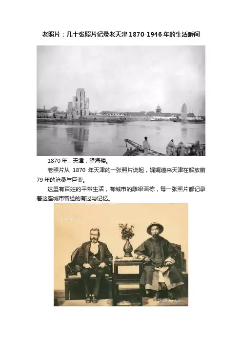
1921年,拆除同年重建后的老城中心鼓楼,建国初期拆除。现在的鼓楼为2001年建成。
1923年,天津,路边理发。
民国,天津东站。
1920年代,天津,意大利风情街马可波罗广场的罗马柱。这里不少小洋楼里住的都是中国近代史中的风云人物。
1920年代,ቤተ መጻሕፍቲ ባይዱ津,泰安道旧影。
1920年代初,天津东站第一站台(国际站台)接发由“满铁”转运经奉天驿(今沈阳站)开往北京的一列国际列车。
1900年,天津,金汤桥。坐落于海河之上,连接奥匈帝国租界与其他地方的通道。通过大型船舶时,中央可开启供船只通过。
1901年,天津,美国第六骑兵俘虏的义和团囚犯。
1902年10月1日,英军在老龙头车站(今天津站)降下英国国旗。
1902年10月1日,由英军占据的京榆铁路移交仪式在老龙头车站举行。
京榆铁路是指由北京至山海关的一段铁路的旧称,1900年,八国联军占据京榆铁路。
建于1903年的天津北站是津浦线、京山线交会处,也是津浦线的起点站。
时任直隶总督兼北洋大臣的袁世凯为摆脱老龙头火车站(今天津站)的租界管制而建天津北站。
天津,营口道与南京路交界处。照片大约拍摄于1936年。
1936年,天津码头,日本人装运走私和经济掠夺来的棉花。方大曾/摄。
1937年,日军占领天津火车站后欢呼。
1937年,在天津市街道上,一名日本兵展示受伤士兵的头盔。
1937年,日本士兵在中国天津街头。
1939年,天津,西开教堂前水灾场景。
1946年,天津,美国海军陆战队收养的中国孤儿。
民国时期,天津,压岁钱。
1900年,天津,战后,法租界被战争毁坏的建筑。
1900年,天津火车站附近,被八国联军毁坏的房屋。
#老上海影集#之静安寺路(2)
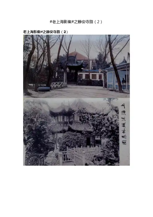
#老上海影集#之静安寺路(2)老上海影集#之静安寺路(2)11:愚园在静安寺路西首,赫德路(今常德路)8号,建于1890年,原是私家花园,也向公众开放,但收门票两角。
园内有假山、亭阁,是中西合璧的园林(图1、2)。
园林五易其主,曾以“夜公园”招来各路豪客。
1917年废弃。
当常州人刘葆良拥有愚园时,因没什么西洋名物可与张园竞争,曾蓄养猩猩、孔雀等动物吸引游客,但收效甚微。
后来,园主人不顾租界当局有关公共场所必须晚上12点前谢客关门的规定,园门洞开,开“夜公园”之先例。
“夜公园”曾一度在沪西流行,被道学先生斥为沪上陋风之最。
愚园路因愚园而得名。
图3为愚园内茶室。
12:1908年,静安寺路开通了有轨电车,马路蜕变成道路,从此加快了西区繁荣的进程。
图1:有轨电车驶过静安寺门前;图2:人力车在静安寺路上飞奔。
13:这两张是清末民初静安寺门前街景老照片,很是罕见。
现分享诸位朋友,让大家领略一下当年静安寺门前悠然惬意的安静。
14:英美租界工部局于清光绪二十四年(1898年)在静安寺对面(南京西路1649号)辟建静安寺公墓(又称外国坟山)。
公墓北靠南京西路,南接延安中路,东近常德路,西邻华山路,因静安古寺而得名。
1954年改建成静安公园。
图1:静安寺公墓大理石亭;图2:静安寺公墓的小教堂,1978年被拆除。
15:1929年,原戈登路(今江宁路)兼营舞厅“大华饭店”停业,以致上海西区没有一个与“贵族区”相称的娱乐场。
1931年,华商顾联承投资70万两白银,购置静安寺西北处(愚园路218号,图1)地皮建百乐门舞厅,次年建成。
百乐门全称是“百乐门大饭店舞厅”。
“百乐门”是英文“Paramount”译音,英文原义是“卓越”和“千变万化”的意思。
因建筑结构别致,舞厅装饰考究,当时有“远东第一乐府”之称。
百乐门由中国建筑师杨锡镠设计,陆根记营造厂承建。
建筑风格与大光明、大上海电影院有相似之处。
解放后,原舞厅主体建筑改为红都戏院,其他附属建筑则改建为商场。
ppt素材
TEXT
TEXT
Title
Add your text
ThemeGallery
is a Design Digital Content & Contents mall developed by Guild Design Inc.
ThemeGallery
is a Design Digital Content & Contents mall developed by Guild Design Inc.
TITLE
1. Content 2. Content 3. Content 4. Content 5. Content
TITLE
1. Content 2. Content 3. Content 4. Content 5. Content
TITLE
1. Content 2. Content 3. Content 4. Content 5. Content
58
eProcurement
Corporate Exchanges
Business to Business Commerce
3
ThemeGallery is a Design Digital Content & Contents mall developed by Guild Design Inc.
2001
2002
2003
2004
TEXT
TEXT
TEXT
TEXT
TEXT
TEXT
TEXT
TEXT
TITLE
1.CONTENTS Click to add text 2.CONTENTS Click to add text 3.CONTENTS Click to add text
老照片:1910年代的中国风貌

老照片: 1910年代的中国风貌
1907年,新疆叶尔羌的街头,人们三五成群,赌博成风。原载《老照片》第14辑。 20世纪初,昆明的清政府官员在衙门的天井里审理诉讼。原载《老照片》第16辑。
20世纪初,烟台的一间教会印刷所。劳作其间的孩子们,有幸成为当地最早掌握西方印刷技术 的一批中国人。原载《老照片》第19辑。
20世纪初,青岛一家洋车车行的景象。原载原载《老照片》第14辑。 1910年代,山东胶东的一个村庄雇请戏班来村里唱大戏的场面。原载《老照片》第12辑。
清末民初社会生活变迁PPT课件
居住变迁
传统建筑向现代建筑转变
传统的四合院、窑洞等逐渐被现代的楼房、公寓所取代。
居住条件的变化
传统的拥挤、简陋的居住条件逐渐得到改善,人们开始追求宽敞、 舒适的居住环境。
家居陈设的变化
传统的家居陈设以实用为主,现代家居陈设则更注重美观和舒适, 如沙发、地毯、窗帘等。
交通与通讯变迁
1 2 3
交通工具的变化
80%
居住条件改善
城市里出现了新式住宅,农村中 也开始出现新式农舍,居住条件 得到一定程度的改善。
对家庭生活的影响
家庭结构变化
传统的大家庭逐渐解体,小家 庭成为主流,家庭成员之间的 关系也发生了变化。
家庭生活内容变化
家庭娱乐活动增多,如看电影 、听戏等,家庭成员之间的互 动和交流也更加频繁。
家庭观念变化
文化背景
清朝末期封建文化占据主导地 位,思想保守落后。
民国初期新文化运动兴起,提 倡民主、科学、自由等思想观 念。
西方文化大量涌入中国,对中 国传统文化产生冲击和影响。
03
社会生活变迁的表现
服饰变迁
传统服饰向现代服饰转变
长袍马褂逐渐被西装、中山装等现代服饰所取代。
服饰材料的变化
传统的丝绸、棉麻逐渐被现代纺织品所取代,如洋 布、洋纱等。
辛亥革命推翻了清朝统治,建立了中华民国,实现 了政治体制的变革。
民国初期政治不稳定,军阀割据,政治斗争激烈。
经济背景
02
01
03
清朝末期经济落后,以小农经济为主,工业基础薄弱 。
民国初期民族资本主义得到发展,轻工业和纺织业等 产业逐渐兴起。
随着西方列强的侵略和资本输出,中国经济受到严重 冲击和影响。
对文化传承的影响
一幅清末民初保定社会生活的历史图卷——记王宗玺拍摄的一组老照片
保 定 电灯有 限公 司这两 大民营企业 为
图一 民国初年 的保定 火车站
最。 这两家企业 的筹建和发展 , 都与当时 保定商会会长樊榕有密切关系。 樊榕 (8 1 92年 )字荫荪 , 16 —14 , 号 退安 , 河北清苑人。他是光绪癸 巳(83 19 年) 举人, 山西知县 。民国后秉承实业 授
隶 ”1 [ 4 。
在樊达汇 、樊榕父子两代人的努力
之下 ,( ) “ 樊 家大饶裕 , 遂创设商会于保
定, 广建学堂 , 与开四民之智 , 国家利 凡
图四 保 定 城 外 运 河 一景
用厚生诸事 , 出巨资助之成立”。 屡 樊达
一
7 —
维普资讯
王宗玺 (80— 93年 )字尊信 , 19 14 , 辽宁 海城人 , 清光绪朝兵部右侍郎王英楷之子。 王
英楷 ,海城县志》 《 有传 , 家住当时的保定城关 后卫街¨ I 。王宗玺 11 年出任北洋政府航空 96 署总工程师 ,是中国第一个设计三引擎飞机
华兵工厂帮办 ,是一位军事工程技术专家【 2 1 。 由于工作需要 , 他又兼工摄影 , 这些照片就是
地, 是北方政治 、 军事 、 经济 、 文化中心 , 也是
南北交通的枢纽。 袁世凯主政以后 , 为筹集军
资、 练兵 , 不断扩大保定火车站的规模 , 使火 车站成为各种军事物资的集散地 。照片反映
余张,内容涉及清末民初河北保定社会生活
的方方面面 , 包括火车站 、 城外运河码头 、 城
的专家 ;9 5 , 12 年 应孙传方邀请 , 出任上海龙 六十万 , 口密集 , 人 市场也开始繁荣起来。码
他在工作之余拍摄的。下面挑选其中有代表 性的介绍如下 , 供河北学术界研究参考 。
民国时期,北平的街景和普通百姓的生活剪影(1931年-1934年)
民国时期,北平的街景和普通百姓的生活剪影(1931年-1934年)本组图片拍摄于1931年至1934年间,有北平的街道景观,也有忙忙碌碌的百姓身影,通过这些珍贵的老照片,可以使我们更加直观地了解上世纪三十年代早期北平的真实状况。
三十年代的五牌楼五牌楼位于正阳门外护城河上的一座正阳桥边,旧时传统有在桥头两端竖立牌楼的习惯,俗称“桥牌楼”。
正阳桥位于中轴线的最北端,是京城九门护城河桥中最大的一座。
四十年代的五牌楼40年代的正阳桥牌楼,和上一张图对比会发现有很大的变化,牌楼经过修缮,上面的满文不见了,原来的汽灯也已换成电灯,两辆洋车正鱼贯而过。
远处可以看到不少骑着自行车的人,说明当时在北京街头自行车已是寻常物了。
街头的行人和车辆基本都是遵照左行的原则。
北平街头的手推车中国传统的手推独轮车,在各地有不同的称谓,且根据各地的道路不同稍有变动,比如四川成都平原地区称之为“鸡公车”,但轮子较小。
这种车辆的历史已非常悠久,因为只有一个轮子的原因,对路况的要求很低,窄道、小巷、田埂和小桥都畅通无阻。
礼仪伞在旧时北京街头经常可以看到这样一类人,手持各种礼器,在接亲或葬礼的队列中充当礼仪仪仗,他们有一个专门的名称叫执事。
图为一名执事扛着收起的礼仪伞走在路上,这种伞是京城红白喜事时经常可以看到的礼器,做工精良,上面绣有精美的纹饰。
香烟摊店铺门口摆着八仙桌和长条凳,桌子后面站着一位摆卖香烟的老者,非常富态。
他穿着蓝色的坎肩,头顶瓜皮帽,他售卖纸烟,自己抽的却是旱烟袋。
拾荒一名中年妇人背着柳条篓经过,篓子里装着她拾荒捡到的纸屑。
街边处开着一家茶叶店,门上有“诸品各茶”的字样,茶叶店门前停放着洋车。
两个乞丐依靠在墙边的两个乞丐,不知是不是兄弟俩。
大男孩手里提着铁皮桶,脚下的鞋子露着脚趾头,小男孩站在旁边,所谓的裤子只剩下了几缕破布,用麻绳吊在腰间。
崇文门外大街崇文门是旧时北京内城南垣东门,城门建成于明永乐十九年(1421年)。
ASTM D638_2003
Designation:D638–03Standard Test Method forTensile Properties of Plastics1This standard is issued under thefixed designation D638;the number immediately following the designation indicates the year of original adoption or,in the case of revision,the year of last revision.A number in parentheses indicates the year of last reapproval.A superscript epsilon(e)indicates an editorial change since the last revision or reapproval.This standard has been approved for use by agencies of the Department of Defense.1.Scope*1.1This test method covers the determination of the tensile properties of unreinforced and reinforced plastics in the form of standard dumbbell-shaped test specimens when tested under defined conditions of pretreatment,temperature,humidity,and testing machine speed.1.2This test method can be used for testing materials of any thickness up to14mm[0.55in.].However,for testing specimens in the form of thin sheeting,includingfilm less than 1.0mm[0.04in.]in thickness,Test Methods D882is the preferred test method.Materials with a thickness greater than 14mm[0.55in.]must be reduced by machining.1.3This test method includes the option of determining Poisson’s ratio at room temperature.N OTE1—This test method and ISO527-1are technically equivalent. N OTE2—This test method is not intended to cover precise physical procedures.It is recognized that the constant rate of crosshead movement type of test leaves much to be desired from a theoretical standpoint,that wide differences may exist between rate of crosshead movement and rate of strain between gage marks on the specimen,and that the testing speeds specified disguise important effects characteristic of materials in the plastic state.Further,it is realized that variations in the thicknesses of test specimens,which are permitted by these procedures,produce variations in the surface-volume ratios of such specimens,and that these variations may influence the test results.Hence,where directly comparable results are desired,all samples should be of equal thickness.Special additional tests should be used where more precise physical data are needed.N OTE3—This test method may be used for testing phenolic molded resin or laminated materials.However,where these materials are used as electrical insulation,such materials should be tested in accordance with Test Methods D229and Test Method D651.N OTE4—For tensile properties of resin-matrix composites reinforced with oriented continuous or discontinuous high modulus>20-GPa [>3.03106-psi]fibers,tests shall be made in accordance with Test Method D3039/D3039M.1.4Test data obtained by this test method are relevant and appropriate for use in engineering design.1.5The values stated in SI units are to be regarded as the standard.The values given in brackets are for information only.1.6This standard does not purport to address all of the safety concerns,if any,associated with its use.It is the responsibility of the user of this standard to establish appro-priate safety and health practices and determine the applica-bility of regulatory limitations prior to use.2.Referenced Documents2.1ASTM Standards:2D229Test Methods for Rigid Sheet and Plate Materials Used for Electrical InsulationD412Test Methods for Vulcanized Rubber and Thermo-plastic Elastomers—TensionD618Practice for Conditioning Plastics for TestingD651Test Method for Tensile Strength of Molded Electri-cal Insulating MaterialsD882Test Methods for Tensile Properties of Thin Plastic SheetingD883Terminology Relating to PlasticsD1822Test Method for Tensile-Impact Energy to Break Plastics and Electrical Insulating MaterialsD3039/D3039M Test Method for Tensile Properties of Polymer Matrix Composite MaterialsD4000Classification System for Specifying Plastic Mate-rialsD4066Classification System for Nylon Injection and Ex-trusion MaterialsD5947Test Methods for Physical Dimensions of Solid Plastic SpecimensE4Practices for Force Verification of Testing Machines E83Practice for Verification and Classification of Exten-someterE132Test Method for Poisson’s Ratio at Room Tempera-tureE691Practice for Conducting an Interlaboratory Study to Determine the Precision of a Test Method2.2ISO Standard:31This test method is under the jurisdiction of ASTM Committee D20on Plastics and is the direct responsibility of Subcommittee D20.10on Mechanical Properties.Current edition approved December1,2003.Published January2004.Originally approved st previous edition approved in2002as D638-02a.2For referenced ASTM standards,visit the ASTM website,,or contact ASTM Customer Service at service@.For Annual Book of ASTM Standards volume information,refer to the standard’s Document Summary page on the ASTM website.3Available from American National Standards Institute(ANSI),25W.43rd St., 4th Floor,New York,NY10036.1*A Summary of Changes section appears at the end of this standard.Copyright©ASTM International,100Barr Harbor Drive,PO Box C700,West Conshohocken,PA19428-2959,United States.Copyright ASTM InternationalReproduced by IHS under license with ASTMNot for ResaleNo reproduction or networking permitted without license from IHS--``,```-`-`,,`,,`,`,,`---ISO527-1Determination of Tensile Properties3.Terminology3.1Definitions—Definitions of terms applying to this test method appear in Terminology D883and Annex A2.4.Significance and Use4.1This test method is designed to produce tensile property data for the control and specification of plastic materials.These data are also useful for qualitative characterization and for research and development.For many materials,there may be a specification that requires the use of this test method,but with some procedural modifications that take precedence when adhering to the specification.Therefore,it is advisable to refer to that material specification before using this test method. Table1in Classification D4000lists the ASTM materials standards that currently exist.4.2Tensile properties may vary with specimen preparation and with speed and environment of testing.Consequently, where precise comparative results are desired,these factors must be carefully controlled.4.2.1It is realized that a material cannot be tested without also testing the method of preparation of that material.Hence, when comparative tests of materials per se are desired,the greatest care must be exercised to ensure that all samples are prepared in exactly the same way,unless the test is to include the effects of sample preparation.Similarly,for referee pur-poses or comparisons within any given series of specimens, care must be taken to secure the maximum degree of unifor-mity in details of preparation,treatment,and handling.4.3Tensile properties may provide useful data for plastics engineering design purposes.However,because of the high degree of sensitivity exhibited by many plastics to rate of straining and environmental conditions,data obtained by this test method cannot be considered valid for applications involv-ing load-time scales or environments widely different from those of this test method.In cases of such dissimilarity,no reliable estimation of the limit of usefulness can be made for most plastics.This sensitivity to rate of straining and environ-ment necessitates testing over a broad load-time scale(includ-ing impact and creep)and range of environmental conditions if tensile properties are to suffice for engineering design pur-poses.N OTE5—Since the existence of a true elastic limit in plastics(as in many other organic materials and in many metals)is debatable,the propriety of applying the term“elastic modulus”in its quoted,generally accepted definition to describe the“stiffness”or“rigidity”of a plastic has been seriously questioned.The exact stress-strain characteristics of plastic materials are highly dependent on such factors as rate of application of stress,temperature,previous history of specimen,etc.However,stress-strain curves for plastics,determined as described in this test method, almost always show a linear region at low stresses,and a straight line drawn tangent to this portion of the curve permits calculation of an elastic modulus of the usually defined type.Such a constant is useful if its arbitrary nature and dependence on time,temperature,and similar factors are realized.4.4Poisson’s Ratio—When uniaxial tensile force is applied to a solid,the solid stretches in the direction of the applied force(axially),but it also contracts in both dimensions lateral to the applied force.If the solid is homogeneous and isotropic,and the material remains elastic under the action of theapplied force,the lateral strain bears a constant relationship to the axial strain.This constant,called Poisson’s ratio,is defined as the negative ratio of the transverse(negative)to axial strain under uniaxial stress.4.4.1Poisson’s ratio is used for the design of structures in which all dimensional changes resulting from the application of force need to be taken into account and in the application of the generalized theory of elasticity to structural analysis.N OTE6—The accuracy of the determination of Poisson’s ratio is usually limited by the accuracy of the transverse strain measurements because the percentage errors in these measurements are usually greater than in the axial strain measurements.Since a ratio rather than an absolute quantity is measured,it is only necessary to know accurately the relative value of the calibration factors of the extensometers.Also,in general,the value of the applied loads need not be known accurately.5.Apparatus5.1Testing Machine—A testing machine of the constant-rate-of-crosshead-movement type and comprising essentially the following:5.1.1Fixed Member—Afixed or essentially stationary member carrying one grip.5.1.2Movable Member—A movable member carrying a second grip.5.1.3Grips—Grips for holding the test specimen between thefixed member and the movable member of the testing machine can be either thefixed or self-aligning type.5.1.3.1Fixed grips are rigidly attached to thefixed and movable members of the testing machine.When this type of grip is used extreme care should be taken to ensure that the test specimen is inserted and clamped so that the long axis of the test specimen coincides with the direction of pull through the center line of the grip assembly.5.1.3.2Self-aligning grips are attached to thefixed and movable members of the testing machine in such a manner that they will move freely into alignment as soon as any load is applied so that the long axis of the test specimen will coincide with the direction of the applied pull through the center line of the grip assembly.The specimens should be aligned as per-fectly as possible with the direction of pull so that no rotary motion that may induce slippage will occur in the grips;there is a limit to the amount of misalignment self-aligning grips will accommodate.5.1.3.3The test specimen shall be held in such a way that slippage relative to the grips is prevented insofar as possible. Grip surfaces that are deeply scored or serrated with a pattern similar to those of a coarse single-cutfile,serrations about2.4 mm[0.09in.]apart and about1.6mm[0.06in.]deep,have been found satisfactory for most thermoplastics.Finer serra-tions have been found to be more satisfactory for harder plastics,such as the thermosetting materials.The serrations should be kept clean and sharp.Breaking in the grips may occur at times,even when deep serrations or abraded specimen surfaces are used;other techniques must be used in these cases. Other techniques that have been found useful,particularly with smooth-faced grips,are abrading that portion of the surface of the specimen that will be in the grips,and interposing thinpieces of abrasive cloth,abrasive paper,or plastic,or rubber-coated fabric,commonly called hospital sheeting,between the specimen and the grip surface.No.80double-sided abrasive paper has been found effective in many cases.An open-mesh fabric,in which the threads are coated with abrasive,has also been effective.Reducing the cross-sectional area of the speci-men may also be effective.The use of special types of grips is sometimes necessary to eliminate slippage and breakage in the grips.5.1.4Drive Mechanism—A drive mechanism for imparting to the movable member a uniform,controlled velocity with respect to the stationary member,with this velocity to be regulated as specified in Section8.5.1.5Load Indicator—A suitable load-indicating mecha-nism capable of showing the total tensile load carried by the test specimen when held by the grips.This mechanism shall be essentially free of inertia lag at the specified rate of testing and shall indicate the load with an accuracy of61%of the indicated value,or better.The accuracy of the testing machine shall be verified in accordance with Practices E4.N OTE7—Experience has shown that many testing machines now in use are incapable of maintaining accuracy for as long as the periods between inspection recommended in Practices E4.Hence,it is recommended that each machine be studied individually and verified as often as may be found necessary.It frequently will be necessary to perform this function daily.5.1.6Thefixed member,movable member,drive mecha-nism,and grips shall be constructed of such materials and in such proportions that the total elastic longitudinal strain of the system constituted by these parts does not exceed1%of the total longitudinal strain between the two gage marks on the test specimen at any time during the test and at any load up to the rated capacity of the machine.5.1.7Crosshead Extension Indicator—A suitable extension indicating mechanism capable of showing the amount of change in the separation of the grips,that is,crosshead movement.This mechanism shall be essentially free of inertial lag at the specified rate of testing and shall indicate the crosshead movement with an accuracy of610%of the indicated value.5.2Extension Indicator(extensometer)—A suitable instru-ment shall be used for determining the distance between two designated points within the gage length of the test specimen as the specimen is stretched.For referee purposes,the extensom-eter must be set at the full gage length of the specimen,as shown in Fig.1.It is desirable,but not essential,that this instrument automatically record this distance,or any change in it,as a function of the load on the test specimen or of the elapsed time from the start of the test,or both.If only the latter is obtained,load-time data must also be taken.This instrument shall be essentially free of inertia at the specified speed of testing.Extensometers shall be classified and their calibration periodically verified in accordance with Practice E83.5.2.1Modulus-of-Elasticity Measurements—For modulus-of-elasticity measurements,an extensometer with a maximum strain error of0.0002mm/mm[in./in.]that automatically and continuously records shall be used.An extensometer classified by Practice E83as fulfilling the requirements of a B-2classification within the range of use for modulusmeasure-ments meets this requirement.5.2.2Low-Extension Measurements—For elongation-at-yield and low-extension measurements(nominally20%or less),the same above extensometer,attenuated to20%exten-sion,may be used.In any case,the extensometer system must meet at least Class C(Practice E83)requirements,which include afixed strain error of0.001strain or61.0%of the indicated strain,whichever is greater.5.2.3High-Extension Measurements—For making mea-surements at elongations greater than20%,measuring tech-niques with error no greater than610%of the measured value are acceptable.5.2.4Poisson’s Ratio—Bi-axial extensometer or axial and transverse extensometers capable of recording axial strain and transverse strain simultaneously.The extensometers shall be capable of measuring the change in strains with an accuracy of 1%of the relevant value or better.N OTE8—Strain gages can be used as an alternative method to measure axial and transverse strain;however,proper techniques for mounting strain gages are crucial to obtaining accurate data.Consult strain gage suppliers for instruction and training in these special techniques.5.3Micrometers—Apparatus for measuring the width and thickness of the test specimen shall comply with the require-ments of Test Method D5947.6.Test Specimens6.1Sheet,Plate,and Molded Plastics:6.1.1Rigid and Semirigid Plastics—The test specimen shall conform to the dimensions shown in Fig. 1.The Type I specimen is the preferred specimen and shall be used where sufficient material having a thickness of7mm[0.28in.]or less is available.The Type II specimen may be used when a material does not break in the narrow section with the preferred Type I specimen.The Type V specimen shall be used where only limited material having a thickness of4mm[0.16in.]or less is available for evaluation,or where a large number of specimens are to be exposed in a limited space(thermal and environmental stability tests,etc.).The Type IV specimen should be used when direct comparisons are required between materials in different rigidity cases(that is,nonrigid and semirigid).The Type III specimen must be used for all materials with a thickness of greater than7mm[0.28in.]but not more than14mm[0.55in.].6.1.2Nonrigid Plastics—The test specimen shall conform to the dimensions shown in Fig.1.The Type IV specimen shall be used for testing nonrigid plastics with a thickness of4mm [0.16in.]or less.The Type III specimen must be used for all materials with a thickness greater than7mm[0.28in.]but not more than14mm[0.55in.].6.1.3Reinforced Composites—The test specimen for rein-forced composites,including highly orthotropic laminates, shall conform to the dimensions of the Type I specimen shown in Fig.1.6.1.4Preparation—Test specimens shall be prepared by machining operations,or die cutting,from materials in sheet, plate,slab,or similar form.Materials thicker than14mm[0.55F For molded specimens,a draft of not over0.13mm[0.005in.]may be allowed for either Type I or II specimens3.2mm[0.13in.]in thickness,and this should be taken into account when calculating width of the specimen.Thus a typical section of a molded Type I specimen,having the maximum allowable draft,could be as follows:G Overall widths greater than the minimum indicated may be desirable for some materials in order to avoid breaking in the grips.H Overall lengths greater than the minimum indicated may be desirable either to avoid breaking in the grips or to satisfy special test requirements.I Test marks or initial extensometer span.J When self-tightening grips are used,for highly extensible polymers,the distance between grips will depend upon the types of grips used and may not be critical if maintained uniform once chosen.FIG.1Tension Test Specimens for Sheet,Plate,and Molded Plasticsin.]must be machined to 14mm [0.55in.]for use as Type III specimens.Specimens can also be prepared by molding the material to be tested.N OTE 9—Test results have shown that for some materials such as glasscloth,SMC,and BMC laminates,other specimen types shouldbe considered to ensure breakage within the gage length of the specimen,as mandated by 7.3.N OTE 10—When preparing specimens from certain composite lami-nates such as woven roving,or glass cloth,care must be exercised in cutting the specimens parallel to the reinforcement.The reinforcement will be significantly weakened by cutting on a bias,resulting in lower laminate properties,unless testing of specimens in a direction other than parallel with the reinforcement constitutes a variable being studied.N OTE 11—Specimens prepared by injection molding may have different tensile properties than specimens prepared by machining or die-cutting because of the orientation induced.This effect may be more pronounced in specimens with narrow sections.6.2Rigid Tubes —The test specimen for rigid tubes shall be as shown in Fig.2.The length,L ,shall be as shown in the table in Fig.2.A groove shall be machined around the outside of the specimen at the center of its length so that the wall section after machining shall be 60%of the original nominal wall thick-ness.This groove shall consist of a straight section 57.2mm [2.25in.]in length with a radius of 76mm [3in.]at each end joining it to the outside diameter.Steel or brass plugs having diameters such that they will fit snugly inside the tube and having a length equal to the full jaw length plus 25mm [1in.]shall be placed in the ends of the specimens to prevent crushing.They can be located conveniently in the tube by separating and supporting them on a threaded metal rod.Details of plugs and test assembly are shown in Fig.2.6.3Rigid Rods —The test specimen for rigid rods shall be as shown in Fig.3.The length,L ,shall be as shown in the table in Fig.3.A groove shall be machined around the specimen at the center of its length so that the diameter of the machined portion shall be 60%of the original nominal diameter.This groove shall consist of a straight section 57.2mm [2.25in.]in length with a radius of 76mm [3in.]at each end joining it to the outside diameter.6.4All surfaces of the specimen shall be free of visible flaws,scratches,or imperfections.Marks left by coarse ma-chining operations shall be carefully removed with a fine file or abrasive,and the filed surfaces shall then be smoothed with abrasive paper (No.00or finer).The finishing sanding strokes shall be made in a direction parallel to the long axis of the test specimen.All flash shall be removed from a molded specimen,taking great care not to disturb the molded surfaces.In machining a specimen,undercuts that would exceed the dimensional tolerances shown in Fig.1shall be scrupulously avoided.Care shall also be taken to avoid other common machining errors.6.5If it is necessary to place gage marks on the specimen,this shall be done with a wax crayon or India ink that will not affect the material being tested.Gage marks shall not be scratched,punched,or impressed on the specimen.6.6When testing materials that are suspected of anisotropy,duplicate sets of test specimens shall be prepared,having their long axes respectively parallel with,and normal to,the suspected direction of anisotropy.7.Number of Test Specimens7.1Test at least five specimens for each sample in the case of isotropic materials.DIMENSIONS OF TUBE SPECIMENSNominal Wall ThicknessLength of Radial Sections,2R.S.Total CalculatedMinimum Length of SpecimenStandard Length,L ,of Specimen to Be Used for 89-mm [3.5-in.]Jaws Amm [in.]0.79[1⁄32]13.9[0.547]350[13.80]381[15]1.2[3⁄64]17.0[0.670]354[13.92]381[15]1.6[1⁄16]19.6[0.773]356[14.02]381[15]2.4[3⁄32]24.0[0.946]361[14.20]381[15]3.2[1⁄8]27.7[1.091]364[14.34]381[15]4.8[3⁄16]33.9[1.333]370[14.58]381[15]6.4[1⁄4]39.0[1.536]376[14.79]400[15.75]7.9[5⁄16]43.5[1.714]380[14.96]400[15.75]9.5[3⁄8]47.6[1.873]384[15.12]400[15.75]11.1[7⁄16]51.3[2.019]388[15.27]400[15.75]12.7[1⁄2]54.7[2.154]391[15.40]419[16.5]AFor other jaws greater than 89mm [3.5in.],the standard length shall be increased by twice the length of the jaws minus 178mm [7in.].The standard length permits a slippage of approximately 6.4to 12.7mm [0.25to 0.50in.]in each jaw while maintaining the maximum length of the jaw grip.FIG.2Diagram Showing Location of Tube Tension TestSpecimens in Testing Machine7.2Test ten specimens,five normal to,and five parallel with,the principle axis of anisotropy,for each sample in the case of anisotropic materials.7.3Discard specimens that break at some flaw,or that break outside of the narrow cross-sectional test section (Fig.1,dimension “L”),and make retests,unless such flaws constitute a variable to be studied.DIMENSIONS OF ROD SPECIMENSNominal Diam-eter Length of RadialSections,2R.S.Total CalculatedMinimumLength of SpecimenStandard Length,L ,ofSpecimen to Be Usedfor 89-mm [31⁄2-in.]Jaws A mm [in.]3.2[1⁄8]19.6[0.773]356[14.02]381[15]4.7[1⁄16]24.0[0.946]361[14.20]381[15]6.4[1⁄4]27.7[1.091]364[14.34]381[15]9.5[3⁄8]33.9[1.333]370[14.58]381[15]12.7[1⁄2]39.0[1.536]376[14.79]400[15.75]15.9[5⁄8]43.5[1.714]380[14.96]400[15.75]19.0[3⁄4]47.6[1.873]384[15.12]400[15.75]22.2[7⁄8]51.5[2.019]388[15.27]400[15.75]25.4[1]54.7[2.154]391[15.40]419[16.5]31.8[11⁄4]60.9[2.398]398[15.65]419[16.5]38.1[11⁄2]66.4[2.615]403[15.87]419[16.5]42.5[13⁄4]71.4[2.812]408[16.06]419[16.5]50.8[2]76.0[2.993]412[16.24]432[17]AFor other jaws greater than 89mm [3.5in.],the standard length shall be increased by twice the length of the jaws minus 178mm [7in.].The standard length permits a slippage of approximately 6.4to 12.7mm [0.25to 0.50in.]in each jaw while maintaining the maximum length of the jaw grip.FIG.3Diagram Showing Location of Rod Tension Test Specimenin Testing MachineASelect the lowest speed that produces rupture in 1⁄2to 5min for the specimen geometry being used (see 8.2).BSee Terminology D 883for definitions.CThe initial rate of straining cannot be calculated exactly for dumbbell-shaped specimens because of extension,both in the reduced section outside the gage length and in the fillets.This initial strain rate can be measured from the initial slope of the tensile strain-versus-time diagram.10.Procedure10.1Measure the width and thickness of each specimen to the nearest 0.025mm [0.001in.]using the applicable test methods in D 5947.10.1.1Measure the width and thickness of flat specimens at the center of each specimen and within 5mm of each end of the gage length.10.1.2Injection molded specimen dimensions may be de-termined by actual measurement of only one specimen from each sample when it has previously been demonstrated that the specimen-to-specimen variation in width and thickness is less than 1%.10.1.3Take the width of specimens produced by a Type IV die as the distance between the cutting edges of the die in the narrow section.10.1.4Measure the diameter of rod specimens,and the inside and outside diameters of tube specimens,to the nearest 0.025mm [0.001in.]at a minimum of two points 90°apart;make these measurements along the groove for specimens so e plugs in testing tube specimens,as shown in Fig.2.10.2Place the specimen in the grips of the testing machine,taking care to align the long axis of the specimen and the grips with an imaginary line joining the points of attachment of the grips to the machine.The distance between the ends of the gripping surfaces,when using flat specimens,shall be as indicated in Fig.1.On tube and rod specimens,the location for the grips shall be as shown in Fig.2and Fig.3.Tighten the grips evenly and firmly to the degree necessary to prevent slippage of the specimen during the test,but not to the point where the specimen would be crushed.10.3Attach the extension indicator.When modulus is being determined,a Class B-2or better extensometer is required (see 5.2.1).N OTE 13—Modulus of materials is determined from the slope of the linear portion of the stress-strain curve.For most plastics,this linear portion is very small,occurs very rapidly,and must be recorded automati-cally.The change in jaw separation is never to be used for calculating modulus or elongation.10.3.1Poisson’s Ratio Determination:10.3.1.1The measurement of Poisson’s Ratio is optional and need be determined only when requested.If the tensile modulus is determined at a test speed of 5mm/min,it is acceptable to determine the Poisson’s ratio at the same time as the tensile modulus.10.3.1.2Poisson’s Ratio shall be determined at a speed of 5mm/min.For materials having a distinct linear elastic region on the stress-strain curve the ratio shall be determined in the same load range as that used for the measurement of the modulus of10.6Record the load and extension at the yield point (if one exists)and the load and extension at the moment of rupture.N OTE 15—If it is desired to measure both modulus and failure proper-ties (yield or break,or both),it may be necessary,in the case of highly extensible materials,to run two independent tests.The high magnification extensometer normally used to determine properties up to the yield point may not be suitable for tests involving high extensibility.If allowed to remain attached to the specimen,the extensometer could be permanently damaged.A broad-range incremental extensometer or hand-rule technique may be needed when such materials are taken to rupture.11.Calculation11.1Toe compensation shall be made in accordance with Annex A1,unless it can be shown that the toe region of the curve is not due to the take-up of slack,seating of the specimen,or other artifact,but rather is an authentic material response.TABLE 2Modulus,106psi,for Eight Laboratories,Five MaterialsMeanS r S R I r I R Polypropylene0.2100.00890.0710.0250.201Cellulose acetate butyrate 0.2460.01790.0350.0510.144Acrylic0.4810.01790.0630.0510.144Glass-reinforced nylon 1.170.05370.2170.1520.614Glass-reinforced polyester1.390.08940.2660.2530.753。