浮动式球阀说明书
100X型浮球阀说明书
尊敬的用户:感谢您选用我公司的产品!该使用说明书应传递终端用户。
在使用本产品之前请您详细阅读本说明书,让您感受到操作的方便、使用的愉快。
下道工序是我们对您永恒的真诚服务!说明书100X型浮球阀说明书产品介绍:100X隔膜式电动遥控浮球阀是沪航阀门开发生产的一种兼具多种功能的控制水池液位的水力控制阀。
100X隔膜式遥控浮球阀主要安装于水池或高架水塔的进水口处,当水位达到设定的高度时,主阀由浮球导阀控制关闭进水口停止供水;当水位下降后,主阀由浮球开关控制打开进水口向水池注水,实现自动补水。
液位控制精确,不受水压干扰;100X隔膜式遥控浮球阀可随水池的高度及使用空间任意位置安装,维护、调试、检查方便、密封可靠,使用寿命长。
100X隔膜式遥控浮球阀性能可靠、强度高、动作灵敏灵活适用于450mm口径以下的管道。
DN500mm口径以上的建议使用活塞式。
应用范围:城建、化工、冶金、石油、制药、食品、饮料、环保工作原理:100X遥控浮球阀利用管道上游的水压推动阀瓣上升,开启阀门,向水池供水;当水池液面到达所需高度时,浮球在浮力的作用下上升,从而关闭阀门,截断管道向水池的排放。
当水池排放掉水时,浮球下落,开通上腔的流通,此时,上游的压力又使阀瓣上升,开启阀门,使管道继续向水池供水。
遥控浮球阀,浮球动作迅速,液位控制准确度高,灵活耐用,水位不受水压干扰且关闭紧密不漏水。
遥控浮球阀主要安装在高层建筑水塔、水池的进水管道上。
结构特点:100X隔膜式遥控浮球阀性能可靠、强度高、动作灵敏灵活,液位控制精确,不受水压干扰,可随水池的高度及使用空间任意位置安装,维护、调试、检查方便、密封可靠,使用寿命长。
◆结构新颖合理、合理运用液压原理控制论◆工作平稳可靠、流量大◆阀瓣快开慢闭、无水锤冲击(关闭时间可调)◆止回密封效果好、使用寿命时间长◆安装维修方便标准规范:产品设计执行:CJ/T160-2002结构长度标准:GB/T12221-2005连接法兰标准:GB/T17241.6-1998压力温度等级:GB/T12224-2005铁制和铜制球阀:GB/T15185-94试验检验标准:GB/T 13927阀门的标志和涂漆符合JB/T 106-2004零件材料与工况:10 调节杆不锈钢主要技术参数公称压力pn试验压力(Mpa)适用介质适宜介质温度壳体密封10 1.5 1.1无杂物的清水、污水≤80℃16 2.4 1.7625 4.0 2.75 主要外形尺寸:公称尺寸DN尺寸(mm)L W1 W H1 H F20 150 130 325 179 212 116 25 160 130 325 179 212 116 32 180 130 325 179 212 116 40 200 140 335 210 265 168 50 203 140 335 210 265 168 65 216 140 335 215 310 180 80 241 145 345 245 350 210 100 292 155 365 305 460 284 125 330 165 385 365 520 310 150 356 180 410 415 570 370 200 495 205 465 510 840 463 250 622 225 505 560 890 525 300 698 245 545 658 1030 625 350 787 275 595 696 1090 705安装调试:A、安装要求:1、在安装本阀前,应将管道冲洗干净,可视水质情况一年保养一至二次。
自由浮球式蒸汽疏水阀使用说明书
35CrMoA 45
2. 排量数据/ Displacement data
口径/ Caliber 压力/ Pressure
MPa 0.15 0.25 0.4 0.6 1.0 1.6
15~25 B
1110 1000 950 810 660 550
25~50 D
5460 5350 4700 3590 3190 2740
高 , 密 封 性 能 好 / This series of products using the float traps all through advanced grinding process, float high precision, good sealing performance 4、排空气性能好/ Row air performance is good 自动自由浮球疏水阀能自动排除不凝结的冷、热气体,有效防止气锁现象/ Automatic free float steam traps automatically exclude condensation of cold and
使用说明书/Explain
CS41H 系列/Series CS11H 系列/Series 自由浮球/自动自由浮球卧式
Free Float / Auto Horizontal free float
自由浮球立式蒸汽疏水阀
Vertical free float steam trap
安装维修指南
Installation and maintenance guide
/ Automatic free float, free float-type traps can be used for steam heating equipment and condensate recovery system and the need to quickly rule out the condensation of water conditions, so that the steam pipe heating equipment systems and recovery of condensate and remove to gain high heating efficiency, energy conservation a significant effect. Widely used in chemical, oil refining, electric power, textile, pharmaceutical, paper and so on need to condition the steam heating business, especially for low pressure, displacement of large and higher temperature stability, should not lag depositors condensate system is more suitable equipment. 二、结构特点和工作原理/ Structural characteristics and working principle 1、能连续排放饱和水和凝结水/ To a continuous discharge of saturated water
浮动球阀使用说明书
浮动球阀使用说明书一、概述浮动球阀是一种常用于管道系统中的阀门,其特点是具有流体控制性能优良,并且操作简便可靠。
本文档将为您提供对浮动球阀的详细了解和正确使用的指导。
二、浮动球阀的组成和工作原理1.构造组成:浮动球阀主要由阀体、阀盖、阀球、阀杆、密封圈等部件组成。
2.工作原理:当阀门处于关闭状态时,阀球被压力推向阀座以达到密封效果。
当需要开启阀门时,旋转阀杆使阀球离开阀座,从而形成通路,流体得以通过。
三、浮动球阀的主要特点1.流体控制性能好:浮动球阀采用浮动式的设计,阀球可以自由浮动,使得流体通过阀门时的阻力很小,且封闭效果好。
2.使用范围广:浮动球阀适用于液体、气体等流体介质的控制,广泛应用于石油化工、冶金、电力、轻纺、造纸等工业领域。
3.操作灵活简便:浮动球阀采用旋转操作方式,操作简单方便,不需要大力气即可完成开关动作。
4.可靠性高:浮动球阀的密封性能好,耐腐蚀性能强,寿命长,使用可靠。
四、浮动球阀的安装和使用注意事项1.安装要点:(1)确保管道系统的清洁,避免杂物以及异物进入阀门内部。
(2)安装前应检查阀门的各个部位是否完好,阀杆是否与阀球灵活连接。
(3)根据管道系统的要求,选择合适的规格和型号的浮动球阀。
2.使用要点:(1)在使用前,应检查阀门的密封性能,确保阀球与阀座之间的接触紧密。
(2)在使用过程中,避免过大的压力冲击和温度变化,以免影响阀门的正常工作。
(3)定期对浮动球阀进行维护保养,包括清洁、润滑、紧固等。
五、浮动球阀故障处理1.漏气或漏液:(1)检查阀球与阀座之间是否存在磨损,必要时更换阀球或阀座。
(2)检查密封圈是否破损,如有必要,进行更换。
2.开关不灵活:(1)检查阀杆与阀球之间的连接,如有松动应进行紧固。
(2)检查阀杆是否存在异物,清理阀杆上的污物。
六、浮动球阀的保养和维护1.定期清洁:使用过程中,阀门内部可能会沉积污物,定期清洁可以保证阀门的正常运行。
2.润滑:定期给阀门的各个活动部位添加适量的润滑油,使得阀门操作更加灵活顺畅。
1 M Series 浮动球阀制造商品说明书
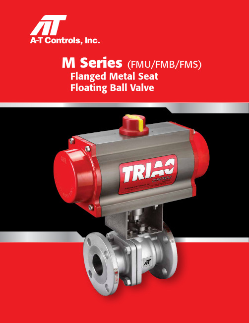
1M Series (FMU/FMB/FMS)Flanged Metal Seat Floating Ball ValveFlanged Metal Seat Floating Ball ValveFull Bore Two-piece Flanged Ends ASME Class 150/300/600Product FeaturesHVOF Thermal SpraySeat Area A Seat Area B temperature and abrasive fluids. It is used in industries such as Oil Petrochemicals, Power Generation, ISO 10497 - 3rd EditionF I R E S A F E C E R T I F I E DPreferred directionFlow direction3Black liquor is viscous, and will cake in small cavities and on surfaces, which prevents valves from operating properly. A-T Controls provides a solution to this harsh service with modifications to our FMS Series. Black liquor valves include an Aflas ® O-ring on both seats to avoid black liquor media build-up, and a venturi hole in the ball to evacuate the cavity as media flows.Upstream Seat Downstream SeatScraper SeatsScraper Seat with HighVelocity Oxygen Fuel (HVOF) applied Tungsten Carbide Coated Trim is designed to BallSeatSeat SpringStainless Steel HCr Coated SST TC Coated SST CrC Coated SSTStellite ® Inlay SST TC Coated SST CrC Coated SST Inconel ® 718 SSTInconel ® X750Aflas ® O-rings (4)seal seat cavity, blocking from any media build-up.(400°F max temp.)Venturi Hole in Ballhelps evacuate cavity as flow passes by.Black Liquor Service(May also be applicable for other services)Scraper Standard Scraper Service (FMS)For heavy slurry such as in the pulp & paper industry.Flow directionFlow directionFlanged Metal Seat Floating Ball Valve Floating Metal Seat Ball ValveApplicable Standards• Standard Body Material: WCB or CF8M (other Alloys available)• Nominal Size & Pressure Rating: 1/2” to 8” ASME Class 150/300; 1/2”-4” ASME Class 600• End Connections: Raised Face Flange • Temperature Range: -50°F to 1000°F • Fire Safe: Certified to ISO 10497 3rd Edition • Face to Face Dimensions: ASME B16.10• Flange Dimensions: ASME B16.5• Body Pressure Testing: ASME B16.34, API 598• Seat Leakage Testing: ANSI B16.104, FCI 70-2 Class V or Class VI • Casting: MSS-SP-25/MSS-SP-55•Safety Integrity: SIL 3 CapableTechnical Specifications82763591111312104MATERIALS LISTVALVE OPTIONS CARBON STEELSTAINLESS STEEL STELLITE® SEAT TUNGSTEN CARBIDE CHROME CARBIDE STELLITE® SEAT TUNGSTEN CARBIDE CHROME CARBIDE NO.PART NAME -20°F - 750°F-20°F - 800°F-20°F - 800°F-50°F - 750°F-50°F - 900°F-50°F - 1000°F1BODY ASTM A216 GRADE WCB ASTM A351 GRADE CF8M 2CAP ASTM A216 GRADE WCB ASTM A351 GRADE CF8M3BALL ASTM A351 GRADE CF8M + HCr ASTM A351 GRADE CF8M + TC ASTM A351 GRADE CF8M + CrC ASTM A351 GRADE CF8M + HCr ASTM A351 GRADE CF8M + TC ASTM A351 GRADE CF8M + CrC4SEAT AISI 316 + STELLITE®AISI 316 + TC AISI 316 + CrC AISI 316 + STELLITE ®AISI 316 + TC AISI 316 + CrC 5SEAT GASKET GRAPHITE GRAPHITE6SEAT SPRING INCONEL ®X750INCONEL ® X7507BODY GASKETAISI 316 + GRAPHITE AISI 316 + GRAPHITE 8BOLT ASTM A193 GRADE B7ASTM A193 GRADE B8NUTASTM A194 GRADE 2H ASTM A194 GRADE 89THRUST WASHER AISI 31610GLAND PACKINGAISI 316 + GRAPHITE11STEM*17-4 PH ®/ XM-19/ DUPLEX 2205/INCONEL ®718XM-19/DUPLEX 2205/INCONEL ® 718XM-19/DUPLEX 2205/INCONEL ® 71812GLAND AISI 30413GLAND BOLTAISI 304TRIM ABBREVIATIONS:HCr = Hard Chrome Plated; TC = Tungsten Carbide; CrC = Chrome Carbide*Various usage conditions shall determine stem material 17-4 PH ® SST: use below 750°F XM-19: use up to 1100°FDUPLEX 2205: use below 570°F INCONEL ® 718: use up to 1100°F5Dimensions (in.) ASME Class 150Dimensions (in.) ASME Class 300Dimensions (in.) ASME Class 600SIZE A B C D E F I J L N Q W Y Z AB DD NN ISO 5211LBS ½"0.590.39 5.12 1.480.55 2.48 1.38 2.38 4.25 3.740.630.440.98M5 1.69 1.6544F044¾"0.790.39 5.12 1.590.55 2.68 1.69 2.76 4.61 3.860.630.440.98M5 1.81 1.6544F0451"0.980.47 6.30 1.870.55 2.99 2.01 3.13 5.00 4.250.630.44 1.20M6 2.09 1.9694F0571½" 1.500.678.82 2.560.75 3.46 2.87 3.88 6.50 5.000.630.56 1.65M8 2.83 2.7564F07142" 1.970.678.82 2.830.75 3.70 3.62 4.747.01 5.980.750.63 1.65M8 3.11 2.7564F07202½" 2.560.7912.76 3.580.75 4.53 4.13 5.497.487.010.750.69 1.83M8 3.35 2.7564F07293" 2.990.7912.76 3.920.75 4.72 5.00 6.007.997.480.750.75 1.83M8 3.82 2.7564F07394" 3.94 1.0615.75 4.80 1.027.68 6.187.509.028.270.750.94 2.11M10 4.45 4.0168F10626" 5.91 1.2621.65 6.61 1.189.458.509.5115.5110.980.87 1.00 2.44M12 5.91 4.9218F121408"7.871.38N/A8.681.38N/A10.6311.7517.9913.500.871.132.80M168.315.5128F14285SIZE A B C D E F I J L N Q W Y Z AB DD NN ISO 5211LBS ½"0.590.39 5.12 1.480.55 2.48 1.38 2.62 5.51 3.740.630.560.98M5 2.32 1.6544F046¾"0.790.39 5.12 1.590.55 2.68 1.69 3.25 5.98 4.610.750.630.98M5 2.64 1.6544F0481"0.980.47 6.30 1.870.55 2.99 2.01 3.50 6.50 4.880.750.69 1.20M6 2.83 1.9694F05111½" 1.500.678.82 2.560.75 3.46 2.87 4.517.48 6.140.870.81 1.65M8 3.23 2.7564F07222" 1.970.678.82 2.830.75 3.70 3.62 5.008.50 6.500.750.88 1.65M8 3.78 2.7568F07272½" 2.560.7912.76 3.580.75 4.53 4.13 5.879.497.480.87 1.00 1.83M8 3.90 2.7568F07503" 2.990.7912.76 3.920.75 4.72 5.00 6.6111.148.270.87 1.13 1.83M8 5.08 2.7568F07704" 3.94 1.0615.75 4.80 1.027.68 6.187.8712.0110.000.87 1.25 2.11M10 5.43 4.0168F101056" 5.91 1.2621.65 6.61 1.189.458.5010.6315.8712.520.87 1.44 2.44M12 6.69 4.92112F122208"7.871.38N/A8.681.38N/A10.6313.0019.7615.000.981.632.80M168.905.51212F14380SIZE A B C D E F I J L N Q W Y Z AB DD NN ISO 5211LBS ½"0.590.39 5.12 1.480.55 2.48 1.38 2.62 6.50 3.740.630.820.98M5 2.28 1.6544F046¾"0.790.39 5.12 1.590.55 2.68 1.69 3.257.48 4.610.750.880.98M5 2.76 1.6544F0491"0.980.47 6.30 1.870.55 2.99 2.01 3.508.50 4.880.750.94 1.20M6 3.86 1.9694F05131½" 1.500.678.82 2.560.75 4.72 2.87 4.519.49 6.140.87 1.13 1.65M8 4.25 2.7564F07262" 1.970.678.82 3.230.75 5.51 3.62 5.0011.50 6.500.75 1.25 1.65M8 5.28 2.7568F07403" 2.990.8712.76 4.51 1.107.09 5.00 6.6114.028.270.87 1.50 1.83M10 6.50 4.0168F10804"3.941.0621.655.281.309.456.188.5017.0110.750.981.752.09M128.154.9218F12150ABLQ-NNWEC/LA-T Controls reserves the right to change product designs and technical/dimensional specifications without notice.M SeriesFloating Metal Seat Ball Valve6FMU/FMB Series Metal Seat Torque Table1) Safety factors should be added for high temperature, viscous fluid, powders, steam and slurries.2) Torques are based on valve being installed in suggested direction. Consult The Application Sizing Guide for assistance withsizing actuators.02004006008001000120014001600TC CrCHCr Stellite ®WCB (-28)-20(-18)(38)100(93)200400(204)(149)300(260)500(316)600(371)700900(482)(427)800(538)1000HCr/Stellite ® Trim = Max Temperature 750°F (399°C)WCB Body = Max Temperature 800°F (425°C)TC Trim = Max Temperature 900°F (482°C)CrC Trim = Max Temperature 1000°F (538°C)T °F (°C)WCB BodyCF8M BodyTC CrCWCB 900(482)7)0(538)1000HCr/Stellite ®Trim = Max Temperature 750°F (399°C)WCB Body = Max Temperature 800°F (425°C)TC Trim = Max Temperature 900°F (482°C)CrC Trim = Max Temperature 1000°F (538°C)Pressure vs. Temperature BODY MATERIAL2004006008001000120014001600ASME Class 600 BodyASME Class 300 BodyASME Class 150 Body(-28)-20(-18)(38)0100(93)200400(204)(149)300(260)500(316)600(371)700(425)800(432)900(538)1000ASME B16.34 A216-WCB P/T CurveP (P S I G )CF8M Body WCB BodyTemperature & Pressure CurvesTemperature °F (°C)P r e s s u r e (P S I G)D i f f e r e n t i a l P r e s s u r e (P S I G )Pressure vs. TemperatureTRIM OPTIONS • P/T @ Max. Shutoff ∆P316 HCr/Stellite ® Trim, Unidirectional and Bidirectional (316/TC Trim or CRC Trim add 20% to belowtorques)Torques (in*lbs) @ PSIGPSIG 1502002853504005006006507408701000116013001480½"90929598100104108110114119124130136142¾"1301321371401421471521551591651721801871941"1501651902092542542832983253634024494915351½"415463543605653748843890976CF CF CF CF CF 2"4905636887848571,0041,1501,2241,356CF CF CF CF CF 2½”7127919241,0261,1051,262CF CF CF CF CF CF CF CF 3"1,2321,4351,7812,0452,2492,655CF CF CF CF CF CF CF CF 4"2,6003,1804,1674,9215,5016,662CF CF CF CFCFCFCFCF6"5,3836,3348,2519,971CF CF CF CF CF 8"10,18111,86515,21718,194CFCFCFCFCFSize Cv 1/2”253/4”501”901-1/2”2452”4602-1/2”7503”1,1254”2,1006”5,0508”9,600Cv ValuesNote: Safety factors can be interpolated for intermediate temperatures. Temperature °F Recommended Safety Factor MultiplierLess Than 2001400 1.1550 1.3750 1.6850CF 950CF 1000CFTorques can be interpolated for intermediate pressures.1 Fire Safe DesignationF Fire Safe Tested2 Valve SeriesMU Metal Seat Unidirectional Shut-off, Floating Ball MB Metal Seat Bidirectional Shut-off, Floating Ball MS Metal Seat Scraper Seat Design3 Body MaterialBlank No Designation = Stainless Steel Body and Trim CF8M-316 SSTC Carbon Steel Body, A216 Gr WCBL Low Carbon 316 SST, CF3M-316LD CD3MN Duplex SSTG CE3MN Super Duplex SST4 F316H Forged5 LCB, A3528 LCC, A3526 WC6, A2179 WC9, A2174 End ConnectionF1 150# Flanged EndsF3 300# Flanged EndsF6 600# Flanged EndsFR 600# RTJ Flanged Ends5 Valve Size0050 1/2”0075 3/4”0100 1”0150 1-1/2”0200 2”0250 2-1/2”0300 3”0400 4”0600 6”0800 8”6 Seat, Lining & Trim MaterialsB Black Liquor Service (TC 316SST Seats & Ball)2 Tungsten Carbide Coated 316SST Seats & Ball3 HCr Coated Ball /w Stellite® Inlay Seats4 Chrome Carbide Coated 316SST Seats & Ball8 Chrome Carbide Coated Inconel® 718 Seats & Ball 7 Special DesignationsX No SpecialsG Gear Operator8 Additional SpecialsX No SpecialsO Oxygen CleanedZ Special End ConfigurationV Vented Ball9 Special Stem DesignationBlank No Designation = Standard StemA 17-4PH® StemB XM-19 (Nitronic® 50) StemC Duplex 2205 StemD Inconel® 718 StemManual Ball Valve Part Number MatrixHow To Order1-2-3-4-5-678-9------Stellite® is a registered trademark of the Deloro Stellite Company, Inc. Inconel® is a registered trademark of Inco Alloys/Special Metals Corporation.789955 International Blvd.Cincinnati, Ohio 45246PH 513-247-5465FAX 513-247-5462********************FMU-20210811Copyright 2013 A-T Controls, Inc.LIT0017ISO 9001:2015 Certified。
A-T Controls NS Series 浮动球阀和浮动闸阀说明书
NS S erieSBall & Butterfly ValvesNSF/ANSI 61 & 372 Certifiedt V al v e s f o rW ae rApplications• Water Treatment• Potable Water Service • Reverse Osmosis • DesalinationA-T Controls’ NS Series floating ball valves and NS series butterfly valves are certified to meet the requirements of NSF 61 (Drinking Water System Components- Health Affects) and NSF 372 (Drinking Water System Components- Lead Content). This means that NS Series valves are certified for use (by Underwriters Laboratory) in water treatment, water purification, potable water, and water distribution systems and conforms with North American lead content requirements for “lead-free” plumbing.The NS Series valves include a tag showing that the valve assembly is certified to NSF 61 and NSF 372.NS butterfly valves are available in sizes 2” – 24”, and have Class 150 flanges. NS Series ball valves are available with threaded, socket weld, butt weld, Class 150, and Class 300 end connections.NSF 61 & 372CERTIFIED VALVESVALVE NSF/ANSI 61 ALSO CERTIFIED TONSF/ANSI 372<5DZ0>Top MountingLocation for 2-1/2" – 3"Top ViewW 4NO. PART NAME QTY MATERIAL1BODY 1ASTM A351 GRADE CF8M 2END CAP1ASTM A351 GRADE CF8M3BALL 11/4" THRU 3/8" ASTM A276 SS3163BALL 11/2" THRU 3" MATERIALS LIST• Two piece design• Available in stainless steel • Full port 1000 psi • Threaded ends onlySAMPLE PART #Valve SeriesEnd ConnectionSeat MaterialValve Size Special DesignationAdditional Special DesignationNS20-TH-0200-XXXNOTE: Dotted line shows the rating for valve body. Solid line shows the rating for valve seat. Both ratings need to be considered when determining the limitation of the valve for specific application.TEMPERATURE IN °F (°C)P R E S S U R E I N P S I GPRESSURE IN BAR1000(-18)-20(-28)0100(38)30020040080050060070090011001000500(260)(149)200300(93)400(204)6.9013.720.727.655.234.541.448.362.175.970.0600(316)1/4"~3"R TF E P T F EPressure vs. TemperatureVALVE NSF/ANSI 61AND ALSO CERTIFIED TONSF/ANSI 372<5DZ0>2-PC FULL PORT | THREADEDSeries NS20* 1/4” - 1/2” - 1 PC 3/4” - 2” - 2 PCS 2-1/2” - 3”- 3 PCSDIMENSIONS (IN)material, consult factorySTANDARDSDesignANSI/ASME B16.34End ConnectionsASME B1.20.1Sulfide Stress Protection NACE MR0175MountingISO 5211Marking System for Valves MSS SP-25, MSS SP-55Safety IntegrityIEC 61508:2010; SIL 3Material Certification EN 10204-3.1 MTR SAMPLE PART #Valve SeriesEnd ConnectionSeat MaterialValve Size Special DesignationAdditional Special DesignationNS22-TH-0200-XXXNOTE: Dotted line shows the rating for valve body. Solid line shows the rating for valve seat. Both ratings need to be considered when determining the limitation of the valve for specific application. Consult factory for other seat materials.TEMPERATURE IN °F (°C)P R E S S U R E I N P S I GPRESSURE IN BAR1000(-18)-20(-28)0100(38)300200400800500600700900500(260)(149)200300(93)400(204)6.9013.720.727.655.234.541.448.362.175.970.0600(316)Pressure vs. Temperature6NSF/ANSI 61 & 372 Certified Valves | A-T Controls, Inc. | ^1/2” - 1” - 2 PCS1-1/2” - 2-1/2” - 3 PCS *1/2” - 2” - 4 PCS 2-1/2” - 8 PCSDIMENSIONS (IN)7NSF/ANSI 61 & 372 Certified Valves | A-T Controls, Inc. | 8NSF/ANSI 61 & 372 Certified Valves | A-T Controls, Inc. | 9NSF/ANSI 61 & 372 Certified Valves | A-T Controls, Inc. | 30° V-Port60° V-Port 90° V-PortNote: May be customized; call factory for flow analysis design.* Refer to pg 3 of the V-Series Control Port Ball Valve Catalogfor Cv values.NSV9 Series:The NS90 & NSD9 Series’ are available with a v-port ball option (30°, 60°, or 90° V-notch). V-port valves o ffer better and more consistent control t han traditional round ported ball valves. W e offer this valve with the control port c ast and machined into the ball, not in t he seat. This allows for much better flow characteristics and eliminates the need to replace seats. The 30° option allows for finer tapered control throughout the valve rotation, and the 60° & 90° offer a larger Cv in addition to controlled flow.The RTFE seat is standard in the both the NSV9 and NSD9 Class 150 and Class 300.Series NSV9• 2 pc. Flanged Ball Valve • V-Port• ANSI Class 150 or 300• 1/2”- 6”NSV9-F1-0600-XXX-6SAMPLE PART #Valve SeriesEnd ConnectionValve SizeSeat MaterialSpecial Designation Additional Special Designation Port Designation10NSF/ANSI 61 & 372 Certified Valves | A-T Controls, Inc. | Series NSD9-F32-1/2” - 8 PCS & 1/2” - 1” - QTY 21-1/2” - 2-1/2” - QTY 311NSF/ANSI 61 & 372 Certified Valves | A-T Controls, Inc. | 6” - QTY 1012NSF/ANSI 61 & 372 Certified Valves | A-T Controls, Inc. | * Refer to the Resilient Seated Butterfly Valve Catalog for NS Series Automated Package Sizing and other material options, when NSF61 is not required.VALVE NSF/ANSI 61 ALSO CERTIFIED TONSF/ANSI 372<5DZ0>Pressure TestingAPI 598Mounting ISO 5211Markings API 609, ASME B16.34, MSS SP-25Material CertificationEN 10204-3.1 MTR Quality Assurance ISO 9001:2015CERTIFICATIONSDrinking Water System Components NSF/ANSI 61 & 372Health Effects & Lead ContentCanada Registration CRN 0C20682.5ABS Approval (Pending)Page ReferencePage 12 ........Product Details and Standards Page 13 ........Bill of Materials 2”-14”Page 14 ........Bill of Materials 16”-24”Page 15 ........DimensionsPage 16 ........Cv Values and Operating Torques andPressure & Temperature RatingsPage 17 ........Handles and Gear Operator Sizing Page 18 ........Automation CapabilitiesPage 19 ........How To Order: NS Series Part Number Matrix»»»Lug or Wafer body, ANSI 125/150 flangesBill of Materials | 2” - 14”**one bushing(7) is not shown; it is located below lower stem flangebushing(6)13Bill of Materials | 16” - 24”*16”-20” valves have quantity 214NSF/ANSI 61 & 372 Certified Valves | A-T Controls, Inc. | Dimensions | 2” - 24”ANSI/ASME Class 150• Unless otherwise specified, all dimensions are in inches.• Face-To-Face dimensions (E) are across the body flats (metal-to-metal). Approximately 1/16” of the rubber seat protrudes from each side for flange sealing.• 2” - 24” Lug valve end connections conform to ANSI B16.5 Class 150, Wafer valve end connections conform to ANSI B16.5 Class 150 and EN1092-2 PN 10/16.A-T Controls reserves the right to change product designs and technical/dimensional specifications without notice. See website for updates.15NSF/ANSI 61 & 372 Certified Valves | A-T Controls, Inc. | 16,52826,15739,23643,116 Approximate Operating Torque(In•lbs)Seat Temperature RatingsTEMPERATURE IN °F (°C)PRESSUREINPSIG PRESSURE IN BAR(-28)-2050100150200250(-18)(38)0100(93)200300350400400(204)(149)300(260)5003.56.9101417212428Pressure vs. Temperature Chartfor NS Butterfly Valves 2”-24”Pressure vs. Temperature16NSF/ANSI 61 & 372 Certified Valves | A-T Controls, Inc. | 17NSF/ANSI 61 & 372 Certified Valves | A-T Controls, Inc. | Handle and Gear Operator Sizing18NSF/ANSI 61 & 372 Certified Valves | A-T Controls, Inc. | Automated ValveAssembliesPneumatic or Electric Pre-engineered assemblies Pre-sized and pre-priced Double Acting or Spring Return OptionsButterfly Valve packages®APLAluminum or Stainless Steel housing Weatherproof/explosion proof construction Dome indicatorEasy-Set cams Captive boltsMany switch options AS-I systemsCan be mounted onmanual valvesLimit SwitchesAPL-310NAPL-210NCSA Approved, Type 4XSee individual brochures for details & optionsAPL-910NStainless Steel Type 4X, IP 67S2 Series Stainless Steel Actuators19Part Number Matrix for A-T Controls NSF/ANSI 61 & 372 Certified ValvesEXAMPLE:NS-L1-0400-NSR-XANSF 61 & 372 Approved 4” NS Series RSBFV, Class 125/150 Lug Style, A351 CF8M Body, EPDM Dead-End Service Seat, A351 CF8M Disc, PTFE Stem Bushing, 17-4 PH Square Stem, Bare Stem.A-T Controls NS Series BUTTERFLY ValvesA-T Controls NS SeriesBALL ValvesEXAMPLES:NS55-TH-0200-XXXSeries 55 Full Port Ball Valve with 2” NPT threaded ends, 316SST Body and Trim, 1000 psi WOG, F05 B.C., RTFE Seats/Stem Seal, PTFE Joint Gaskets/Packing. Assembled grease free. Certified for NSF/ANSI 61-2016 and NSF/ANSI 372-2011 for up to 60°C service (UL Certification Mark tag included).NSD9-F3-0100-XXX1” Series D9 Class 300 Full Port Ball Valve. 316SST Body and Trim, F04/F05 B.C., RTFE Seats/Stem Seal, PTFE Joint Gasket/Packing. Assembled grease free with no stem o-ring. Certified for NSF/ANSI REPAIR KIT EXAMPLES: NS55-RK-0200-PTFESeries NS55 2” Repair Kit containing: (2) PTFE Seats, (1) set of PTFE packing, (1) RTFE Stem Seal, (2) PTFE Joint GasketsNS55-RK-0200-RTFESeries NS55 2” Repair Kit containing: (2) RTFE seats, (1) set of PTFE packing, (1) RTFE Stem Seal, (2) PTFE Joint Gaskets。
浮动式球阀使用说明
Q41F球阀使用说明书高能阀门集团有限公司Q41F1、概述浮动式球阀是新一代高性能球阀,适用于长输管线和一般工业管线,其安全、耐恶劣环境性等在设计时均已进行了特殊考虑,适用于各种腐蚀性和非腐蚀性介质。
它可安装在石油、化工、食品、医药、冶金、矿山、水电、天然气、煤气、城建等系统;可以任意安装。
2、特点1、本阀为二块式阀体结构,每阀有两个阀座,每个方向都能密封,因而没有流向限制,是双向阀;中法兰用螺柱连接,上阀杆设有滑动轴承,减少磨擦,使操作省力、平稳。
2、管道中流体压力在球体上产生的作用力由二阀座支撑便得到平衡、球体不会移动,阀门密封靠阀座的弹性介质压力实现;阀座变形小、操作力矩轻、密封性能可靠,使用寿命长。
3、在工作中,阀门处于全开或全关时,卸掉中腔压力可直接更换阀杆填料。
4、在0°∽150°范围内启闭。
5、密封性能好,密封试验渗漏量为零;改变材质时可适用于多种介质。
3、主要性能规范4、主要零件材料5、结构简图Q41F铸钢法兰球阀--主要外型尺寸6、安装、使用与保养注意事项1、产品在出厂前都已经按(JB/T 9092)有关标准的规定进行检验合格,执行装置调试完毕。
为了保证产品的使用效果,请勿随意调整紧固件、定位装置等。
2、阀门安装前应做以下工作①要使阀体上的流向指示与管道介质流向一致;②查验管道法兰是否与阀门连接尺寸一致,安装时要均匀拧紧螺母,法兰垫片对称放置;③认真校对使用工况与本产品的工作压力、工作温度、耐腐蚀性是否相符;④检查阀门通道和启闭件是否附着污物,如果有污物应进行清理,清理时不得损伤密封面;⑤检查阀门各部件是否连接紧固;⑥该阀门双向密封,做0∽90°旋转启闭。
观察阀门的启闭位置是否与此相符,并检查有无卡阻现象。
3、该阀可以任意安装,可作切断阀用;4、手动操作时顺时针为关,逆时针为开,操作时注意观察位置指针或指示盘刻度;5、阀门在使用中遇到故障时应及时查明原因,及时排除,不得敲砸,强行启闭。
球阀使用说明书
2、阀门两端连接采用法兰结构或长焊接端,浮动球阀阀体和阀盖
连接处密封采用 PTFE 垫片。
3、阀杆采用有防飞出功能的下装结构。
4、扁式阀杆头的设计能让装配的手柄始终与流体通道平行。装配
中,应避免手柄未达到预定位置。
五、阀门运输和保管
1、阀门运输 (1)在运输过程中,应将阀门用纸箱或木箱包装。如纸箱或木箱 无法包装阀门时,应用托盘将阀门固定好,做防尘防水处理。 (2)在装载阀门时,不要让传动装置承受任何外力。 (3)避免装载设备时超载,货物摆放要宽松,避免阀门受撞击。 (4)所有的阀门搬运都应该很小心,对于大口径的阀门应该用起 吊设备。 2、阀门保管
片,可以作为修理和维护的备用零件进行订购。 8、分解及再装配时必须小心防止损伤零件的密封面,特别是非金 属零件,取出 O 型圈时宜使用专用工具。 9、分解下来的单个零件可以用浸洗方式清洗。尚留有未分解下来 的非金属件的金属件可采用干净的细洁的浸渍有清洗剂的绸布 (为避免纤维脱落粘附在零件上)擦洗。清洗时须去除一切粘附 在壁面上的油脂、污垢、积胶、灰尘等。 10、非金属零件清洗后应立即从清洗剂中取出,不得长时间浸泡。 11、清洗后需待被洗壁面清洗剂挥发后(可用未浸清洗剂的绸布 擦)进行装配,但不得长时间搁置,否则会生锈、被灰尘污染。 12、使用润滑脂润滑。润滑脂应与阀金属材料、橡胶件、塑料件 及工作介质均相容。在密封件安装槽的表面上涂一薄层润滑脂, 在橡胶密封件上涂一薄层润滑脂,阀杆的密封面及摩擦面上涂一 薄层润滑脂。
高压水密封实验压力
1.76MPa
低压气密封实验压力
0.6MPa
适用温度℃
-29~200
三、工作原理
球阀的主要功能是切断或接通管道中的流体。当手动或其它
手动球阀使用说明
球阀使用说明书 Q41F 浮动式球阀球 阀 (Ball Valve)球阀是由旋塞演变而来的,它的启闭件为一个球体,利用球体绕阀杆的轴线旋转90度实现开启和关闭的目的。
球阀在管道上主要用于切断、分配和改变介质流动方向,设计成V 形开口的球阀还具有良好的流量调节功能。
球阀不仅结构简单,密封性好,而且在一定的公称通径范围内体积较、重量轻、材料耗阀门品种之一。
特别是在美、日、德、法、意、西、英等工业发达国家,球阀的使用非常广泛,使用品种和数量仍在继续扩大,并向高温、高压、大口径、高密封性、长寿命、优良的调节性能以及一阀多功能方向发展,其可靠性及其他性能指标均达到较高水平,并已部分取代闸阀、截止阀、节流阀。
随着球阀的技术进步,在可以预见的短时间内,特别是在石油天然气管线上、炼油裂解装置上以及核工业上将有更广泛的应用。
此外,在其他工业中的大中型口径、中低压力领域,球阀也将会成为主导的阀门类型之一。
球阀结构爆炸图序号名称数量1 阀盖 12 密封垫 13 四氟密封圈 24 螺帽 45 螺栓 46 球 17 阀体 18 内六角螺丝 29 四氟填料 410 压盖 111 阀杆 112 四氟圈(阀杆密封) 1另有定位片、手柄、蜗轮、电动头(视工况而定)球阀的优点是:(1) 具有最低的流阻(实际上为零)。
(2) 因在工作时不会卡住(在无润滑剂时),故能可靠地应用于腐蚀性介质和低沸点液体中。
(3) 在较大的压力和温度范围内,能实现完全密封。
(4) 可实现快速启闭,某些结构的启闭时间仅为0.05~0.1s,以保证能用于试验台的自动化系统中。
快速启闭阀门时,操作无冲击。
(5) 球形关闭件能在边界位置上自动定位。
(6) 工作介质在双面上密封可靠。
(7) 在全开和全闭时,球体和阀座的密封面与介质隔离,因此高速通过阀门的介质不会引起密封面的侵蚀。
(8) 结构紧凑、重量轻,可以认为它是用于低温介质系统的最合理的阀门结构。
(9) 阀体对称,尤其是焊接阀体结构,能很好地承受来自管道的应力。
5-球阀说明书
浮动球阀使用说明书1 范围本说明书包括了公称通径DN15mm~150mm(1/2”~20”)、公称压力PN1.6MPa~10MPa(ANSI CLASS150~600)螺纹端、法兰端、对焊端和承插焊端连接的手动、齿轮传动、电动和气动操作的二分体式(对分式)和三分体式(对夹式)的浮动球球阀和固定球球阀。
2 用途2.1主要供开启或关闭管道和设备的介质用。
2.2根据介质选用阀门的材质。
2.2.1碳钢阀门适用于水、蒸汽、油品等介质。
2.2.2不锈钢阀门适用于腐蚀性介质。
2.3适用温度取决于阀座的材质。
PTFE(聚四氟乙烯)≤130℃PTFE(聚四氟乙烯)+玻纤≤160℃PPL(对位聚苯)≤300℃3 结构3.1球阀基本结构见图13.2易损件垫片,填料采用聚四氟乙烯或柔性石墨,密封可靠。
4 操作4.1手动操作阀门采用手柄或齿轮传动装置、电动或气动球阀由电动装置或气动装置驱动,使球体旋转90°开启或关闭阀门。
4.2手动球阀阀杆顶端刻有凹槽。
凹槽方向及扳手长度方向与流道方向一致为开启,与流通方向垂直为关闭。
4.3电动、气动球阀的开启、关闭指示由电动装置、气动装置上的位置指示器标识。
5 保管、保养、安装和使用5.1阀门应存放在干燥,通风的室内,阀门通道两端应堵塞。
5.2长期存放的阀门应定期检查,清除污物。
应特别注意密封面的清洁,防密封面的损坏。
5.3安装前应仔细核对阀门标志是否与使用要求相符。
5.4安装前应检查阀门通道和密封面,如有污垢,应使用清洁布擦拭干净。
5.5安装前检查填料是否压紧,应确保填料的密封性,同时不应妨碍阀杆的转动。
5.6安装后系统或管路试压时,阀门必须处于全开位置。
5.7使用中应将球体全开或关闭,不应将球体部分开启做调节流量用。
5.8手动阀门在开启或关闭操作时,应使用手柄开、关,不得借用辅助杠杆或其它工具。
5.9阀门使用应定期检查,检查密封面有无磨损及垫片填料。
若损坏失效,应及时修理或更换。
NUTRON Model T3 钢铁浮球阀说明书
NUTRON Model T3ContentNUTRON* Model T3 Ball ValvesSizes, specifications, and compliance� � � � � � � � � � � � � � � � � � � � � � � � � � � � � � � � � � � � � � � � � � � � � � � �3Standard features � � � � � � � � � � � � � � � � � � � � � � � � � � � � � � � � � � � � � � � � � � � � � � � � � � � � � � � � � � � � � � � � � � � � � � � � �4Available sizes and how to order � � � � � � � � � � � � � � � � � � � � � � � � � � � � � � � � � � � � � � � � � � � � � � � � � � � � � �5Valve details and materials lists � � � � � � � � � � � � � � � � � � � � � � � � � � � � � � � � � � � � � � � � � � � � � � � � � � � � � � �6Valve assemblies and dimensions tables� � � � � � � � � � � � � � � � � � � � � � � � � � � � � � � � � � � � � � � � � � 12Actuator mounting dimensions � � � � � � � � � � � � � � � � � � � � � � � � � � � � � � � � � � � � � � � � � � � � � � � � � � � � � � 28Pressure and temperature ratings (seats and seals)and breakaway torque data � � � � � � � � � � � � � � � � � � � � � � � � � � � � � � � � � � � � � � � � � � � � � � � � � � � � � � � 30Services for valves and actuation � � � � � � � � � � � � � � � � � � � � � � � � � � � � � � � � � � � � � � � � � � � � � � � � � � � 31 2Sizes, Specifications, and ComplianceModel T3 three-piece threaded floating ball valves■Full-port sizes: 1/2–3 in [13–76 mm]■Reduced-port sizes: 3/4–4 in [19–102 mm]■ASME Classes 150–2500 [PN 20–420] (see page 5)■Water, oil, gas (WOG) pressure 1,000–6,000 psi (see page 5)■End connections: threaded, flanged, socket weld, and butt weld Materials and actuation■Materials: carbon steel, stainless steel, and special alloys■Operator: manual lever handle■Actuation: consult Cameron for information on various types of actuators, including gear operators, pneumatic, hydropneumatic, electric, electropneumatic, and hydraulic actuators Compliance to standards and specifications■ISO 9001:2000 registered quality system■ASME B16�34■API 607 4th Edition (fire safe)■CE Mark Number 0038■ASME Section VIII, Division 1 boiler and pressure vessel code ■CSA Z245�15 steel valves■NACE MR0175 (Rev� 2002)■Canadian Registration Number (CRN)■API 603 (conduit factory) Model B3ENUTRON Model T3 ball valve.Standard FeaturesBody constructionForged-steel, three-piece threadedconstruction� A machined pad area is drilled and tapped for actuation as a standard� Threaded construction enables combinationsof end connections�CapscrewDual purpose, which allows for easy stem packing adjustment without handle removal while providing a stop for the handle�HandleRugged cast handle that indicates flow position� When the handle is positioned in line with the pipe, the valve is open� When the handle is positioned perpendicular to the pipe, the valve is closed� Locking handle is standard for all 2-in [51-mm] reduced-port and smaller valves with either socket weld or FNPT end connections�PackingSelf adjusting by means of a Belleville washer� Allows for long service life before manual packingadjustment is necessary�Thrust washerDesign that acts as a bearing between the body and stem�Ball Floating ball design allows positive shutoff in either flow direction� Includes pressure equalization hole to prevent trapping of pressure inthe body cavity�StemBlowout-proof stem that is backseated through the valve body�Body sealsO-rings placed ahead of the body cap threads to protect the threads from the flow media�Seats Available in Teflon®, Delrin®, polyetheretherketone (PEEK), and Devlon® materials�Stem sealO-ring installed on stem shaft on all valves 11/2-in [38-mm] full port through 3-in [76-mm] reduced port�4Available SizesSizes, in [mm]ASME Class [PN]150 [20]300 [50]600 [100]900 [150]1500 [250]2500 [420] Full port minus 1 in [25 mm]1/2–3 [13–76]1/2–3 [13–76]1/2–2 [13–51]1/2–2 [13–51]1/2–2 [13–51]1/2–2 [13–51] Reduced port minus 11/2 in [38 mm]3/4–4 [19–102]3/4–4 [19–102]3/4–3 [19–76]3/4–3 [19–76]3/4–3 [19–76]3/4–3 [19–76] Sizes, in [mm]WOG Pressure, psi–1,0002,0003,0004,0006,000Full port, threaded– 3 [76]1/4–3 [6–76]1/4–2 [6–51]1/4–2 [6–51]1/4–2 [6–51] Reduced port, threaded– 4 [102]3/4–3 [19–76]3/4–3 [19–76]3/4–3 [19–76]3/4–3 [19–76] Full port, socket weld––1/2–2 [13–51]1/2–2 [13–51]1/2–2 [13–51]1/2–2 [13–51] Reduced port, socket weld––3/4–3 [19–76]3/4–3 [19–76]3/4–3 [19–76]3/4–3 [19–76]T3 - F 07 S 20 SZExampleSize, in [mm]021/4 [6]033/8 [10]1211/4 [32]1511/2 [40]20 2 [51]2521/2 [64]30 3 [76]40 4 [102]End ConnectionA Raised face (RF)smooth faceB Butt weld (BW)Sch. 40C BW Sch. 80D BW Sch. 160E BW Sch. XXHF Female NPT (FNPT)× Male NPT (MNPT)G FNPT × RFH FNPT × ring-typejoint (RTJ)J RTJM MNPTWS Socket weldStyle†Temp. Rating,degF [degC]A Stainless steel−50 [−46]B StandardH High-temperature sour500 [260]L Low-temperature sour−50 [−46]N MONEL® alloy steel–50 [–46]Pressure101,000-psiWOG404,000-psiWOG606,000-psiWOG01150 ASME03300 ASME06600 ASME09900 ASME151500 ASME252500 ASME†C onsult Cameron for detailed valve style descriptions, full range of options, materials,actuation packages, or for a particular special valve service application.T3-F07S20SZ: Model T3, full port, 3/4 in [19 mm],FNPT, 2,000-psi WOG, sour valve, fire safeHow to OrderModelBoreSize PressureStyle†Fire safeCommon Options†Antistatic springCar seal closeCar seal openDelrin material seatsElectroless nickel plating (ENP)Gear operatorGraphite packingHighly satured nitrile (HSN) O-ringsZPEX® coatingLocking handleNitrile O-ringsPEEK seatsTeflon material O-ringsViton material O-rings5Valve Details and Materials ListsThreaded End Connections131210911153a 143813265415626Valve Details and Materials Lists Materials ListsItem Part Working Pressure, psi Low-Temperature Sour Stainless Steel −50 degF [−46 degC]■ Major repair kit.● Minor repair kit.† Only available on sizes 11/2-in [38-mm] full-port through 3-in [76-mm] reduced-port valves.‡ Locking device is standard on 1/4-in [6-mm] full-port through 2-in [51-mm] reduced-port valves.Fire-safe trim offered as standard whenever possible. Consult Cameron for fire-safe trim.7Socket Weld and Threaded × Socket Weld End Connections131210911152b1438132a6541562a3a Valve Details and Materials Lists8Valve Details and Materials Lists Materials ListsItem Part Working Pressure, psi Low-Temperature Sour Stainless Steel −50 degF [−46 degC]■ Major repair kit.● Minor repair kit.† Only available on sizes 11/2-in [38-mm] full-port through 3-in [76-mm] reduced-port valves.‡ Locking device is standard on 1/4-in [6-mm] full-port through 2-in [51-mm] reduced-port valves.Fire-safe trim offered as standard whenever possible. Consult Cameron for fire-safe trim.9Flanged End ConnectionsASME Classes 150–2500 [PN 20–420]13121091115143813265415623a Valve Details and Materials Lists10Valve Details and Materials Lists Materials ListsItem Part Working Pressure Low-Temperature Sour Stainless Steel −50 degF [−46 degC]■● Minor repair kit.† Only available on sizes 11/2-in [38-mm] full-port through 3-in [76-mm] reduced-port valves.Fire-safe trim offered as standard whenever possible. Consult Cameron for fire-safe trim.11Valve Assemblies and Dimensions Tables Full-Port ThreadedGBDADimensionsA B D E F G C V3.88 [99]0.50 [13]0.82 [21] 3.29 [84]4.82 [122] 1.73 [44]93.88 [99]0.50 [13]0.82 [21] 3.29 [84]4.82 [122] 1.73 [44]9“A” dimension to be within ± 0.062 in [1.6 mm].12Valve Assemblies and Dimensions TablesReduced-Port ThreadedDimensions “A” dimension to be within ± 0.062 in [1.6 mm].B GDC13Full-Port Socket Weld and Threaded × Socket WeldDimensions Size, in [mm]WOG, psi A BCDE F G C V Weight, lbm [kg]3,0009.50 [241]12.75 [324] 2.00 [51] 2.00 [51] 2.41 [61] 2.53 [64] 6.96 [177]11.88 [302] 4.83 [123]48038.3 [17]46.5 [21.0]4,0009.50 [241]12.75 [324] 2.00 [51] 2.00 [51] 2.41 [61] 2.53 [64] 6.96 [177]11.88 [302] 4.83 [123]48038.3 [17]46.5 [21.0]6,0009.50 [241]12.75 [324]2.00 [51] 2.00 [51]2.41 [61]2.53 [64]6.96 [177]11.88 [302]4.83 [123]48038.3 [17]46.5 [21.0]† 4.69 in [119 mm] for stainless steel valves.“A” dimension to be within ± 0.062 in [1.6 mm].GDCB Valve Assemblies and Dimensions Tables14Reduced-Port Socket Weld and Threaded × Socket Weld DimensionsSize, in [mm]WOG,psiA B C D E F G C V Weight, lbm [kg]FNPT × SW SW FNPT × SW SW FNPT × SW5.56 [141]6.75 [171]0.50 [13]0.75 [19] 1.07 [27] 1.19 [30] 3.29 [84] 4.82 [122] 1.73 [44]14 3.5 [1.6]3,00011.38 [289]12.75 [324] 2.00 [51] 3.00 [76] 3.55 [90] 2.53 [64] 6.96 [177]11.88 [302] 4.83 [123]42049.0 [22.2]60.0 [27.2] 4,00011.38 [289]12.75 [324] 2.00 [51] 3.00 [76] 3.55 [90] 2.53 [64] 6.96 [177]11.88 [302] 4.83 [123]42049.0 [22.2]60.0 [27.2]†6 in [152 mm] for stainless steel valves. “A” dimension to be within ± 0.062 in [1.6 mm].AGDCBValve Assemblies and Dimensions Tables15Full-Port FlangedAGDBDimensionsSize, in [mm]ASME Class [PN]A BD E F G C V Weight, lbm [kg]RFRTJ “A” dimension to be within ± 0.062 in [1.6 mm].Valve Assemblies and Dimensions Tables16Reduced-Port Flanged DimensionsSize, in [mm]ASME Class [PN]A B C D E F G C V Weight,lbm [kg]GDB CValve Assemblies and Dimensions Tables17Actuator Mounting DimensionsBDimensionsB C D E F G I J K0.440 0.500 0.725 0.464 0.253 0.468‡ Applies to B3 2-in [51-mm] full port and 3-in [76-mm] reduced port ASME Classes 600, 900, and 1500 valves.§ Applies to B3 3-in [76-mm] full port and 4-in [102-mm] reduced port ASME Classes 150 and 300 valves.18Pressure and Temperature Ratings (Seats and Seals)Breakaway Torque DataConsult ASME B16�34 for body and adapter material pressure and temperature ratings�Torque, in.lbfBore size, in [DN]ASME Class [PN]–150 [20]300 [50]–600 [100]–900 [150]–1500 [250]––2500 [420]Pressure, psi02857401,0001,4802,0002,2203,0003,7054,0005,0006,000Devlon material 1,2002,0403,120–––––––––Teflon material1,0801,9442,820–––––––––Torque values shown are to be used as a guide for actuator selection. All above torque values are based upon clean liquid service. Additional factors such as media characteristics, number of cycles, and temperature may require an additional safety factor. Please contact Cameron for these factors.6,0005,4004,8004,2003,6003,0002,4001,8001,20060004036322824201612840[−18][38][93][149][204][260][316][371]P r e s s u r e , p s iP r e s s u r e , M P aTemperature, degF [degC]19/valves *Mark of SchlumbergerOther company, product, and service namesare the properties of their respective owners�Copyright © 2020 Schlumberger� All rights reserved� 20-VL-693739。
- 1、下载文档前请自行甄别文档内容的完整性,平台不提供额外的编辑、内容补充、找答案等附加服务。
- 2、"仅部分预览"的文档,不可在线预览部分如存在完整性等问题,可反馈申请退款(可完整预览的文档不适用该条件!)。
- 3、如文档侵犯您的权益,请联系客服反馈,我们会尽快为您处理(人工客服工作时间:9:00-18:30)。
Q41F球阀
使
用
说
明
书
高能阀门集团有限公司
Q41F
1、概述
浮动式球阀是新一代高性能球阀,适用于长输管线和一般工业管线,其安全、耐恶劣环境性等在设计时均已进行了特殊考虑,适用于各种腐蚀性和非腐蚀性介质。
它可安装在石油、化工、食品、医药、冶金、矿山、水电、天然气、煤气、城建等系统;可以任意安装。
2、特点
1、本阀为二块式阀体结构,每阀有两个阀座,每个方向都能密封,因而没有流向限制,
是双向阀;中法兰用螺柱连接,上阀杆设有滑动轴承,减少磨擦,使操作省力、平稳。
2、管道中流体压力在球体上产生的作用力由二阀座支撑便得到平衡、球体不会移动,
阀门密封靠阀座的弹性介质压力实现;阀座变形小、操作力矩轻、密封性能可靠,使用寿命长。
3、在工作中,阀门处于全开或全关时,卸掉中腔压力可直接更换阀杆填料。
4、在0°∽ 150°范围内启闭。
5、密封性能好,密封试验渗漏量为零;改变材质时可适用于多种介质。
3、主要性能规范
4、主要零件材料
5、结构简图
Q41F铸钢法兰球阀--主要外型尺寸
6、安装、使用与保养注意事项
1、产品在出厂前都已经按(JB/T 9092)有关标准的规定进行检验合格,执行装置调试完
毕。
为了保证产品的使用效果,请勿随意调整紧固件、定位装置等。
2、阀门安装前应做以下工作
①要使阀体上的流向指示与管道介质流向一致;
②查验管道法兰是否与阀门连接尺寸一致,安装时要均匀拧紧螺母,法兰垫片对称放置;
③认真校对使用工况与本产品的工作压力、工作温度、耐腐蚀性是否相符;
④检查阀门通道和启闭件是否附着污物,如果有污物应进行清理,清理时不得损伤密封面;
⑤检查阀门各部件是否连接紧固;
⑥该阀门双向密封,做0∽90°旋转启闭。
观察阀门的启闭位置是否与此相符,并检查有无卡阻现象。
3、该阀可以任意安装,可作切断阀用;
4、手动操作时顺时针为关,逆时针为开,操作时注意观察位置指针或指示盘刻度;
5、阀门在使用中遇到故障时应及时查明原因,及时排除,不得敲砸,强行启闭。
6、安装后如管道要进行强度试验,应使阀门处于全开状态。
7、如果要现场对阀门进行检验应按GB/T13927-92规定进行。
8、如果阀门开启比较频繁应定期给执行机构加注润滑油脂。
9、阀门在搬运过程中要避免碰撞,以免损伤密封面或执行机构。
7、可能发生的故障和排除方法
9、声明
用户有特殊要求时应在定货时声明,我厂可按用户的要求重新进行设计、生产。