研华工控机AIMB-769手册
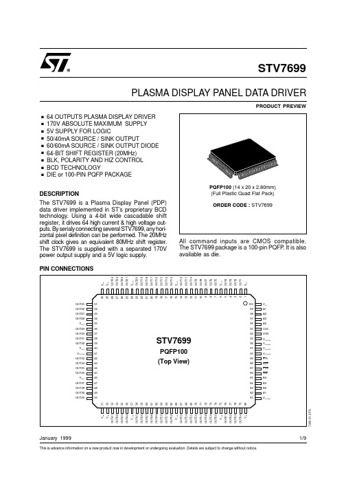
STV7699资料
BOTTOM SIDE from left to right
Name OUT25 OUT26 OUT27 OUT28
VSSP OUT29 OUT30 OUT31 OUT32
VSSP VSSSUB OUT33 OUT34 OUT35 OUT36
VSSP OUT37 OUT38 OUT39 OUT40
Center : X -1443.5 -1249.0 -1049.5 -889.0 -753.0 -614.0 -467.5 -332.0 -186.5 -54.0 78.0 209.5 342.5 467.5 607.5 752.0 892.5 1045.5 1252.0 1433.5
95
CLK
Input Clock of data shift register
Low to High transition makes the data enter into the shift
register and available at the output stage and at the output
Size : x 75.0 75.0 75.0 5.0 75.0 75.0 75.0 75.0 75.0 75.0 75.0 75.0 75.0 75.0 75.0 75.0 75.0 75.0 75.0 75.0
6 - 15 - 24 - 35 - 40 46 - 57 - 66 - 75
VSSP
Ground Ground of power outputs
90 to 93
VSSLOG
Ground Logic Ground
41 - 81
VSSSUB
Ground Substrate Ground
外采清单-东远
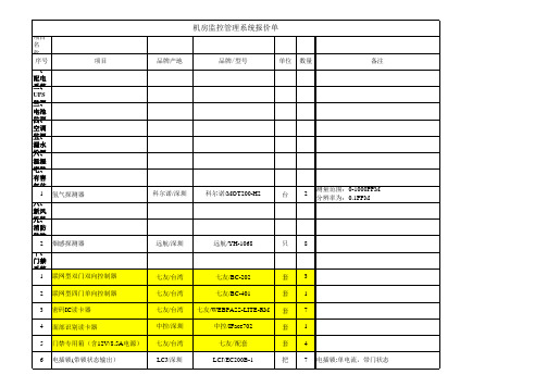
十四、辅助材料 1 2 线管辅材 电源线 国标 用于视频监控设备 批 米 1
十五、中心平台 1 工业计算机(工控机) 研华/深圳 研华/IPC-510-C 套 2 E5300/AIMB-769VG/2G DDR3/SATA 500G/PS-250W/键鼠
2 3 7
操作系统 19寸液晶显示器 声光报警器
7 8 9 10
吸力锁(带锁状态输出) 电锁配件 电锁配件 出门按钮
LCJ/深圳 LCJ/深圳 LCJ/深圳 TCL/深圳
LCJ/MC270L LCJ/PFEC100 LCJ/PUMC270 TCL/TCL
把 套 套 只
2 7 2 8
磁力锁,270千克,带门状态 电插锁U型支架,用于无框玻璃门 磁力锁支架,无框玻璃门
微软 三星/韩国 豪恩/深圳
微软/Windows 7 旗舰版 三星/19寸 豪恩/HC-103
套 套 个2 1 1基本软件功能模块 高级软件功能模块 十六、监控室 1 2 3 4 19寸液晶显示器 4屏监控客户端PC HDMI连接线 监控中心监控台 三星/韩国 HP 三星/E1920NW HP/z400 国标 套 台 条 套 3 1 3 2 图型工作站
十二、可视对讲系统 1 2 3 不联网彩色别墅门口机 彩色免提室内机 专业电源
E-NIKE/深圳 E-NIKE/深圳 E-NIKE/深圳
E-NIKE/LN-DC11 E-NIKE/LNip-RC-15 E-NIKE/LN-PB-4
台 台 台
1 1 1
十三、红外报警系统 1 2 红外吸顶探测器 防盗报警主机 福科斯/深圳 艾礼安/深圳 福科斯/DT-7380 艾礼安/AL-238T 只 台 4 1
十七、费用计算 1 2 合计 最终优惠价
ICP DAS M-7026 多功能数据采集模块说明书
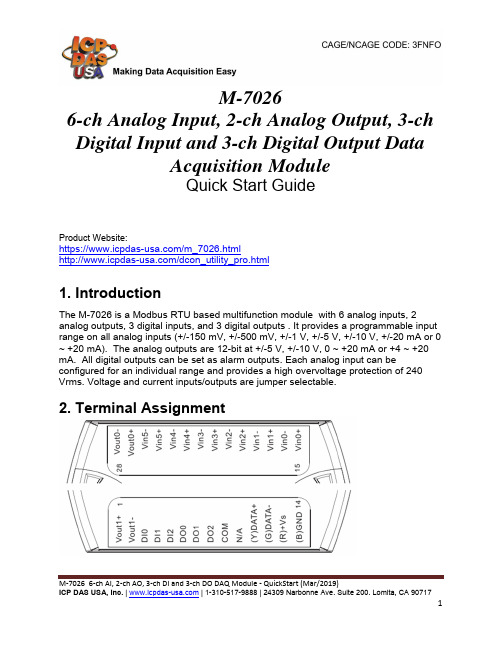
M‐7026 6‐ch AI, 2‐ch AO, 3‐ch DI and 3‐ch DO DAQ Module ‐ QuickStart (Mar/2019)M-70266-ch Analog Input, 2-ch Analog Output, 3-ch Digital Input and 3-ch Digital Output DataAcquisition ModuleQuick Start GuideProduct Website:https:///m_7026.html/dcon_utility_pro.html1. IntroductionThe M-7026 is a Modbus RTU based multifunction module with 6 analog inputs, 2analog outputs, 3 digital inputs, and 3 digital outputs . It provides a programmable input range on all analog inputs (+/-150 mV, +/-500 mV, +/-1 V, +/-5 V, +/-10 V, +/-20 mA or 0 ~ +20 mA). The analog outputs are 12-bit at +/-5 V, +/-10 V, 0 ~ +20 mA or +4 ~ +20 mA. All digital outputs can be set as alarm outputs. Each analog input can beconfigured for an individual range and provides a high overvoltage protection of 240 Vrms. Voltage and current inputs/outputs are jumper selectable.2. Terminal AssignmentM‐7026 6‐ch AI, 2‐ch AO, 3‐ch DI and 3‐ch DO DAQ Module ‐ QuickStart (Mar/2019)3. Block/ Wiring DiagramM‐7026 6‐ch AI, 2‐ch AO, 3‐ch DI and 3‐ch DO DAQ Module ‐ QuickStart (Mar/2019)4. Default SettingsThe default settings for the M-7026 are: ・ Module Address: 01・ Analog Input Type: Type 08, -10 V to +10 V ・ Analog Output Type: Type 3, -10 V to +10 V ・ Protocol: Modbus RTU ・ Baud Rate: 9600 bps ・ Checksum disabled ・ Engineering Units format ・ Filter set at 60 Hz rejectionM‐7026 6‐ch AI, 2‐ch AO, 3‐ch DI and 3‐ch DO DAQ Module ‐ QuickStart (Mar/2019)M‐7026 6‐ch AI, 2‐ch AO, 3‐ch DI and 3‐ch DO DAQ Module ‐ QuickStart (Mar/2019)5. ConfigurationTo install the module, follow the steps below: 1. Connect the thermistor analog input.2. Connect the module to the RS-485 network using the DATA+ and DATA- terminals. If the host is only equipped with an RS-232 interface, then an RS-232 to RS-485 converter will be required.3. Connect the module to the power supply using the +Vs and GND terminals. Note that the voltage supplied should be in the range of +10 to +30V DC.M‐7026 6‐ch AI, 2‐ch AO, 3‐ch DI and 3‐ch DO DAQ Module ‐ QuickStart (Mar/2019)4. Open DCON utility proclick on COM port(first icon).It can select multi-options such as Baud Rate, Protocol, Checksum, and Format to search module. The default settings for the module can be found in Section 3. Click OK after selecting the COM port setting.M‐7026 6‐ch AI, 2‐ch AO, 3‐ch DI and 3‐ch DO DAQ Module ‐ QuickStart (Mar/2019)5. DCON utility pro will search for the selected COM port according the settingpreviously set. DCON Utility Pro supports DCON and Modbus protocol for all ICPDAS and the others modules.6. Configuration I/O module setting on PCM‐7026 6‐ch AI, 2‐ch AO, 3‐ch DI and 3‐ch DO DAQ Module ‐ QuickStart (Mar/2019)7. For M-7000 modules using the Modbus RTU protocol, configure the module using the following functions.・ Sub-function 04h of Function 46h, see user manual Section 3.3.2 ・ Sub-function 06h of Function 46h, see user manual Section 3.3.4・ Sub-function 08h of Function 46h, see user manual Section 3.3.6For M-7000 modules using the Modbus RTU protocol, use Function 04h to read the data from the input channels. See user manual Section 3.2 for details.8. If user doesn’t know command, user can select Address and ID, it will show some refer commands as below. User can select necessary command to test or debug modules.M‐7026 6‐ch AI, 2‐ch AO, 3‐ch DI and 3‐ch DO DAQ Module ‐ QuickStart (Mar/2019)。
Corebai微处理器监控电路操作手册说明书
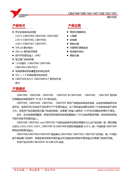
产品特点●修正供电电压监控器2.63V(CBM706P,CBM706R,CBM708R)2.93V(CBM706S,CBM708S)3.08V(CBM706T,CBM708T)●100µA静态电流●200ms复位脉冲宽度●防抖手动复位输入(MR)●独立看门狗定时器● 1.6秒超时(CBM706P,CBM706R,CBM706S,CBM706T)●电源故障或低电量警告的电压监测●VCC=1V时确保复位有效信号●CBM706P/R/S/T,CBM708R/S/T更好的升级能力产品应用●微型处理器系统●计算器●控制器●智能仪器●关键微处理器监控●电源操作系统●便携仪器产品描述CBM706P、CBM706R、CBM706S、CBM706T和CBM708R、CBM708S、CBM708T系列微处理器监控电路适用于3V或3.3V电压监控。
CBM706P、CBM706R、CBM706S、CBM706T系列产品提供有源监控电路,该监控电路能够在电源开启、电源关闭以及电压不足的条件下产生复位输出。
这个复位输出能够在低至1V的供电电源下保持工作。
该系列产品还提供独立看门狗监控电路。
如果看门狗输入能够在1.6秒内没有触发的情况下激活。
此外,还为电源故障警报、低电压检测或附加电源装置提供1.25V的临界值检测器,还包括有效低电平防抖动的手动复位输入。
CBM706R,CBM706S,and CBM706T产品除监视电平的复位阀值外与上述产品功能一致,复位阀值分别为2.63V,2.93V,3.08V。
CBM706P与CBM706R的复位阀值都是2.63V。
唯一不同的是CBM706P 具有自动高复位输出。
CBM708R/CBM708S/CBM708T提供类似CBM706R/CBM706S/CBM706T的功能,唯一不同的是不提供看门狗定时,除提供有效低电平复位输出外还提供有效高电平复位输出代替看门狗定时功能。
所有产品均采用8脚MSOP和8脚SOP封装。
深圳华北工控股份有限公司MATX-6959用户手册V4.0说明书

MATX-6959 USER'Manual V4.0MATX-6959USER'Manual V4.0深圳华北工控股份有限公司:*************北京公司:************上海公司:021-********成都公司:************沈阳公司:************西安公司:************南京公司:************武汉公司:************天津公司:************新加坡公司:65-68530809荷兰公司:31-040-2668554更多产品信息请登陆:声明除列明随产品配置的配件外,本手册包含的内容并不代表本公司的承诺,本公司保留对此手册更改的权利,且不另行通知。
对于任何因安装、使用不当而导致的直接、间接、有意或无意的损坏及隐患概不负责。
订购产品前,请向经销商详细了解产品性能是否符合您的需求。
NORCO 是深圳华北工控股份有限公司的注册商标。
本手册所涉及到的其他商标,其所有权为相应的产品厂家所拥有。
本手册内容受版权保护,版权所有。
未经许可,不得以机械的、电子的或其它任何方式进行复制。
温馨提示1.产品使用前,务必仔细阅读产品说明书。
2.对未准备安装的板卡,应将其保存在防静电保护袋中。
3.在从包装袋中拿板卡前,应将手先置于接地金属物体上一会儿,以释放身体及手中的静电。
4.在拿板卡时,需佩戴静电保护手套,并且应该养成只触及其边缘部分的习惯。
5.主板与电源连接时,请确认电源电压。
6.为避免人体被电击或产品被损坏,在每次对主板、板卡进行拔插或重新配置时,须先关闭交流电源或将交流电源线从电源插座中拔掉。
7.在对板卡进行搬动前,先将交流电源线从电源插座中拔掉。
8.当您需连接或拔除任何设备前,须确定所有的电源线事先已被拔掉。
9.为避免频繁开关机对产品造成不必要的损伤,关机后,应至少等待30秒后再开机。
10.设备在使用过程中出现异常情况,请找专业人员处理。
AMPCI-9102使用说明书

AMPCI-9102数据采集板使用说明书一. 概述AMPCI-9102板是PCI总线通用数据采集控制板,该板可直接插入具备PCI插槽的工控机或个人微机,构成模拟量电压信号、数字量电压信号采集、监视输入和模拟量电压信号输出、数字量电压信号输出及计数定时系统。
AMPCI-9102板为用户提供了单端16路/双端8路模拟量数据采集输入通道, 模拟量输入通道具有程控放大功能,4路12Bit模拟量电压信号输出,16Bit TTL数字量输入和16Bit TTL数字量输出, 6路16位计数定时通道,基准时钟8M,可构成脉冲计数、频率测量、脉冲信号发生器等电路。
对AMPCI-9102板的所有读写操作均为16Bit即D00~D15,当对82C54进行读写时只有D00~D07有效。
二.性能和技术指标•模拟信号输入A/D分辩率12Bit• 16路单端/8路双端模拟信号通道•模拟信号输入具有1/2/4/8倍的程控放大•模拟信号输出D/A分辩率12Bit•模拟信号输出通道4路• 16Bit DI/16Bit DO 数字量输入/输出(74HC电平)• 6路16位计数定时通道• A/D输入电压范围: ±5V(出品状态)、0-10V、±10V•输入阻抗: > 100 MΩ• A/D转换时间: 8.5uS• A/D转换精度: 优于±0.1%•模拟信号输入程控放大倍数: 1/2/4/8•输出电压范围: ±5V(出品状态)、0-5V、0-10V•计数定时部分: 16BIT /6通道三. AMPCI-9102软件安装WIN2000/XP 环境下AMPCI-9102安装说明软件运行环境包括Windows2000和WindowsXP软件安装过程1、将AMPCI-9102卡插入到主机的某一PCI插槽内。
2、启动Windows/2000或Windows/XP。
3、当出现“添加新硬件向导”对话框时,将带有驱动程序的光盘放入光驱,并选择“下一步”;在随后出现的对话框中,选择或输入光盘的g:\ ampci-9102\ 9102win2k\Pcisdk.inf文件。
研华工控机手册

User ManualMIC-3042A/B4U高、8槽、配有标准cPCI电源的CompactPCI TM机箱版权声明随附本产品发行的文件为研华公司2008年版权所有,并保留相关权利。
针对本手册中相关产品的说明,研华公司保留随时变更的权利,恕不另行通知。
未经研华公司书面许可,本手册所有内容不得通过任何途径以任何形式复制、翻印、翻译或者传输。
本手册以提供正确、可靠的信息为出发点。
但是研华公司对于本手册的使用结果,或者因使用本手册而导致其它协力厂商的权益受损,概不负责。
认可声明PICMG TM、 CompactPCI TM和PICMG TM、CompactPCI TM标志是 PCI工业计算机制造厂商协会的注册商标。
所有其他产品名或商标均为各自所属方的财产。
CE本设备已通过CE 测试,符合以屏蔽电缆进行外部接线的环境规格标准。
建议用户使用屏蔽电缆,此种电缆可从研华公司购买。
如需订购,请与当地分销商联系。
产品质量保证(一年)从购买之日起,研华为原购买商提供一年的产品质量保证。
但对那些未经授权的维修人员维修过的产品并不进行质量保证。
研华对于不正确的使用、灾难、错误安装产生的问题有免责权利。
如果研华产品出现故障,在质保期内我们提供免费维修或更换服务。
对于出保产品,我们将会酌情收取材料费、人工服务费用。
请联系您的销售人员了解详细情况。
如果您认为您购买的产品出现了故障,请遵循以下步骤:1.收集您所遇到的问题的信息(例如,CPU主频、使用的研华产品及其它软件、硬件等)。
请注意屏幕上出现的任何不正常信息显示。
2.打电话给您的供货商,描述故障问题。
请借助手册,产品和任何有帮助的信息。
3.如果您的产品被诊断发生故障,请从您的供货商那里获得RMA(ReturnMaterial Authorization)序列号。
这可以让我们尽快的进行故障产品的回收。
4.请仔细的包装故障产品,并在包装中附上完整的售后服务卡片和购买日期证明(如销售发票)。
Agilent I O Hardware 数据手册说明书

82357A technical specificationsGeneral requirementsMinimum system requirements Windows 98(SE)/Me 2•PCI IEEE-488 interface for PCs•Transfer rates up to 900 KB/s•Dual processor support onWindows 2000/XPBest for•Maximum GPIB throughput forall configurationsHigh performance for manufacturingtest applicationsThe 82350B is Agilent’s highest-performance GPIB interface. Witha direct PCI computer connection,transaction overhead is minimizedfor the best overall performance.The 82350B card de-couples GPIBtransfers from PCI bus transfers.Buffering provides I/O and systemperformance that is superior to directmemory access (DMA). The hardwareis software configurable and compati-ble with the Plug-and-Play standardfor easy hardware installation. TheGPIB interface card plugs into a 5 voltPCI slot in the backplane of your PC.For programming capability youhave access with the latest versionof IO Libraries suite, version 14.1, toprogram in all standard developmentenvironments. Agilent’s IO LibrariesSuite 14.1 is easy to use and workswith virtually any vendor’s instrumentor T&M programming softwareapplication and includes automaticconfiguration for Agilent or NI VISA,NI-488.2, VISA COM or T&M ToolkitDirect IO. Even if you use NI IO soft-ware Agilent will configure automati-cally so as a user you do not have tobe concerned with the behind-the-scenes details.382350B technical specifications General requirements Minimum system requirements Windows 98(SE)/Me (note 98 supported with version 14.0 only)/2000/XP Software required Agilent IO Libraries Suite (included); see requirements on page 1PCI bus slot 5-V PCI slot, 32 bits Supported standards PCI rev 2.2IEEE 488.1 and IEEE 488.2 compatible General characteristics Power Backplane +5 V PCI Connectors Standard 24-pin GPIB (IEEE-488)+5V PCI Maximum data rate More than 900 KB/s Maximum instrument connection 14 instruments—daisy chain via GPIB Buffering Built-in Configuration Plug-and-Play EMC and safety *IEC 61326-1Group 1, Class A IEC 61010-1Warranty 1 year Dimensions Length, width, and height 122 mm (L) x 122 mm (W) x 22 mm (H) (a full-height PCI card)Weight 0.091 kg Environmental specifications Operating environment 0°C to 55°C Operating humidity Up to 90% at 40°C non-condensing Storage environment -40°C to +70°C Storage humidity Up to 90% at 65°C non-condensing * Additional detail and information in the Declaration of ConformityThis traditional GPIB connection still offers the highest throughputE5810A technical specifications 45USB port on your PC to up to fourRS-232 instruments or devices•Fully compatible with WindowsCOM driver and industry-standardVISA I/O software.Best for•Easy connection to RS-232 devices•Notebook computer RS-232connectionsAdd four serial ports in minutesThe Agilent E5805A USB/4-portRS232 interface provides a directconnection from the USB port onyour notebook or desktop PC to up tofour RS-232 instruments or devices.There are no switches to set, no PCcards to install, and no external powersupplies are required. Simply installthe driver and plug in the E5805AUSB 4-port RS232 interface to addfour RS-232 ports to your computer.Since the E5805A is a standardPlug-and-Play device, your computerautomatically detects and configuresit when it is connected to your com-puter USB port. You can interface upto four devices, with baud rates up to230 Kb/s per serial port. The E5805Aprovides four DB9 serial connectorsand ships with a 1.8-meter USB cable.E5813A technical specificationsGeneral requirements67Agilent Technologies’ Test and Measurement Support, Services, and Assistance Agilent Technologies aims to maximize the value you receive, while minimizing your risk and problems. We strive to ensure that you get the test and measurement capabilities you paid for and obtain the support you need. Our extensive support resources and services can help you choose the right Agilent products for your applications and apply them successfully. Every instru-ment and system we sell has a global warranty. Support is available for at least five years beyond the production life of the product. Two concepts underlie Agilent’s overall support policy: “Our Promise” and “Your Advantage.”Our Promise Our Promise means your Agilent test and measurement equipment will meet its advertised performance and functionality. When you are choosing new equipment,we will help you with product information, including realistic performance specifications and practical recom-mendations from experienced test engineers. When you receive your new Agilent equipment, we can help verify that it works properly, and help with initial product operation.Your AdvantageYour Advantage means that Agilent offers a wide range of additional expert test and measurement services, which you can purchase according to your unique technical and business needs. Solve problems efficiently and gain a competitive edge by contracting with us for calibration, extra-cost upgrades, out-of-warranty repairs, and onsite education and training, as well as design, system integration, project management, and other professional engineering services. Experienced Agilent engineers and techni-cians worldwide can help you maximize your productivity,optimize the return on investment of your Agilent instruments and systems, and obtain dependable measurement accuracy for the life of those products./find/emailupdates Get the latest information on the products and applications you /find/openAgilent Open simplifies the process of connecting and programming test systems to help engineers design,validate and manufacture electronic products. Agilentoffers open connectivity for a broad range of system-ready instruments, open industry software, PC-stan-dard I/O and global support, which are combined to more easily integrate test system development. For more assistance with your test & measurement needs or to find your local Agilent office go to /find/contactus Microsoft, Windows and Visual Studio are U.S. registered trademarks of Microsoft Corporation.Pentium is a U.S. registered trademark of Intel Corporation.Product specifications and descriptions in this document subject to change without notice.© Agilent Technologies, Inc. 2005Printed in USA, August 5, 20055989-1889EN Agilent Open Agilent Email Updates •Agilent E2094N IO Libraries Suite, Data sheet pub no. 5989-1439EN •Modern Connectivity–Using USB and LAN I/O Converters, Application note 1475-1pub no. 5989-0123EN •Simplified PC Connections for GPIB Instruments,Application note 1409-1, pub no. 5988-5897EN •Using LAN in Test Systems: The Basics,Application note 1465-9, pub no. 5989-1412ENpub no. 5989-1417EN •Computer I/O Considerations, Application note 1465-2, pub no. 5988-9818EN Learn more at /find/io-ds Join the Agilent Developer Network to get updated I/O software, instrument drivers, code examples,white papers, and more! Registration is easy and free at /find/adn.。
- 1、下载文档前请自行甄别文档内容的完整性,平台不提供额外的编辑、内容补充、找答案等附加服务。
- 2、"仅部分预览"的文档,不可在线预览部分如存在完整性等问题,可反馈申请退款(可完整预览的文档不适用该条件!)。
- 3、如文档侵犯您的权益,请联系客服反馈,我们会尽快为您处理(人工客服工作时间:9:00-18:30)。
AIMB-769 Startup Manual 1
Before you begin installing your card, please make sure that the following items have been shipped:
• AIMB-769 A TX IMB
• 1 AIMB-769 Startup Manual
• 1 Driver CD (user’s manual is included)• 2 Serial AT A HDD data cables • 1 Serial AT A HDD power cable • 1 I/O port bracket • 1 jumper package • 1 warranty card
If any of these items are missing or damaged, please con-tact your distributor or sales representative immediately. Note:
Acrobat Reader is required to view any PDF file. Acrobat Reader can be downloaded at: /Products/acrobat/readstep2.html (Acrobat is a trademark of Adobe)
Standard SBC Functions
• CPU: LGA775 Intel ®
Core™ 2 Quad/Core™ 2 Duo/Penti-um ® Dual Core/Celeron ®
• BIOS: AMI 16 Mb SPI BIOS • FSB: 800/1066/1333 MHz • Chipset: G41 with ICH7
• System memory: Up to 4 GB with two 240-pin DIMM sockets. Supports dual channel DDR3 800/1066 SDRAM.
Note: Due to the inherent limitations of PC architecture,
the system may not fully detect 4 GB RAM when 4 GB RAM is installed.• SATA II Interface: Four on-board serial SA TA II connec-tors with a data transmission rate of up to 300 MB/s and supporting Advanced Host Controller Interface (AHCI) technology.
AIMB-769 Socket LGA775 Intel ® Core™2 Quad ATX with VGA, 2 COM, Single LAN Startup Manual
• FDD interface: Supports one FDD
• Serial ports: T wo RS-232 serial ports with DC power (+5 V or +12 V) support for industrial applications.
• Keyboard/mouse connector: Supports standard PS/2 keyboard and mouse.
• Watchdog timer: 255 level timer intervals.• USB 2.0: Supports up to eight USB 2.0 ports.
VGA Interface
• Chipset: Chipset integrated VGA controller.
• Display Memory: Dynamically shared system memory up to 352 MB.
• Resolution: Up to resolution 2048 x 1536 @ 75 Hz refresh rate.
Ethernet interface
• Interface: 10/100/1000 Base-T
• Controller: LAN1: REALTEK RTL8111G-CG
Mechanical and Environmental
• Dimensions (L x W): 304.8 x 228.6 mm
• Power supply voltage: +3.3 V, +5 V, ±12 V, 5 VSB
• Power requirements: Maximum: +5 V at 1.76 A, +3.3 V at 2.28 A, +12 V at 4.7 A, 5 VSB at 0.19 A, (Intel ® Core ™ 2 Quad Q9650 3.0 GHz, two 1GB DDR3 1066 MHz SDRAM)
• Operating temperature: 0 ~ 60 °C (depending on CPU)• Weight: 0.5 Kg (weight of board)
The board has a number of jumpers that allow you to con-figure your system to suit your application. The table below lists the function of each of the jumpers and connectors.For more information on this and other Advantech products, please visit our website at:
/intelligent-systems For technical support and service, please visit our support website at:
/support
This manual is for the AIMB-769 series Rev. A2Part No. 2006076911
2nd Edition October 2014
2 AIMB-769 Startup Manual
The CD disc contains programs that will lead you through the installation of various device drivers needed to take full advantage of your motherboard.
The computer is supplied with a battery-powered realtime clock circuit. There is a danger of explosion if battery is incorrectly replaced. Replace only with same or equivalent type recommended by the manufacturer. Discard used bat-teries according to manufacturer’s instructions.
This device complies with the requirements in Part 15 of the FCC rules. Operation is subject to the following two conditions:
1. This device may not cause harmful interference.
2. This device must accept any interference received,
including interference that may cause undesired operation.
Software Installation
Declaration of Conformity
Keep CMOS data Clear CMOS data
A
AIMB-769 Startup Manual 3
Figure 1: Board Layout - Jumper and Connector Locations
PCIe x16
SATA 1~4
SYSFan 1
Floppy JWDT1+JOBS1
PSON1
IR_CON EA TXPWR1FPAUD1。