扭矩倍增器用户手册
倍力器说明书

当手动施加扭矩时,方向与输出端方驱的旋转方向相反,反作用力臂必须静止直角地对准 一个坚固物体或附近表面,以便锁紧螺栓(如图2)
如标准的反作用力臂不适合现在工作环境,请联络NORBAR公司或当地NORBAR经销商。
HANDTORQUE MULTIPLIERS OPERATORS HANDBOOK
顺时针操作
Norbar Torque Tools
全球扭矩工具的领导者
手动扭矩倍增器
HANDTORQUE MULTIPLIERS 中文操作手册
(PART No. 34269)
诺霸精密机械(上海)有限公司 地址:上海市宜山路1618号E栋5楼 电话:021-61450368 传真:021-61450369 www.norbar.com.cn
顺时针方向操作/上锁螺丝
中立位置
逆时针方向操作/卸锁螺丝
请拨动反回弹装置D;确认已选择了所需的操作方向。
警告:当内部棘轮转动不灵活时,不能使用本倍增器。 2. 按照操作手册施加扭矩并按预先设定扭矩值操作倍增器。
HANDTORQUE MULTIPLIERS OPERATORS HANDBOOK
PAGE 4 OF 12
操作步骤
注意:操作之 前,请阅读此操作手册
在7-12页介绍如何使用反回弹棘轮装置的倍增器。
扭矩倍增器是一种精密的工具,把输入的扭矩以正确的倍率放大。操作扭矩倍增器需要
以下装备:
动力装置或高级的冲击式套筒
PAGE 1 OF 12
页数 2 3 4 4 6 6 6 7 7 7 9 11
HANDTORQUE MULTIPLIERS OPERATORS HANDBOOK
PAGE 2 OF 12
适用型号
DTT-L系列数字扭矩测试仪用户手册说明书

User ManualTable of ContentsService and Warranty (3)Overload Capacity Caution (3)System Overview (3)Battery Chargers (5)Standard Equipment (5)Instructions for Using the Driver Adapter (6)Usage (7)Procedure for Manual Torque Screwdrivers (7)Procedure for Power Screwdrivers (7)Battery Indicator (8)Basic Function (8)Display of Clockwise/Counter-Clockwise (8)Zeroing the Tester (9)Changing the Unit of Measure (9)Changing the Mode of Measure (9)Backlit Display (10)Saved Reading to Memory (10)Main Menu (10)Setting (10)Auto-Shutdown (11)Auto-Reset (11)Pass-Fail (12)Load Default (13)Memory (13)View (13)Delete Last (14)Delete All (14)Calibration (14)Transducer State (15)About (15)Service and WarrantyOverload Capacity CautionASG, Division of Jergens, Inc., warrants to the original purchaser buying the ASG DTT-L meter with the intention of use rather than resale, for a period of 1 year. ASG will replace those items found to be defective or otherwise fail to conform, or at ASG’s option repay the price paid for the item. The buyer’s remedies with respect to any item found to be defective or otherwise not conforming shall be limited exclusively to the right of replacement or repayment. In no event shall ASG be liable for any incidental, special or consequential damages or for damages in the nature of penalties.DISCLAIMER: Seller makes no other warranty what-so-ever, expressed or implied, and all implied warranties of merchantability and fitness for a particular purpose are disclaimed and excluded from this transaction and shall not apply to the goods sold hereunder. The ASG DTT-L meter is an electronic instrument and should be treated with the same care given any sensitive electronic instrument. Avoid dropping the unit or dropping items on the unit. Avoid high shock loads to the transducer. Use the proper driver adapter when using clutch type power tools.Do not exceed the capacity of the unit. The overload capacity of a DTT-L meter is 200% of its maximum load capacity. If the meter is taken over capacity, a warning tone will sound, the word “OVERLOAD ” will flash on the LCD, and the unit will LOCK until the RESET button is pressed. Immediately stop applying torque when the overload warnings are observed. A unit subjected to overload or subjected to harsh conditions, such as use with an impact tool, will not be covered under warranty.System OverviewSystem Overview (Continued)* DTT-200 and DTT-500 come with mounting plateStandard EquipmentAll DTT-L meters are supplied with the following standard items: • DTT-L torque meter• Battery charger/Power adapter• NOTE: Rundown adapters sold separately; International charger also sold separatelyBattery Chargers9 Volt, 500 mA, 90-264 VDC US Power Adapter (Supplied)9 Volt, 670 mA, 90-264 VDC International Power Adapter (Optional, Must Order Separately)ASG #66603ASG #66619Instructions for Using the Rundown AdaptersBelow is a list of all rundown adapters ASG offers for the DTT and DTT-L Series• Rundown adapters are included with the DTT torque testers. See charts in DTT manual on page 6 for more information. • Rundown adapters are not included with the DTT-L torque tester, choose the needed rundown adapters from the chart belowwhen ordering the tester.* ASG Adapter #66612 comes with two springs covering torque range from 1.3-5.0 lbf.in (0.15-0.56) and 4.5-26.0 lbf.in (0.51-2.94 N.m)ASG #66620ASG #66631ASG #66612ASG #66633ASG #66635ASG #66618ASG #66639ASG #66634ASG #66617ASG #66642UsageProcedure for Manual Torque Drivers• Attach a proper adapter to connect the driver to the 3/8” female square.• NOTE: It is NOT recommended to use the power tool adapters to calibrate hand torque tools.• Select FIRST PEAK mode using the MODE button. Press the RESET button if the display is not at 0.• Turn the driver or wrench clockwise or counterclockwise until the “break” point is reached.• In FIRST PEAK no other reading can then be displayed until the reset button is pressed.• The LCD display will show the torque that the driver or wrench is set at. Note the reading or write it down. To enter it into the DTT-L memory press the ENTER/MEM button. If you are testing several tools, note the memory numbers of the readings for the various tools. This number is in the upper right hand corner of the LCD. The unit can save up to 200 readings. After that, no further readings can be entered until the memory is cleared.• If the torque is not correct, adjust the tool. Repeat the test. When the reading is proper, perform the test several times to be sure the readings are consistent. The proper reading may be an average of several readings.Procedure for Power Screwdrivers• Put the appropriate rundown adapter into the unit’s female 3/8” square socket. It allows the power tool to reach its working speed before tightening up and causing the clutch to operate.• Run the tool in reverse to make sure the adapter is unwound. Do not disassemble the driver adapter.• Make sure the unit is in PEAK mode. If it is not, use the MODE button to select PEAK mode.• Press the ZERO button to be sure the display is at 0.• Run the tool forward until it shuts off. The reading on the display will be the torque setting of the tool’s clutch. Note the reading or write it down.• To enter it into the units memory, press the ENTER/MEM button. If you are testing several tools, note the memory numbers of the readings for the various tools. This number is in the upper right hand corner of the LCD. The unit can save up to 200 readings. After that no further readings can be entered until the memory is cleared.• If the torque is not correct, adjust the clutch. Repeat the test. When the reading is proper, perform the test several times to be sure the readings are consistent. The proper reading may be an average of several readings.• Always unwind the rundown adapter after each test. Do NOT leave the spring under tension while not in use.Battery IndicatorBasic FunctionDisplay of Clockwise/Counter-ClockwiseBatteryBattery Level > 5.00V 4.99V > Battery Level > 4.8V 4.79V > Battery Level > 4.7V 4.69V > Battery Level > 4.65V Battery Level < 4.65Vrecognized by the symbol “CCW.”Clockwise symbolLoad indicator bar for clockwiseLoad indicator clockwiseCounter-clockwise symbolA load indicator bar alerts the operator as to how much torque load is being applied to the transducer as related to its full scale rating.Before using the unit, make sure the battery has been charged. If the battery is low, the LCD may not function. If the battery dies during use, the on/off switch will need to be cycled to use the unit after the charger is connected. Allow the battery to fully charge then detach the charger. CAUTION: If the battery overheats during charging a thermal fuse will open. The unit will not operate until the fuse resets. Allow the DTT meter to sit for up to 30 minutes with the charger disconnected then turn the unit back on.If the battery level is less than 4.6 V , the “Battery Empty ” message will be displayed and the tester will power down automatically. When battery charger is connected and battery is charging, the plug icon will blink. NOTE: Only use the 9V adapter/charger supplied. The supplied charger is a battery charger only. It is not to be used as an AC adapter to power the DTT meter in place of using the batteries in normal operation.While operating the tester, it may be necessary to zero the display so that residual torque does not become part of the measured reading. Press and release the ZERO key.You can choose from the following modes of measure: Track, First Peak, and Peak . To change the display mode, press the MODE key. Each time the MODE key is pressed, it will select the next available mode until the tester returns to its original setting.You can choose from the following units of measure depending on the capacity of your tester: N.mm (not available on the DTT-L 500), N.cm, N.m, kgf.cm, kgf.m, lbf.in, and lbf.ft. To change the display units, press the UNIT key. Each time the UNIT key is pressed, it will select the next available unit until the tester returns to its original setting. The DTT-L automatically converts readings as new units of measure are selected.NOTE: All units may not be displayed depending on tester capacity.Basic Function (Continued)Zeroing the TesterChanging the Mode of MeasureChanging the Unit of MeasurePress the MODE key until “Track” appears on the display. The display will now indicate the torque applied in either direction as it is applied to the transducer.Press the MODE key until “Peak” appears on the display. The display will show the maximum torque applied to the transducer during a cycle.Press the MODE key until “FPeak” appears on the display. The display will show the torque level applied to the transducer.Track ModePeak ModeFirst Peak ModeAny reading can be saved anytime by pressing the MEM key. A total of 200 readings can be stored in the database including the reading unit.Basic Function (Continued)Saved Reading to MemoryWhen you press any key or apply torque to the transducer greater than 0.5% of full scale, the backlight will go on for 60 seconds.Backlit Display• To access the SETTING menu, press the MENU/ESC key. Use the UP or DOWNARROW keys to move the cursor to SETTING . Press ENTER.• To move between the submenus listed in the SETTING menu, press the UP orDOWN ARROW keys to move the cursor. The sub-menus in the setting menu are auto-shutdown, auto-reset, pass-fail, and load default.• Press ENTER to select the sub-menus, activate feature and enter values. Withinsub-menus the UP , DOWN , LEFT and RIGHT ARROW keys will also change numerical values.• Press ESC to return to the setting menu pageSettingMain Menu• Press the MENU/ESC key to access the main menu• To move between the sub-menus listed on the main menu page, press the UP orDOWN ARROW keys to move the cursor • Press ENTER to select the sub-menus, activate features and enter values.Within sub-menus, UP , DOWN , LEFT and RIGHT ARROW keys will also change numerical values.• Press ESCto return to the main menu pageThe Auto-Reset feature is used to automatically reset the reading value in peak mode. This mode works when the reading value is higher than the setting value, causing the peak value to change to a new held value. The user does not need to press the RESET key, since the peak value will automatically reset. This feature works in peak mode only. If this feature is activated, the icon “AR” will display on main display.• To set Auto-Reset, press the MENU/ESC key, the display will show the main menu page. Use the UP and DOWN ARROW keys to move the cursor point to SETTING . Press the ENTER key and use the UP and DOWN ARROW keys to move the cursor point to A UTO-RESET . Press the ENTER key. The display will show the Auto-Reset menu page.• Press the ESC key to return the main menu page• Use the UP and DOWN ARROW keys to change the value. Use the RIGHT ARROW key to change the unit. Press ZERO key to reset value to zero. Press ENTER key to set new value and return to setting menu. Press ESC to return to setting menu.• Auto-Reset feature will automatically be disabled if you set AUTO-RESET = 0• To set Auto-Shutdown, press the MENU/ESC key, the display will show the main menu page. Use the UP and DOWN ARROW keys to move the cursor point to SETTING . Press the ENTER key and use the UP and DOWN ARROW keys to move the cursor point to AUTO-SHUTDOWN . Press the ENTER key. The display will show the Auto-Shutdown menu page.• The Auto-Shutdown feature can be enabled to conserve battery power where the meter powers down after 5, 10, and 15 minutes (depending on auto-shutdown time) since the last key press. Use the UP and DOWN ARROW keys to move the cursor to the auto-shutdown time preferred and press ENTER.• Press ESC key to return to the main menu page. If you activate this feature, the OFF symbol will be displayed on the main display.Auto-ResetAuto-ShutdownMain Menu (Continued)Main Menu (Continued)The pass-fail feature is used to set a defined acceptable maximum and minimum torque range for measuring. It is activated by setting the lower level and upper level torque limit. As long as the torque value is within this range, the green LED display button will light up OK. Any reading values outside this range (higher or lower), the orange LED display buttons will light up. The orange up arrow will light up if the torque range is higher than the set range and the orange down arrow will light up if the torque range is lower than the set range. If this feature is activated, the PF symbol will display on the main display.• To access the Pass-Fail menu, press the MENU/ESC key, the display will show the main menu page. Use the UP and DOWN ARROW keys to move the cursor point to SETTING . Press the ENTER key and use the UP and DOWN ARROW keys to move the cursor point to PASS-FAIL . Press ENTER . The display will show the Pass-Fail menu page.• Press the ESC key to return the main menu page• Use the UP and DOWN ARROW keys to change the value. Use the RIGHT ARROW key to change the unit. Use the LEFT ARROW key to toggle between the upper and lower limits. Press the ZERO key to reset value to zero. Press the ENTER key to set new value and return to setting menu. Press ESC to return to setting menu.NOTE: Lower level must be less than the upper levelPass-FailMain Menu (Continued)MemoryThis is used to view the saved record, delete the last record, or delete all records.• To access the Memory menu, press the MENU/ESC key, the display will show the main menu page. Use the UP and DOWN ARROW keys to move the cursor point to MEMORY . Press the ENTER key. The display will show the Memory menu page.• In this sub-menu, memory is able to be viewed, delete last, or delete all • Press the ESC key to return to the main menu pageViewLoad DefaultThis is used to view all saved records in memory. The detail of each saved record consists of mode, reading value with unit, and direction.• To access the View menu, press the MENU/ESC key, the display will show the main menu page. Use the UP and DOWN ARROW keys to move the cursor point to MEMORY . Press the ENTER key. Press the UP and DOWN ARROW keys to move the cursor point to VIEW and press the ENTER key.• Use the UP and DOWN ARROW keys to scroll through the readings • Press the ESC key to return to the memory menu pageThe Load Default setting is used to restore the auto-shutdown, auto-reset, and pass-fail to its original setting. These features will all be turned off.• To access the Load Default menu, press the MENU/ESC key, the display will show the main menu page. Use the UP and DOWN ARROW keys to move the cursor point to SETTING . Press the ENTER key. Press the UP and DOWN ARROW keys to move the cursor point to LOAD DEFAULT and press the ENTER key.• Press the ENTER key to reset to default settings• Press the ESCkey to return the main menu pageMain Menu (Continued)Delete AllCalibrationThis is used to delete all saved records.• To access the Delete All menu, press the MENU/ESC key, the display will show the main menu page. Use the UP and DOWN ARROW keys to move the cursor point to MEMORY . Press the ENTER key. Press the UP and DOWN ARROW keys to move the cursor point to DELETE ALL and press the ENTER key. Press the UP or DOWN ARROW keys to move the cursor point to DELETE ALL and press the ENTER key. The display will show the Delete All menu page.• Press the ESC key to return to the memory menu page• Press the UP or DOWN arrow keys to select NO or YES . If you select NO and press the ENTER key, the meter will return to the memory menu page. If you select YES and press the ENTER key, the meter will delete all saved records andreturn to the memory menu page.Delete LastThis is used to delete the last saved record.• To access the Delete Last menu, press the MENU/ESC key, the display will show the main menu page. Use the UP and DOWN ARROW keys to move the cursor point to MEMORY . Press the ENTER key. Press the UP and DOWN ARROW keys to move the cursor point to DELETE LAST and press the ENTER key. The display will show the Delete Last menu page.• Press the ESC key to return to the memory menu page• Press the UP and DOWN ARROW keys to select NO or YES . If you select NO and press the ENTER key, the monitor will return to the memory menu page. If you select YES and press the ENTER key, the meter will delete the last saved recordand return to the memory menu page.ASG service technicians to calibrate the meter; please contact ASG for additional calibration information.Main Menu (Continued)AboutThis shows the information regarding your tester (model, capacity, firmware revision, serial number).• To access the About menu, press the MENU/ESC key, the display will show main menu page. Use the UP and DOWN ARROW keys to move the cursor point to ABOUT . Press the ENTER key. The display will show the ABOUT menu page.• Press the ESC key to return to the main menu pageTransducer StateThis is used to check the status of the transducer. If you suspect that your transducer has sustained an overload, check the status of the transducer immediately. To access the Transducer State menu, press the MENU/ESC key, the display will show main menu page. Use the UP and DOWN ARROW keys to move the cursor point to TRANSDUCER STATE . Press the ENTER key. Press the UP and DOWN ARROW keys to move the cursor point to VIEW and press the ENTER key.• Place the meter horizontally on a flat level surface and go to the main menu page • Use the UP and DOWN ARROW keys to move the cursor point to TRANSDUCER STATE and press the ENTER key• The display will show the TRANSDUCER STATE menu page. Press the ESC key to return to the main menu page• If the % offset is greater than 10%, please contact ASG to arrange for evaluation • Transducer state offset number is for reference only and does not determine whether the transducer is yielded• These values are given only as an indicator – the need for repair may varyaccording to the individual characteristics of the transducer。
M18 FUEL 高扭力扭矩扳手用户操作手册说明书

•Stay alert, watch what you are doing and use be performed. Use of the power tool for operations
common sense when operating a power tool. Do different from those intended could result in a hand bystanders away while operat-
POWER TOOL USE AND CARE
ing a power tool. Distractions can cause you to lose •Do not force the power tool. Use the correct
eye protection. Protective equipment such as a dust mask, non-skid safety shoes, hard hat or hearing protection used for appropriate conditions will reduce personal injuries.
follow all instructions listed below may result in
Save all
warnings and instructions for future reference.
The term "power tool" in the warnings refers to your
mains-operated (corded) power tool or battery-oper-
turning the power tool on. A wrench or a key left attached to a rotating part of the power tool may result in personal injury. •Do not overreach. Keep proper footing and balance at all times. This enables better control of the power tool in unexpected situations. •Dress properly. Do not wear loose clothing or jewelry. Keep your hair and clothing away from moving parts. Loose clothes, jewelry or long hair can be caught in moving parts.
力矩倍增器使用说明书
2.3在使用过程中,用手按住输出端套筒部分;
2.4使用完成后,清洁力矩放大器和力矩输入杆,并将一切值清零,放置于专用盒内。
力矩对照表:
输入
55
62
70
82
101
112
123
134
输出பைடு நூலகம்
539
608
686
804
991
1098
1206
力矩倍增器使用说明书
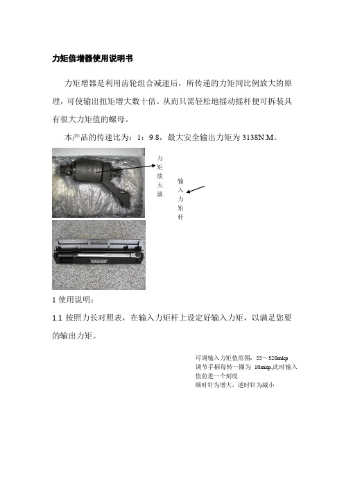
力矩增器是利用齿轮组合减速后,所传递的力矩同比例放大的原理,可使输出扭矩增大数十倍。从而只需轻松地摇动摇杆便可拆装具有很大力矩值的螺母。
本产品的传速比为:1:9.8,最大安全输出力矩为3138N.M。
1使用说明:
1.1按照力长对照表,在输入力矩杆上设定好输入力矩,以满足您要的输出力矩。
在力矩放大器上还有一个撑脚,在使用时必须将撑脚阁置在相邻螺栓上。由相邻螺栓给其一个阻力,力矩放大器克服阻力产生扭矩,达到紧固或拆卸螺栓的目的。
当螺栓坚固或拆完成后,不能使用强力将套筒取出,必须将放大器上力矩方向指针打到O位置,随即放大器会自动回力,从而轻意将套筒取出。
1.4在放大器输入端,有一个高强度销钉,它将力矩输入端与力矩放大器连接起来,使输入端与放大器相对静止。由于它受力,所以在使用前必须对其进行检查,如有裂纹需即时更换。
1.5在使用过程中,用手握住力矩输出端与套筒连接处,以防止在使用过程中因撑脚卡位脱落飞出。手握方向与撑脚阻力方向相反,以防止撑脚飞出后伤手。
1.6使用完成后,将力矩放大器放到专用盒里,并将力矩方向指针打到O位置。将输入力矩杆的值调到零,放入专用盒中。
2注意事项:
FHT4500中文

法速博扭力倍增器使用说明书订货号:FHT4500请对照英文说明书示意图!一、 收货清单1.扭力倍增器1台2.板式反作用力臂1个3.L型反作用力臂1个4.棘轮扳手1把5.六角螺丝1套6.内六角扳手1支7.英文说明书1册二、 安全事项1.危险:高空吊装请注意人员站立位置;小心棘轮扳手受反弹力而伤害人身安全;2.警告:1)使用前仔细阅读说明书;2)切勿使用气动、电动扳手驱动;3)找准合适的反作用力臂支点;4)切勿拿锤子拨动旋转方向杆;5)在使用中,小心手在反力臂支点的安全;6)驱动方轴一定要完全插入套筒四方口;7)不能使用套筒转换方头;8)使用时要穿戴符合安全规程的防护服装;三、 规格参数1.输出力矩范围:1500-4500N.M2.允许输入力矩范围:110-331N.M3.扭矩放大比:13.64.输入方寸:3/4″5.输出方寸:1-1/2″6.重量:12.9KG7.力矩精度:±58.锁紧与拆松(正反转):均可以四、 使用前的准备事项1.根据螺栓规格及预紧力矩确定输入力矩:如8.8级的M48的锁紧力矩为3136N.M,那么输入力矩= 3136 / 13.6=231N.M2.根据螺栓工况选择合适的反作用力臂:当选择L型反力臂时,先用内六角扳手拆下板式反力臂,再装上L型反力臂,然后拧紧螺丝。
五、使用方法重要事项:扭力倍增器的旋转方向L或R必须与棘轮扳手(力矩扳手)的旋转方向保持一致,忽视这一点会造成内部挡销损坏,不在质保范围;1.锁紧螺栓:将棘轮扳手的方向扭拨向右边,将扭力倍增器的黄色拨动杆拨向R,选择合适的反力臂作用点(或相邻螺栓等),按图示转动棘轮扳手,直到锁紧;2.拆松螺栓:将棘轮扳手的方向扭拨向左边,将扭力倍增器的黄色拨动杆拨向L,选择合适的反力臂作用点(或相邻螺栓等),按图示转动棘轮扳手,直到锁紧;3.当出现因为螺栓受力不均而出现反作用力臂卡死情况时,按图中方向拨动黄色拨杆,直至取下扳手。
数字扭矩仪使用说明书

数字扭矩仪使用说明书Ver 0.01SHIMPO1.本产品的特点z可以测得开栓方向或闭栓方向的扭距z可以用USB向电脑传输数据z可以测得峰值(峰值保持)z存储功能可以最多存储1000个计测时的峰值。
z比对功能可以判断产品的合格与否(判定结果通过LED显示)z由于采用了镍氢电池,没有AC适配器也可以方便地使用。
z额定扭距为2N、5N、10N的机种。
z可以切换为各种单位(国内只可以转换)z计测周期(显示周期)最大可从8次/秒中选择。
2.各部分名称及工作2.1主机部分■ (前面)①Power键键键键键⑥液晶显示部分①Power キー用于电源的开/关②Recall キー开栓计测或闭栓计测模式时读取已存储的数据※平均计测模式时不能读取存储数据。
用于功能模式时③Mem キー在开栓计测或闭栓计测模式下将保持峰值输入、存储。
※平均计测模式下不能存储输入。
用于存储数据完全清除时用于功能模式时。
④Mode キー切换计测模式。
读取存储数据时按本按钮会返回计测模式。
在功能模式时使用。
⑤Zero/RST キー平均计测模式时:进行归零开栓、闭栓计测模式时:进行峰值归位用于功能模式启动时用于功能模式时⑥液晶显示部分显示计测数据、计测单位⑦计测模式显示灯中有一个灯亮,表示计测模式。
⑧对比判定显示灯对比判定有效的情况下,中一个灯亮,表示对比判定结果。
平均模式:对计测数据进行比较、判断后显示其结果。
开栓计测、闭栓计测模式:用比对器对保持了的峰值进行判定,显示结果。
用比对器进行判定无效时,灯不亮。
4/153. 显示部分3.1 各部分名称3.2 数值显示部分用符号和4位数值显示测定值。
开栓方向扭距用正数、闭栓方向的扭距用负数来显示。
3.3 单位显示部分显示单位。
过载的时候显示“OVR ”。
在自动关机前1分钟内显示“PWR ”。
5/15充电显示部分 单位显示部分数值显示部分(测量值显示)自动关机前1分钟内 过载3.4充电显示部分根据充电状态会显示如下数据:内置镍氢电池的电压降低时“LO BAT”闪烁。
扭矩倍增器1
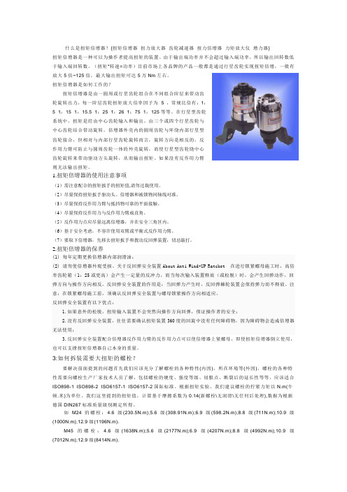
什么是扭矩倍增器?{扭矩倍增器扭力放大器齿轮减速器扭力倍增器力矩放大仪增力器}扭矩倍增器是一种可以为操作者提高扭矩的装置。
由于输出端功率并不会超过输入端功率,所以输出回转数低于输入端回转数。
(扭矩*转速=功率)目前市场上各品牌的产品一般都是通过行星齿轮实现扭矩倍增,一般有放大5倍~125倍,最大输出扭矩可达5万Nm左右。
扭矩倍增器是如何工作的?扭矩倍增器是由一圆周或行星齿轮组合在不同组合阶层来带动齿轮旋转出力,每一阶层齿轮扭矩放大倍率因子为 5 ,常规比倍有:1:5 1:15 1:15.5 1:25 1:26 1:75 1:125等等。
在行星型齿轮系统中,扭矩是经由中心齿轮输入和输出。
由三个或四个行星齿轮与中心齿轮结合带动旋转。
倍增器外壳内的圆周齿轮与环绕内部行星型齿轮接合,但相对与内部行星齿轮旋转而言,旋转方向是相反的。
反作用力臂可防止与圆周齿轮一体的外壳旋转,而使行星型齿轮绕中心齿轮旋转来带动驱动方头旋转,从而输出扭矩。
如果没有反作用力臂则无法输出扭矩。
1.扭矩倍增器的使用注意事项(1)需注意配合的扭矩扳手的扭矩值,请勿过载使用。
(2)尽量保持扭矩扳手驱动头、倍增器和被锁物同轴线对准。
(3)尽量保持反作用力臂与抵挡物可靠的平面接触。
(4)尽量保持反作用力与反作用力臂成直角。
(5)反作用力点应尽量远离倍增器,并在安全三角区内。
(6)基于安全考虑,不容许使用双臂或平衡式反作用力臂。
(7)要取下倍增器,先移去扭矩扳手和拨动反回弹装置,切忌敲打。
2.扭矩倍增器的保养(1) 每年定期更换倍增器内部润滑油;(2) 请勿使倍增器外观受损。
关于反回弹安全装置About Anti Wind-UP Ratchet 在进行锁紧螺母施工时,高倍率齿轮箱(1:25或更高)会产生一定量的反冲力,而当每次输入装置释放(或松脱)时,会产生回弹动作,回弹方向与操作方向相反。
反回弹安全装置的作用是:当回弹力产生时,反回弹棘轮装置会保持弹力而不释放。
倍增器的使用介绍

二:工厂设备展示
• 1.精密的加工设备
• • • 工厂拥有一流的 数控加工设备,主要 部件全部有美国进又
• 2.国际一流的扭力实验室
• • 扭力测试实验室严格依照欧洲标 准,确保产品精度优于国际标准
三:公司国内主要客户群体
• 1.上海龙工 • 2.中国三一重工 • 3.中国胜利油田 • 4.中国大连船厂 • 5.广州地铁集团 • 6.广汽集团 • 7.大亚湾核电 • 8.广西玉柴 • 9.山东潍柴 • 10.徐工集团 • 11.南昌动车组 12.美国ABB公司上海工厂 13.上海704动力研究所 14.一汽集团青岛工厂 15.江苏扬子集团 16.青岛海尔集团 17.天津空客集团 18.盐城起亚汽车工厂
四:公司展会以及国外客户参观
五:公司专利以及质量认证
六:扭力倍增器的使用介绍
• 1.产品图片
七:扭力倍增器的规格
八:扭力倍增器的功能图解
换向扭 输入方榫
反力臂
输出方榫
10.扭力倍增器使用注意事项
• • • • • • • • • • • 正确的使用方法可以让扭矩倍增器的使用寿命加长。首先,和上海朕诺机械设备有限公司小编一起来了解 扭矩倍增器的使用注意事项: (1)需注意配合的扭矩扳手的扭矩值,请勿过载使用。 (2)尽量保持扭矩扳手驱动头、倍增器和被锁物同轴线对准。 (3)尽量保持反作用力臂与抵档物可靠的平面接触。 (4)尽量保持反作用力与反作用力臂成直角。 (5)反作用力点应尽量远离倍增器,并在安全三角区内。 (6)基于安全考虑,不容许使用双臂或平衡式反作用力臂。 (7)要取下倍增器,先移去扭矩扳手和拨动反回弹装置,切忌敲打。 (8)如使用大型倍增器,请搭配吊车等工具配合使用。 正确的使用方法可以让扭矩倍增器的使用寿命加长,扭矩倍增器的保养也可以直接它的使用年限,下面就 来看看具体方法: (1)每年定期更换倍增器内部润滑油 (2)请勿使倍增器外观受损。
- 1、下载文档前请自行甄别文档内容的完整性,平台不提供额外的编辑、内容补充、找答案等附加服务。
- 2、"仅部分预览"的文档,不可在线预览部分如存在完整性等问题,可反馈申请退款(可完整预览的文档不适用该条件!)。
- 3、如文档侵犯您的权益,请联系客服反馈,我们会尽快为您处理(人工客服工作时间:9:00-18:30)。
扭矩倍增器
使用说明书
上海高致精密仪器有限公司
一、产品简介
工业行业以及相关产业行业生产检修安装现场,紧固和拆卸大直径螺栓螺母相当困难,尤其是操作人员在狭窄的施工环境中,这一问题显得更为突出。
本厂根据用户的实际需要,结合国内外先进技术,研制生产的新型扭矩倍增器,可以帮助您从根本上解决这一难题(组装方式如图,20型以上注意棘轮扳手和主机机芯上的力矩开关方向要同时通向)。
该产品主要组成部件为:短柄棘轮扳手、防弹锁、力矩倍增器、反力臂支爪(反作用脚),套简扳手组成(见图)。
其原理为:多级变速,力矩放大。
操作人员只需施加很小的力,即可以在很短的时间内得到5-100倍的输出力矩,从而轻便快捷地完成螺栓螺母的紧固或拆卸工作。
扭矩倍增器参考图
二、产品主要特点
1、适用于各种工作环境。
2、轻便灵巧、手工操作。
3、可调换不同规格的套筒,以适用多种大直径螺栓螺母。
4、最小的工具直径,最大的力矩输出。
5、设计系列化,产品采用硬质面镀,决不锈蚀。
四、技术参数及尺寸数据表
注:(1)三表是螺栓等级为8.8级做出,仅供参考。