声学工具箱手册
行李箱饰件设计手册
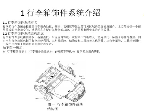
3 设计准则
3.3.4 行李箱对造型方案的要求和检查
2013-9-2 7
在前期的造型过程中,要对设计部的造型方案进行分析检查,尤其是零件间隙、制造可行性、安装可行性等, 并和设计人员及时沟通。其主要目的是: 1. 保证造型方案的可行性 2. 保证造型方案的工程方案可行性、质量及目标价格满足项目要求。
2013-9-2 12
3 设计准则
3.4.7 行李箱后盖拉手的要求
Global推荐使用SAAB9-3 12785350作为共用零件。
2013-9-2 13
3 设计准则
3.5行李箱饰件系统的设计技巧2013-9-2 14
3.5.1 衣帽架下饰板和绞链处的设计技巧
在有些高档车上会在行李箱区域布置衣帽架下饰板,又由于不同的后盖绞链结构,周边零件较多,配合较复杂, 对于这块区域尤其要引起注意。下面以SGM和一些竞争车型为例,说明一下设计技巧。 后盖绞链一般分为气弹簧四连杆式绞链和鹅颈式绞链。由于气弹簧四连杆式绞链布置在行李箱外,与行李箱饰 件没有配合关系,衣帽架下饰板和侧饰板配合较好,外观也较美观。在条件允许的情况下,推荐使用该种绞链 和行李箱饰件的配合,例如SGM 980车型就是采取了这种结构(如下图所示):
行李箱饰件与密封条开口需有10mm的搭接量。
2013-9-2 10
3 设计准则
3.4.5 行李箱地板饰件与车身钣金的配合要求
1、备胎盖板毯面与周边行李箱零件允许有7mm的间隙; 2、备胎盖板背面到备胎轴载重支撑面的定义的设计间隙为10.0mm; 3、后备箱饰件地板毯面与备胎盖板基材的搭接量为10.0mm; 4、备胎盖板每300mm就应该有支撑来满足承载性能要求; 5、备胎盖板基材周边必须与钣金的搭接量必须满足10mm
北极工具箱说明书

Distributed by:Northern Tool & Equipment Company, Inc.Burnsville, Minnesota 5-DRAWER ALUMINUM TOOL BOX INSTRUCTIONSMOUNTING INSTRUCTIONFor Customer Service or Warranty Information: 1-800-222-5831Truck BedNOTE:If your truck has a bed liner, use these instructionsas a guide only. Due to the many di erences in bed linerthickness and t, longer attaching devices are recommended.You will need to insure that your truck box is mounted securely to the truck, not the bed liner.5 Drawer Tool BoxSecure Bottom Tray to Truck BedOpen the front door and remove the bottom drawer to access the locking tab on the body oor. This tab will allow you to release the mounting tray from the tool.While pressing the 2 latch posts on the inside of the box together, pushthe bottom tray towards the back of the box. This will result in theseparation of the mounting tray from the main body housing, leaving 2 separate parts.Position the mounting tray behind the fender are of your choice, ensuring that the front faces the tailgate.When you have the mounting tray in the desired position, it is recom-mended to mark the holes prior to drilling, in case shifting of the mounting tray occurs during drilling.Using a 3/8” drill bit, drill through the bed exterior on your markings.Thoroughly clean the surface location where the tool box will be mounted, then line up the drill holes to the mounting tray.1.2.3.4.5.6.Using the bolts supplied, begin inserting them through the mounting tray into the drilled holes. Rotate all screws before tightening any screw completely. As the screws becometighter, completely fasten them to the frame.Ensure the undercarriage of the tool box is free of debris, as well as the mounting tray. Slide the tool box back onto the mounting tray in a similar fashion as it was removed.Re-insert any trays that were removed from the tool box during installation.Remove the keys from the interior of the box and store them in a safe location.7.8.9.10.Any leaking caused by unsealed holes in the box bottom will void the warranty.Read these instructions to familiarize yourself with assembly and installation. This tool box is designed for certain applications only.Northern Tool & Equipment is not responsible for issues arising from modi cation or improper use of this product such as an application for which it was not designed. We strongly recommend that this product not be modi ed and/or used for any application other than that for which it was designed.This tool box must be securely mounted to prevent movement or shifting.。
Waves11TRACT声场校准系统插件介绍和使用分享

WaVeSl I Z TRACT声场校准系统插件介绍和使用分享雪帝数字音频WaVeS技术顾问潘伟乐对TRACT声场校准插件的深度分享,强烈推荐! 以下文章来源于PanChO聊音响,作者PanChOPanChO聊音响专注于音频技术,专业设备,混音知识以及各类口家设备分享WAVES TRACT声场校准系统插件-介绍和使用2018年,fbxxxx上面突然发布了一个视频,在XX展那里WaVeS发布一个新的现场系统调试插件,不同于之前的X-FDBK和SUbAlign系统调试插件,不单单只是解决针对现场系统的某一个环节的问题。
比如反馈或者低音相位对齐。
而是可以绕过处理器来进行系统调试,关于系统调试作用性或者正确性就不展开讨论了。
我们先看看一个介绍视频了解一下TRACT的校准系统:TRACT简介以下应用WaVeS官网对于系统调试的介绍:”正如画家需要一幅干净的画布开始作画,混音师需要一个平衡良好的音响系统来进行混音。
由于每个音响系统都不一而同,并且在各种环境中表现各异,我们就需要校准系统以平整其性能:在现场设置中,这被称为PA调整。
如果不进行这种调节,系统的频率响应就会表现得异常:音乐听起来可能与我们习惯的不同,而且混音效果也不会达到我们的预期。
还有更糟糕的,如果一个系统的时间不对齐,则可能岀现相位抵消,给宝贵的低频冲击力带来致命影响。
"但是我们山于在许多情况下是使用第三方的设备,我们对系统处理器的调节都是受限的,并且在试音检查前的时间相当有限。
这时候TRACT插件可以很好帮忙我们解决频响和相位的问题并且解决时间也会大大缩短。
(请注意:因为TRACT 需要搭配Smarrt v8版本或者Smarrt di软件使用,不然就只是一个拥有8段IlR 均衡滤波器。
无法使用fir自动化eq。
)PS: TRACT的IIR滤波器包含有钟形滤波、低/高搁架滤波、平顶滤波(FIat-ToPS)、巴特沃斯(BUtterWOrth)和林奎茨-瑞利(LinkWitZ-Riley)曲线,以及具有可变频率枢轴点的倾斜均衡器(TiltEQ)和2阶全通滤波器。
声学工具箱

声学工具箱声学工具箱是一种用于声音分析和处理的工具集,旨在帮助使用者有效地研究、测量和改进声学环境。
声学工具箱包含了各种专业的软件和硬件设备,用于收集、分析和处理声音信号。
无论是声学工程师、音频专家还是声音爱好者,都可以从声学工具箱中受益。
声学工具箱的组成部分广泛,包括了以下几个方面的内容:1.声音测量设备:声学工具箱中的测量设备包括声音传感器、声音分析仪、噪声计等。
这些设备可以帮助用户对声音进行高精度的测量和分析,从而提供详尽的声学数据。
无论是在工业环境中进行噪声控制,还是在演出场所进行声音质量评估,这些设备都能帮助使用者全面了解声学环境和声音特性。
2.声音编辑软件:声音编辑软件是声学工具箱中的重要组成部分。
它们提供了一系列功能,用于对声音进行编辑、剪辑和处理。
使用者可以通过声音编辑软件对录音进行修剪、混合、添加音效等操作,从而实现对声音的精细控制和改进。
声音编辑软件通常包括了多个音轨,使得用户可以同时处理多个声音源,满足各种实际需求。
3.声学模拟工具:声学模拟工具是声学工具箱中的一类软件,用于模拟声音在特定环境中的传播和衰减过程。
这些工具可以帮助用户预测声音在不同环境中的声压级、反射、衍射等参数,从而指导声学设计和优化。
声学模拟工具常用于建筑、演播室、房间声学等领域的设计和研究。
4.声音分析工具:声音分析工具是声学工具箱中的重要组成部分,用于对声音信号进行详细的频谱、时域、频域等分析。
这些工具可以提取音频中的特征,如频谱特性、频率分布、音高、共振峰等信息。
声音分析工具可用于声乐、音乐、音频处理等领域的研究和实践。
5.声音效果器:声音效果器是声学工具箱中广泛使用的一种设备或软件,用于对声音进行实时处理和增强。
声音效果器可以通过添加混响、合唱、延迟、均衡器等效果,改变声音的音色、延音时间、音量等特性,从而实现声音的艺术加工和创造性处理。
综上所述,声学工具箱是一套专业的声音分析和处理工具集,涵盖了声音测量设备、声音编辑软件、声学模拟工具、声音分析工具和声音效果器等多个方面。
pro tools教程
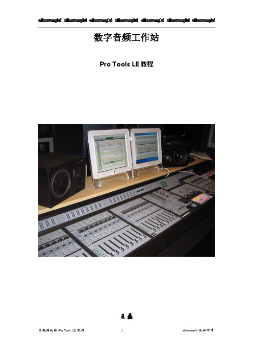
数字音频工作站Pro Tools LE教程王磊PRO TOOLS 初级教程说明:本教程只适用于刚刚接触或正要学习PRO TOOLS的同学使用。
今天要给同学说一下在数字音频工作站领域中,最为流行并享有盛誉的音频软件Pro Tools(当然PRO TOOLS的高端产品视频功能也很强大,但我们这里只说音频这方面)。
由Digidesign公司出品的Pro Tools一直是录音行业所推崇的音频处理系统,专业版的TDM系统一般有Pro Tools 24 MIX Plus;Pro Tools 24 MIX;Pro Tools 24等;以及刚刚推出的Pro Tools HD系统。
Pro Tools的软件至今也已升级到6.9的版本。
还有最近出的两个小玩意MBOX和DIGI002。
我们所说的DIGI001系统是这些中最简单的一个,就是由简化版的PRO TOOLS LE软件加上硬件DIGI001组成。
简化版的Pro Tools我们称它为Pro Tools LE,由于绝大多数人都拿不出几十万人民币来购置一套带有硬件DSP功能的Pro Tools 的专业级系统,因此在这里我们就以简化版的Pro Tools 来详细介绍一下,几乎具备TDM系统的大部分重要功能的软件Pro Tools LE与硬件DiGi 001的具体使用。
首先我们先来认识它们:第一节Digi 001这个就是它了,(当然图中少了一块PCI的插卡,因为我没搞到它的图)Digi 001主要由外置接线箱(AD/DA转换器)和PCI插卡组成,中间用电缆连接,是一套真正的“即插即用”系统。
先看前面,在它的前面板上有两个Neutrik复合式(卡侬或大三芯通用)的Mic/LINE前级放大器,有独立的增益控制(GAIN),带有-26db的固定哀减(PAD)按钮,是专门为输入线路信号时使用的。
此外这两个接口还配有48V幻相供电(PHANTOM POWER),可直接接入需48V的电容话筒进行工作。
Waves JJP Drums插件用户手册说明书

WAVES JJP DRUMS User GuideTABLE OF CONTENTSCHAPTER 1 – INTRODUCTION (3)1.1W ELCOME (3)1.2P RODUCT O VERVIEW (3)1.4A F EW W ORDS FROM JJP (4)CHAPTER 2 – QUICKSTART GUIDE (5)CHAPTER 3 – CONTROLS, CONCEPTS, AND TERMINOLOGY (6)Chapter 1 – Introduction1.1 WelcomeThank you for choosing Waves! In order to get the most out of your new Waves plugin, please take a moment to read this user guide.To install software and manage your licenses, you need to have a free Waves account. Sign up at . With a Waves account you can keep track of your products, renew your Waves Update Plan, participate in bonus programs, and keep up to date with important information.We suggest that you become familiar with the Waves Support pages:/support. There are technical articles about installation, troubleshooting, specifications, and more. Plus, you’ll find company contact information and Waves Support news.1.2 Product OverviewThe Waves Signature Series is our exclusive line of application-specific audio processors, created in collaboration with the world’s top producers, engineers, and mixing engineers. Every Signature Series plug-in has been precision-crafted to capture the artist’s distinct sound and production style. For experienced and aspiring audio professionals alike, the Waves Signature Series allows you to dial up the sound you’re looking for quickly, without interrupting the creative flow.The JJP Collection consists of 6 plug-ins, each designed to handle a specific mixing task.•JJP Vocals•JJP Drums•JJP Bass•JJP Guitars•JJP Cymbals & Percussion•JJP Strings & Keys1.3 ComponentsWaveShell technology enables us to split Waves processors into smaller plug-ins, which we call components. Having a choice of components for a particular processor gives you the flexibility to choose the configuration best suited to your material.The Waves JJP Drums has several components:•JJP Drums Mono – Mono in to Mono out component•JJP Drums m>s – Mono in to Stereo out component•JJP Drums Stereo – Stereo in to Stereo out componentPlease note: In order to maximize performance while optimizing the correct processing for different applications, we split the drums into two separate plug-ins:•JJP Drums for kicks, snares, and toms•JJP Cymbals & Percussion, for hi-hats, overheads, room, and loops1.4 A Few Words from JJP"There are certain things you usually just take for granted when you’re mixing drums. Sure, the snare has to snap. Or maybe you want it to have a woodier sound. The bass drum has to have a nice bottom. But beyond that, there’s a whole other range of things you need to consider to really make the song come alive. Maybe there’s some tonality in the drum kit that you want to emphasize. How do the drums relate to the rest of the song? And once you figure all that out—how do you get there? Well, what’s really great is, JJP Drums is a plug-in that can do it all."Chapter 2 – Quickstart Guide•Insert the JJP Drums plug-in on the track you wish to process.•Choose the Drum Type:KICK IN – For main kick/bass drum tracks.KICK OUT– If your kick was recorded using two microphones, use for themic positioned further away from the drum.SNR TOP – For main snare track. If your snare was recorded using twomicrophones, use this to process the top mic.SNR BOT – If your snare was recorded using two microphones, use thisto process the bottom mic.TOMS – For both mounted and floor toms.•Adjust the Sensitivity control until you achieve proper (yellow) levels, as indicated by the Sensitivity LED.•Adjust the various Main Section controls located below the Sensitivity knob to shape your sound.•Use the Center Section faders to adjust the sonic color.•If the Clip LED lights up repeatedly or stays lit, lower the Output level fader accordingly.JJP has optimized the default settings for each Type. These settings may or may not require additional adjustment once optimal Sensitivity has been achieved.Chapter 3 – Controls, Concepts, and TerminologyTypesThe JJP Drums plug-in includes five Types to address a range of source materials: Kick In, Kick Out, Snr Top, Snr Bot, and Toms.Sensitivity SectionThe Sensitivity LED’s 3 colors indicate when appropriate levels are reached:o LED Off (too low)o Green (good)o Yellow (optimal)o Red (very hot)Turn the Sensitivity Control until the LED lights up. For best results, use the section of your track with the highest peaks.In most cases, the Sensitivity LED indicates that your levels hit the processor in a way that will give you the intended output result. However, it’s important to keep in mind that optimal results for your source material may be achieved even when the Sensitivity LED does not display “optimal” levels (yellow). As always, trust your ears.Main SectionThe Main Section gives you control over basic dynamics & EQ. All processing is influenced by this section. The JJP Drums plug-in also includes a Phase reversal switch.Please note: Since the EQ ranges of certain drums differ from the default settings, they are labeled “Low 2” and “High 2” for automation purposes.Main FaderThe Main Fader controls the Main Section direct level.Center Section FadersThe Center Section faders represent auxiliary returns with additional processing, sent from the main fader pre-fader. Above each fader, there is a dedicated mute button.It may help to think of each plug-in as a mini-mixing console.Please note: Certain faders may change, depending on the selected Type. This is intentional, and represents the actual processing JJP uses for that source or instrument.Master FaderThe Master fader controls the master output signal level.Meter SectionThe Meter switch toggles meter monitoring between input and output modes. The Clip LED lights up when levels reach 0 dBFS; click to reset.Signal FlowWaveSystem ToolbarUse the bar at the top of the plugin to save and load presets, compare settings, undo and redo steps, and resize the plugin. To learn more, click the icon at the upper-right corner of the window and open the WaveSystem Guide.。
扩声系统安装调试
扩声系统调试 本文档提供如何使用NTi Audio 设备进行扩声系统和疏散逃生系统的调试和服务。
您需要:Exel 声学套件• XL2 分析仪• M4260 量测麦克风• MR-PRO 信号发生器• ASD 缆线• 缆线测试插头• 主电源适配器• 系统工具箱TalkBox 声学信号发生器您可以:NTi Audio 仪器可用于下列测试:• 缆线测试• 测量 THD+N • 100V 阻抗测试 • 极性测试• RTA 实时频谱分析• 扬声器延迟设置• 噪声曲线• 混响时间 RT60• 语言清晰度 STIPA扩声系统安装声学套件TalkBox 声学信号发生器怎样测试缆线可以查出平衡XLR 线的任何缺陷,即便缆线已经被装到天花板,墙壁或地板内。
将缆线测试适配器连接到缆线的公头将MR-PRO信号发生器连接到缆线母头在MR-PRO 上,从菜单中选择CABLETEST 缆线测试会有醒目的提示信息显示缆线是否完好检测到断开线路缆线中两条线路连接错误,如PIN 1 和 PIN 2查错提示,请看 附录 A怎样测量THD+N您系统中的某个组件可能会在信号通道中增加非预期的谐波,失真或噪声,也可能该组件没有正确安装或接地,增益过小或过大,又或者组件损坏或有质量问题。
您都可以用XL2 的THD+N功能测量总谐波失真和噪声。
将XL2 连接到系统输出端将MR-PRO 连接到系统输入端在M R-PRO 上,从主菜单选择GENERATOR 信号发生功能,选择WAV 中的SINE 正弦信号,将电平设置为0.00dBu,频率设置为1.000kHz。
在XL2 上,从主菜单选择RMS/THD+N 功能,选择零计权滤波器(测量所有频点的平坦响应),设置LVLRMS单位为dBu,THDN单位为%.显示输入信号是否平衡。
LVLRMS 值显示原始信号的增益或损失:0.0dBu 表示没有增益会损耗。
FREQ 值显示XL2 探测到的频率。
如1.00000 kHz.THDN 值是一个比率,表示XL2 收到的信号中有多少不是来自这1kHz 的正弦信号。
基于Kriging替代模型的水声传播损失不确定性量化研究
基于Kriging替代模型的水声传播损失不确定性量化研究ZHANG Lilun;GUO Xianpeng;WANG Dezhi;WANG Yongxian;WU Yanqun【摘要】针对传统水声传播模型在计算精度与效率上难以平衡的问题,本文提出了一种利用Kriging替代模型进行水声传播损失不确定性量化的快速计算方法.利用Kriging模型替代经典Kraken传播模型,缓解Kraken模型耗时的问题,以较高的效率和精度进行水声传播计算并得到相应的水声传播损失.在此基础上,进一步将Kriging替代模型与蒙特卡洛方法结合起来,对由多个环境变量引起的水声传播损失进行不确定性分析,得到传播损失的后验概率密度分布以及90%置信区间分布.试验结果表明所提方法可以快速有效量化水声传播损失的不确定性,为水声传播损失不确定性量化提供了一种新的思路和方法.【期刊名称】《哈尔滨工程大学学报》【年(卷),期】2019(040)001【总页数】6页(P88-93)【关键词】Kriging替代模型;Kraken水声模型;蒙特卡洛方法;水声传播损失;不确定性量化【作者】ZHANG Lilun;GUO Xianpeng;WANG Dezhi;WANG Yongxian;WU Yanqun【作者单位】【正文语种】中文【中图分类】O427.1海洋是一个时变、空变的声传输系统,海洋环境的复杂性会显著影响水声传播计算的准确性。
通常海洋声学环境是未知的,并且充满不确定性,声场预报受到海洋环境不确定性效应的显著影响。
声场预报中,水声传播损失的准确预报对于准确解算声呐方程,得到声呐作用距离和预测声呐性能起到关键作用。
Gerstoft 等[1]利用极大似然估计的方法尝试量化由海洋环境不确定性所导致的水声传播损失,得到水声传播损失在距离和深度两个方向上的全概率分布。
Huang 等[2]进一步提出采用马尔科夫链蒙特卡洛方法利用抽样的样本将环境参数的不确定性传递给水声传播损失的计算过程,利用统计学中置信区间和相关系数对传播损失的不确定性进行量化和表征。
WAVES效果器说明书四篇
WAVES效果器说明书四篇篇一:WAVE效果器REVERB的中文说明书第一章- 简介感谢使用Waves Renaissance Reverberator软件。
这个软件是为使用支持DIRECT X专业音频软件的用户设计的。
Renaissance Reverb 软件可以对传统的声音进行极好的控制。
现在市场上有很多处理器用于直接模仿老式乐器的声音。
但是Renaissance Reverb 软件则为用户提供了一个可以创新及灵活应用的、用于模仿老式合成器声音的工具。
我们采用了TrueVerb软件中早期反射声系统作为开始,然后以多种方式对其进行改造,建立一个新的后期混响。
我们同时还建立了一个可视性很强的界面,用于监视反馈信号及调整各项参数。
第二章 - 快速入门基本操作方法对于干湿对比度基本的使用手法是:• 在使用断点插入为一个音轨提供效果时,在调入一个预置方案后,应将湿/干对比度设置成100%。
• 在使用辅助总线为一个音轨提供效果时,在调入一个预置方案后,应将湿/干对比度设置成50%。
使用这个软件的大体过程如下:• 调用一个预置方案。
• 调整用于修饰声音色彩的混响特性。
• 调整混响电平(同早期反射声的比例也随之变化)。
• 调整各均衡参数,对某一频段进行提升或衰减。
• 对各项参数做细微的调整。
在操作界面的最上端,是Waves系列标准的控制模式。
详见“WaveSystem”一章。
该章所涉及的内容在使用所有Waves系列的软件时都会遇到,了解这些控制按钮会为你的操作带来很多方便。
Waves系列软件性能非常出色,它们可以使用户同时控制多个参数。
界面上方的三块图形显示了时间和频率反应特性。
在混响阻尼(Reverb Damping)和混响均衡(Reverb EQ)图形上,只需要简单地拖动图形上的节点,就可以改变混响的阻尼和均衡参数。
在界面的下方有9个推子,这9个推子可分为两类:控制声音的特性和控制音量。
第三章 - 软件的构成使用软件时,用户可以在音频软件的有关编辑菜单中找到plug-in (插件)菜单,然后就可以找到Waves 系列的插件程序。
迪伯音频工具箱 D20 插头微调器说明书
(See Troubleshooting Tips On Back)4.24C Quick Reference GuideInput . . . . . . . . . . . . . . . . . . . . . . .Active Balanced, 18K ΩMax. Input Level . . . . . . . . . . . . .+20dBuInput Gain Range . . . . . . . . . . . .-40dB to +12dB Output . . . . . . . . . . . . . . . . . . . . .Active Balanced, 112ΩMax. Output Level . . . . . . . . . . .+20dBuOutput Gain Range . . . . . . . . . .-40dB to +12dBEQEQ Filter Types . . . . . . . . . . . . .1st or 2nd Order High or Low Shelf, Parametric Shelving Filter Gain Range . . . .±15dBShelving Filter Freq. Range . . .Low Shelf 19.7Hz to 2kHz, High - 3.8kHz to 21.9kHzParametric Filter Gain Range . .+15dB/-30dBParametric Filter Freq. Range .19.7Hz to 21.9kHz, 1/24 Octave Steps Parametric Filter Bandwidth . .Four Octaves to 1/64 OctaveInput Delay . . . . . . . . . . . . . . . . .0-682 milliseconds Output Delay . . . . . . . . . . . . . . . .0-21.3 milliseconds CrossoverHPF and LPF Frequency Range 19.7Hz to 21.9kHz, OffAvailable Filter Types . . . . . . . .12dB/Oct Butterworth, 12dB/Oct Bessel, 12dB/Oct Linkwitz-Riley 18dB/Oct Bessel, 18dB/Oct Linkwitz-Riley24dB/Oct Butterworth, 24dB/Oct Bessel, 24dB/Oct Linkwitz-Riley 48dB/Oct Butterworth, 48dB/Oct Bessel,48dB/Oct Linkwitz-RileyLimiterThreshold Range . . . . . . . . . . . .-20dBu to +20 dBu Ratio Range . . . . . . . . . . . . . . . .1.2:1 to INF:1Attack Time Range . . . . . . . . . .0.5ms to 50ms Release Time Range . . . . . . . . .10ms to 1 SecondPropogation Delay . . . . . . . . . . .1.46msMax RS232 Cable Distance . . .Up to 1300 ft (using high qualtiy cable)Max MIDI Cable Distance . . . . .Up to 500 ft (using high quality cable)AC Requirements . . . . . . . . . . . .Universal Power Supply, 80-260VAC, 50/60Hz(See Troubleshooting Tips On Back)4.24C Quick Reference GuideInput . . . . . . . . . . . . . . . . . . . . . . .Active Balanced, 18K ΩMax. Input Level . . . . . . . . . . . . .+20dBuInput Gain Range . . . . . . . . . . . .-40dB to +12dB Output . . . . . . . . . . . . . . . . . . . . .Active Balanced, 112ΩMax. Output Level . . . . . . . . . . .+20dBuOutput Gain Range . . . . . . . . . .-40dB to +12dBEQEQ Filter Types . . . . . . . . . . . . .1st or 2nd Order High or Low Shelf, Parametric Shelving Filter Gain Range . . . .±15dBShelving Filter Freq. Range . . .Low Shelf 19.7Hz to 2kHz, High - 3.8kHz to 21.9kHzParametric Filter Gain Range . .+15dB/-30dBParametric Filter Freq. Range .19.7Hz to 21.9kHz, 1/24 Octave Steps Parametric Filter Bandwidth . .Four Octaves to 1/64 OctaveInput Delay . . . . . . . . . . . . . . . . .0-682 milliseconds Output Delay . . . . . . . . . . . . . . . .0-21.3 milliseconds CrossoverHPF and LPF Frequency Range 19.7Hz to 21.9kHz, OffAvailable Filter Types . . . . . . . .12dB/Oct Butterworth, 12dB/Oct Bessel, 12dB/Oct Linkwitz-Riley 18dB/Oct Bessel, 18dB/Oct Linkwitz-Riley24dB/Oct Butterworth, 24dB/Oct Bessel, 24dB/Oct Linkwitz-Riley 48dB/Oct Butterworth, 48dB/Oct Bessel,48dB/Oct Linkwitz-RileyLimiterThreshold Range . . . . . . . . . . . .-20dBu to +20 dBu Ratio Range . . . . . . . . . . . . . . . .1.2:1 to INF:1Attack Time Range . . . . . . . . . .0.5ms to 50ms Release Time Range . . . . . . . . .10ms to 1 SecondPropogation Delay . . . . . . . . . . .1.46msMax RS232 Cable Distance . . .Up to 1300 ft (using high qualtiy cable)Max MIDI Cable Distance . . . . .Up to 500 ft (using high quality cable)AC Requirements . . . . . . . . . . . .Universal Power Supply, 80-260VAC, 50/60HzR2R24.24C TROUBLESHOOTING TIPS7.1 - Audio Troubleshooting TipsNo power - Is the detachable AC cord fully plugged in? Is the rear panel power switch on?Controls don't work - check the Security Level. If set to Full Lockout, then Protea unit is "view only". Change security settings in Util menu.No sound - Check to see if the input or output is muted. Is the input or output Gain turned down? Check the selected audio source(s) for each output, making sure there is signal applied to the designated input(s). If the crossover is used, make sure the high pass filter (HPF) is set to a lower frequency than the low pass filter (LPF).Clip light stays on - Is the input signal level too high? Check to see that the nominal input level is 0dBu, allowing 20dB of input headroom. Are input or output gain settings too high? Check to see if an EQ filter has too much boost.Distorted sound but no Clip LED- Check individual EQ filters to see if there is excessive boost.Muffled sound - If expecting full range audio on an output, make sure the crossover settings are not inadvertently set so as to limit the pass band.Excessive Noise - An input signal level or an input gain setting that is too low could require the loss to be made up for at the output gain stage, producing more noise than a properly set up gain structure. Do not use the 4.24C for dramatic increases in level, but rather optimize the signal source for a nominal 0dBu output.Forgot the password - See section 4.7e of Manual7.2 RS-232/MIDI Troubleshooting Tips1. Test all data cables. Use standard MIDI cables and RS232 data cables with all conductors wired straight through. Monitor cables and Null Modem cables use non-standard wiring schemes, they will not work with a Protea. See section 5.2 and 5.3 if using custom wiring.2. Use a valid PC serial port. You must use a serial port that is not opened to any other application, such as a mouse, modem, or another program. To verify that the port exists look in: Control Panel - System - Device Manager - Ports. While you're there, make sure that the port has no warnings or conflicts. There is no need to change the port settings because Protea System Software will do this automatically. Finally, you must select the valid port in Protea System Software. This is done under the Communi-cations heading - Com Port Assignment.3. Make sure that the RS-232 mode switch, located on the back of4.24C, is in the "out" position. There is just one exception to this rule: the RS-232 mode switch gets pushed in only when both the RS232 Dataport is connected to a PC, and the 4.24C is part of several Protea products in a MIDI chain.4. Make sure the MIDI channel selected within the 4.24C (Util menu) matches the MIDI channel chosen for the crossover section of Protea System Software, and make sure that no other devices use that MIDI channel.4.24C TROUBLESHOOTING TIPS7.1 - Audio Troubleshooting TipsNo power - Is the detachable AC cord fully plugged in? Is the rear panel power switch on?Controls don't work - check the Security Level. If set to Full Lockout, then Protea unit is "view only". Change security settings in Util menu.No sound - Check to see if the input or output is muted. Is the input or output Gain turned down? Check the selected audio source(s) for each output, making sure there is signal applied to the designated input(s). If the crossover is used, make sure the high pass filter (HPF) is set to a lower frequency than the low pass filter (LPF).Clip light stays on - Is the input signal level too high? Check to see that the nominal input level is 0dBu, allowing 20dB of input headroom. Are input or output gain settings too high? Check to see if an EQ filter has too much boost.Distorted sound but no Clip LED- Check individual EQ filters to see if there is excessive boost.Muffled sound - If expecting full range audio on an output, make sure the crossover settings are not inadvertently set so as to limit the pass band.Excessive Noise - An input signal level or an input gain setting that is too low could require the loss to be made up for at the output gain stage, producing more noise than a properly set up gain structure. Do not use the 4.24C for dramatic increases in level, but rather optimize the signal source for a nominal 0dBu output.Forgot the password - See section 4.7e of Manual7.2 RS-232/MIDI Troubleshooting Tips1. Test all data cables. Use standard MIDI cables and RS232 data cables with all conductors wired straight through. Monitor cables and Null Modem cables use non-standard wiring schemes, they will not work with a Protea. See section 5.2 and 5.3 if using custom wiring.2. Use a valid PC serial port. You must use a serial port that is not opened to any other application, such as a mouse, modem, or another program. To verify that the port exists look in: Control Panel - System - Device Manager - Ports. While you're there, make sure that the port has no warnings or conflicts. There is no need to change the port settings because Protea System Software will do this automatically. Finally, you must select the valid port in Protea System Software. This is done under the Communi-cations heading - Com Port Assignment.3. Make sure that the RS-232 mode switch, located on the back of4.24C, is in the "out" position. There is just one exception to this rule: the RS-232 mode switch gets pushed in only when both the RS232 Dataport is connected to a PC, and the 4.24C is part of several Protea products in a MIDI chain.4. Make sure the MIDI channel selected within the 4.24C (Util menu) matches the MIDI channel chosen for the crossover section of Protea System Software, and make sure that no other devices use that MIDI channel.。
- 1、下载文档前请自行甄别文档内容的完整性,平台不提供额外的编辑、内容补充、找答案等附加服务。
- 2、"仅部分预览"的文档,不可在线预览部分如存在完整性等问题,可反馈申请退款(可完整预览的文档不适用该条件!)。
- 3、如文档侵犯您的权益,请联系客服反馈,我们会尽快为您处理(人工客服工作时间:9:00-18:30)。
声学工具箱手册
声学工具箱是声学领域中常用的一系列工具和软件包的集合,用于声学信号处理、声波分析、噪声控制等应用。
本手册旨在为声学工程师、研究人员和学生提供一个简明扼要的参考,介绍声学工具箱中的一些核心工具和其基本应用。
1. FFT(快速傅里叶变换)
FFT是一种重要的信号处理技术,用于将连续的时间域信号转换为频域信号。
在声学领域,FFT常被用于谱分析、信号滤波、频谱平坦化等应用。
常见的FFT
库包括Matlab中的fft函数和Python中的numpy.fft模块。
使用FFT进行频谱分析的基本步骤如下:
1.从声音信号中选择一个时间窗口。
2.对时间窗口应用窗函数以减少频谱泄漏。
3.进行FFT变换,将信号从时间域转换到频域。
4.绘制频谱图,分析声音信号的频谱特征。
2. FIR滤波器设计
FIR(有限脉冲响应)滤波器常被用于音频均衡、噪声消除和音频效果处理等
应用。
FIR滤波器的设计涉及到选择滤波器类型、滤波器阶数和滤波器系数等参数。
FIR滤波器设计的基本步骤如下:
1.确定滤波器的频率响应要求。
2.选择一个适当的FIR滤波器类型,如低通滤波器、高通滤波器或带
通滤波器。
3.确定滤波器的阶数,即滤波器中的延迟长度。
4.根据滤波器的类型和阶数,计算滤波器的系数。
5.将滤波器系数应用于信号,进行滤波处理。
3. 噪声分析与控制
噪声是声学领域中一个重要的研究方向,噪声分析与控制工具在许多应用中起
着至关重要的作用。
通过使用噪声分析与控制工具,可以评估环境噪声、噪声源的特性,并设计出有效的噪声控制措施。
常见的噪声分析与控制工具包括:
•噪声频谱分析仪:用于测量噪声信号的频谱分布和频谱特性。
•噪声源定位系统:用于定位噪声源的位置,并分析其空间分布特征。
•噪声控制器:用于设计和优化噪声控制算法,实现噪声主动控制和消除。
4. 音频模拟和数字化
音频模拟与数字化的过程涉及到声音信号的采样、量化和编码。
在声学工程中,音频模拟和数字化常用于音频信号的存储、传输和处理。
常见的音频模拟和数字化工具包括:
•音频采集设备:用于采集模拟声音信号,并将其转换为数字信号。
•音频编解码器:用于将数字音频信号转换为可存储、传输和处理的格式,如MP3、WAV等。
•音频编辑软件:用于音频信号的剪辑、混音、均衡等后期处理。
5. 声学建模与仿真
声学建模与仿真工具常用于声学场景的模拟和预测。
通过建立合适的声学模型,并使用仿真工具进行计算,可以预测声学场景中的声音传播、反射和吸收等现象。
常见的声学建模与仿真工具包括:
•有限元分析软件:将声学场景分解为有限个小区域,通过求解声学方程模拟声传播。
•射线追踪软件:通过追踪声线的路径和反射,预测声音在复杂场景中的传播。
•声学模拟器:用于模拟特定声学环境中的各种声音,如音乐厅、车辆内部等。
以上介绍了声学工具箱中的一些核心工具和其基本应用。
这些工具可以帮助声
学工程师和研究人员进行声学信号处理、噪声控制、声学建模等任务。
熟练掌握这些工具的使用方法和原理,对于声学领域的研究和应用具有重要意义。
希望本手册能为读者提供一个简明扼要的参考,以便更好地应用声学工具箱进行科研和工程实践。