磁共振无线充电鼻祖级论文-通过强耦合磁共振进行无线电力传输
基于磁耦合共振的能量无线传输性能分析

2 . e S c h o o l fA o u t o ma t i o n , £ n U n i v e  ̄ i t y f o T e c h n o l o g y ,Wu h a n H u b e i 4 3 0 0 7 2 , C h i n a )
磁共振(磁谐振耦合)无线充电技术鼻祖级文章-英文原文

Wireless Power Transfer via Strongly Coupled Magnetic ResonancesAndré Kurs,1* Aristeidis Karalis,2 Robert Moffatt,1 J. D. Joannopoulos,1 Peter Fisher,3Marin Soljačić11Department of Physics, Massachusetts Institute of Technology, Cambridge, MA 02139, USA. 2Department of Electrical Engineering and Computer Science, Massachusetts Institute of Technology, Cambridge, MA 02139, USA. 3Department of Physics and Laboratory for Nuclear Science, Massachusetts Institute of Technology, Cambridge, MA 02139, USA.*To whom correspondence should be addressed. E-mail: akurs@Using self-resonant coils in a strongly coupled regime, we experimentally demonstrate efficient non-radiative power transfer over distances of up to eight times the radius of the coils. We demonstrate the ability to transfer 60W with approximately 40% efficiency over distances in excess of two meters. We present a quantitative model describing the power transfer which matches the experimental results to within 5%. We discuss practical applicability and suggest directions for further studies. At first glance, such power transfer is reminiscent of the usual magnetic induction (10); however, note that the usual non- resonant induction is very inefficient for mid-range applications.Overview of the formalism. Efficient mid-range power transfer occurs in particular regions of the parameter space describing resonant objects strongly coupled to one another. Using coupled-mode theory to describe this physical system (11), we obtain the following set of linear equationsIn the early 20th century, before the electrical-wire grid, Nikola Tesla (1) devoted much effort towards schemes to a&m(t)=(iωm-Γm)a m(t)+∑iκmn a n(t)+F m(t)n≠m(1)transport power wirelessly. However, typical embodiments (e.g. Tesla coils) involved undesirably large electric fields. During the past decade, society has witnessed a dramatic surge of use of autonomous electronic devices (laptops, cell- phones, robots, PDAs, etc.) As a consequence, interest in wireless power has re-emerged (2–4). Radiative transfer (5), while perfectly suitable for transferring information, poses a number of difficulties for power transfer applications: the efficiency of power transfer is very low if the radiation is omnidirectional, and requires an uninterrupted line of sight and sophisticated tracking mechanisms if radiation is unidirectional. A recent theoretical paper (6) presented a detailed analysis of the feasibility of using resonant objects coupled through the tails of their non-radiative fields for mid- range energy transfer (7). Intuitively, two resonant objects of the same resonant frequency tend to exchange energy efficiently, while interacting weakly with extraneous off- resonant objects. In systems of coupled resonances (e.g. acoustic, electro-magnetic, magnetic, nuclear, etc.), there is often a general “strongly coupled” regime of operation (8). If one can operate in that regime in a given system, the energy transfer is expected to be very efficient. Mid-range power transfer implemented this way can be nearly omnidirectional and efficient, irrespective of the geometry of the surrounding space, and with low interference and losses into environmental objects (6).Considerations above apply irrespective of the physical nature of the resonances. In the current work, we focus on one particular physical embodiment: magnetic resonances (9). Magnetic resonances are particularly suitable for everyday applications because most of the common materials do not interact with magnetic fields, so interactions with environmental objects are suppressed even further. We were able to identify the strongly coupled regime in the system of two coupled magnetic resonances, by exploring non-radiative (near-field) magnetic resonant induction at MHzfrequencies. where the indices denote the different resonant objects. The variables a m(t) are defined so that the energy contained in object m is |a m(t)|2, ωm is the resonant frequency of thatisolated object, and Γm is its intrinsic decay rate (e.g. due to absorption and radiated losses), so that in this framework anuncoupled and undriven oscillator with parameters ω0 and Γ0 would evolve in time as exp(iω0t –Γ0t). The κmn= κnm are coupling coefficients between the resonant objects indicated by the subscripts, and F m(t) are driving terms.We limit the treatment to the case of two objects, denoted by source and device, such that the source (identified by the subscript S) is driven externally at a constant frequency, and the two objects have a coupling coefficient κ. Work is extracted from the device (subscript D) by means of a load (subscript W) which acts as a circuit resistance connected to the device, and has the effect of contributing an additional term ΓW to the unloaded device object's decay rate ΓD. The overall decay rate at the device is therefore Γ'D= ΓD+ ΓW. The work extracted is determined by the power dissipated in the load, i.e. 2ΓW|a D(t)|2. Maximizing the efficiency η of the transfer with respect to the loading ΓW, given Eq. 1, is equivalent to solving an impedance matching problem. One finds that the scheme works best when the source and the device are resonant, in which case the efficiency isThe efficiency is maximized when ΓW/ΓD= (1 + κ2/ΓSΓD)1/2. It is easy to show that the key to efficient energy transfer is to have κ2/ΓSΓD> 1. This is commonly referred to as the strongcoupling regime. Resonance plays an essential role in thisDS S D'' power transfer mechanism, as the efficiency is improved by approximately ω2/ΓD 2 (~106 for typical parameters) compared to the case of inductively coupled non-resonant objects. Theoretical model for self-resonant coils. Ourexperimental realization of the scheme consists of two self- resonant coils, one of which (the source coil) is coupled inductively to an oscillating circuit, while the other (the device coil) is coupled inductively to a resistive load (12) (Fig. 1). Self-resonant coils rely on the interplay between distributed inductance and distributed capacitance to achieve resonance. The coils are made of an electrically conducting wire of total length l and cross-sectional radius a wound into Given this relation and the equation of continuity, one finds that the resonant frequency is f 0 = 1/2π[(LC )1/2]. We can now treat this coil as a standard oscillator in coupled-mode theory by defining a (t ) = [(L /2)1/2]I 0(t ).We can estimate the power dissipated by noting that the sinusoidal profile of the current distribution implies that the spatial average of the peak current-squared is |I 0|2/2. For a coil with n turns and made of a material with conductivity σ, we modify the standard formulas for ohmic (R o ) and radiation (R r ) µ0ω l a helix of n turns, radius r , and height h . To the best of our knowledge, there is no exact solution for a finite helix in the literature, and even in the case of infinitely long coils, the solutions rely on assumptions that are inadequate for our R o = 2σ 4πa µ πωr 42 ωh 2 (6)system (13). We have found, however, that the simple quasi- R =0 n 2 + (7)static model described below is in good agreementr ε 12 c3π3 c(approximately 5%) with experiment.We start by observing that the current has to be zero at the ends of the coil, and make the educated guess that the resonant modes of the coil are well approximated bysinusoidal current profiles along the length of the conducting wire. We are interested in the lowest mode, so if we denote by s the parameterization coordinate along the length of the conductor, such that it runs from -l /2 to +l /2, then the time- dependent current profile has the form I 0 cos(πs /l ) exp(i ωt ). It follows from the continuity equation for charge that the linear charge density profile is of the form λ0 sin(πs /l ) exp(i ωt ), so the two halves of the coil (when sliced perpendicularly to its axis) contain charges equal in magnitude q 0 = λ0l /π but opposite in sign.As the coil is resonant, the current and charge density profiles are π/2 out of phase from each other, meaning that the real part of one is maximum when the real part of the other is zero. Equivalently, the energy contained in the coil is 0The first term in Eq. 7 is a magnetic dipole radiation term(assuming r << 2πc /ω); the second term is due to the electric dipole of the coil, and is smaller than the first term for our experimental parameters. The coupled-mode theory decay constant for the coil is therefore Γ = (R o + R r )/2L , and its quality factor is Q = ω/2Γ.We find the coupling coefficient κDS by looking at the power transferred from the source to the device coil,assuming a steady-state solution in which currents and charge densities vary in time as exp(i ωt ).P =⎰d rE (r )⋅J (r ) =-⎰d r (A&S (r )+∇φS (r ))⋅J D (r ) at certain points in time completely due to the current, and at other points, completely due to the charge. Usingelectromagnetic theory, we can define an effective inductance L and an effective capacitance C for each coil as follows:=-1⎰⎰d r d r ' µJ &S(r ')+ρS(r ') 4π |r -r |ε0≡-i ωMI S I Dr '-r|r '-r |3⋅J D (r )(8)L =µ04π |I 0 |⎰⎰d r d r 'J (r )⋅J (r ')|r -r '|where the subscript S indicates that the electric field is due to the source. We then conclude from standard coupled-mode theory arguments that κDS = κSD = κ = ωM /2[(L S L D )1/2]. When 1 1 ρ(r )ρ(r ') the distance D between the centers of the coils is much larger= C 4πε 0 |q 0 | ⎰⎰d r d r ' |r -r '|(4)than their characteristic size, κ scales with the D -3dependence characteristic of dipole-dipole coupling. Both κ and Γ are functions of the frequency, and κ/Γ and the where the spatial current J (r ) and charge density ρ(r ) are obtained respectively from the current and charge densities along the isolated coil, in conjunction with the geometry of the object. As defined, L and C have the property that the efficiency are maximized for a particular value of f , which is in the range 1-50MHz for typical parameters of interest. Thus, picking an appropriate frequency for a given coil size, as we do in this experimental demonstration, plays a major role in optimizing the power transfer.1 2Comparison with experimentallydeterminedU =2 L |I 0 |parameters. The parameters for the two identical helical coils built for the experimental validation of the power 1 2 transfer scheme are h = 20cm, a = 3mm, r = 30 cm, and n = =2C|q 0 | (5)5.25. Both coils are made of copper. The spacing between loops of the helix is not uniform, and we encapsulate theuncertainty about their uniformity by attributing a 10% (2cm) uncertainty to h . The expected resonant frequency given these22dimensions is f0 = 10.56 ± 0.3MHz, which is about 5% off from the measured resonance at 9.90MHz.The theoretical Q for the loops is estimated to be approximately 2500 (assuming σ = 5.9 × 10⁷ m/Ω) but the measured value is Q = 950±50. We believe the discrepancy is mostly due to the effect of the layer of poorly conductingcopper oxide on the surface of the copper wire, to which the current is confined by the short skin depth (~20μm) at this frequency. We therefore use the experimentally observed Q and ΓS= ΓD= Γ = ω/2Q derived from it in all subsequent computations.We find the coupling coefficient κ experimentally by placing the two self-resonant coils (fine-tuned, by slightly adjusting h, to the same resonant frequency when isolated) a distance D apart and measuring the splitting in the frequencies of the two resonant modes. According to coupled-mode theory, this splitting should be ∆ω = 2[(κ2-Γ2)1/2]. In the present work, we focus on the case where the two coils are aligned coaxially (Fig. 2), although similar results are obtained for other orientations (figs. S1 and S2).Measurement of the efficiency. The maximum theoretical efficiency depends only on the parameter κ/[(L S L D)1/2] = κ/Γ, which is greater than 1 even for D = 2.4m (eight times the radius of the coils) (Fig. 3), thus we operate in the strongly- coupled regime throughout the entire range of distances probed.As our driving circuit, we use a standard Colpitts oscillator whose inductive element consists of a single loop of copper wire 25cm in radius(Fig. 1); this loop of wire couples inductively to the source coil and drives the entire wireless power transfer apparatus. The load consists of a calibrated light-bulb (14), and is attached to its own loop of insulated wire, which is placed in proximity of the device coil and inductively coupled to it. By varying the distance between the light-bulb and the device coil, we are able to adjust the parameter ΓW/Γ so that it matches its optimal value, given theoretically by (1 + κ2/Γ2)1/2. (The loop connected to the light-bulb adds a small reactive component to ΓW which is compensated for by slightly retuning the coil.) We measure the work extracted by adjusting the power going into the Colpitts oscillator until the light-bulb at the load glows at its full nominal brightness.We determine the efficiency of the transfer taking place between the source coil and the load by measuring the current at the mid-point of each of the self-resonant coils with a current-probe (which does not lower the Q of the coils noticeably.) This gives a measurement of the current parameters I S and I D used in our theoretical model. We then compute the power dissipated in each coil from P S,D=ΓL|I S,D|2, and obtain the efficiency from η = P W/(P S+ P D+P W). To ensure that the experimental setup is well described by a two-object coupled-mode theory model, we position the device coil such that its direct coupling to the copper loop attached to the Colpitts oscillator is zero. The experimental results are shown in Fig. 4, along with the theoretical prediction for maximum efficiency, given by Eq. 2. We are able to transfer significant amounts of power using this setup, fully lighting up a 60W light-bulb from distances more than 2m away (figs. S3 and S4).As a cross-check, we also measure the total power going from the wall power outlet into the driving circuit. The efficiency of the wireless transfer itself is hard to estimate in this way, however, as the efficiency of the Colpitts oscillator itself is not precisely known, although it is expected to be far from 100% (15). Still, the ratio of power extracted to power entering the driving circuit gives a lower bound on the efficiency. When transferring 60W to the load over a distance of 2m, for example, the power flowing into the driving circuit is 400W. This yields an overall wall-to-load efficiency of 15%, which is reasonable given the expected efficiency of roughly 40% for the wireless power transfer at that distance and the low efficiency of the Colpitts oscillator.Concluding remarks. It is essential that the coils be on resonance for the power transfer to be practical (6). We find experimentally that the power transmitted to the load drops sharply as either one of the coils is detuned from resonance. For a fractional detuning ∆f/f0 of a few times the inverse loaded Q, the induced current in the device coil is indistinguishable from noise.A detailed and quantitative analysis of the effect of external objects on our scheme is beyond the scope of the current work, but we would like to note here that the power transfer is not visibly affected as humans and various everyday objects, such as metals, wood, and electronic devices large and small, are placed between the two coils, even in cases where they completely obstruct the line of sight between source and device (figs. S3 to S5). External objects have a noticeable effect only when they are within a few centimeters from either one of the coils. While some materials (such as aluminum foil, styrofoam and humans) mostly just shift the resonant frequency, which can in principle be easily corrected with a feedback circuit, others (cardboard, wood, and PVC) lower Q when placed closer than a few centimeters from the coil, thereby lowering the efficiency of the transfer.When transferring 60W across 2m, we calculate that at the point halfway between the coils the RMS magnitude of the electric field is E rms= 210V/m, that of the magnetic field isH rms= 1A/m, and that of the Poynting vector is S rms=3.2mW/cm2 (16). These values increase closer to the coils, where the fields at source and device are comparable. For example, at distances 20cm away from the surface of the device coil, we calculate the maximum values for the fields to be E rms= 1.4kV/m, H rms= 8A/m, and S rms= 0.2W/cm2. The power radiated for these parameters is approximately 5W, which is roughly an order of magnitude higher than cell phones. In the particular geometry studied in this article, the overwhelming contribution (by one to two orders of magnitude) to the electric near-field, and hence to the near- field Poynting vector, comes from the electric dipole moment of the coils. If instead one uses capacitively-loaded single- turn loop design (6) - which has the advantage of confining nearly all of the electric field inside the capacitor - and tailors the system to operate at lower frequencies, our calculations show (17) that it should be possible to reduce the values cited above for the electric field, the Poynting vector, and the power radiated to below general safety regulations (e.g. the IEEE safety standards for general public exposure(18).) Although the two coils are currently of identical dimensions, it is possible to make the device coil small enough to fit into portable devices without decreasing the efficiency. One could, for instance, maintain the product of the characteristic sizes of the source and device coils constant, as argued in (6).We believe that the efficiency of the scheme and the power transfer distances could be appreciably improved by silver-plating the coils, which should increase their Q, or by working with more elaborate geometries for the resonant objects (19). Nevertheless, the performance characteristics of the system presented here are already at levels where they could be useful in practical applications.References and Notes1. N. Tesla, U.S. patent 1,119,732 (1914).2.J. M. Fernandez, J. A. Borras, U.S. patent 6,184,651(2001).3.A. Esser, H.-C. Skudelny, IEEE Trans. Indust. Appl. 27,872(1991).4.J. Hirai, T.-W. Kim, A. Kawamura, IEEE Trans. PowerElectron. 15, 21(2000).5.T. A. Vanderelli, J. G. Shearer, J. R. Shearer, U.S. patent7,027,311(2006).6.A. Karalis, J. D. Joannopoul os, M. Soljačić, Ann. Phys.,10.1016/j.aop.2007.04.017(2007).7.Here, by mid-range, we mean that the sizes of the deviceswhich participate in the power transfer are at least a few times smaller than the distance between the devices. For example, if the device being powered is a laptop (size ~ 50cm), while the power source (size ~ 50cm) is in thesame room as the laptop, the distance of power transfer could be within a room or a factory pavilion (size of the order of a fewmeters).8. T. Aoki, et al., Nature 443, 671 (2006).9.K. O’Brien, G. Scheible, H. Gueldner, 29th AnnualConference of the IEEE 1, 367(2003).10.L. Ka-Lai, J. W. Hay, P. G. W., U.S. patent7,042,196(2006).11.H. Haus, Waves and Fields in Optoelectronics(Prentice- Supporting Online Material/cgi/content/full/1143254/DC1SOM TextFigs. S1 to S530 March 2007; accepted 21 May 2007Published online 7 June 2007; 10.1126/science.1143254 Include this information when citing this paper.Fig. 1. Schematic of the experimental setup. A is a single copper loop of radius 25cm that is part of the driving circuit, which outputs a sine wave with frequency 9.9MHz. S and D are respectively the source and device coils referred to in the text. B is a loop of wire attached to the load (“light-bulb”). The various κ’s represent direct couplings between the objects indicated by the arrows. The angle between coil D and the loop A is adjusted to ensure that their direct coupling is zero, while coils S and D are aligned coaxially. The direct couplings between B and A and between B and S are negligible.Fig. 2. Comparison of experimental and theoretical values for κ as a function of the separation between coaxially aligned source and device coils (the wireless power transfer distance.) Fig. 3. Comparison of experimental and theoretical values for the parameter κ/Γ as a function of the wireless power transfer distance. The theory values are obtained by using the theoretical κ and the experimentally measured Γ. The shaded area represents the spread in the theoretical κ/Γ due to the 5% uncertainty in Q.Fig. 4. Comparison of experimental and theoretical efficiencies as functions of the wireless power transfer distance. The shaded area represents the theoretical prediction for maximum efficiency, and is obtained by inserting theHall, Englewood Cliffs, NJ, 1984).12.The couplings to the driving circuit and the load donot theoretical values from Fig. 3 into Eq. 2 [with Γκ2/Γ2 1/2 W /ΓD= (1 +have to be inductive. They may also be connected by awire, for example. We have chosen inductive coupling in the present work because of its easier implementation. 13.S. Sensiper, thesis, Massachusetts Institute of Technology(1951).14.We experimented with various power ratings from 5W to75W.15.W. A. Edson, Vacuum-Tube Oscillators (Wiley, NewYork,1953).16.Note that E ≠cμ0H, and that the fields are out of phaseand not necessarily perpendicular because we are not in a radiativeregime.17.See supporting material on Science Online.18.IEEE Std C95.1—2005 IEEE Standard for Safety Levelswith Respect to Human Exposure to Radio FrequencyElectromagnetic Fields, 3 kHz to 300 GHz (IEEE,Piscataway, NJ,2006).19. J. B. Pendry, Science 306, 1353 (2004).20. The authors would like to thank John Pendry forsuggesting the use of magnetic resonances, and Michael Grossman and Ivan Čelanović for technical assistance.This work was supported in part by the Materials Research Science and Engineering Center program of the National Science Foundation under Grant No. DMR 02-13282, by the U.S. Department of Energy under Grant No. DE-FG02-99ER45778, and by the Army Research Officethrough the Institute for Soldier Nanotechnologies under Contract No. DAAD-19-02-D0002.) ]. The black dots are the maximum efficiency obtained from Eq. 2 and the experimental values of κ/Γ from Fig. 3. The red dots present the directly measured efficiency,as described in thetext.。
利用共振原理的无线供电技术(经典)
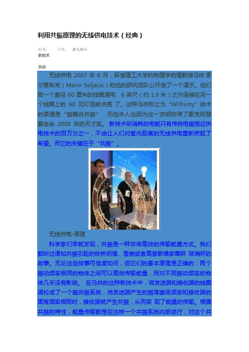
利用共振原理的无线供电技术(经典)标签:新技术杂谈分类:杂七杂八无线供电2007年6月,麻省理工大学的物理学助理教授马林·索尔贾希克(Marin Soljacic)和他的研究团队公开做了一个演示。
他们给一个直径60厘米的线圈通电,6英尺(约1.9米)之外连接在另一个线圈上的60瓦灯泡被点亮了。
这种马林称之为“WiTricity”技术的原理是“磁耦合共振”,而他本人也因为这一发明获得了麦克阿瑟基金会2008年的天才奖。
新技术所消耗的电能只有传统电磁感应供电技术的百万分之一,不由让人们对室内距离的无线供电重新燃起了希望。
而它的关键在于“共振”。
无线供电-原理科学家们早就发现,共振是一种非常高效的传输能量方式。
我们都听过诸如共振引起的铁桥坍塌、雪崩或者高音歌唱家震碎玻璃杯的故事。
无论这些故事可信度如何,但它们的基本原理是正确的:两个振动频率相同的物体之间可以高效传输能量,而对不同振动频率的物体几乎没有影响。
在马林的这种新技术中,将发送端和接收端的线圈调校成了一个磁共振系统,当发送端产生的振荡磁场频率和接收端的固有频率相同时,接收端就产生共振,从而实现了能量的传输。
根据共振的特性,能量传输都是在这样一个共振系统内部进行,对这个共振系统之外的物体不会产生什么影响。
这就像是几个厚度不同的玻璃杯不会因为同一频率的声音而同时炸碎一样(?)。
最妙的就是这一点了。
当发射端通电时,它并不会向外发射电磁波,而只是在周围形成一个非辐射的磁场。
这个磁场用来和接收端联络,激发接收端的共振,从而以很小的消耗为代价来传输能量。
在这项技术中,磁场的强度将不过和地球磁场强度相似,人们不用担心这种技术会对自己的身体和其他设备产生不良影响。
在2007年马林演示他的成果的时候,这项技术能够达到40%左右的效率。
这在某些场合是可以接受的,但是人们还想更进一步。
刚才我们提到的英特尔公司研究员们已经把传输效率提升到了75%,而马林小组最近声称,他们做到了90%。
无线充磁场共振式原理

无线充磁场共振式原理引言:随着科技的不断进步,无线充电技术作为一项便捷的充电方式,正在逐渐普及。
其中,磁场共振式无线充电技术以其高效率和远距离传输的特点备受关注。
本文将介绍磁场共振式无线充电的原理以及其应用。
一、磁场共振式无线充电的原理磁场共振式无线充电技术利用了电磁感应的原理,实现了电能的无线传输。
其基本原理可以概括为以下几个步骤:1. 发射端生成电磁场:发射端通过电源将电能转化为高频交流电,然后经过功率放大器放大,产生一定频率的电磁场。
这个电磁场是通过线圈产生的,线圈中流过交流电会产生变化的磁场。
2. 接收端感应电磁场:接收端也是一个线圈,当它处于发射端产生的电磁场范围内时,会感应到电磁场的变化。
根据电磁感应定律,感应到的电磁场变化会引起接收端线圈中的电流。
3. 电能传输:接收端线圈中的电流通过整流电路转化为直流电,然后供给接收设备使用。
这样就实现了电能的无线传输,完成了充电过程。
二、磁场共振式无线充电的优势相比传统的有线充电方式,磁场共振式无线充电技术具有以下几个优势:1. 高效率:磁场共振式无线充电技术利用了共振的原理,使得电能传输的效率更高。
在共振频率下,发射端和接收端的电磁场能够达到最大的匹配,从而实现了高效的能量传输。
2. 远距离传输:相比较其他无线充电技术,磁场共振式无线充电技术可以实现较远距离的电能传输。
这是因为电磁场的传输距离与线圈之间的耦合程度有关,而磁场共振技术可以通过调节频率和线圈设计来实现较远距离的传输。
3. 多设备充电:磁场共振式无线充电技术还支持同时给多个设备充电。
通过合理设计发射端和接收端的线圈布局,可以实现对多个接收设备的同时充电,提高了充电效率和便捷性。
三、磁场共振式无线充电的应用磁场共振式无线充电技术在许多领域都有着广泛的应用前景。
1. 智能手机充电:对于智能手机用户来说,磁场共振式无线充电技术可以提供更加便捷的充电方式。
只需将手机放置在充电座上,即可自动进行充电,无需插拔充电线,方便快捷。
无线充电器原理范文
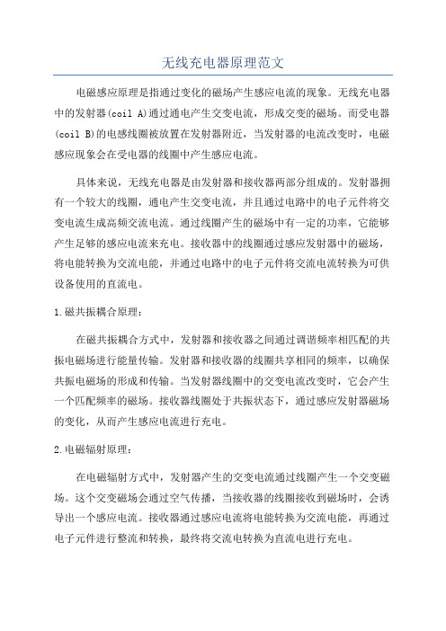
无线充电器原理范文电磁感应原理是指通过变化的磁场产生感应电流的现象。
无线充电器中的发射器(coil A)通过通电产生交变电流,形成交变的磁场。
而受电器(coil B)的电感线圈被放置在发射器附近,当发射器的电流改变时,电磁感应现象会在受电器的线圈中产生感应电流。
具体来说,无线充电器是由发射器和接收器两部分组成的。
发射器拥有一个较大的线圈,通电产生交变电流,并且通过电路中的电子元件将交变电流生成高频交流电流。
通过线圈产生的磁场中有一定的功率,它能够产生足够的感应电流来充电。
接收器中的线圈通过感应发射器中的磁场,将电能转换为交流电能,并通过电路中的电子元件将交流电流转换为可供设备使用的直流电。
1.磁共振耦合原理:在磁共振耦合方式中,发射器和接收器之间通过调谐频率相匹配的共振电磁场进行能量传输。
发射器和接收器的线圈共享相同的频率,以确保共振电磁场的形成和传输。
当发射器线圈中的交变电流改变时,它会产生一个匹配频率的磁场。
接收器线圈处于共振状态下,通过感应发射器磁场的变化,从而产生感应电流进行充电。
2.电磁辐射原理:在电磁辐射方式中,发射器产生的交变电流通过线圈产生一个交变磁场。
这个交变磁场会通过空气传播,当接收器的线圈接收到磁场时,会诱导出一个感应电流。
接收器通过感应电流将电能转换为交流电能,再通过电子元件进行整流和转换,最终将交流电转换为直流电进行充电。
无线充电器原理主要依靠电磁感应和电磁辐射来实现能量传输。
然而,无线充电的距离和传输效率还受到一些因素的影响,如距离、物体介质和接收器的位置等。
随着技术的进步和改进,无线充电技术在电子设备和汽车等领域的应用越来越广泛,为人们提供了更加便利和无线的充电方式。
无线电能传输技术国内外研究综述

无线电能传输技术国内外研究综述无线电能传输技术是一种通过无线方式传输电能的新兴技术,具有广泛的应用前景和潜力。
本文对无线电能传输技术的国内外研究进行了综述,介绍了该技术的研究现状、争论焦点、研究成果和不足,以及未来研究方向和挑战。
无线电能传输技术是一种通过无线方式传输电能的新兴技术,具有广泛的应用前景和潜力。
随着科技的不断发展,无线电能传输技术已经成为能源领域研究的热点之一。
本文旨在综述无线电能传输技术的国内外研究现状和争论焦点,介绍该技术的研究成果和不足,并探讨未来的研究方向和挑战。
无线电能传输技术是一种基于电磁感应、电磁波、磁场等物理原理,通过无线方式传输电能的新兴技术。
根据传输原理的不同,无线电能传输技术可分为磁耦合无线电能传输、电磁辐射无线电能传输、电场耦合无线电能传输等几种类型。
其中,磁耦合无线电能传输是最常用的一种,其原理是利用磁场进行电能传输。
无线电能传输技术的历史可以追溯到19世纪末,当时人们开始研究无线电能的传输。
随着科技的不断进步,无线电能传输技术得到了快速发展和应用。
国外学者如美国的Marin Soljacic和日本的TadashiMaeda等人在该领域做出了重要贡献。
国内对无线电能传输技术的研究起步较晚,但进展迅速,已有多所高校和科研机构在该领域进行了深入研究。
目前,无线电能传输技术已经得到了广泛应用,例如无接触充电、无线电力传输网络、医疗植入式设备等。
然而,无线电能传输技术仍存在一些争论焦点和挑战,如传输效率、安全性和距离等问题。
同时,该技术的应用也需要解决一些法律和技术规范等方面的问题。
国内外学者在无线电能传输技术方面进行了大量研究,并取得了一系列重要成果。
例如,Marin Soljacic等人利用磁耦合原理实现了远距离的无线电能传输;Tadashi Maeda等人研究出了基于电磁波的无线电能传输技术,实现了高效的无线电能传输。
国内一些高校和科研机构在无线电能传输技术方面也取得了重要进展,如南京航空航天大学的陈仁文教授团队在无接触充电方面进行了深入研究,并研制出了一系列无接触充电装置。
无线充电技术的电能转换效率

无线充电技术的电能转换效率无线充电技术是近年来备受关注的一项技术创新,它能够为手机、平板电脑等电子设备提供便捷的电能补充。
然而,不同的无线充电技术在电能转换效率方面存在着差异,这直接影响了使用者的充电体验和能源利用效率。
本文将对当前常见的几种无线充电技术的电能转换效率进行探讨,并分析其存在的问题和未来的发展方向。
一、电磁感应无线充电技术电磁感应无线充电技术是目前应用最为广泛的无线充电技术之一。
它利用发射端产生的交变磁场,通过感应耦合的方式将电能传输到接收端。
该技术的电能转换效率主要受到两个因素的影响:传输距离和传输功率。
在传输距离方面,电磁感应无线充电技术的电能转换效率随着传输距离的增加而逐渐下降。
这是由于随着距离的增加,磁场的强度减弱,从而导致能量传输的损耗增加。
为了提高电能转换效率,研究人员可以通过增加发射端和接收端之间的距离,以及合理设计电磁感应系统的结构和参数,来减小能量传输的损耗。
在传输功率方面,电磁感应无线充电技术的电能转换效率与功率的大小相关。
通常情况下,功率越大,电能转换效率越高。
但是,过高的功率也会引发一些问题,如系统发热问题和安全隐患。
因此,在设计电磁感应无线充电系统时,需要综合考虑功率大小与电能转换效率之间的平衡,以满足实际应用的需求。
二、磁共振无线充电技术相比于电磁感应无线充电技术,磁共振无线充电技术在电能转换效率方面具有更大的优势。
它利用发射端和接收端之间的磁场共振现象,实现较远距离的电能传输。
磁共振无线充电技术的电能转换效率主要受到两个因素的影响:共振频率和传输功率。
在共振频率方面,发射端和接收端需要具有相同的共振频率,才能够实现高效的能量传输。
因此,合理设计共振电路的频率和参数,对于提高电能转换效率至关重要。
在传输功率方面,磁共振无线充电技术能够通过调节谐振器的耦合系数来实现自适应的功率传输,从而提高电能转换效率。
此外,磁共振无线充电技术还可以通过将传输功率分割成多个小功率,将能量分布在空间中,减小传输过程中的能量损耗。
磁耦合谐振式无线电能传输技术新进展

磁耦合谐振式无线电能传输技术新进展一、本文概述无线电能传输技术,特别是磁耦合谐振式无线电能传输技术,近年来在科研领域和工业界引起了广泛的关注。
这种技术利用磁场共振原理,实现了电能的高效、安全、无接触传输,为众多应用场景提供了全新的可能性。
本文旨在综述磁耦合谐振式无线电能传输技术的最新进展,包括其基本原理、系统构成、性能优化以及在实际应用中的挑战与前景。
我们将从多个维度对这项技术的最新研究成果进行深入剖析,以期为读者提供一个全面而深入的理解。
本文还将探讨该领域的研究热点和未来发展趋势,以期为推动磁耦合谐振式无线电能传输技术的进一步发展和应用提供参考。
二、磁耦合谐振式无线电能传输技术原理磁耦合谐振式无线电能传输技术,又称为磁共振无线电能传输或磁谐振无线电能传输,是一种基于磁场耦合和谐振原理实现电能无线传输的技术。
其基本原理可以追溯到19世纪末的电磁感应定律和麦克斯韦的电磁场理论。
磁耦合谐振式无线电能传输系统主要由发送端(发射器)和接收端(接收器)两部分组成。
发射器通常包含一个高频交流电源、一个谐振线圈以及相应的调谐和匹配电路。
接收器则包括一个谐振线圈、整流器以及负载。
当发射器的高频交流电源驱动其谐振线圈时,会在其周围产生交变磁场。
若接收器的谐振线圈与发射器的谐振线圈具有相近的谐振频率,则会在接收器的谐振线圈中产生感应电动势,进而实现电能的无线传输。
该技术的关键在于谐振线圈的设计和调谐。
通过优化线圈的形状、尺寸、材料以及调谐电路的设计,可以实现高效的能量传输和较低的能量损耗。
为了避免电磁干扰和能量泄露,通常还需要在系统的设计和实施中考虑电磁屏蔽和防护措施。
磁耦合谐振式无线电能传输技术具有传输距离适中、传输效率高、对环境影响小等优点,因此在无线充电、电动汽车、智能家居等领域具有广泛的应用前景。
随着研究的深入和技术的成熟,该技术有望在更多领域实现突破和应用。
三、磁耦合谐振式无线电能传输技术的优势与挑战磁耦合谐振式无线电能传输技术作为一种新兴的无线能量传输方式,具有许多显著的优势,同时也面临着一些挑战。
- 1、下载文档前请自行甄别文档内容的完整性,平台不提供额外的编辑、内容补充、找答案等附加服务。
- 2、"仅部分预览"的文档,不可在线预览部分如存在完整性等问题,可反馈申请退款(可完整预览的文档不适用该条件!)。
- 3、如文档侵犯您的权益,请联系客服反馈,我们会尽快为您处理(人工客服工作时间:9:00-18:30)。
Wireless Power Transfer via Strongly Coupled Magnetic Resonances André Kurs,1* Aristeidis Karalis,2 Robert Moffatt,1 J. D. Joannopoulos,1 Peter Fisher,3Marin Soljačić11Department of Physics, Massachusetts Institute of Technology, Cambridge, MA 02139, USA.2Department of Electrical Engineering and Computer Science, Massachusetts Institute ofTechnology, Cambridge, MA 02139, USA. 3Department of Physics and Laboratory forNuclear Science, Massachusetts Institute of Technology, Cambridge, MA 02139, USA.*To whom correspondence should be addressed. E-mail: akurs@通过强耦合磁共振进行无线电力传输AndréKurs,1 * Aristeidis Karalis,2 Robert Moffatt,1 J. D. Joannopoulos,1 Peter Fisher,3 MarinSoljačić11麻省理工学院物理系,剑桥,MA 02139,USA。
2马萨诸塞理工学院电气工程与计算机科学系,剑桥,MA 02139,USA。
马萨诸塞理工学院核科学物理与实验室3,剑桥,MA 02139,USA。
*应向谁发信。
电子邮件:akurs@Using self-resonant coils in a strongly coupled regime, we experimentally demonstrate efficient non-radiative power transfer over distances of up to eight times the radius of the coils. We demonstrate the ability to transfer 60W with approximately 40% efficiency over distances in excess of two meters. We present a quantitative model describing the power transfer which matches the experimental results to within 5%. We discuss practical applicability and suggest directions for further studies.在强耦合状态下使用自谐振线圈,我们实验证明高达线圈半径的八倍的有效的非辐射功率传输。
我们展示了在距离超过两米的情况下以大约40%的效率传输60W的能力。
我们提出一个描述电力传输的定量模型,将实验结果与5%以内相匹配。
讨论实际适用性,并提出进一步研究的方向。
11. 30 March 2007; accepted 21 May 20072.Published online 7 June 2007; 10.1126/science.1143254 Include this information3.when citing this paper.In the early 20th century, before the electrical-wire grid, Nikola Tesla (1) devoted much effort towards schemes to transport power wirelessly. However, typical embodiments (e.g. Tesla coils) involved undesirably large electric fields. During the past decade, society has witnessed a dramatic surge of use of autonomous electronic devices (laptops, cell- phones, robots, PDAs, etc.) As a consequence, interest in wireless power has re-emerged (2–4). Radiative transfer (5), while perfectly suitable for transferring information, poses a number of difficulties for power transfer applications: the efficiency of power transfer is very low if the radiation is omnidirectional, and requires an uninterrupted line of sight and sophisticated tracking mechanisms if radiation is unidirectional. A recent theoretical paper (6) presented a detailed analysis of the feasibility of using resonant objects coupled through the tails of their non-radiative fields for mid- range energy transfer (7). Intuitively, two resonant objects of the same resonant frequency tend to exchange energy efficiently, while interacting weakly with extraneous off- resonant objects. In systems of coupled resonances (e.g. acoustic, electro-magnetic, magnetic, nuclear, etc.), there is often a general “strongly coupled” regime of operation (8). If one can operate in that regime in a given system, the energy transfer is expected to be very efficient. Mid-range power transfer implemented this way can be nearly omnidirectional and efficient, irrespective of the geometry of the surrounding space, and with low interference and losses into environmental objects (6).20世纪初,电线网格之前,尼古拉·特斯拉(NikolaTesla)(1)非常努力地进行无线传输的方案。
然而,典型的实施例(例如特斯拉线圈)涉及不期望的大电场。
在过去十年中,社会出现了自主电子设备(笔记本电脑,手机,机器人,P DA等)的大量使用。
因此,对无线电力的兴趣重新出现(2-4)。
辐射传输(5)虽然完美适用于传输信息,但对电力传输应用造成了许多困难:如果辐射是全向的,则电力传输的效率非常低,如果辐射是辐射,则需要不间断的视线和复杂的跟踪机制是单向的最近的理论论文(6)详细分析了通过其非辐射场的尾部耦合的共振物体在中等能量转移中的可行性(7)。
直观地,相同共振频率的两个共振物体倾向于有效地交换能量,同时与外来的非共振物体相互作用弱。
在耦合谐振(例如声学,电磁,磁性,核等)的系统中,通常存在一般的“强耦合”的操作(8)。
如果在给定的系统中可以在该制度下运作,预计能量转移将非常有效。
不论周围空间的几何形状如何,以及对环境物体的干扰和损失都很小,实现这种方式的中距离功率传输几乎是全方位和有效的(6)。
Considerations above apply irrespective of the physical nature of the resonances. In the current work, we focus on one particular physical embodiment: magnetic resonances (9). Magnetic resonances are particularly suitable for everyday applications because most of the common materials do not interact with magnetic fields, so interactions with environmental objects are suppressed even further. We were able to identify the strongly coupled regime in the system of two coupled magnetic resonances, by exploring non-radiative (near-field) magnetic resonant induction at MHz frequencies.At first glance, such power transfer is reminiscent of the usual magnetic induction (10); however, note that the usual non- resonant induction is very inefficient for mid-range applications.上述注意事项不考虑谐振的物理性质。