mcgs机械手控制实例
MCGS高级教程实例
MCGS高级教程实例MCGS(Machine Control Graphics System)是一种用于机器自动控制的软件系统,它可以实现对自动化设备的图形化监控与控制。
本文将介绍MCGS的高级教程实例。
1.实时监控温度控制系统假设有一个温度控制系统,系统中有一个传感器用于测量温度,并通过控制器来调整加热器的功率以控制温度。
使用MCGS可以实时监控温度变化,并将温度数据以曲线图的形式显示出来。
同时,可以通过调节控制器参数来实现温度的控制。
这个实例可以帮助用户了解MCGS的图形监控与曲线绘制功能,并学习如何通过修改控制器参数实现温度控制。
2.数据采集与分析系统假设有一个工厂中有多个生产线,每个生产线上有多个传感器,用于测量不同的参数。
使用MCGS可以实时采集传感器数据,并对数据进行分析与处理。
比如,可以统计每个生产线的工作效率、故障率等指标,并生成报表或图表展示。
这个实例可以帮助用户了解MCGS的数据采集与处理功能,以及如何使用数据分析工具进行数据处理与展示。
3.智能家居控制系统假设用户想要实现对家中智能设备的远程控制和监控。
使用MCGS可以通过网络连接智能设备,并实现对其的远程控制和状态监控。
比如,用户可以通过手机App或网页登录MCGS系统,实时监控家中各个智能设备的状态,并远程控制设备的开关、亮度等参数。
这个实例可以帮助用户了解MCGS的网络通讯与远程控制功能,以及如何通过手机App或网页实现对设备的控制与监控。
4.机器人控制与路径规划假设用户有一个机器人平台,想要实现对机器人的控制和路径规划。
使用MCGS可以实现对机器人的运动控制,并通过路径规划算法确定机器人的运动轨迹。
比如,用户可以通过MCGS系统向机器人发送指令,控制其前进、后退、旋转等动作,并通过设置目标点和障碍物位置,实现对机器人的路径规划。
这个实例可以帮助用户了解MCGS的运动控制和路径规划功能,以及如何通过指令控制和路径规划算法实现机器人的自主运动。
基于MCGS的机械手控制系统

长沙航空职业技术学院(2012届)毕业设计(论文)基于MCGS的机械手控制系统2012年 5月目录封面 (1)摘要 (4)1绪论 (6)1.1课题研究的目的及意义 (6)1.2国内外机械手研究状况 (6)2机械手控制方式的选择和可编程序控制器介绍 (8)2.1机械手控制方式的选择 (8)2.1.1控制方式的分类 (8)2.2传感器 (8)2.2.1行程开关 (8)2.2.2压力传感器 (9)3 MCGS在机械手控制中的作用 (11)3.1MCGS的概述 (11)3.1.1 MCGS的简介 (11)3.1.2 MCGS的构成 (11)3.1.3 MCGS主要特性和功能 (12)3.1.4 MCGS的编程语言 (13)3.1.5 MCGS的数据结构 (13)3.1.6 MCGS的作用 (14)3.2工程的建立与变量的定义 (14)3.2.1工程的建立 (14)3.2.2变量的分配 (15)3.2.3变量的定义步骤 (17)3.2.4设备与变量连接 (19)3.3工程画面的建立 (22)3.3.1监控画面的制作 (24)3.3.2运行策略的建立及脚本程序的编写 (26)3.4动画的连接 (31)3.4.1指示灯的动画连接 (31)3.4.2机械手的动画连接 (33)3.5组态运行 (37)结论 (38)致谢 (39)参考文献 (40)附录A 系统流程图 (41)附录B 硬件接线图 (42)摘要MCGS(Monitor and Control Generated System)是一套Windows平台的、用于快速构造和生成上位机监控系统的组态软件系统。
MCGS为用户提供了解决实际工程问题的完整方案和开发平台,能完成现场数据采集、实时和历史数据处理、报警和安全机制、流程控制、动画显示、趋势曲线和报表输出以及企业监控网络等功能。
MCGS在机械手控制系统中的应用。
利用组态软件MCGS设计了机械手模型控制系统监控界面,提供了较为直观、清晰、准确的机械手运行状态,进而为维修和故障诊断提供了多方面的可能性,充分提高了系统的工作效率。
基于MCGS的机械手控制系统设计

无锡职业技术学院毕业实践任务书课题名称基于MCGS的机械手控制系统设计指导老师徐颖秦职称高级工程师专业名称电气工程与自动化班级生产自动化20831 学生姓名资亚云学号课题需要完成的任务:机械手臂是目前在机械技术领域中应用最广泛的自动化机械装置,尽管其形态各异,但都有一个共同特点,就是能够接受指令,精确地定位到空间上的某一点进行作业。
本课题的主要研究目标是基于MCGS组态软件的机械手控制系统设计。
主要任务如下:1.机械手MCGS自动控制系统的控制要求。
2.控制方案的确定,PLC型号的选择,输入/输出的定义。
3.绘制原理图,完成软件编程。
课题计划:11年2月27日-----------11年3月5日了解工艺过程和控制要求。
11年3月6 日------------11年3月30日完成计划。
11年4月1日-------------11年4月15日完成毕业论文。
计划答辩时间:2011年4月16日--------20日自动控制技术系(部、分院)2011年01月19日外文翻译Configuration softwareConfiguration software, also called configuration monitoring software system software. Translation from English SCADA, namely Supervisory Control and Data Acquisition (Data Acquisition and monitoring Control). It is to point to some data acquisition and process control of special software. They are at the automatic control system monitoring layer level of software platform and development environment, use flexible configuration mode, to provideusers with rapid build industrial automatic control system monitoring function, general level of software tools. Configuration software application field is very wide, can be applied to power system, water supply system, petroleum, chemical field data acquisition and monitoring control and process controletc. In power System and electrified railway on dynamic System (also called far, Remote Terminal Unit RTU System).Configuration software in China is a conventional concepts, and no clear definition, it can be understood as "configuration type monitoring software". "Configuration (Configure)" is the meaning of "Configure", "set", "Settings" meaning such as, refers to the user through similar "building blocks" simple ways to complete your needs the software function, without the need to write computer program, and also is the so-called "configuration". It is sometimes called "second development", configuration software is referred to as "second development platform". "Monitoring (Supervisory Control)", namely "monitoring and Control", it is to point to through computer signals of automation equipment or process monitoring, Control and management Configuration software is a professional. A configuration software can only suitable for some areas of application. Configuration concept first appeared in industrial computer control. Such as distributed control system (DCS) configuration, PLC (programmable controller) ladder diagram configuration. The man-machine interface generation software called industrial control configuration software. In other industries have configuration concepts such as AutoCAD, PhotoShop, etc. The difference is, industrial control formation in the configuration result is used in real-time monitoring. Outwardly, configuration tool to run the program is to execute their specific tasks. Industrial control configuration software also provides programming method, are generally built-in compilation system that provides such BASIC language, some support VB, now some configuration software even support c # high-level language. Configuration software are mostly support various mainstream g-kong equipment and standard communication protocol, and usually should provide无锡职业技术学院毕业设计说明书(论文)distributed data management and network function. Corresponding to the original HMI (man-machine Interface software, Human Machine with), the concept of configuration software or a user can quickly to establish their own HMI software tools or development environment. The configuration software before the emergence of the field of industrial automation users through manual or entrust a third party to write HMI application, long development time, low efficiency, poor reliability, Or purchase of special industrial control system, usually is a closed system, the choice is small, often cannot meet the demand, it is difficult to with the outside world to upgrade and data interaction by adding features serious limitations. Configuration software user can use the emergence of configuration software functions, to construct a set of the most suitable application system. With its rapid development, the real-time database, real-time control, SCADA, communications and networking, open data interface, for I/O devices widespread support has become its main content control configuration software will continue to be with new contents.Foreign configuration software: 1, Wonderware InTouch: (the world wide company) is Invensys PLC "production management" of a operation units, is a leading global provider of industrial automation software. The Wonderware InTouch software is the earliest entering into China configuration software. In the late 1980s and early 1990s, based on the Windows3.1 InTouch software made us, and refreshing InTouch provided a lot of library. However, the early InTouch software adopts DDE way and the driver communication, performance is poorer, the latest InTouch7.0 edition has completely based on 32-bit Windows platforms, and provides the OPC support. 2, WinCC: Siemens automation and drives group (A&D) is the largest of Siemens ag, the group is one of Siemens industrial areas of important component. Simens of WinCC and a set of complete configuration development environment, Simens provider class C language script, including a debugging environment. WinCC embedded OPC support, and can be used for distributed system configuration. But WinCC structure is more complex, users had better after Simens training in order to master WinCC applications.Domestic brand configuration software 1. ShiJiXing: by Beijing century long autumn technology Co., LTD. Development. Product sales since 1999. 2. 3d force control: by Beijing 3d force control technology Co., LTD develop core software products, founded in 1992. 3. KingView KingView: by Beijing and control technology development Co., LTD, development, the company was founded in 1997, is currently in the domestic software market plays a certain status. 4. Realinfo: by zijin bridge zijinbridge software technology Co., LTD develop, this company is by petrochina daqing petrochemical factory was invested. 5. The MCGS: by Beijing kunlun tong state automation software technology Co., LTD. Is mainly on the market development, tie-in hardware sales. 6. Still have Controx (open content), easy control, etcConfiguration software features With the industrial automation level rapidly increase, computers in industry wide application of industrial automation, people on the demand is higher and higher, a wide variety of control equipment and process monitoring device in the industrial fields of application, make the traditional industrial control software already cannot satisfy the customers' different requirements. In the development of traditional industrial control software, when industrial controlled object once has changed, he must modify source program of the control system, which causes the development cycle is long, Has developed successfully g-kong software and since each control project of different and make its repeat utilization rate is very low, resulting in its price is very expensive, During the revision control software source code, if the original programming staff for job change and leave, it must be with other personnel or novice on the alteration of the source program, thereby is rather difficult. General industrial automation configuration software appear to solve the practical engineering problems may provide a new method, because it can well solve the traditional industrial control software problems, users can under our own control object and control the purpose of arbitrary configuration, finishes final automatic control engineering. Configuration (Configuration) for modular combinations. General configuration software main features: (1) the continuity and scalability. By general configuration software applications, when the site (including hardware equipment or system structure) or user demand change, need not be many changes and conveniently accomplish software update and upgrade, (2) encapsulation (yi), gm easy-to-use configuration software can complete functionality all in a user-friendly way packaged and for the user, do not need to grasp too much programming language technology (don't even need programming technology), can perform well in a complicated engineering all the required function; (3) generality, each user according to engineering practice, use general configuration software provides the bottom of the equipment (PLC, intelligent instruments, intelligent module, boards, inverter, etc.) I/O is, open database and picture production tools, can finish an animation effects, real-time data processing, the history data and curve coexist, with multimedia capability and network function of engineering, not affected by trade restrictions.Monitor configuration software is increasingly becoming the automation无锡职业技术学院毕业设计说明书(论文)hardware vendor for the key The whole of automation systems, software proportion gradually enhance, although configuration software just one part, but because of the penetration ability, extensible, in recent years whittled away many special software market. Therefore, monitoring configuration software has high industrial correlativeness degree is the automation systems into high-end application, expand the market share important bridge. In this thought are driven by Siemens WinCC achieve great success in the market. At present, the international famous industrial automation manufacturers such as Rockwell, GE Fanuc, of Honeywell, Siemens, ABB, schneider, the invensys etc are developed their own configuration software. Monitor configuration software in DCS operating station software proportion is increasing day by day After FOXBORO after Euro therm (Europe), etc PCS7 Delta V, DCS system in use generic control configuration software as operation station. At the same time, domestic DCS manufacturer also began to try to use the monitoring configuration software as operation station. In universities and research institutes, more and more people begin to engage in monitoring configuration software related technical research From domestic automation industry academic periodicals run, the configuration software and its is closely related to the new technology as the core research shows ascendant trend, many researchers exist is configuration software technology development and innovation important active factors, also can certain accumulate many technical achievements. Whether technological achievements or researchers will follow the pyramids, the law of from foundation to high-end formed transfer. These researchers and their research for monitoring configuration software vendors to develop new products, and provided the beneficial experience for reference, and develops their ideas. Linux based monitoring configuration software and related technology is rapidly developing, many manufacturers are launched mature commodities, the pattern of configuration software industry will have a far-reaching impact.组态软件组态软件,又称组态监控软件系统软件。
基于MCGS组态软件的机械手控制系统
机械手的工作由气缸驱动,气缸由对应电磁阀 控制。上升/下降和左移/右移分别由双线圈两位置 电磁阀控制。机械手的放松/夹紧由单线圈两位置 电磁阀(称夹紧电磁阀)控制。当机械手右移到位 并 准 备 下 降 时 ,为 确 保 安 全 ,须 在 右 工 作 台 无 工 件 时才允许下降,并用光电开关进行有无工件检测。
时器启动1endif定时器启动0endifendif设备窗口是连接和驱动外部设备的工作环境mcgs组态软件采用在串口通讯父设备下挂接通讯子设备的处理机制组态工程所用通讯子设备构件为三菱fx485该设备用于mcgs读写三菱fx系列中支持rs485通信协议的plc设备
兵工自动化 2007 年第 26 卷第 8 期
·56·
兵工自动化 2007 年第 26 卷第 8 期
自动测量与控制 Automatic Measurement and Control
O. I. Automation 2007, Vol. 26, No. 8
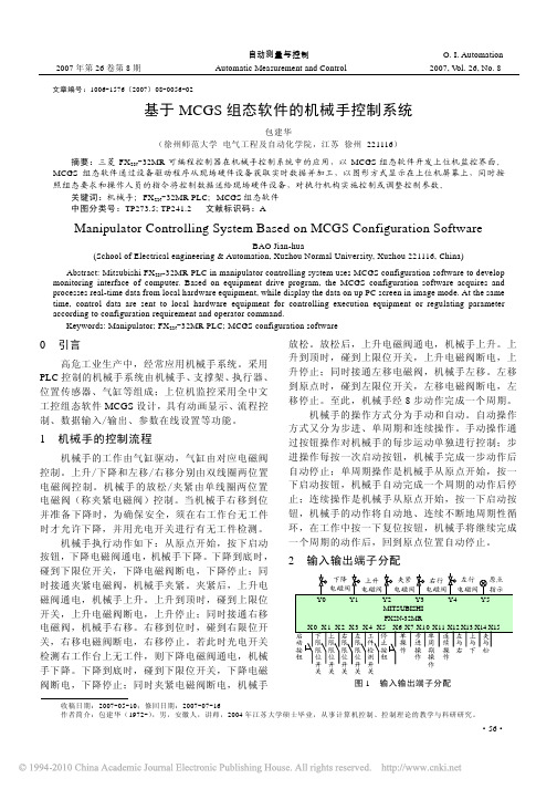
机械手的控制由开关控制,且所需 I/O 点数不 多,计 14 个输入量,6 个输出量,因此系统选用性 价比较高的三菱 FX2N-32MR 小型 PLC,图 1 为 FX2N-32MR 输入/输出端子地址分配定义。
Keywords: Manipulator; FX2N-32MR PLC; MCGS configuration software
0 引言
高危工业生产中,经常应用机械手系统。采用 PLC 控制的机械手系统由机械手、支撑架、执行器、 位置传感器、气缸等组成;上位机监控采用全中文 工控组态软件 MCGS 设计,具有动画显示、流程控 制、数据输入/输出、参数在线设置等功能。
参考文献:
[1] 袁 秀 英 . 组 态 控 制 技 术 [M]. 北 京 : 电 子 工 业 出 版 社 ,
毕业论文MCGS监控PLC控制机械手

毕业论文--MCGS监控PLC控制机械手江西工业工程职业技术学院毕业论文题目MCGS监控PLC控制机械手学生姓名蔡晓春指导教师夏路生院系电子计算机系专业电气自动化级别电气101江西工业工程职业技术学院20 年月日摘要我们生活在一个科学技术飞速发展的社会。
在科技进步的同时,各种不同类型的机械手以其突出的性能越来越多的被人们所应用。
机械手在不同的作业场合,为生产的顺和利快速进行带来了极大的方便。
尤为明显的是在工业及军事领域内,存在着很多不便于人类操纵的环节,如果使用具有远程控制功能的机械手,则可以增加系统的安全性,大大的节约损耗,提高效率。
可见,工业化进程中,在特殊环境中使用机械手已成为一种必然的趋势。
在本设计中介绍了国内外机械手研究现状及PLC的发展趋势,描述了机械手控制系统的工作原理和动作实现过程,还研究了MCGS在机械手控制系统中的应用。
本毕业设计主要设计基于PLC的机械手模型控制系统,利用组态软件MCGS设计了机械手模型控制系统监控界面,提供了较为直观、清晰、准确的机械手运行状态,进而为维修和故障诊断提供了多方面的可能性,提高了系统的工作效率。
关键词:机械手,PLC,MCGS目录第一章绪论 (6)1.1 课题背景 (6)1.2设计目的和意义 (7)1.3 本文主要工作 (8)第2章可编程序逻辑控制器(PLC)和机械手概述92.1 可编程序逻辑控制器(PLC) (9)2.1.1 PLC的结构 (9)2.1.2 PLC的发展历程 (10)2.1.3 PLC的硬件 (12)2.1.4 PLC的主要特点 (14)2.1.5 FX2N系列PLC介绍 (15)2.2 机械手 (17)2.2.1 机械手概述 (17)2.2.2机械手的工作原理 (18)2.2.3机械手的发展趋势 (19)第三章系统设计 (20)3.1 系统方案分析设计 (20)3.1.1控制要求 (20)3.1.2 方案设计 (20)3.2 硬件设计 (22)3.2.1 输入/输出端子地址分配 (22)3.2.2 PLC接线图 (22)3.3 系统程序设计 (23)3.3.1 常用编程方法介绍 (23)3.3.2流程图 (25)3.3.3梯形图 (26)3.4 MCGS组态软件 (29)3.4.1 MCGS 组态软件结构 (30)3.4.3 工程的建立和变量的定义 (35)3.4.4动画连接 (39)3.4.5 调试 (46)第四章系统的调试及设计总结 (47)4.1 系统调试 (47)结论 (48)参考文献 (50)致谢 (51)第一章绪论1.1 课题背景随着计算机技术的飞速发展,PLC(即可编程逻辑编程器的简称)已经进入日常生产、生活的各个方面,PLC的应用在各行各业已成为必不可少的内容。
基于MCGS的机械手系统控制毕业设计
目录摘要 (3)1 前言 (3)2 MCGS组态软件概述 (4)2.1 MCGS组态软件的基本特点和功能 (4)2.2 MCGS的分类和发展 (5)2.3 MCGS的编程语言 (6)2.4 MCGS的数据结构 (7)2.5 MCGS的作用 (7)3MCGS组态设计 (8)3.1 建立画面 (8)3.1.1 建立画面的方法 (8)3.1.2 定义组态变量 (9)3.1.3 变量类型 (9)3.1.4 开关型变量的建立 (10)3.1.5 数值型变量的建立 (10)3.1.6 动画设计 (11)3.2 脚本程序设计与调试 (12)3.2.1 脚本程序设计 (12)3.2.2 调试 (16)3.3 MCGS手动控制设计 (16)3.3.1 MCGS工程的建立和变量的定义 (16)3.3.2 变量定义的步骤 (18)3.3.3 动画的制作及链接 (19)3.3.4 调试 (22)4 机械手的验证 (23)4.1机械手手动画面的验证 (23)4.1.1手动画面的进入 (23)4.1.2 夹紧效果 (24)4.1.3 上移效果 (24)4.1.4 右移效果 (25)4.1.5 下移效果 (25)4.1.6 放松效果 (26)4.2机械手自动画面的验证 (26)4.2.1机械手自动监控画面 (26)4.2.2机械手自动控制移动画面 (27)4.3 PLC的验证 (27)4.3.1定时器 (27)4.3.2指示灯显示 (27)4.4验证结果 (28)5 结论 (29)6 参考文献 (30)7 致谢 (31)基于MCGS的机械手系统控制摘要:MCGS是一种用于快速构造和生成嵌入式计算机监控系统的组态软件,它的组态环境能够在基于Microsoft的各种32位Windows平台上运行,运行环境则是在实时多任务嵌入式操作系统WindowsCE中运行。
通过对现场数据的采集处理,以动画显示、报警处理、流程控制和报表输出等多种方式向用户提供解决实际工程问题的方案,在自动化领域有着广泛的应用,机械手控制系统具体的实现是利用PLC控制,通过PLC控制,使得机械手能够按照一定的模式动作,经过调试,最终可以可靠运行。
mcgs机械手控制实例

9.5 动画连接
9.5.2 构件移动动画连接
按图对右滑杆、机械手、上工件分别进行水平 移动动画连接。参数设置的意思是:当水平移 动量=0时,向右移动距离为0;当水平移动量 =50时,向右移动距离为180。
左杆水平移动的设置
9.5 动画连接
9.5.2 构件移动动画连接 [4] 水平缩放动画连接。估计或画线计算左滑杆
9.3 制作工程画面
9.3.1 建立画面 [1] 在“用户窗口”中单击“新建窗口”按钮,建立“窗
口0”。 [2] 选中“窗口0”,单击“窗口属性”,进入“用户窗口
属性设置”。
[3] 将窗口名称改为:机械手控制;窗口标题改为:机械 手控制;窗口位置选中“最大化显示”,其它不变,单 击“确认”。
单击窗口其他任何一个空白地方,结束第1 个矩形的编辑。依次画出机械手画面9个矩形部 分(7个蓝色,2个红色)。单击“保存”按钮 。
9.3 制作工程画面
9.3.3 构件的选取
(1)机械手的绘制:单击插入元件按钮,在“对 象元件列表”中的“其他”,展开该列表项, 单击“机械手”,单击“确定”按钮。
在机械手被选中的情况下,单击“排列” 菜单,选择“旋转”——“右旋90度”,使机械 手旋转90度。调整位置和大小。在机械手上面 输入文字标签“机械手”。单击“保存”按钮 。
下杆垂直缩放的设置
9.5 动画连接
9.5.2 构件移动动画连接
[3]水平移动动画连接。在工件初始位置和移动 目的地之间画一条直线,记下状态条大小指示 ,此参数即为总水平移动距离,假设移动距离 为180。脚本程序执行次数=左移时间(右移时 间)/循环策略执行间隔=10s/200ms=50次 。水平移动量的最大值=循环次数*变化率 =50*1=50,当水平移动量=50时,水平移动 距离为180。
基于MCGS组态软件的机械手模拟控制系统

关 键 词 :机 械 手 ;P C; 组 态软 件 L 中 图 分 类 号 :T 3 1 P9. 4 文 献 标 识 码 :A d i O3 6 /.s . 0 — 6 32 1 .20 2 o: . 9 j sn1 2 6 7 .0 00 .6 l 9 i 0
Re e r h o a i u a o i u a i n Co t o l g S s e s d o CG S Co f u a i n S fwa e 。 s a c n M n p l t r S m l to n r l n y t m Ba e n M i n g r to o t r i
npuao .Prcies owsta e c mbiain ft ePLC nd M CGS c n g rto o t r sv l be f ein,a et ,n p l a i lt r a t h c h tt o h nt o o h a o fu ain sfwa ei aua l ord s i g nd tsi a d a pi — ng c
LIS -F n u a g, H U ANG a g Xi Gu n - a
( p r n f eh t nc En ie r g L o agIstt f ce c n e h oo y u y n nn 7 0 3 Deat t c ar is gn ei u yn ntueo in ea dT c n lg ,L o a gHe a 4 1 2 ,Chn ) me o M o n i S ia
- 1、下载文档前请自行甄别文档内容的完整性,平台不提供额外的编辑、内容补充、找答案等附加服务。
- 2、"仅部分预览"的文档,不可在线预览部分如存在完整性等问题,可反馈申请退款(可完整预览的文档不适用该条件!)。
- 3、如文档侵犯您的权益,请联系客服反馈,我们会尽快为您处理(人工客服工作时间:9:00-18:30)。
5. 动画连接
5.3 控制程序的编写
在“设定值”栏填入: 12 ,代表设定时间为 12s 。 在“当前值”栏,填入:计时时间。在“计时条件 ”一栏,直接或操作“?”按钮填入:时间到。则 计时时间超过设定时间时,“时间到”变量将为1, 定时器开始计时;为0时,停止计时。在“复位条件 ”一栏,填入:定时器复位。在“计时状态”一栏 ,直接或操作“?”按钮填入:时间到。则计时时
3. 制作工程画面
3.3 构件的选取
(1)机械手的绘制:单击插入元件按钮,在“对
象元件列表”中的“其他”,展开该列表项,
单击“机械手”,单击“确定”按钮。 在机械手被选中的情况下,单击“排列” 菜单,选择“旋转”——“右旋90度”,使机械 手旋转90度。调整位置和大小。在机械手上面 输入文字标签“机械手”。单击“保存”按钮 。
[3] 双击选中对象,打开“数据对象属性设置”
。 [4] 将对象名称改为:垂直移动量;对象类型选 择:数值型;在对象内容注释输入框内输入:“ 控制构件上下运动的参量”,单击“确认”。
5. 动画连接
本样例中需要制作动画效果的部分包括: 1.按钮的开停及指示灯的变化。
2.机械手的动画效果。
间超过设定时间时,“时间到”变量将为1,否则为
0。在“内容注释”一栏,填入:定时器。单击“确 认”按钮。
计时器值的设定
5. 动画连接
5.4 利用定时器和脚本程序实现机械手的定时控制
从组态环境进入循环策略组态窗口,如图所示。
5. 动画连接
5.4 利用定时器和脚本程序实现机械手的定时控制
单击工具栏“新增策略行”按钮,在定时器下 增加一行新策略。选中策略工具箱的“脚本程 序”,光标变为手形。单击新增策略行末端的 小方块,脚本程序被加到该策略。双击“脚本
[2] 选择文件菜单中的“工程另存为”菜单项,
弹出文件保存窗口。 [3] 在文件名一栏内输入“机械手控制系统”, 点击“保存”按钮,工程创建完毕。
3. 制作工程画面
3.1 建立画面 [1] 在“用户窗口”中单击“新建窗口”按钮,建立“窗 口0”。 [2] 选中“窗口0”,单击“窗口属性”,进入“用户窗口 属性设置”。 [3] 将窗口名称改为:机械手控制;窗口标题改为:机械 手控制;窗口位置选中“最大化显示”,其它不变,单 击“确认”。
设定参数。填入各个参数,并注意变化方向和 变化方式选择。当水平移动参数=0时,长度为
初值的100%;当水平移动参数=50时,长度
为300%。单击“确认”按钮,存盘。
左杆缩放设置
5. 动画连接
5.2 构件移动动画连接
[5] 工件移动动画的实现。选中下工件,在“属 性设置”页中选择进入“可见度”页,在表达 式一栏填入:工件夹紧标志;当表达式非零时 ,选择:对应图符不可见。意思是:当工件夹
[4] 在“用户窗口”中,选中“机械手控制”,点击右键
,选择下拉菜单中的“设置为启动窗口”选项,将该窗 口设置为运行时自动加载的窗口。
3. 制作工程画面
3.2 编辑画面
选中“机械手控制”窗口图标,单击“动画
组态”,进入动画组态窗口,开始编辑画面。
(1)利用 图标制作工程标题:机械手控制系 统,属性依然设置为:无填充、无边线、宋体 蓝色26号字。 (2)画地平线:利用画图工具 颜色为黑色。 拖拽出一条一 定长度的直线,调整线的长度、位置、粗细。
3. 制作工程画面
3.3 构件的选取
(2) 画机械手左侧和下方的滑杆:利用“插入
元件”工具,选择“管道”元件库中的“管道
95”和“管道96”,分别画出两个滑杆,将大小 和位置调整好。
3. 制作工程画面
3.3 构件的选取
(3)画指示灯:需要启动、复位、上、下、左、
右、夹紧、放松8个指示灯显示机械手的工作状
5. 动画连接
if 计时时间<=12 then 上移=0 工件夹紧标志=1 exit endif if 计时时间<=22 then 右移=0 上移=1 exit endif if 计时时间<=27 then
5. 动画连接
5.3 控制程序的编写
定时器的功能分为,启停功能:在需要的时候 被启动,在需要的时候被停止。计时功能:启 动后进行计时。计时时间设定功能,即可以根 据需要设定时计时。状态报告功能:即是否到
设定时间。复位功能:即在需要的时候重新开
始记时。双击新增策略行末端的定时器方块, 出现定时器属性设置。
按下复位按钮后,机械手在完成本次操作后,回
到原始位置,然后停止。 松开复位按钮,退出复位状态。
2. 建立工程
[1] 鼠标单击文件菜单中“新建工程”选项,如 果MCGS安装在D盘根目录下,则会在D: \MCGS\WORK\下自动生成新建工程,默认的工程名 为:“新建工程X.MCG”(X表示新建工程的顺序号, 如:0、1、2等)
2)确定与数据变量存盘相关的参数,如存盘的
周期、存盘的时间范围和保存期限等。
4. 定义数据对象
4. 定义数据对象
以数据对象“垂直移动量”为例,介绍一下定义
数据对象的步骤: [1] 单击工作台中的“实时数据库”窗口标签 。 [2] 单击“新增对象” 按钮,在窗口的数据对象 列表中,增加新的数据对象。
性设置”窗口。在“位置动画连接”一栏中选
中“垂直移动”。
5. 动画连接
5.2 构件移动动画连接
单击“垂直移动”选项卡,进入该页,在“表 达式”一栏填入:垂直移动量。在垂直移动连 接栏填入各项参数:当垂直移动量=0时,向下 移动距离=0;当垂直移动量=25时,向下移动 距离=72。单击“确认”按钮,存盘。(垂直 移动量的最大值=循环次数*变化率 =25*1=25;循环次数=下移时间(上升时间
度=初值的100%;当垂直移动量=25时,长
度=200%。
下杆垂直缩放的设置
5. 动画连接
5.2 构件移动动画连接
[3]水平移动动画连接。在工件初始位置和移动 目的地之间画一条直线,记下状态条大小指示 ,此参数即为总水平移动距离,假设移动距离 为180。脚本程序执行次数=左移时间(右移时 间)/循环策略执行间隔=10s/200ms=50次 。水平移动量的最大值=循环次数*变化率 =50*1=50,当水平移动量=50时,水平移动
位按钮与对应变量之间的动画连接。单击“保
存”按钮。
9.5 动画连接
9.5.1按钮的开停及指示灯的变化
[2] 指示灯的动画连接:双击启动指示灯,弹出“ 单元属性设置”窗口。单击“动画连接”选项卡,
进入该页,如图所示。单击“三维圆球”,出现“
?”和“>”按钮。单击“>”按钮,弹出“动画组态 属性设置”窗口。单击“属性设置”选项卡,进入
紧标志 =1 时,下工件不可见;工件夹紧标志
=0时,下工件可见。选中并双击上工件,将其 可见度属性设置为与下工件相反,即当工件夹 紧标志非零时,对应图符可见。存盘调试。
5. 动画连接
5.3 控制程序的编写
[1] 定时器的使用。单击“运行策略”选项卡, 进入“运行策略”页。选中“循环策略”,单 击右侧“策略属性”按钮,弹出“策略属性设 置”窗口。在“定时循序执行,循环时间
2、 定时器构件的使用
3、 3个策略:启动策略、退出策略、循环策略
1 . 工程分析
数据对象:
1. 工程分析
图形制作:
机械手控制系统窗口
1、机械手及其台架及工件 2、启动和复位按钮 3、上移、下移、左移、右移、启动、复位指示灯
1. 工程分析
流程控制:
按启动按钮后,机械手下移5S——夹紧2S——上升 5S——右移10S——下移5S——放松2S——上移5S— —左移10S(S为秒),最后回到原始位置,自动 循环。 松开启动按钮,机械手停在当前位置。
距离为180。
5. 动画连接
5.2 构件移动动画连接
按图对左滑杆、机械手、上工件分别进行水平 移动动画连接。参数设置的意思是:当水平移 动量=0时,向右移动距离为0;当水平移动量 =50时,向右移动距离为180。
左杆水平移动的设置
5. 动画连接
5.2 构件移动动画连接
[4] 水平缩放动画连接。估计或画线计算左滑杆 水平缩放比例,假设为300。
3. 制作工程画面
3.2 编辑画面
(3)画矩形:单击绘图工具箱中的“矩形”工具
按钮,挪动鼠标光标,此时呈“十字”形。在
窗口适当位置按住鼠标左键并拖曳出一个一定 大小的矩形。 将其属性设置为:填充色蓝色、
无边线。
单击窗口其他任何一个空白地方,结束第1 个矩形的编辑。依次画出机械手画面9个矩形部 分(7个蓝色,2个红色)。单击“保存”按钮 。
5. 动画连接
5.1按钮的开停及指示灯的变化
[1] 按钮的动画连接:双击“启动”按钮,弹出 “属性设置”窗口,单击“操作属性”选项卡 ,显示该页。选中“数据对象值操作”。单击 第1个下拉列表的“▼”按钮,弹出按钮动作下 拉菜单,单击“取反”。单击第2个下拉列表的 “?”按钮,弹出当前用户定义的所有数据对 象列表,双击“启动”。用同样的方法建立复
运行策略组态案例
机械手控制系统
1 2 3 4 5 工程分析 建立工程 制作工程画面 定义数据对象 动画连接
机械手最终效果图
1. 工程分析
在开始组态工程之前,先对该工程进行剖析,以
便从整体上把握工程的结构、流程、需实现的功 能及如何实现这些功能。
工程框架: 1、 1个用户窗口:机械手控制系统