TGS2602空气质量传感器(日本费加罗FIGARO)
tgs2602.pdf tgs2000 系列传感器产品介绍,空气污染、臭味检测用说明书

TGS2602 空气污染、臭味检测用特点: 应用:・低功耗 ・空气清新机、换气扇控制 ・对VOC 、氨气、硫化氢有高灵敏度 ・脱臭器控制・长寿命、低成本 ・室内空气监视器・可利用简单电路下图是典型的香烟烟雾灵感度特性。
香烟的根数是约10平米的房间吸烟情况下的数值。
这里的纵轴也用传感器电阻比Rs/Rs(Air)来表示, 这里的Rs 、Rs(Air)定义如下: Rs =香烟的烟雾存在时的传感器电阻值 Rs(Air) =清洁大气中的传感器电阻值 香烟灵敏度特性:敏感素子由集成的加热器以及在氧化铝基板上形成的金属氧化物半导体构成。
当可检知的气体存在时,空气中该气体的浓度越高,传感器的电导率就越高。
使用简单的电路就可以将这种电导率的变化变换为与气体浓度对应的输出信号。
TGS2602不仅对香烟的烟雾或烹调臭味有很高的灵敏度,而且对硫化氢、VOC 、氨气有高灵敏度。
这种传感器是利用相对值检知来实现更接近人类感觉的控制,即以空气清洁的时候为基准,通过传感器电阻值比空气清洁时变化了多少来检测空气的污染程度。
下图是典型的灵敏度特性,全部是在标准试验条件下得出的结果。
(请看背面) 纵轴以传感器电阻比Rs/Rs(Air)表示,Rs 、Rs(Air)的定义如下: Rs =各种浓度气体中的传感器电阻值Rs(Air)=清洁大气中的传感器电阻值灵敏度特性:规格: 结构及尺寸:型 号 TGS2602素子类型 26系列 标准封装 金属 对象气体氢气、酒精等检测范围 1 ~10 ppm标准回路加热器电压 VH 5.0±0.2V DC/AC 回路电压 VC 5.0±0.2V DC Ps 15mW ≦ 负载电阻 RL 可变Ps 15mW ≦标准试验加热器电阻 RH59 Ω(室温)加热器电流 IH 56mA 加热器功耗 PH 280mW VH =5.0V DC/AC 传感器电阻Rs10~100 K Ω(空气中) 灵敏度(Rs 的变化率)0.15~0.5Rs(乙醇:10 )Rs(Air)标准试验试验气体条件 20±2℃,65±5%RH 回路条件 VC =5.0±0.2V DCVH =5.0±0.2V DC/AC试验前预热时间 96小时以上功耗(Ps )值可用下式计算: 传感器电阻(Rs ),可根据VOUT测定值,用下式计算:为提高性能,本规格书将不事先预告而变更。
figaro选型表
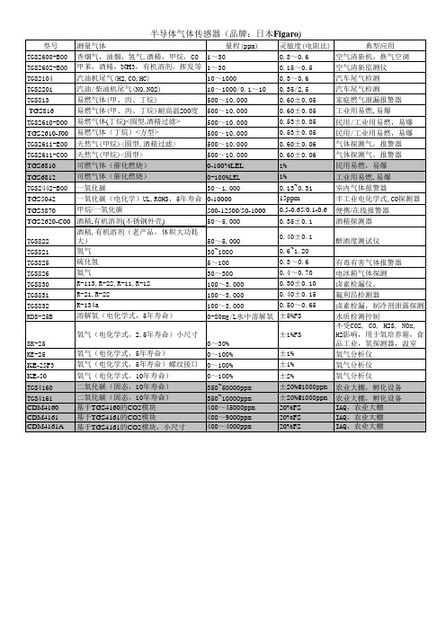
型号 TGS2600-B00 TGS2602-B00 TGS2104 TGS2201 TGS813 TGS816 TGS2610-DOO TGS2610-J00 TGS2611-E00 TGS2611-C00 TGS6810 TGS6812 TGS2442-B00 TGS5042 TGS3870 测量气体 量程(ppm) 香烟气,油烟,氢气,酒精,甲烷,CO 1~30 甲苯,酒精,NH3,有机溶剂,挥发等 1~30 汽油机尾气(H2,CO,HC) 10~1000 汽油/柴油机尾气(NO,NO2) 10~1000/0.1~10 易燃气体(甲、丙、丁烷) 500~10,000 易燃气体(甲、丙、丁烷)耐高温200度 500~10,000 易燃气体(丁烷)<圆型,酒精过滤> 500~10,000 易燃气体(丁烷)<方型> 500~10,000 天然气(甲烷)<圆型,酒精过滤> 天然气(甲烷)<圆型> 可燃气体(催化燃烧) 可燃气体(催化燃烧) 一氧化碳 一氧化碳(电化学)UL,ROHS,5年寿命 甲烷/一氧化碳 500~10,000 500~10,000 0-100%LEL 0-100%LEL 30~1,000 0-10000 500-12500/50-1000 50~5,000 50~5,000 30~1000 5~100 30~300 100~3,000 100~3,000 100~3,000 0-80mg/L水中溶解氧 灵敏度(电阻比) 0.3~0.6 0.15~0.5 0.3~0.6 0.35/2.5 0.60±0.05 0.60±0.05 0.53±0.05 0.53±0.05 0.60±0.06 0.60±0.06 1% 1% 0.13~0.31 15ppm 0.5-0.65/0.1-0.6 0.35±0.1 0.40±0.1 0.6~1.20 0.3~0.6 0.4~0.70 0.30±0.10 0.40±0.15 0.50~0.65 ±5%FS ±1%FS 0~30% 0~100% 0~100% 0~100% 350~50000ppm 350~10000ppm 400~45000ppm 400~9000ppm 400~4000ppm ±1% ±1% ±2% ±20%@1000ppm ±20%@1000ppm 20%FS 20%FS 20%FS 典型应用 空气清新机,换气空调 空气清新监测仪 汽车尾气检测 汽车尾气检测 家庭燃气泄漏报警器 工业用易燃, 易爆 民用/工业用易燃,易爆 民用/工业用易燃,易爆 气体探测气,报警器 气体探测气,报警器 民用易燃,易爆 工业用易燃, 易爆 室内气体报警器 半工业电化学式,CO探测器 便携/在线报警器 酒精探测器 醉酒度测试仪 有毒有害气体报警器 电冰箱气体探测 卤素检漏仪, 氟利昂检测器 卤素检漏,制冷剂泄露探测 水质检测控制 不受CO2, CO, H2S, NOx, H2影响,用于氧培养箱,食 品工业,氧探测器,温室 氧气分析仪 氧气分析仪 氧气分析仪 农业大棚,孵化设备 农业大棚,孵化设备 IAQ,农业大棚 IAQ,农业大棚 IAQ,农业大棚
空气质量传感器TGS2600在空气质量监测中的应用
空气质量传感器TGS2600在空气质量监测中的应用引言近年来,空气质量监测越来越受到人们的重视,国内外的众多企业与研究机构在气体传感器研发领域取得了长足进步,目前气体传感器正向集成化、智能化、多参数检测的方向迅速发展。
日本FIGARO公司开发生产的系列半导体气体传感器代表了目前气体传感器领域最新的水平,为研究开发空气质量监测系统创造了有利条件,提供了一条简单而实用的途径。
1 半导体气敏传感器及其特性半导体气敏传感器是利用待测气体与半导体(主要是金属氧化物)表面接触时,产生的电导率等物性变化来检测气体。
半导体气敏器件被加热到稳定状态下,当气体接触器件表面而被吸附时,吸附分子首先在表面自由地扩散(物理吸附),失去其运动能量,其间的一部分分子蒸发,残留分子产生热分解而固定在吸附处(化学吸附)。
这时,如果器件的功函数小于吸附分子的电子亲和力,则吸附分子将从器件夺取电子而变成负离子吸附。
具有负离子吸附倾向的气体最典型的是O2,称为氧化型气体或电子接收性气体。
如果器件的功函数大于吸附分子的离解能,吸附分子将向器件释放电子,而成为正离子吸附。
具有这种正离子吸附倾向的气体有H2、CO、碳氢化合物和酒类等,称为还原型气体或电子供给性气体。
目前可用于检测气体的敏感元件有很多种,如SnO2,ZnO,Fe2O3和气敏元件等。
它们共同的特点是可以检测多种不同的气体,但对气体的选择性较差。
这种非单一选择性是由其敏感机理所决定的,虽然可以采用添加适量的贵重金属Pt、Pd等方法改善其选择性,但仍然会对其它气体有一定的敏感度。
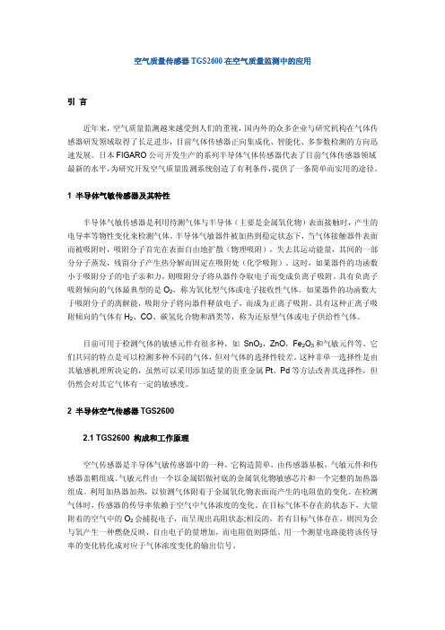
2 半导体空气传感器TGS26002.1 TGS2600 构成和工作原理空气传感器是半导体气敏传感器中的一种,它构造简单,由传感器基板,气敏元件和传感器盖帽组成。
气敏元件由一个以金属铝做衬底的金属氧化物敏感芯片和一个完整的加热器组成。
利用加热器加热,以侦测气体附着于金属氧化物表面而产生的电阻值的变化。
在检测气体时,传感器的传导率依赖于空气中气体浓度的变化。
空气质量传感器(异味传感器)TGS2600应用资料
1—30ppm H2
5.0±0.2VDC/AC(直/交流)
5.0±0.2 Ps≤15mW
V DC
变量
≥0.45kΩ
室温条件下大约 83 Ω
42±4mA
210mW VH=5.0V DC
10K-90 kΩ在空气中
0.3-0.6
RS (10 ppm,氢气) RS (空气)
在20±2°C, 65±5%RH的正常空气
TGS2600 —空气质量检测
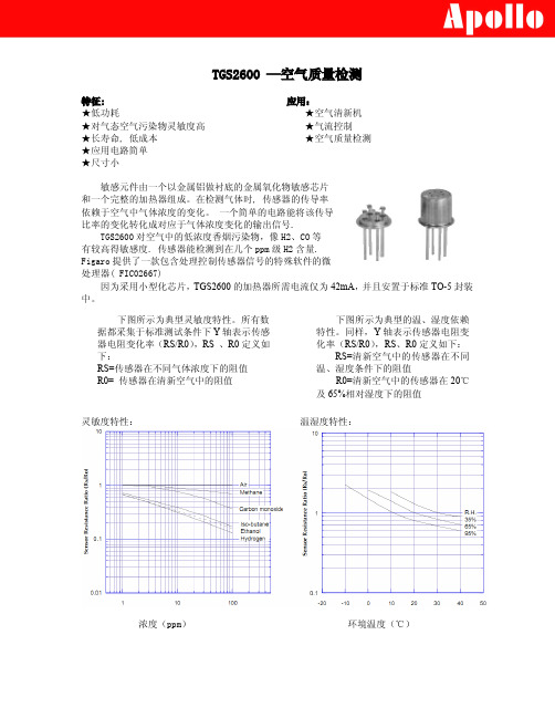
特征: ★低功耗 ★对气态空气污染物灵敏度高 ★长寿命, 低成本 ★应用电路简单 ★尺寸小
应用: ★空气清新机 ★气流控制 ★空气质量检测
敏感元件由一个以金属铝做衬底的金属氧化物敏感芯片 和一个完整的加热器组成。在检测气体时, 传感器的传导率 依赖于空气中气体浓度的变化。 一个简单的电路能将该传导 比率的变化转化成对应于气体浓度变化的输出信号.
RS=清新空气中的传感器在不同 温、湿度条件下的阻值
R0=清新空气中的传感器在 20℃ 及 65%相对湿度下的阻值
灵敏度特性:
温湿度特性:
浓度(ppm)
环境温度(℃)
基本测量电路: 此传感器要求有两个电压输入:加热器电压 VH
和线路电压 VC。加热器电压 VH 加于集成加热器上 以保持传感器在一个特定的最佳感应温度。电路电压 VC 被加载以便于测量与感应元件串联的负载电阻电压 Vout。此传感器有极性所以电路电压 VC 必须是直流。 可以用一个公共的电源来同时供给 VH 和 VC 以满足传 感器的电气需求。负载电阻 RL 的选择要使报警门限电 压最优化,并使半导体器件的功耗小于 15mw。当目标 气体存在时,传感器功耗在 RS 与 RL 相等时最大。
VC = 5.0±0.01V DC VH = 5.0±0.05V DC
日本费加罗Figaro氧气传感器

日本费加罗Figaro氧气传感器广州南创陈工FIGARO是一家专业生产半导体气体传感器的公司,1962年发明全球第一款半导体产品,目前全球第一。
FIGARO的产品远销38个国家,在多个国家设立了分支机构或办事处,生产基地遍布美洲、东欧、中国等地;并在中国设立了广州南创传感器事业部,可为用户的实验和生产提供最佳的服务与解决方案。
半导体气体传感器采用金属氧化物半导体烧结工艺,对被检测的检测气体具有灵敏度高、响应时间短、成本低、长期稳定性好等优点。
我们的产品包括可燃气体、有毒气体、空气质量、一氧化碳、二氧化碳、氨气、汽车尾气、酒精等传感器元件、传感模块等,以及各种气体传感器的配套产品。
目前已经被广泛应用于家用燃气报警器、工业有毒气体报警器、空气清新机、换气空调、空气质量控制、汽车尾气检测、蔬菜大棚、酒精检测、孵化机械等。
日本费加罗Figaro氧气传感器KE-25KE-50信息日本费加罗Figaro氧气传感器KE-25KE-50性能:测量范围:0-100%O2精度:氧气传感器KE-25:±1%(全量程);氧气传感器KE-50:±2%(全量程)工作温度:5~40℃储存温度:-20~+60℃响应时间:KE-25:14±2秒;KE-50:60±5秒初始输出:KE-25:10.0–15.5mv;KE-50:47.0-65.0mv期望寿命:KE-25:5年;KE-50:10年日本费加罗Figaro氧气传感器KE-25KE-50特性:长寿命(KE-25-5年,KE-50-10年)不受CO2,CO,H2S,NOx,H2影响低成本,在常温下工作信号输出定,无需外部电源不需加热以上日本费加罗Figaro氧气传感器技术参数以《OIML60号国际建议》92年版为基础,最新具体变化可查看《JJG669—12FIGARO广州南创传感器事业部检定规程》产品特性描述:氧气传感器KE-25KE-50属于半导体气体传感器不受CO2,CO,H2S,NOx,H2影响,氧气传感器KE-25KE-50低成本在常温下工作信号输出定,无需外部电源不需加热;精度氧气传。
日本费加罗FIGARO TGS5042民用一氧化碳传感器

Technical Information for Carbon Monoxide SensorsF igaro’s TGS5042 is a battery operable electrochemical sensor which offers several advantages over traditional electrochemical sensors. Its electrolyte is environmentally friendly, it poses no risk of electrolyte leakage, can detect concentrations as high as 1% CO, operates in a range from -5˚ and +55˚C, and it has lower sensitivity to interference gases. With a long life, good long term stability, and high accuracy, this sensor is the ideal choice for CO detectors with digital display. OEM customers will find individual sensors data printed on each sensor in bar code from, enabling users to skip the costly gas calibration process and allowing for individual sensor tracking. TGS5042 utilizes a standard AA battery-sized package.S p e c i f i c a t i o n s P a g e Features..................................................................................................2 Applications...............................................................................................2 Structure...........................................................................................2 Basic Measuring Circuit...........................................................................2 Operating Conditions & Specifications...................................................3 Mechanical Strength..............................................................................3 Dimensions...................................................................................................3Operation Principle ......................................................................................................4Basic Sensitivity Characteristics Sensitivity to Various Gases............................................................5 Temperature and Humidity Dependency.............................................5 Gas Response Pattern.................................................................................6 Repeatability.............................................................................6 Influence of Storage...................................................................................6 Normal Operation Test.....................................................................................7 Sensitivity Test...................................................................................7Reliability Interference Gas Test......................................................................................8 Long-Term Stability................................................................................9 Corrosion Test...........................................................................................9 Variable Ambient Temperature Test................................................................9 Humidity Test.............................................................................................10 Stability Tests..................................................................................................11 Sequential Test...........................................................................................11 Dust Test................................................................................................12 Water Loss Test.......................................................................................12Marking ..........................................................................................................................12Cautions .......................................................................................................13Appendix . (14)a n I S O 9001 c o m p a n yIMPORTANT NOTE: OPERATING CONDITIONS IN WHICH FIGARO SENSORS ARE USED WILL VARY WITH EACH CUSTOMER’S SPECIFIC APPLICATIONS. FIGARO STRONGLY RECOMMENDS CONSULT-ING OUR TECHNICAL STAFF BEFORE DEPLOYING FIGARO SENSORS IN YOUR APPLICATION AND, IN PARTICULAR, WHEN CUSTOMER’S TARGET GASES ARE NOT LISTED HEREIN. FIGARO CANNOT ASSUME ANY RESPONSIBILITY FOR ANY USE OF ITS SENSORS IN A PRODUCT OR APPLICATION FORWHICH SENSOR HAS NOT BEEN SPECIFICALLY TESTED BY FIGARO.TGS5042 is a UL recognized component in accordance with the requirements of UL2034. Please note that component recognition testing has confirmed long term stability in 15ppm of carbon monoxide; other characteristics shown in this brochure have not been confirmed by UL as part of component recognition.1. Specifications1-1 Features* Battery operable* High repeatability/selectivity to carbon monoxide * Linear relationship between CO gas concentration and sensor output* Simple calibration* Long life* UL recognized component* Meets UL2034, EN50291, and RoHS requirements 1-2 Applications* Residential and commercial CO detectors* CO monitors for industrial applications* Ventilation control for indoor parking garages* Fire detection1-3 StructureFigure 1 shows the structure of TGS5042. The gas sensing layer is sandwiched between a stainless steel washer (counter electrode) and a stainless steel cap (working electrode), together with gas diffusion control stainless film and backing layers. This assembly is placed in the compartment of the stainless steel can. Water is stored in the bottom compartment and a charcoal filter is installed inside the stainless steel cap.1-4 Basic measuring circuitF igure 2 shows the basic measuring circuit of TGS5042. The sensor generates a minute electric current which is converted into sensor output voltage (Vout) by an op-amp/ resistor (R1) combination.Figaro recommends the following electrical parts:R1 : 1MΩC1 : 1µFIC : AD708An additional resistor or F ET is required to prevent polarization of the sensor when circuit voltage is off. NOTE: When voltage is applied to the sensor output terminal, the sensor may be damaged. Voltage applied to the sensor should be strictly limited to less than ±10mV.1-5 Operating conditions & specifications (Table 1)Figure 1 - Sensor structureFigure 2 - Basic measuring circuit(Including equivalent circuit)Cap /Working electrodeVoutNOTE 1: Sensor output in air under operating conditionsNOTE 2:If the water in the reservoir should freeze very rapidly (typically occurs only under artifically created conditions), irreversible change to sensor characteristics would occur. To avoid this risk, the sensor is recommended to be positioned with its cap (working electrode) facing up. NOTE 3: Please contact Figaro for more information if the required temperature range would exceed the specified limits.Table 1 - Operating conditions and specifications1-6 Mechanical strengthThe sensor shall have no abnormal findings in its structure and shall satisfy the above electrical specifications after the following performance tests: Withstand force -withstand force of 10kg (cap from metal can) along a vertical axisVibration - frequency--10~500Hz (equiv. to 10G), duration - 6 hours, x-y-z directionShock - acceleration-100G, repeat 5 times 1-7 Dimensions (see Fig. 3)Figure 3 - DimensionsAll sensor characteristics shown in this brochu re represent typical characteristics. Actu al characteristics vary from sensor to sensor and from production lot to production lot. The only characteristics warranted are those shown in the Specification.NOTE: The sensor can be supplied with lead pins. Please refer to the Appendix for detailsTop viewBottom viewSide view2. Operation PrincipleThe electrolyte of TGS5042 is a very low concentra-tion of mixed/prepared alkaline electrolyteconsisting of KOH, KHCO 3, and K 2CO 3. Themixed alkaline electrolyte acts as a buffer solution with a pH value maintained between 7~10. When CO passes through the backing layer and reaches to the working electrode, electrons are generated resulting from the reaction between CO and anionsin the electrolyte such as OH -, HCO 3-, and CO 32-(see equations 1a~1c ). By creating a short circuitbetween the working and counter electrodes with external wiring, electrons move to the counter electrode through the external wiring. At that point, the consumed anions in the electrolyte at the working electrode are replenished and move to the electrolyte by the reaction of CO 2, water, and electrons as shown in equations 2a~2c. The total reaction is expressed as shown in equation 3.A linear relationship exists between the sensor'selectric current and CO concentration (see equation 4). By calibrating the sensor with a known concentration of CO gas, the output current of the sensor can then be used to quantitatively determine CO concentration.Since, unlike conventional dry batteries, there is no consumption of active materials or of the electrodes, TGS5042 possesses excellent long-term stability for its output signal and enables maintenance-free operation. Furthermore, the sensor's self-generating output current makes it ideal for usage in battery-operated CO detectors.Figure 4 - Operation principleFigure 5 - Schematic diagram of TGS5042operating principleSeparator immersed in liquid alkaline electrolyteWorking electrode (Anodic reaction)CO + 2OH - → CO 2 + H 2O + 2e - (equation 1a )CO + 2HCO 3- → 3CO 2 + H 2O + 2e - (equation 1b )CO + CO 32- → 2CO 2 + 2e - (equation 1c )Counter electrode (Cathodic reaction)1/2O 2 + H 2O + 2e - → 2OH - (equation 2a ) 1/2O 2 + 2CO 2 + H 2O + 2e - → 2HCO 3- (equation 2b ) 1/2O 2 + CO 2 + 2e - → CO 32- (equation 2c )Total reactionCO + 1/2 O 2 → CO 2 (equation 3)Theoretical output current valueI = F x (A/σ) x D x C x n (equation 4) where :F : Faraday constant A: Surface area of diffusion filmD: Gas diffusion co-efficient C: Gas concentration σ: Thickness of diffusion filmn: Number of reaction electrons深圳市深国安电子科技有限公司3. Basic Sensitivity Characteristics 3-1 Sensitivity to various gasesF igure 6 shows the sensor’s sensitivity to various gases. The Y-axis shows output current (Iout/µA) in each gas. The output current is linear to CO concen-tration, with a deviation of less than ±5% in the range of 0~500ppm. Cross sensitivity data for other gases than those in Figure 6 are tabulated in Table Y.3-2 Temperature and humidity dependencyF igure 7a shows the temperature dependency of TGS5042 under a constant humidity of 50%RH. The Y-axis shows the ratio of output current in 400ppm of CO at various temperatures (I) to the output current in 400ppm of CO at 20˚C/50%RH (Io). Temperature dependency is based on the difference in the catalytic reaction rate on the electrodes, and it can be simply compensated by utilizing a thermistor. This linear relationship between I/Io and CO concentration is constant regardless of CO concentration range, according to the sensor's operating principle.F igure 7b shows the humidity dependency of TGS5042 under constant temperatures of 20˚C and 50˚C. The Y-axis shows the ratio of output current in 400ppm of CO at various relative humidities (I) to the output current in 400ppm of CO at 20˚C/50%RH (Io). This data demonstrates that humidity dependency is negligible as temperature varies.Figure 6 - Sensitivity to various gasesFigure 7a - Temperature dependency at 400ppm CO/50%RH(Io=sensor output current at 20˚C)Figure 7b - Humidity dependency at 400ppm CO(Io=sensor output current at 50%RH)0.00.51.01.52.020406080100Relative Humidity (%)Note : The figures in this table are typical values and should not be used as a basis for cross calibration. Cross sensitivity for various gases may not be linear and should not be scaled. All data based on a 4 minute exposure. For some gases, filter saturation and gas breakthrough mayoccur if gas is applied for a longer time period.0.00.51.01.52.0-10102030405060Temperature (˚C)3-3 Gas response patternF igure 8 shows the gas response pattern of the output signal when the sensor is placed into 30, 70, 150 and 400ppm of CO and then returned to normal air. The response time to 90% of the saturated signal level is within 60 seconds, and the recovery of the signal back to 90% of the base level is within 120 seconds. This data demonstrates that TGS5042 possesses sufficient response speed for meeting UL requirements for CO detectors.3-4 RepeatabilityF igure 9 shows the pattern of the output signal when the sensor is repeatedly exposed to 400ppm of CO at a constant interval of 240 seconds. The data demonstrates extremely high reproducibility of the output signal, the deviation being less than ±5%.3-5 Influence of storageF igure 10 shows the initial action of the sensor's output current signal in fresh air. F or the purpose of this test, sensors were stored for more than six months under two separate conditions between the working and counter electrodes: in short-circuited condition, and in open-circuited condition. The chart illustrates the behavior of sensor output current for each group just after installation into the operating circuit. The output current signal of sensors stored in a short-circuited condition reaches its saturated level quickly, while those stored with an open-circuit exhibit much slower behavior. Since sensors are shipped in an open-circuit condition, stabilization time of one hour (typical) is recommended. If an anti-polarization circuit is used (see Item 2-5 in Application Notes for TGS5042), placing the sensor onto the pcb for one hour should be sufficient to stabilize the output. If no anti-polarization circuit is used, placing the sensor into the detector circuit and powering the circuit for about one hour should be sufficient to stabilize sensor output.Figure 8 - Response patternFigure 9 - Repeatability (in 400ppm of CO)0.00.20.40.60.81.00500100015002000Time (sec.)-0.20.00.20.40.60.81.00500100015002000Time (sec.)Figure 10 - Influence of storage(in fresh air)Figure 11a shows the result of the “Normal Operation Test” required by UL2034, Sec. 35.3 where the sensor is exposed to 600ppm of CO for 12 hours at 20˚C/40%RH. Stable output current signal can be seen throughout the exposure.In addition, F igure 11b shows the CO sensitivity characteristics of the sensor before, during, and after the Normal Operation Test, demonstrating that TGS5042 is hardly influenced by exposure to high concentrations of CO.3-7 Sensitivity testFigure 12a shows the results of the “Sensitivity Test” as required by UL2034, Sec. 38. Under this test, the sensor was exposed to 30, 70, 150 and 400ppm of CO at 20˚C/40%RH. The period of exposure was varied by concentration, corresponding with the maximum time in which a CO detector should generate an alarm for the subject concentration. Throughout the test exposures, TGS5042 displayed a reasonable and stable output current signal.Figure 11a - Normal operation test (CO 600±30ppm for 12 hours at 20˚C/40%RH) 0.00.51.01.5Figure 11b - Normal operation test(20˚C/40%RH)0.20.40.60.81Figure 12a - Sensitivity test(20˚C/40%RH)In addition, Figure 12b indicates the CO sensitivity characteristics of the sensor before, during, and after the Sensitivity Test, demonstrating the excellent reproducibility of TGS5042's CO sensitiv-ity characteristics.4. ReliabilityT ests conducted in this section demonstrate that TGS5042 can meet the requirements of various testing standards without incurring adverse long term effects from such tests.4-1 Interference gas testFigure 13a shows the results of testing the TGS5042 sensor for durability against various interference gases as specified by UL2034, Sec. 39. The test was conducted by exposing the sensor to each gas shown in Figure 13a (starting with CO 30ppm) for two hours, then removing the sensor to fresh air for just one hour, and followed by inserting the sensor into the next gas. This procedure was repeated for the full range of gases shown in Figure 13a. Because the sensor is exposed to each of the test gases consecutively, to some small extent the effect of the previous test gas may affect subsequent tests for a short period. However, despite the short-term effects of such gases remaining after exposure, the sensor still shows significantly less sensitivity to each test gas when compared to 30ppm of CO, and CO sensitivity remains unaffected.In addition, F igure 13b shows the CO sensitivity characteristics of the sensor before and after this test, further demonstrating the excellent reproducibility of the CO sensitivity characteristics of TGS5042, demonstrating its durability against the interference gases listed in the requirements of UL2034, Sec. 39.Fig. 12b - Sensitivity test(20˚C/40%RH)Figure 13a - Interference gas test(20˚C/40%RH)-0.020.020.040.060.08AC O30p pM et h an e500ppB ut a ne300p pH ep t an e500ppE th yl ac et a te200p pI P A200ppC O25000ppN H3100p pE th an ol200p pT ol u en e200ppT ri c hl o ro et h an e200ppA ce t on e200ppC O30p p AFigure 13b - Interference gas test(20˚C/40%RH)深圳市深国安电子科技有限公司4-2 Long-term stabilityigure 14 shows long-term stability data for TGS5042. Test samples were stored in natural clean air under a short-circuit condition and measured at various intervals as dictated by the standard test conditions of UL2034, Sec. 38. The Y-axis shows the ratio of output current in 300ppm of CO at any point in time (I) over output current in 300ppm of CO on the first day of the test (Io). This chart demonstrates very stable characteristics with a variation of less than ±15% for more than 7 years.4-3 Corrosion testTo demonstrate the durability of TGS5042 against corrosion, samples were subjected to test conditions called for by UL2034, Sec.58-Corrosion Test. Over a three-week period, a mixture of 100ppb of H2S, 20ppb of Cl2, and 200ppb of NO2 was supplied to the sensors at a rate sufficient to achieve an air exchange rate of five times per hour. Figure 15 shows the CO sensitivity characteristics before and after exposure in the above conditions, demonstrating that TGS5042 is hardly influenced by such corrosive gases. In addition, the sensor's stainless steel housing did not show any sign of corrosion as a result of this test.4-4 Variable ambient temperature testTo demonstrate the ability of TGS5042 to withstand the effects of high and low temperature, the “Variable Ambient Temperature Test” of UL2034, Sec. 45 was conducted.(1) Operation in high and low temperature test Figure 16a shows the results for the “Operation in High and Low Temperature Test” of UL2034, Sec.45.1. The sensor was exposed to environments of 0˚C/15%RH and 49˚C/40%RH for at least three hours each, with measurements taken before and during the exposure in accordance with the test conditions of UL2034, Sec. 38. By plotting the output current values from these test measurements atop the data taken prior to this test at a constant 50%RH (representing standard temperature dependency), it can be seen that the test data are still in line with data taken at a constant RH. The conclusion which can be drawn is that, regardless of exposure to extremes of temperature and humidity, the sensor's output is not affected by humidity. As a result, TGS5042 can meet the requirements of UL2034, Sec. 45.1 by utilizing a simple temperature compensation method.Figure 14 - Long term stabilityFigure 15 - Durability against corrosionFigure 16a - Operation in high and low temperature (all data at 50%RH except Sec. 45.1 test points) 0.00.51.01.52.02.53.0Time (days)(2) Effect of shipping and storageTo verify the effects of shipping and storage, the sensor was tested under the conditions of UL2034, Sec. 45.2. Test samples in a short-circuited condition were subjected to 70˚C for 24 hours, allowed to cool to room temperature for 1 hour, subjected to -40˚C for 3 hours, and then allowed to warm up to room temperature for 3 hours. Figure 16b shows the CO sensitivity characteristics before and after the test, demonstrating that TGS5042 meets the requirement of UL2034, Sec. 45.2.4-5 Humidity testF igure 17a shows the results of testing the sensor under UL2034, Sec. 46A. The sensor was exposed in an atmosphere of 52±3˚C/95±4%RH for a period of 168 hours, returned to normal air for 2 days, then followed by 168 hours exposure at 22±3˚C/10±3%RH. The data demonstrates the stable characteristics in both low and high humidity conditions.Figure 17b shows data taken prior to the above test at a constant relative humidity of 50%. These curves represent the typical temperature dependency of the sensor. When plotting measurements taken at the environmental extremes specified on UL2034, Sec. 46A (52±3˚C/95±4%RH and 22±3˚C/10±3%RH) onto the temperature dependency curves, it can be seen that measurements taken at these extreme conditions still fall in line with the temperature dependency curve derived prior to testing. The conclusion which can be drawn is that, regardless of exposure to extremes of temperature and humidity, the sensor's output is not affected by humidity. As a result, TGS5042 can meet the requirements of UL2034, Sec. 46A by utilizing a simple temperature compensation method.Figure 16b - Effects of shipping and storageFigure 17a - Humidity testFigure 17b - Humidity test(all data at 50%RH except Sec. 46A test points))4-6 Stability test(1) False alarm testTo show the sensor’s behavior under continuous low level exposure to CO, samples were tested against the procedure detailed in UL2034, Sec.41.1(c)-Stability Test. Test samples were exposed to 30ppm of CO continuously for a period of 30 days under standard circuit conditions. Figure 18 shows the CO sensitivity characteristics before and after the exposure test, demonstrating that detectors using TGS5042 will not give a false alarm as a result of continuous low level CO exposure.(2) Temperature cycle testIn accordance with UL2034, Sec. 41.1(e)-Stability Test, test samples were exposed to ten cycles (<1 hour and >15 minutes) of temperature from 0˚C/100%RH to 49˚C/40%RH. F igure 19 shows CO sensitivity characteristics before and after the cycle test, demonstrating that TGS5042 is hardly influenced by the extreme conditions of the temperature cycle test.4-7 Sequential testIn UL2034, Sec. 41.3, a single lot of sample detectors are to be subjected to the following sequence of tests: Section 38, Section 41.1, Section 39, Section 45, and Section 46A. While TGS5042 meets the requirements of each of these test individually (as shown elsewhere in this brochure), this test is designed to demonstrate the sensor's ability to withstand all of these test when conducted in sequence. Figure 20 shows the results of sequentially testing the same lot of sensors. The good stability of the sensor's output signal indicates that TGS5042 can satisfy the requirements of UL2034, Sec. 41.3-Sequential Test.Figure 18 - False alarm testFigure 19 - Temperature cycle testB ef o re te st i ngA ft e rS ec.38t e stA ft e rS ec.41.1t e stA ft e rS ec.39t e stB ef o re Se c.45.1v ar.am bi e nt t em pt e stA ft e rS ec.45.1v ar.am bi e nt t em pt e st(0˚C)A ft e rS ec.45.1v ar.am bi e nt t em pt e st(49˚C)B ef o re Se c.45.2s hi p pi n g/s to r ag et e stA ft e rS ec.45.2s hi p pi n g/s to r ag et e st(-40˚C)A ft e rS ec.45.2s hi p pi n g/s to r ag et e st(70˚C)B ef o re Se c.46Ah i gh hu mi d it yt e st t es tA ft e rS ec.46A hi g hh um id i ty te st t es tA ft e rS ec.46A lo wh um id i ty te st t es tA ft e rs eq ue nt i al t es tA ft e rS ec.35.3t e stFigure 20 - Sequential test4-8 Dust testTo judge the effect of dust contamination on TGS5042, approximately 2 ounces (0.06 kg) of cement dust, capable of passing through a 200 mesh screen, was circulated for 1 hour by means of a blower, enveloping the sensor in the test chamber. Air flow was maintained at an air velocity of approximately 50 fpm (0.25 m/s) at 20˚C/40%RH. Figure 21 shows the sensor's CO sensitivity characteristics before and after the dust exposure test. This data demonstrates that the dust test of UL2034, Sec. 53 has a negligible effect on CO sensitivity.4-9 Water loss testF or evaluating the life expectancy of TGS5042 from the viewpoint of its water reservoir (which prevents the electrolyte from drying up), the weight loss of TGS5042 was periodically measured when stored at 20˚C/40%RH and 70˚C/5%RH respectively. F igure 22 demonstrates that the sensor’s weight decreased linearly with time due to evaporation of the water. The rate of water loss under various temperature was related with the water vapor pressure at each temperature. According to calculations based on this rate of water loss and the differences in water vapor pressure in 20˚C and 70˚C, the water (>4.5g initially) will last more than 10 years under natural residential conditions such as 20˚C/40%RH.5. MarkingThe TGS5042 comes with a sticker attached to the sensor housing which contains important information. The one dimensional bar code indicates the sensor's sensitivity (slope) in numeric value as determined by measuring the sensor's output in 300ppm of CO:xxxx = x.xxx nA/ppmIn user readable format, the sensor's sensitivity per ppm (nA) is printed below the one dimensional bar code and the sensor's Lot Number is printed to the left of the sensitivity data. Please note that three decimal places should be added to the sensitivity reading (e.g. 1827 should be read as 1.827 nA/ppm).-0.10-0.08-0.06-0.04-0.020.00020*********Time (days)Figure 22 - Water loss testFigure 21 - Dust test1827Sensitivity to CO (nA/ppm)FIGAROTGS5042(Ex.1827 = 1.827nA/ ppm)Figure 23 - TGS5042 markings(NOTE:UL Mark may appear on shrink tube)6. Cautions6-1 Situations which must be avoided1) Disassembling the sensorUnder no circumstances should the sensor be disassem-bled, nor should the sensor can and/or cap be deformed.2) Contamination by alkaline metalsSensor characteristics may be significantly changed when the sensor is contaminated by alkaline metals, especially salt water spray.3) Exposure to high concentration of basic (non-acidic) gases Sensor characteristics may be irreversibly changed by the exposure to high concentrations of basic gases such as ammonia.4) High temperature exposureAt temperatures of 80˚C or higher, the sensing membrane may deteriorate, resulting in irreversible change of sensor characteristics.5) Contact with waterSensor characteristics may be changed due to soaking or splashing the sensor with water.6) Application of excessive voltageIf higher than specified voltage is applied to the sensor, breakage may occur or sensor characteristics may drift, even if no physical damage or breakage occurs. Do not use the sensor once excessive voltage is applied.6-2 Situations to avoid whenever possible1) Exposure to silicone vaporsAvoid exposure of sensor where silicone adhesives, hair grooming materials, or silicone rubber/putty may be present. Silicone vapors may cause clogging of the gas diffusion route.2) Dew condensationIf severe dew condensation occurs for a long period inside of the sensor or on the sensor surface, it may cause clogging of gas diffusion route or deterioration of the sensing membrane. Mild dew condensation which occurs in normal indoor air would not cause any significant damage.3) Storage in sealed containerDo not keep the sensor in a sealed containers such as sealed bag. Due to ambient temperature change, dew condensation may occur inside the sensor if the sensor is stored in this manner.4) FreezingWhen subjected to temperatures below 0˚C, it is possible that the water in the reservoir may freeze. Since water volume will expand when freezing, the sensor can may undergo some deformation. Care should be taken in the design of the detector to ensure that the sensor is not placed too close to other components or the circuit pattern on a PCB, as such deformation may cause the sensor to come in contact with these items. In addition, if the freezing process were to occur very rapidly, the sensor will undergo irreversible change in its characteristics. To avoid this risk, it is recommended that the sensor be positioned with the cap (working electrode) facing up (for more information, refer to Item 3-1 Position Dependency of the Sensor in the document Application Notes for TGS5042).5) Exposure to hydrogen sulfide or sulfuric acid gasIf the sensor is exposed to hydrogen sulfide or sulfuric acid gas, sensor components such as the gas diffusion film, can, and cap may be corroded, resulting in the sensor damage.6) Vibration and shockVibration and shock may cause an open or short circuit inside the sensor.7) Dust and oil mistExtremely high concentrations of dust or oil mist may cause clogging of the sensor's internal structure. When such conditions are expected to be encountered, installation of an external air filter is recommended.8) Flux for solderingManual soldering is recommended since high concen-trations of flux may affect sensor characteristics when the sensor is soldered by wave soldering. When wave soldering is used, a test should be conducted before production starts to see if there would be any influence to sensor characteristics. Please refer to Item 5-3 of Application Notes for TGS5042 for advice on manual soldering conditions. 9) Exposure to organic vaporsIf the sensor is exposed to organic vapors such as alcohols, acetone, or volatile oils, these gases may adsorb on the sensor surface, resulting in temporary sensor drift.6-3 Additional cautions for installationThis sensor requires the existence of oxygen in the operating environment to function properly and to exhibit the characteristics described in this brochure. The sensor will not operate properly in a zero oxygen environment. Figaro USA Inc. and the manufacturer, Figaro Engineering Inc. (together referred to as Figaro) reserve the right to makechanges without notice to any products herein to improve reliability, functioning or design. Information contained in this document is believed to be reliable. However, Figaro does not assume any liability arising out of the application or use of any product or circuit described herein; neither does it convey any license under its patent rights, nor the rights of others.F igaro's products are not authorized for use as critical components in life support applications wherein a failure or malfunction of the products may result in injury or threat to life.。
日本Figaro传感器

日本Figaro传感器广州南创陈工FIGARO是一家专业生产半导体气体传感器的公司,1962年发明全球第一款半导体产品,目前全球第一。
FIGARO的产品远销38个国家,在多个国家设立了分支机构或办事处,生产基地遍布美洲、东欧、中国等地;并在中国设立了广州南创传感器事业部,可为用户的实验和生产提供最佳的服务与解决方案。
半导体气体传感器采用金属氧化物半导体烧结工艺,对被检测的检测气体具有灵敏度高、响应时间短、成本低、长期稳定性好等优点。
我们的产品包括可燃气体、有毒气体、空气质量、一氧化碳、二氧化碳、氨气、汽车尾气、酒精等传感器元件、传感模块等,以及各种气体传感器的配套产品。
目前已经被广泛应用于家用燃气报警器、工业有毒气体报警器、空气清新机、换气空调、空气质量控制、汽车尾气检测、蔬菜大棚、酒精检测、孵化机械等。
日本Figaro传感器KE-25 KE-50信息日本Figaro传感器KE-25 KE-50性能:测量范围:0-100%O2精度:氧气传感器KE-25:±1%(全量程);氧气传感器KE-50:±2%(全量程)工作温度:5~40℃储存温度:-20~+60℃响应时间:KE-25:14±2秒;KE-50:60±5秒初始输出:KE-25:10.0–15.5mv;KE-50:47.0-65.0mv期望寿命:KE-25:5年;KE-50:10年日本Figaro传感器KE-25 KE-50特性:长寿命(KE-25-5年,KE-50-10年)不受CO2,CO,H2S,NOx,H2影响低成本,在常温下工作信号输出定,无需外部电源不需加热以上日本Figaro传感器技术参数以《OIML60号国际建议》92年版为基础,最新具体变化可查看《JJG669—12FIGARO广州南创传感器事业部检定规程》产品特性描述:氧气传感器KE-25 KE-50属于半导体气体传感器不受CO2,CO,H2S,NOx,H2影响,氧气传感器KE-25 KE-50低成本在常温下工作信号输出定,无需外部电源不需加热;精度氧气传感器KE-25:±1%(全量程);氧气传感器KE-50:±2%(全量程)。
日本FIGARO 费加罗KE-25氧气传感器5年寿命 KE-50长寿命10年氧气检测探头

Sensitivity characteristics (typical values under std.test conditions)Response time (typical)The GS Oxygen Sensor KE series (KE-25 and KE-50) is a unique galvanic cell type oxygen sensor which was developed in Japan in 1985. Its most notable features are long life expectency, excellent chemical durability, and it is not influenced by CO 2. The KE series oxygen sensor is ideal to meet the ever-increasing demand for oxygen monitoring in various fields such as combustion gas monitoring, the biochemical field, medical applications, domestic combustion appliances, etc.Features:* Long lifeKE-25 - 5 years / KE-50 - 10 years in ambient air * Virtually no influence from CO 2, CO, H 2S, NOx, H 2* Low cost* Operates in normal ambient temperatures * Stable output signal* No external power supply required for sensoroperation* No warmup time is requiredGS Oxygen SensorsApplications:* Medical - Anesthetic instruments, respirators,oxygen-enrichers* Biotechnology - Oxygen incubators* Food industry - Refrigeration, greenhouses* Safety - Air conditioners, oxygen detectors, firedetectorsREV: 08/03SpecificationsNotes:1) When calibrated at both 0% and 100% of O 2, accuracy in the range from 0-100% O 2 shall be within ±1% of full scale for KE-25 and ±2% of full scale for KE-50.2) Va = output voltage at 21% O 2 V 0 = output voltage at 0% O 2V 100 = output voltage at 100% O 23) Va = output voltage at 25˚C V H = output voltage at 40˚C V L = output voltage at 5˚C4) Sensors should be used under conditions where the air exchange is greater than 200~300ml per minute in order to obtain the response speed as specified in Table 1.22.7±0.5KE-25/KE-50 standard versionKE-25F1 (w/o flange)KE-25F3 (threaded top)KE-25F4 (O-ring top)22.7±0.522.7±0.5。
- 1、下载文档前请自行甄别文档内容的完整性,平台不提供额外的编辑、内容补充、找答案等附加服务。
- 2、"仅部分预览"的文档,不可在线预览部分如存在完整性等问题,可反馈申请退款(可完整预览的文档不适用该条件!)。
- 3、如文档侵犯您的权益,请联系客服反馈,我们会尽快为您处理(人工客服工作时间:9:00-18:30)。
TGS2602 用于空气污染物检测的气体传感器
* 对VOC 与气味有高灵敏度* 低功耗
* 对污染空气有高灵敏度* 使用寿命长* 应用电路简单* 体积小
特点:
应用:
敏感素子由集成的加热器以及在氧化铝基板上的金属氧化物半导体构成。
如果空气中存在对象检测气体,该气体的浓度越高传感器的电导率也会越高。
仅用简单的电路,就可以将电导率的变化转换成与该气体浓度相对应的信号输出。
TGS2602对低浓度气味的气体具有很高的灵敏度,这样还可以对办公室与家庭环境中的废弃物所产生的氨、硫化氢等气体进行检测。
该传感器还对木材精加工与建材产品中的VOC 挥发性气体如甲苯有很高的灵敏度。
由于实现了小型化,加热器电流仅需56mA ,外壳采用标准的TO-5金属封装。
下图所示为典型的灵敏度特性曲线,均在我公司的标准试验条件下(参见背面)测出。
纵坐标表示传感器电阻比 Rs/Ro ,Rs 与Ro 的定义如下:
Rs = 各种浓度气体中的传感器电阻值
下图所示为受温度、湿度影响的典型特性曲线。
纵坐标表示传感器电阻比 Rs/Ro ,Rs 与Ro 的定义如下:
Rs = 传感器在清洁空气中各种温/湿度下的电阻值Ro
= 传感器在清洁空气中, 温/湿度为20°C / 65% R.H.时的电阻值灵敏度特性:
温/湿度特性:
重要提示: 费加罗传感器的使用条件将因不同客户的具体运用不同而不同。
费加罗强烈建议在使用前咨询我们的技术人员,尤其是当客户的检测对象气体不在列表范围时,对于未经费加罗专业测试的任何使用,费加罗不承担任何责任。
* 空气清新机控制* 通风控制
* 空气质量监测* VOC 监视器* 气味监视器
R s /R o
R s /R o
规格:
结构以及尺寸:
管脚连接: 1: 加热器
2: 传感器电极 (-) 3: 传感器电极 (+) 4: 加热器
功耗值(P S )可通过下式求出:
传感器电阻(R S )可根据V OUT (V RL )的
测定值用下式求出:
(V C - V RL )2
R S
V C V RL
R S = (
- 1) x R L P S =
在此产品规格书中所显示的都是传感器的典型特性,实际的传感器特性因产品不同而不同,详情请参阅各传感器唯一对应的规格表。
: mm。