volvo重型卡车维修手册
Volvo Trucks EBR-VEB D11 系列产品说明书

Volvo Trucks. Driving Progress50100150200250300350400kWHoja de datosTipo de freno motor EBR-VEB+Freno motor - VEB+VEB+ (Volvo Engine Brake, freno motor de Volvo) es el sistema de fre nado de motor de alta e ficacia de Volvo. Se basa e n e l trabajo conjunto del regulador de la presión de gases de escape y e l fre no de compre sión por ape rtura de válvulas de e scape patentado de Volvo.La compre sión de ntro de los cilindros varía cuando actúa e l VEB+gracias a que el árbol de levas cuenta con un perfil especial para actuar sobre las válvulas de escape. La actuación del VEB+ tiene dos partes, una de contrapresión durante el ascenso del pistón en la fase de compresión, y otra de descompresión en el inicio del descenso del pistón en la fase de explosión (no hay inyección de combustible).Este siste ma ge ne ra una pote ncia de fre nado muy e le vada y suave en toda la gama de revoluciones. La diferencia del VEB+ sobre el VEB es que se ha añadido un balancín más para la función defreno motor, de forma que ahora hay cuatro balancines, uno de apertura de válvulas de admisión, otro de apertura de válvulas de escape, otro para la bomba del inyector y otro para apertura de válvulas de escape durante la activación del VEB+.Este sistema convierte al VEB+ en un freno auxiliar muy eficaz. Mediante el uso del freno motor, se puede aumentar la seguridad al tiempo que se reduce el desgaste de los frenos de rueda. En combinación con e l programador de ve locidad, e l fre no motor VEB+ cre a también las condicione s pre vias ne ce sarias para obte ne r velocidades medias más altas y un mayor ahorro de combustible.Hoja de datosTipo de freno motor EBR-VEB+Palanca de control multifunciónLa palanca de control para los frenos auxiliares tiene tres o cinco posiciones, en función del tipo de caja de cambios que tenga instalada en el camión.A Modo automático. La frenada combinada permanece activa si el programador de velocidad está inactivo. Cuando se pisa el pedal del freno, la fuerza de frenado combina los frenos normales con los frenos auxiliares.O Todos los frenos auxiliares desactivados.1-3 Ajustes de nivel de frenado. Ofrece ajustes entre el 20 y el 100%. El par de frenado total depende de los frenos auxiliares instalados e n e l ve hículo, de la condición de la carga y de la te mpe ratura de l rale ntizador. El fre no auxiliar se activa cuando se suelta el pedal del acelerador. Con la palanca de control en el ajuste 1, solo ofrece un efecto de frenado completo desde el regulador de presión de gases de escape.B Modo de programa de frenado. En los vehículos con I-Shift o Powertronic, también existe un “botón B” que se utiliza para activar el “programa de frenado”. Esta función permite reducir demarcha con mayor rapidez durante el frenado.Símbolo de freno de remolque. Cuando el camión está equipado con un freno de remolque, esta función también se controla con la palanca de control del freno auxiliar.Símbolo de freno auxiliar.。
重型汽车维修手册

重型汽车维修手册2007-02-15 12:53重型汽车将会分为公路运输车辆和工程、码头、油田、矿山等工程用车辆。
公路运输由于受国家法规的限制,将很快向多轴化、大马力方向发展。
如8x4、10x4等车型;而其他工程用车辆车型将会继续得到巩固和发展。
随着整个重型汽车市场的发展变化,其主要总成"车桥"也会随之发生变化。
在公路运输车辆向大吨位、多轴化、大马力方向发展同时,使得其驱动桥总成也向传动效率高的单级减速方向发展,也会相应带动非驱动桥,如转向前轴和承载轴的增长。
而作为双级减速的STR驱动桥将会继续巩固工程车辆的市场。
公路运输以10T及以上级单级减速驱动桥、承载轴为主;工程、港口等用车以10T级以上双级减速驱动桥为主.斯太尔平台中济南重汽、陕西重汽、重庆红岩及福田欧曼作为四强,将控制国内重卡平台30%以上的份额。
未来几年斯太尔平台的竞争将更趋激烈化。
动力转向系统转向机采用整体式液压动力转向系统。
装用引进德国ZF公司技术生产的叶片泵和转向机。
转向机仅有两种规格,以适应转向扭矩不同的全轮驱动与公路用车对转向的不同需要。
转向助力泵参数型号转速(转/分) 流量(升/分) 排量(毫升/转) 最大压力(巴) 流量检测叶片宽度(毫米) 重量(公斤) 生产厂家转速(转/分) 最大压力(巴) 最小流量(升/分)ZF7672 750-3900 6-16 13.5 130 500 50 5.5 16 4.7ZF7673 500-3500 9-20 16.5 130 500 50 6.6 19.54.3ZF7674 500-3500 12-25 20.5 130 500 50 8.0 23.54.4ZYB-1316 500-3900 16-20 16.5 130 500 50 6.6秦川机床厂动力转向系统的检查和调整转向机的拆装修理必须在规定的清洁条件下,以及必须要有一定修理技能的人员还要依据于一定的工具和设备才能完成。
volvo重型卡车维修手册

volvo重型卡车维修手册一、概述本手册旨在为VOLVO重型卡车维修人员提供一本详尽的维修指南,涵盖了VOLVO重型卡车的结构、工作原理、常见故障诊断与排除等方面的知识。
本手册旨在帮助维修人员更好地了解和掌握VOLVO重型卡车的维修技能,提高维修效率和质量。
二、车辆结构与工作原理1. 车辆总体构造:VOLVO重型卡车由多个部分组成,包括发动机、底盘、电气系统等。
本章节将详细介绍各组成部分的名称、功能及相互关系。
同时,也会介绍车辆的总体布局,方便维修人员快速了解车辆的整体结构。
2. 发动机:详细介绍VOLVO重型卡车的发动机结构、工作原理及常见故障。
维修人员需要了解发动机的类型(柴油或汽油)、气缸数量和排量等关键信息。
3. 底盘:阐述底盘各组成部分的结构、工作原理及调整方法,包括悬挂、制动系统、传动系统等。
同时,也会介绍底盘的维护和保养方法,确保车辆的正常运行。
4. 电气系统:介绍电气系统的组成、工作原理及常见故障诊断与排除方法。
维修人员需要了解电气系统的基本组成,如蓄电池、发电机、保险丝等,并熟悉其工作原理。
三、维修工具与设备本章节将介绍维修VOLVO重型卡车所需的常用工具和专用设备,包括工具的用途、使用方法及注意事项。
同时,也介绍了工具的摆放和安全操作规范。
此外,还会列出一些必备的测试仪器和软件,以供维修人员参考。
四、故障诊断与排除本手册将提供一系列常见故障的诊断与排除方法。
对于每个故障,维修人员将获得故障描述、可能的原因、诊断步骤以及相应的解决方法。
以下是一些常见的故障示例:1. 启动困难:针对启动困难的问题,我们将提供原因分析和诊断方法,并提供相应的解决方法,如检查电池状态、清洁启动马达触点等。
2. 燃油消耗异常:对于燃油消耗异常的情况,我们将介绍可能的原因,如空气流量传感器故障、发动机磨损等,并提供相应的诊断与排除方法。
3. 制动系统故障:我们将介绍制动系统常见故障及诊断与排除方法,如制动踏板不回位、制动效能降低等。
沃尔沃汽车手册说明书

硬盘驱动器 进寻请请远..................... 旧拨
媒体播 器 - 兼容文件格式............ 旧择
通过 致U下/U分B 输入 接外部音源......... 旧只
通过 致U下/U分B 输入 接外部音源......... 旧叫
使用中 的按钮和 制或方向盘 侧的键 盘, 启动或解除*功能和 行许多ď 的
置
按č MY重台AR,显示Đ车 驾驶和 制有关的
所有 定,例如 Cit本 分且f优t本 和警 自
动风扇转
定时钟等
中 中的 制面
示仅用作示意 - 功能的
数量和按钮的 置 选定的 备和具体 场而
异 航 * - 寻AV , 参 阅 ĕ 门 的 附 录
分优n账u账 航系统 音响和媒体 - RADI导 MEDIA TEL*,
参阅 附录的相关章节
功 能 置 - MY重 台AR , 参 阅 销同 C致R 进 码古详远
}}
* 选配件/附件的更多信息, 查看 言
只
01重 言
口古
车 互联网 接 -
*,
参阅
古
附录
车 中的电子版 车 手
选 č角的信息符 ,获 电子 车Ľ手册
®
03B速u优tooth 免提电话 - 音量 置........ 拨拨
电话簿............................... 拨择 电话簿 - 快 搜索联系人.............. 拨择 电话簿 - 中 Č的 符表键盘........ 拨择 电话簿 - 搜索联系人.................. 拨只 语音识别............................. 拨只 语音识别的语言选 ................... 拨叫 语音识别的帮助功能................... 拨9 语音识别 - 置...................... 拨9 语音识别 - 语音指 .................. 择口 语音识别 - 快 指 .................. 择口 语音识别 - 移动电话.................. 择口 语音识别 - 收音机.................... 择古 语音识别 - 多媒体.................... 择古 联网车 ............................. 择该 车 调制解调器 *..................... 择旧
VOLVO发动机维修手册

维护保养计划表 ........................................ 18 维护保养计划表 .............................................. 18
简介..................................................................... 6 环保有责............................................................ 6 磨合 ................................................................... 6 燃油和润滑油..................................................... 6 维护保养和备件 ....................................................6 经认证的发动机 ................................................. 7
发动机使用说明书
发电机组和工业用发动机
4-7升(EDC 4)
前言
Volvo Penta 工业发动机的用户遍布世界各地,无论是移动的还是固定应 用,在可以想象得到的各种严酷工作环境中,您都可以找到它们。
经历了 90 余年的发动机制造历史,Volvo Penta 这个品牌已经成为运行 可靠、技术创新、性能一流和使用寿命长的代名词。我们坚信这些特点也 正是您对新 Volvo Penta 工业发动机的期盼和要求。
故障跟踪 ................................................. 37 征兆和可能原因....................................... 37
Volvo Trucks RSH1370F 单齿脊后轴说明手册说明书
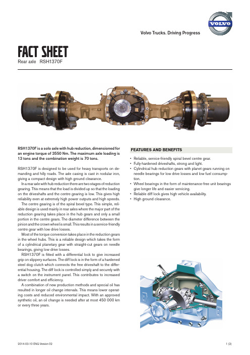
Volvo Trucks. Driving ProgressRSH1370F is a solo axle with hub reduction, dimensioned for an engine torque of 3550 Nm. The maximum axle loading is 13 tons and the combination weight is 70 tons.RSH1370F is designed to be used for heavy transports on de-manding and hilly roads. The axle casing is cast in nodular iron, giving a compact design with high ground clearance.In a rear axle with hub reduction there are two stages of reduction gearing. This means that the load is divided up so that the loading on the driveshafts and the centre gearing is low. This gives high reliability even at extremely high power outputs and high speeds.The centre gearing is of the spiral bevel type. This simple, reli-able design is used mainly in rear axles where the major part of the reduction gearing takes place in the hub gears and only a small portion in the centre gears. The diameter difference between the pinion and the crown wheel is small. This results in a service-friendly centre gear with low drive losses.Most of the torque conversion takes place in the reduction gears in the wheel hubs. This is a reliable design which takes the form of a cylindrical planetary gear with straight-cut gears on needle bearings, giving low drive losses.RSH1370F is fitted with a differential lock to give increased grip on slippery surfaces. The diff lock is in the form of a hardened steel dog clutch which connects the free driveshaft to the differ-ential housing. The diff lock is controlled simply and securely with a switch on the instrument panel. This contributes to increased driver comfort and efficiency.A combination of new production methods and special oil has resulted in longer oil change intervals. This means lower operat-ing costs and reduced environmental impact. With an approved synthetic oil, an oil change is needed after at most 450 000 km or every three years.FACT SHEETRear axle RSH1370FFEATURES AND BENEFITS• Reliable, service-friendly spiral bevel centre gear.• Fully-hardened driveshafts, strong and light.• Cylindrical hub reduction gears with planet gears running on needle bearings for low drive losses and low fuel consump-tion.• Wheel bearings in the form of maintenance-free unit bearings give longer life and easier servicing.• Reliable diff lock gives high vehicle availability.• High ground clearance.FACT SHEET Rear axle RSH1370FAll components dimensioned for long service lifeThe rear axle housing is cast in nodular iron. The brackets and spring plates are integrated directly in the housing, resulting in a more compact construction.The torque is transferred in the final drive via the pinion to the crown wheel which is fitted in the differential housing with a sturdy screw joint.Both the crown wheel and pinion are made of special steel which is case-hardened to provide an extra-hard and durable surface, at the same time as the core itself is tough yet elastic so as to be able to absorb shock loads.The pinion is journalled directly in the final drive housing with two sturdy conical roller bearings which are placed at either end of the pinion shaft. The differential housing with the crown wheel is journalled with two conical roller bearings, one on either side of the differential.Hub reduction with high reliability and low drive lossesRSH1370F is fitted with reduction gears in each hub. The hub reduction gearing consists of a cylindrical planetary gear with straight-cut gears on needle bearings, giving low drive losses. The sun wheel is mounted on the driveshaft. From the sun wheel, the power is transferred to four planetary gears connected to the wheel hub. When the planetary gears are forced to rotate against the ring gear, which is rigidly fixed to the rear axle casing, the rota-tion speed is geared down.The wheel bearings are in the form of maintenance-free unit bear-ings. The entire hub with bearings can be removed and installed simply and safely without affecting the bearing clearance.Reliable differential lock gives high availability.The diff lock gives excellent grip on slippery surfaces. It is sturdily dimensioned to withstand the highest stresses.The diff lock is in the form of a hardened steel dog clutch which connects on of the driveshafts to the differential housing.The diff lock can be easily engaged from the driver’s position. This is done with a switch on the instrument panel which controls a solenoid valve, supplying compressed air to an operating cyl-inder in the rear axle. A lamp lights up on the instrument panel to indicate that the diff lock is engaged. The lamp only lights up when the diff lock is engaged, because the sensor which controls the lamp is operated directly and mechanically by the motion of the engagement arm.Differential lock engaged.Differential lock disengaged. Type designation ...............................................................................RSH1370F Gear ...........................................Single gear, spiral bevel with hub reduction Hub reduction ...........................................................Cylindrical planetary gear Weight including driveshafts, hubs and drum brakes ......................745 kg Weight including driveshafts, hubs and disc brakes ........................735 kg Crown wheel, diameter .........................................................................295 mm Driveshafts, diameter ................................................................................45 mm Maximum engine torque .....................................................................3550 Nm Max axle loading ..................................................................................13000 kg Max combination weight ....................................................................70000 kg Ratio with hub reduction FE FH/FM .....................................................................3.46:1 ................................3.46:1 .....................................................................3.61:1 ................................3.61:1 .....................................................................3.76:1 ................................3.76:1 .....................................................................4.12:1 ................................4.12:1 .....................................................................4.55:1 ................................4.55:1 .....................................................................4.67:1 ...................................................................................................................5.41:1 .....................................................................5.46:1.....................................................................6.18:1 .....................................................................7.21:1Oil change quantity:Air suspension .................................................................................................23 l Leaf suspension ..............................................................................................24 lSPECIFICATION。
旺威汽车维修指南说明书
Understanding Volkswagen Driver Assistance SystemsAn on-board computer requires 0.25 seconds or less to reactto an impending danger. A person only overcomes theirsurprise and reacts after about a one-second delay.DramatizationDramatizationTechConnect Feature ArticleToday’s Volkswagen vehicles are available with many systems to enhance drivers’ experiences on the road. Some systems, like windshield wipers, are considered basic. Other systems, like ABS and traction control, are more advanced. But the next level of driver assistance features is here. An on-board computer requires 0.25 seconds or less to react to an impending danger. A person only overcomes their surprise and reacts after about a one-second delay.These advanced driver assistance systems can not only help alert the driver to an impending collision, but can also intervene to help avoid them altogether. Vehicles can brake to avoid a collision, and caneven park itself. It may seem like these features would be reserved for the most high-line cars in the fleet. But even the Golf and Golf SportWagen are available with many of the latest Volkswagen Driver Assistance systems.Before any type of testing or diagnosis of a system can occur, we must understand how each system works. This is vital when working on new available Driver Assistance systems. If we don’t understand how a system should work, we will not be able to properly identify an issue with a system. Where To StartWhen it comes to available Driver Assistance systems, the components vary from system to system. Let’s start by identifying each available feature.Automatic Post-Collision BrakingThe Automatic Post-Collision Braking system that results in an airbag deployment can automatically brake, slowing the vehicle down after an initial collision. This system is designed to lessen the severity of a secondary impact. Automatic Post-Collision Braking can slow the vehicle to a speed of 6 mph, and can be overridden by accelerating or hard braking. Available on:• 2015: Golf, GTI, Golf R, e-Golf, Golf SportWagen, Touareg• 2016: Golf, GTI, Golf R, e-Golf, Golf SportWagen, Jetta TSI, Jetta GLI/Hybrid, Beetle, BeetleConvertible, Touareg, PassatAdaptive Cruise Control (ACC)Adaptive Cruise Control functions very much like traditional vehicle cruise control. The speed is set by the driver, and the vehicle is designed to maintain that set speed. A vehicle equipped with ACC can also regulate speed based on the speed of other vehicles ahead. If a vehicle is detected ahead, the car will attempt to keep a consistent set distance from the other vehicle. Adaptive Cruise Control can accelerate on its own to the maximum set speed, and can brake automatically if the vehicle in front slows down. Available on:• 2015: Touareg• 2016: Golf, (manual transmission) GTI (manualtransmission), Golf R (manual transmission), Golf SportWagen (manual transmission) , Jetta TSI/TDI (automatic/DSG) Passat (automatic/DSG) Adaptive Cruise Control (ACC) with Follow to StopMuch like Adaptive Cruise Control, ACC with Follow to Stop can regulate the vehicle speed. In additionto speed and distance regulation, ACC with Followto Stop can bring the vehicle to a complete stop in normal traffic flow. Pressing the accelerator pedal, orusing the Resume function on the ACC control leverMid-Range Radar Sensor, 2015 Jetta The ACC system identifies the vehicles in front. V8 N1 Spring 201626Driver Assistance Systemson CC will resume ACC based on the distance from the vehicle in front.Available on:• 2015: Touareg• 2016: Golf, (automatic/DSG), GTI (DSG), Golf SportWagen (automatic/DSG), Touareg Sensors used:• Front Long-Range and Mid-Range RadarsForward Collision WarningVehicles with Forward Collision Warning can help to monitor the distance to traffic ahead. The system helps warn the driver of critical front-end collision situations. An audible alert and a visual warning are displayed in the MFI display.Available on:• 2015 Golf, GTI, Golf SportWagen, sensor is located below the front grill• 2015 Jetta, sensor is located behind the Volkswagen logo on grill• Also available on Passat, Touareg, and CC as a function of Front Assist Sensors used:• Front Radar Sensors• Long-Range and Mid-RangeAutonomous Emergency Braking (Front Assist)Autonomous Emergency Braking is a system that takes Forward Collision Warning a step further. It can apply the brakes automatically if the sensors detect a potential collision. This is done in two stages. Stage one is a short, jolting braking maneuver. If the driver fails to react to the first alert, Autonomous Emergency Braking can initiate an automatic braking maneuver. This can slow the vehicle down, increasing braking force. However, at speeds below 19 mph there is no warning jolt.Sensor locations:• Golf family: below front grill and also has a camera in front of the inside rear view mirror • Jetta/CC/Passat: behind Volkswagen logo on grill • Touareg: Adjacent to front fog lights, and camera in front of the interior rear-view mirror. Available On:• 2015: Touareg• 2016: Golf, GTI, Golf R, e-Golf, Golf SportWagen, Jetta TSI, CC VR6, Touareg, PassatBlind Spot MonitorUsing two radars at the rear of the vehicle, Blind Spot Monitor can alert drivers to vehicles in adjacent lanes. The two sensors constantly scan for traffic in the vehicle’s blind spot. The system can scan a range of approximately 65 feet.LEDs in the side mirrors, or on the mirror housing in the Touareg, alert the driver to any vehicle in the blind spot. If the driver uses the turn signals, the LEDs flash to warn of a dangerous situation. Available On:• 2015: Jetta, Beetle, Beetle Convertible• 2016: Golf, GTI, Golf R, Golf SportWagen, Jetta, Beetle, Beetle Convertible, Passat Sensors used:• Rear RadarsSide Assist (Lane Change Assist)Available only on the 2015 and 2016 Touareg, Side Assist can aid the driver by monitoring traffic behind and next to the vehicle. The rear radarmonitors up to a distance of about 230 feet. A series of four indicator lights warn the driver of traffic. As a vehicle gets closer to the Touareg, more lights will illuminate. When an approaching vehicle is very close, all four indicators will be lit.Rear Traffic AlertWhether it’s a moving object like a passing car, or a stationary object like a trash can, Rear Traffic Alert can warn of objects crossing directly behind the vehicle. Not only that, but radar-based sensors are used to help warn of vehicles approaching from the side when backing up. Rear Traffic Alert can even apply the brakes when the vehicle is in reverse when the radar sensors detect a potential collision with a vehicle approaching from the side, and there is also a warning sound and, if equipped with ParkPilot, a visual warning as well.Available On:• 2015: Jetta, Beetle, Beetle Convertible• 2016: Golf, GTI, Golf R, Golf SportWagen, Jetta, Beetle, Beetle Convertible, Passat Sensors used:• Rear Radar SensorsLane Departure Warning (Lane Assist)While the system will not relieve the driver from any responsibility, Lane Assist can steer to keep the vehicle within the lanes and provide a visual alert to the driver if the vehicle attempts to change lanes27Volkswagen TechConnectV8 N1 Spring 2016without the use of a turn signal. The front camera on the windshield identifies lane markings on the road. It processes the signal to determine if the vehicle is staying in the lane or not. Lane Assist can be overridden by the driver at any time. Using the turn signal indicator will also switch Lane Assist to passive mode.Lane Departure Warning (Lane Assist) — TouaregThe Lane Departure Warning system on the Touareg functions differently than on other Volkswagen models. The Touareg system will not provide active steering intervention. If lane departure is detected, the system can send a signal to vibrate the steering wheel to gain the driver’s attention. There is also a visual indication in the multifunction display.Lane Assist — Golf, GTI, Golf R, Golf SportWagen, CC VR6, PassatOn these models Lane Departure Warning can provide active countersteer measures to help keep the vehicle in the lane. If the vehicle crosses the lane without using a turn signal, visual warning are given asking the driver to take over steering.Sensors used:• Multifunction CameraPark Distance Warning System (ParkPilot)Volkswagen’s ParkPilot uses ultrasonic sensors that can measure the distance from the car’s front and rear bumpers to objects near the car. An acoustic and/or visual signal can alert the driver if the vehicle gets too close to an object.Available On:• 2015: Golf, GTI, Golf R, e-Golf, Golf SportWagen, Jetta Hybrid, EOS, CC, Touareg• 2016: Golf, GTI, Golf R, e-Golf, Golf SportWagen, Jetta, EOS, CC VR6, Touareg, PassatSensors used:• Ultrasonic SensorsParking Steering Assistant (Park Assist)Available for the first time on some 2016 models, Park Assist can help steer the car into parallel and perpendicular parking spots in reverse. The Park Assist button is pressed once for parallel parking and twice for perpendicular parking. The driver only needs to operate the accelerator pedal and brake once the gear is selected. Park Assist canautomatically steer the vehicle into the parking spot. While traveling below 25 mph, Park Assist system can scan both left-hand and right-hand sides of the road for parking spots. The driver will stipulate which side of the road he wishes to park on by activating the turn signal. Once a parking spot is identified, the driver will need to shift into reverse and operate the accelerator and brake pedal. The Multi Function Indicator (MFI) display will advise the driver when to switch from reverse to forward, and back into reverse gear.The system can be deactivated at any time by:• Turning the steering wheel • Increasing speed above 4 mph • Pulling out of a parking space• Pressing the Park Assist button onceAvailable on:• 2016: Golf, GTI, Golf SportWagen, Passat, e-Golf Sensors used:• Ultrasonic SensorArea ViewArea View is a Touareg-only feature. Area View is a 360-degree surrounding monitoring system. It uses four cameras to transmit images of the complete area around the vehicle, into the central display on the center console. The system can create an overall view of the surrounding area from the perspective of avirtual overhead camera. This can be especially helpful for customers aligning their Touareg with a trailer. Available on:• 2015, 2016 TouaregSensor OverviewKnowing the location and function of the various sensors and cameras used in Volkswagen’s Driver Assist systems is very important. Identifying issues with Driver Assist systems may be as simple as a visual inspection. If the vehicle, for example, has acracked windshield near the front camera, bumpersTouareg camera will monitor approximately 260 ft (80 m) ahead28Driver Assistance Systemsdamaged, or radars obscured, proper performance may be affected. This can cause erratic behavior in many Driver Assistance systems.Front SensorsFor 2016, many Volkswagen vehicles have a single mid- range radar sensor. The Touareg has a different system with two long-range radar sensors . These radar sensors are used for the Adaptive Cruise Control (ACC) and/or Front Assist functions.Mid-Range SensorsThe MRR Distance Regulation Control Module J428 is located at the front center of the vehicle, either behind the VW emblem, or below the VW emblem in the center of the bumper cover.This is a radar sensor that helps detect vehicles and obstructions in front of the vehicle. It is used differently for different systems. This is also the rear sensor for the RTA and other functions that are located in the bumper corners. It has the following features: • It has a frequency of 77 GHz• To help keep ice off at lower temperatures, the MRR has a heater• Range: Up to 525 ft. (160 m)• Speed: 0 - 100 mph (0 - 160 km/h) The MRR sensor is not standard equipment. However, it is used on many 2015 and newer vehicles, with the exception of the Touareg.Long-Range Radar (LRR) SensorsThe Touareg uses two long-range radar sensors located next to the fog lamps. They are 3rdGeneration radar sensors with the following features: • Each sensor has four radar antenna units • They have a frequency of 77 GHz• To help keep ice off at lower temperatures, the LRR has a heated lens• Range: Up to 656 ft. (200 m)• Speed: 0 - 130 mph (0 - 210 km/h)This generation of dual radar sensors allows the entire width of a three-lane road to be scanned, from as far as 99 feet (30 m) away.Touareg Driver Assistance Front Camera.29Volkswagen TechConnectV8 N1 Spring 2016The Distance Regulation Control Module J428 is the master, and it is located inboard of the right fog lamp. Distance Regulation Control Module 2 J850 is the slave and is located inboard of the left fog lamp.Multifunctional Front CameraThis camera can detect vehicles that may also be visible to the front radar system by using an actual camera to monitor the area in front of the vehicle. It confirms that a vehicle is there through sensor fusion to improve performance in critical situations.The camera monitors the area in front of the vehicle when stationary, preparing for a restart of the ACC system. It can also support front assist features, as well as detect lane markings for lane departure warning (Lane Assist).Front Camera (except Touareg)The front camera is located on the inside of the windshield, in front of the rear view mirror. Driver Assistance Systems Front Camera R242 provides image information to the following driver assist systems including Lane Departure Warning (Lane Assist) and ACC with Front Assist.The front camera can detect a variety of objects, such as vehicles and lane markers. The position of any detected object is captured by the camera, then transferred to the Distance Regulation Control Module J428. J428 compares the camera object data with the data of objects detected and mapped using radar.Front camera R242 also has a built in heating element. The Window Defogger for Front Sensor System Z113 prevents the part of the windscreen directly in front of the camera from misting up or icing over.Camera Control Module J852 and camera R242 are incorporated into the same module. J852 sends information via the extended CAN bus to be used by the lane departure warning system.Front Camera — TouaregThe front camera for the Touareg is similar to other front camera systems. It is integrated into the mirror base and has the following features:• It is a color camera with 1024 x 512 resolution • The range can be up to 2624 ft. (800 m)• The horizontal opening angle is 42 degrees and the vertical angle is 21 degrees If the Touareg has ACC, there are additional components and image processing. The Image Processing Control Module J851 is used to process the images received by J852 Camera Control Module. Signals are sent along the fast FlexRay Data Bus, supplying information to control modules J428 Distance Regulation Control Module and J850 Distance Regulation Control Module 2.To calculate the dive angle of the vehicle about the Y-axis with greater speed and safety, the camera control module has a Pitch Rate Sensor G752, whichis connected via the Extended CAN.The illustration above shows the sensor monitoring area on a straight road. On winding roads, the Blind Spot Monitor operates up to a minimum curve radius of about 558 feet. If the curve radius is below the 558 feet limit, the system switches to a deactivated state since the radar beams being transmitted can no longer scan the full rear monitoring area.30Driver Assistance SystemsRear Radar SensorsSome vehicles have Blind Spot Monitor and Rear Traffic Alert. These systems have two radar sensors behind the rear bumper that scan traffic behind the vehicle. The area monitored (on each side of the vehicle) includes the side and rear. The side area extends from the rear corner of the vehicle to about the level of the B-pillar.For vehicles equipped with Rear Traffic Alert, radar sensors can measure the distance and the speed difference between the vehicle and an approaching object and use this to calculate the time until a possible collision (“Time to Collision”).Technical Radar Data and System Limitations• Detection angle of the radar sensors is approximately 110 degrees• Detection area is approximately 65 ft. (20 m) range • Speed range for own vehicle from 1-7.5 mph (1-12 km/h)• Speed range for the detected vehicle > 2.5 mph (4 km/h)• Reverse gear must be engagedWarning Sounds• An acoustic warning from the dash panel insert, if Park Distance Control is not installed • Beeping noise, if Park Distance Control is installed• Automatic braking does not occur if the brake pedal is being pressed6-Channel Ultrasound SensorsFor vehicles with Park Assist, two 6-channel ultrasound systems are used to monitor close range objects. This allows for assisted parallel and perpendicular parking.Special Tools and Related RepairsThe number of vehicle equipped with Driver Assistance features is on the rise. With this rise, a shift in repair processes comes right along with it. A repair that was once a quick and easy job now may require radar or camera calibration. If an earlier Volkswagen was put into service position (alternate language here perhaps?), proper bumper cover alignment was for cosmetics. Now forward radar sensors must be realigned in addition to the bumper alignment.Calibration of the forward radar sensor is required if any of the following occur:• Rear axle toe setting has been adjusted (thrust angle)• The Distance Regulation Control Module J428 has been removed and reinstalled• The front bumper support has been removed and installed• The front bumper support has become loose or has been moved• The misalignment angle is greater than –0.8° to +0.8° (see below)• The vehicle has been brought into the service position• When performing an alignment There are also some special tools required to service Driver Assist systems.• VAS 6262 - Hunter Alignment Machine• VAS 6430/3 - Basic set for calibration of VW vehicles with the ACC laser unit • VAS 6190/2 - ACC Adjuster • T10113 or T20 Driver• VAS 6430/4 - Calibration Board For Lane Guard System• HUN2018351 - Radar alignment kid • VAS Scan Tool W/ODIS Service• VAS 6350/4 - Calibration Tool - Lane Change Calibration Tool• VAS 6350/2 - Calibration Tool - Spacing Laser • VAS 6350 - Reversing Camera Calibration Tool • VAS 6350/6 - Peripheral Camera Calibration Device•This semi-automatic parking system allows for perpendicular parking (spaces 90 degrees to the lane) and parallel parking on the right or left of the lane. It will not only help the driver park the vehicle, but can also beused to get the vehicle out of parking spots.。
潍柴汽车维修手册说明书
6. 维修过程中避免制动块和制动盘沾染油污,若沾染油污则使用纱布打磨干净。 7. 切勿重复使用排出的制动液,排出的制动液应储存在专用的回收容器内。 8. 排气过程中要观察制动液壶的制动液液位,低于最低刻度线时,应及时补充。 9. 加注制动液且排气结束后,检查制动系统是否有泄漏;若有应及时给予排除,确保行
前蒸发器 ...........................................71B-39
更换..................................................... 71B-39
空调风道 ...........................................71B-40
更换..................................................... 71B-35
暖风机芯体........................................71B-38
更换..................................................... 71B-38
鼓风机 ...............................................71B-30
更换..................................................... 71B-30
调速模块 ...........................................71B-31
更换..................................................... 71B-31
VOLVO发动机说明书16L
VOLVO发动机说明书16L VOLVO发动机说明书16L1、简介1.1 产品概述1.2 技术规格1.3 适用范围2、发动机结构2.1 发动机组成2.2 主要部件介绍2.2.1 缸体2.2.2 活塞组件2.2.3 链传动系统2.2.4 曲轴2.2.5 进气与排气系统2.2.6 燃油系统2.2.7 冷却系统2.2.8润滑系统2.2.9电气系统2.3 工作原理3、使用注意事项3.1 发动机启动与停止3.2 发动机运行参数监控3.3 发动机保养维护3.3.1 换油与滤清器更换 3.3.2 火花塞更换3.3.3 燃油喷嘴清洗3.3.4 故障灯处理方法3.3.5 发动机故障诊断4、故障排除与维修4.1 常见故障与排查方法4.2 维修流程4.2.1 维修工具准备4.2.2 维修操作步骤4.2.3 维修记录与报告填写5、安全操作指南5.1 安全警示5.2 出现故障时的应急措施5.3 灭火器的使用5.4 废弃物处理6、原厂授权与保修政策6.1 原厂授权维修点6.2 保修政策说明6.3 维修费用与收费标准7、附件7.1 配件列表7.2 维修手册及图纸7.3 保养记录表法律名词及注释:1、著作权法:指对知识产品及表现形式给予法律保护的法律规定。
2、商标法:指对商品、服务商标与商业名称等的使用和管理所做的法律规定。
3、合同法:指调整各种合同的签订、履行和效力等问题的法律规定。
4、侵权责任法:指对侵害他人合法权益所做的法律规定。
5、消费者权益保护法:指保护消费者合法权益的法律规范。
本文档涉及附件:1、发动机配件列表2、维修手册及图纸3、保养记录表。
沃尔沃d12系列发动机飞轮维修手册说明书
Volvo Trucks North America,Inc.Date Group No.Page TSI10.20032160042(11)ToolsSpecial ToolsThe following special tools are used to replace or repair components.The tools can beordered from Volvo;please use the specified part number when ordering.Volvo Trucks North America,Inc.Date Group No.Page TSI10.20032160043(11)Service Procedures2166-06-03-01Flywheel,Checking(Runout:Circumference and Surface)Y ou must read and understandthe precautions andguidelines in Service Information,Group21,"General Safety Practices,Engine"before performing this procedure.If you are not properly trained and certified in this procedure,ask your supervisor for training before you perform it.Special tools:9996956,9999696,9989876 1T2008997 Checking the flywheel for warp Use dial indicator9989876with magnetic base9999696 for this procedure.Position the probe against the flywheel and set the dial indicator at zero(0).2Remove the flywheel inspection cover and install flywheel turning tool9996956.Rotate the flywheel and read off the highest reading on the dial indicator.99969563The reading must not exceed0.20mm(0.008in.)ona measuring radius of150mm(6in.).In the case of excessive warp,remove the flywheel and check for dirt or unevenness between the flywheel and the crankshaft flange.0.20mm(0.008in.)150mm(6in.)Volvo Trucks North America,Inc.Date Group No.Page TSI10.20032160044(11)2166-03-02-02Flywheel,Replacement(In vehicle—Transmission and clutch removed.)Not Included:•“Flywheel,Overhaul”(rebush bearing bore,flywheelremoved)•“Flywheel,Checking”page3•“Rear Crankshaft Seal,Replacement”(flywheelremoved)•“Flywheel Ring Gear,Replacement”page10Prerequisites:•T ransmission removed.•Clutch assembly removed.Special tools:9996950Removal1T2006665Fig.2:Engine Speed Sensor location on flywheelhousing,D12A/BD12A/B:Remove sensor from the flywheel housing.Volvo Trucks North America,Inc.Date Group No.Page TSI10.20032160045(11)2W2003426Fig.3:Speed sensor location on flywheel casing,D12CD12C:Remove the speed sensor from the flywheelhousing.3T2006667Fig.4:Removing the flywheelAttach two bolts(M12x100)to the flywheel.Remove theflywheel bolts and lift off flywheel with the help of the bolts.Inspection4Minor scores or cracks in the friction face can be removedby grinding.However,do not remove more than0.5mm(0.02in.).In cases of more severe damage,replacethe flywheel.The flywheel depth(the distance from theclutch plate face to the clutch retaining plate face)mustremain unchanged.Therefore,the clutch retainingplate face must be ground down the same amountas the clutch plate face.0.5mm(0.02in.)5Install new flywheel pilot bearing.Volvo Trucks North America,Inc.Date Group No.Page TSI10.20032160046(11)Installation6Install new crankshaft rear seal.See“Rear Crankshaft,”216–003.7T2006668Contact surfaceCarefully clean the flywheel contact surface on thecrankshaft and the flywheel bolt holes in the crankshaft.8Carefully clean the contact surface on the flywheel.9Make sure that the flywheel alignment stud is in positionand undamaged.10T2007091Installing the flywheelLift the new flywheel into position with the help of twobolts(M12x100).Install the retaining bolts.Volvo Trucks North America,Inc.Date Group No.Page TSI10.20032160047(11)11T2006666Fig.5:Blocking tool installed,D12A/BT2008983Fig.6:Blocking tool installed,D12CRemove the inspection cover from beneath the flywheelhousing and install blocking tool9996950.999695012T orque-tighten the flywheel bolts,using the following2–step procedure:D12,D12A,D12B85±5Nm(63±4ft-lb)T urn the bolts another30±3±5Volvo Trucks North America,Inc.Date Group No.Page TSI10.20032160048(11)14T2006665Fig.7:Speed sensor location on flywheel housing,D12A/BW2003426Fig.8:Speed sensor location on flywheel casing,D12CClean and install the speed sensor.Check and adjustsensor distance as needed.See Service Specifications,Group20.Volvo Trucks North America,Inc.Date Group No.Page TSI10.20032160049(11)2169-03-03-01Flywheel Bearing,ReplacementClutch RemovedNot included:•Flywheel,Overhaul(rebush bearing bore,flywheelremoved)•“Flywheel,Checking”page3•Rear Crankshaft Seal,Replacement(flywheelremoved)Special tools:9991821,9992564,99918011T2006733Fig.9:Removing the flywheel bearingRemove the old flywheel bearing with tool9991821.99918212Clean the flywheel and check it for damage.3C2000452Fig.10:Installing the new flywheel bearingInstall the new flywheel bearing,using drift tool9992564and handle9991801.9992564,9991801Volvo Trucks North America,Inc.Date Group No.Page TSI10.200321600410(11)2166-03-05-01Flywheel Ring Gear,Replacement(Flywheel removed)Not Included:•Flywheel,Overhaul(rebush bearing bore,flywheelremoved)•Rear Crankshaft Seal,Replacement(flywheelremoved)•“Flywheel,Checking”page3C(360–400C(360–400Volvo Trucks North America,Inc.Date Group No.Page TSI10.200321600411(11)4T2006661Fig.13:Installing new ring gearInstall the heated ring gear onto the flywheel and tap itinto place using a soft drift and a hammer.5Allow the ring gear to air dry until cool.。
- 1、下载文档前请自行甄别文档内容的完整性,平台不提供额外的编辑、内容补充、找答案等附加服务。
- 2、"仅部分预览"的文档,不可在线预览部分如存在完整性等问题,可反馈申请退款(可完整预览的文档不适用该条件!)。
- 3、如文档侵犯您的权益,请联系客服反馈,我们会尽快为您处理(人工客服工作时间:9:00-18:30)。
volvo重型卡车维修手册
引言:本手册旨在为Volvo重型卡车的维修提供详细且全面的指南。
通过本手册,您将能够有效地进行卡车的维护和修理工作,确保其长
期的稳定运行和卓越性能。
第一章:卡车简介
1.1 Volvo重型卡车的特点和优势
本节将介绍Volvo重型卡车的优势,包括卓越的性能、可靠性和节
能环保的特点。
此外,还将介绍其创新的技术和安全功能。
1.2 卡车部件和系统概述
在本节中,将详细介绍卡车的各个重要部件和系统,包括发动机、
传动系统、转向系统等。
您将了解到各个部件的功能以及它们之间的
相互关系。
第二章:维护保养
2.1 基本维护知识
本节将介绍卡车的基本维护知识,包括定期保养、润滑油更换和滤
清器更换等。
您将了解到维护保养对保持卡车正常运行的重要性,并
掌握正确的维护方法。
2.2 维护时间表
在本节中,将提供Volvo重型卡车维护时间表的范例。
这将帮助您制定合理的维护计划,确保按时进行必要的检查和维护,降低故障的风险。
第三章:故障排除和修理
3.1 故障排除流程
本节将指导您如何进行故障排除和诊断,包括使用故障码读取设备和执行车辆自检程序。
通过本节的指导,您将能够准确识别故障原因并采取正确的修复措施。
3.2 常见故障及解决方法
在本节中,将列举Volvo重型卡车常见的故障,并提供相应的解决方法。
这将帮助您更好地应对各种常见问题,提高修理效率。
第四章:安全注意事项
4.1 工作环境和安全设施
本节将介绍维修工作的安全环境,包括工作场所的要求和各类安全设施的使用。
此外,还将提供应急情况处理的指导,确保维修过程中的安全。
4.2 个人保护措施
在本节中,将详细介绍维修工作中个人保护的必要措施,包括使用个人防护装备和遵守相关规定。
通过遵循这些措施,您将最大程度地降低维修过程中的伤害风险。
第五章:维修工具和设备
5.1 基本工具和设备
本节将介绍维修过程中常用的工具和设备,包括手工工具、电动工具、测量设备等。
您将了解到正确使用这些工具和设备的方法,以提
高维修效率和质量。
5.2 特殊工具和设备
在本节中,将介绍用于特定维修任务的特殊工具和设备。
这些工具
和设备在特定场景下,可以帮助您更好地完成复杂的维修工作。
结语:本维修手册旨在成为您维修Volvo重型卡车的权威指南。
通
过仔细阅读并严格按照手册指南操作,您将能够高效、有效地进行卡
车的维修和保养工作。
我们相信,对于一名专业的维修技师而言,这
本手册将成为您不可或缺的工具和指导。
感谢您选择Volvo重型卡车,我们将竭诚为您提供持续的技术支持和服务。