volvo重型卡车维修手册
重型汽车维修手册
重型汽车维修手册2007-02-15 12:53重型汽车将会分为公路运输车辆和工程、码头、油田、矿山等工程用车辆。
公路运输由于受国家法规的限制,将很快向多轴化、大马力方向发展。
如8x4、10x4等车型;而其他工程用车辆车型将会继续得到巩固和发展。
随着整个重型汽车市场的发展变化,其主要总成"车桥"也会随之发生变化。
在公路运输车辆向大吨位、多轴化、大马力方向发展同时,使得其驱动桥总成也向传动效率高的单级减速方向发展,也会相应带动非驱动桥,如转向前轴和承载轴的增长。
而作为双级减速的STR驱动桥将会继续巩固工程车辆的市场。
公路运输以10T及以上级单级减速驱动桥、承载轴为主;工程、港口等用车以10T级以上双级减速驱动桥为主.斯太尔平台中济南重汽、陕西重汽、重庆红岩及福田欧曼作为四强,将控制国内重卡平台30%以上的份额。
未来几年斯太尔平台的竞争将更趋激烈化。
动力转向系统转向机采用整体式液压动力转向系统。
装用引进德国ZF公司技术生产的叶片泵和转向机。
转向机仅有两种规格,以适应转向扭矩不同的全轮驱动与公路用车对转向的不同需要。
转向助力泵参数型号转速(转/分) 流量(升/分) 排量(毫升/转) 最大压力(巴) 流量检测叶片宽度(毫米) 重量(公斤) 生产厂家转速(转/分) 最大压力(巴) 最小流量(升/分)ZF7672 750-3900 6-16 13.5 130 500 50 5.5 16 4.7ZF7673 500-3500 9-20 16.5 130 500 50 6.6 19.54.3ZF7674 500-3500 12-25 20.5 130 500 50 8.0 23.54.4ZYB-1316 500-3900 16-20 16.5 130 500 50 6.6秦川机床厂动力转向系统的检查和调整转向机的拆装修理必须在规定的清洁条件下,以及必须要有一定修理技能的人员还要依据于一定的工具和设备才能完成。
沃尔沃汽车手册说明书

硬盘驱动器 进寻请请远..................... 旧拨
媒体播 器 - 兼容文件格式............ 旧择
通过 致U下/U分B 输入 接外部音源......... 旧只
通过 致U下/U分B 输入 接外部音源......... 旧叫
使用中 的按钮和 制或方向盘 侧的键 盘, 启动或解除*功能和 行许多ď 的
置
按č MY重台AR,显示Đ车 驾驶和 制有关的
所有 定,例如 Cit本 分且f优t本 和警 自
动风扇转
定时钟等
中 中的 制面
示仅用作示意 - 功能的
数量和按钮的 置 选定的 备和具体 场而
异 航 * - 寻AV , 参 阅 ĕ 门 的 附 录
分优n账u账 航系统 音响和媒体 - RADI导 MEDIA TEL*,
参阅 附录的相关章节
功 能 置 - MY重 台AR , 参 阅 销同 C致R 进 码古详远
}}
* 选配件/附件的更多信息, 查看 言
只
01重 言
口古
车 互联网 接 -
*,
参阅
古
附录
车 中的电子版 车 手
选 č角的信息符 ,获 电子 车Ľ手册
®
03B速u优tooth 免提电话 - 音量 置........ 拨拨
电话簿............................... 拨择 电话簿 - 快 搜索联系人.............. 拨择 电话簿 - 中 Č的 符表键盘........ 拨择 电话簿 - 搜索联系人.................. 拨只 语音识别............................. 拨只 语音识别的语言选 ................... 拨叫 语音识别的帮助功能................... 拨9 语音识别 - 置...................... 拨9 语音识别 - 语音指 .................. 择口 语音识别 - 快 指 .................. 择口 语音识别 - 移动电话.................. 择口 语音识别 - 收音机.................... 择古 语音识别 - 多媒体.................... 择古 联网车 ............................. 择该 车 调制解调器 *..................... 择旧
VOLVO发动机维修手册

维护保养计划表 ........................................ 18 维护保养计划表 .............................................. 18
简介..................................................................... 6 环保有责............................................................ 6 磨合 ................................................................... 6 燃油和润滑油..................................................... 6 维护保养和备件 ....................................................6 经认证的发动机 ................................................. 7
发动机使用说明书
发电机组和工业用发动机
4-7升(EDC 4)
前言
Volvo Penta 工业发动机的用户遍布世界各地,无论是移动的还是固定应 用,在可以想象得到的各种严酷工作环境中,您都可以找到它们。
经历了 90 余年的发动机制造历史,Volvo Penta 这个品牌已经成为运行 可靠、技术创新、性能一流和使用寿命长的代名词。我们坚信这些特点也 正是您对新 Volvo Penta 工业发动机的期盼和要求。
故障跟踪 ................................................. 37 征兆和可能原因....................................... 37
旺威汽车维修指南说明书
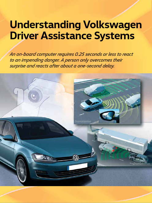
Understanding Volkswagen Driver Assistance SystemsAn on-board computer requires 0.25 seconds or less to reactto an impending danger. A person only overcomes theirsurprise and reacts after about a one-second delay.DramatizationDramatizationTechConnect Feature ArticleToday’s Volkswagen vehicles are available with many systems to enhance drivers’ experiences on the road. Some systems, like windshield wipers, are considered basic. Other systems, like ABS and traction control, are more advanced. But the next level of driver assistance features is here. An on-board computer requires 0.25 seconds or less to react to an impending danger. A person only overcomes their surprise and reacts after about a one-second delay.These advanced driver assistance systems can not only help alert the driver to an impending collision, but can also intervene to help avoid them altogether. Vehicles can brake to avoid a collision, and caneven park itself. It may seem like these features would be reserved for the most high-line cars in the fleet. But even the Golf and Golf SportWagen are available with many of the latest Volkswagen Driver Assistance systems.Before any type of testing or diagnosis of a system can occur, we must understand how each system works. This is vital when working on new available Driver Assistance systems. If we don’t understand how a system should work, we will not be able to properly identify an issue with a system. Where To StartWhen it comes to available Driver Assistance systems, the components vary from system to system. Let’s start by identifying each available feature.Automatic Post-Collision BrakingThe Automatic Post-Collision Braking system that results in an airbag deployment can automatically brake, slowing the vehicle down after an initial collision. This system is designed to lessen the severity of a secondary impact. Automatic Post-Collision Braking can slow the vehicle to a speed of 6 mph, and can be overridden by accelerating or hard braking. Available on:• 2015: Golf, GTI, Golf R, e-Golf, Golf SportWagen, Touareg• 2016: Golf, GTI, Golf R, e-Golf, Golf SportWagen, Jetta TSI, Jetta GLI/Hybrid, Beetle, BeetleConvertible, Touareg, PassatAdaptive Cruise Control (ACC)Adaptive Cruise Control functions very much like traditional vehicle cruise control. The speed is set by the driver, and the vehicle is designed to maintain that set speed. A vehicle equipped with ACC can also regulate speed based on the speed of other vehicles ahead. If a vehicle is detected ahead, the car will attempt to keep a consistent set distance from the other vehicle. Adaptive Cruise Control can accelerate on its own to the maximum set speed, and can brake automatically if the vehicle in front slows down. Available on:• 2015: Touareg• 2016: Golf, (manual transmission) GTI (manualtransmission), Golf R (manual transmission), Golf SportWagen (manual transmission) , Jetta TSI/TDI (automatic/DSG) Passat (automatic/DSG) Adaptive Cruise Control (ACC) with Follow to StopMuch like Adaptive Cruise Control, ACC with Follow to Stop can regulate the vehicle speed. In additionto speed and distance regulation, ACC with Followto Stop can bring the vehicle to a complete stop in normal traffic flow. Pressing the accelerator pedal, orusing the Resume function on the ACC control leverMid-Range Radar Sensor, 2015 Jetta The ACC system identifies the vehicles in front. V8 N1 Spring 201626Driver Assistance Systemson CC will resume ACC based on the distance from the vehicle in front.Available on:• 2015: Touareg• 2016: Golf, (automatic/DSG), GTI (DSG), Golf SportWagen (automatic/DSG), Touareg Sensors used:• Front Long-Range and Mid-Range RadarsForward Collision WarningVehicles with Forward Collision Warning can help to monitor the distance to traffic ahead. The system helps warn the driver of critical front-end collision situations. An audible alert and a visual warning are displayed in the MFI display.Available on:• 2015 Golf, GTI, Golf SportWagen, sensor is located below the front grill• 2015 Jetta, sensor is located behind the Volkswagen logo on grill• Also available on Passat, Touareg, and CC as a function of Front Assist Sensors used:• Front Radar Sensors• Long-Range and Mid-RangeAutonomous Emergency Braking (Front Assist)Autonomous Emergency Braking is a system that takes Forward Collision Warning a step further. It can apply the brakes automatically if the sensors detect a potential collision. This is done in two stages. Stage one is a short, jolting braking maneuver. If the driver fails to react to the first alert, Autonomous Emergency Braking can initiate an automatic braking maneuver. This can slow the vehicle down, increasing braking force. However, at speeds below 19 mph there is no warning jolt.Sensor locations:• Golf family: below front grill and also has a camera in front of the inside rear view mirror • Jetta/CC/Passat: behind Volkswagen logo on grill • Touareg: Adjacent to front fog lights, and camera in front of the interior rear-view mirror. Available On:• 2015: Touareg• 2016: Golf, GTI, Golf R, e-Golf, Golf SportWagen, Jetta TSI, CC VR6, Touareg, PassatBlind Spot MonitorUsing two radars at the rear of the vehicle, Blind Spot Monitor can alert drivers to vehicles in adjacent lanes. The two sensors constantly scan for traffic in the vehicle’s blind spot. The system can scan a range of approximately 65 feet.LEDs in the side mirrors, or on the mirror housing in the Touareg, alert the driver to any vehicle in the blind spot. If the driver uses the turn signals, the LEDs flash to warn of a dangerous situation. Available On:• 2015: Jetta, Beetle, Beetle Convertible• 2016: Golf, GTI, Golf R, Golf SportWagen, Jetta, Beetle, Beetle Convertible, Passat Sensors used:• Rear RadarsSide Assist (Lane Change Assist)Available only on the 2015 and 2016 Touareg, Side Assist can aid the driver by monitoring traffic behind and next to the vehicle. The rear radarmonitors up to a distance of about 230 feet. A series of four indicator lights warn the driver of traffic. As a vehicle gets closer to the Touareg, more lights will illuminate. When an approaching vehicle is very close, all four indicators will be lit.Rear Traffic AlertWhether it’s a moving object like a passing car, or a stationary object like a trash can, Rear Traffic Alert can warn of objects crossing directly behind the vehicle. Not only that, but radar-based sensors are used to help warn of vehicles approaching from the side when backing up. Rear Traffic Alert can even apply the brakes when the vehicle is in reverse when the radar sensors detect a potential collision with a vehicle approaching from the side, and there is also a warning sound and, if equipped with ParkPilot, a visual warning as well.Available On:• 2015: Jetta, Beetle, Beetle Convertible• 2016: Golf, GTI, Golf R, Golf SportWagen, Jetta, Beetle, Beetle Convertible, Passat Sensors used:• Rear Radar SensorsLane Departure Warning (Lane Assist)While the system will not relieve the driver from any responsibility, Lane Assist can steer to keep the vehicle within the lanes and provide a visual alert to the driver if the vehicle attempts to change lanes27Volkswagen TechConnectV8 N1 Spring 2016without the use of a turn signal. The front camera on the windshield identifies lane markings on the road. It processes the signal to determine if the vehicle is staying in the lane or not. Lane Assist can be overridden by the driver at any time. Using the turn signal indicator will also switch Lane Assist to passive mode.Lane Departure Warning (Lane Assist) — TouaregThe Lane Departure Warning system on the Touareg functions differently than on other Volkswagen models. The Touareg system will not provide active steering intervention. If lane departure is detected, the system can send a signal to vibrate the steering wheel to gain the driver’s attention. There is also a visual indication in the multifunction display.Lane Assist — Golf, GTI, Golf R, Golf SportWagen, CC VR6, PassatOn these models Lane Departure Warning can provide active countersteer measures to help keep the vehicle in the lane. If the vehicle crosses the lane without using a turn signal, visual warning are given asking the driver to take over steering.Sensors used:• Multifunction CameraPark Distance Warning System (ParkPilot)Volkswagen’s ParkPilot uses ultrasonic sensors that can measure the distance from the car’s front and rear bumpers to objects near the car. An acoustic and/or visual signal can alert the driver if the vehicle gets too close to an object.Available On:• 2015: Golf, GTI, Golf R, e-Golf, Golf SportWagen, Jetta Hybrid, EOS, CC, Touareg• 2016: Golf, GTI, Golf R, e-Golf, Golf SportWagen, Jetta, EOS, CC VR6, Touareg, PassatSensors used:• Ultrasonic SensorsParking Steering Assistant (Park Assist)Available for the first time on some 2016 models, Park Assist can help steer the car into parallel and perpendicular parking spots in reverse. The Park Assist button is pressed once for parallel parking and twice for perpendicular parking. The driver only needs to operate the accelerator pedal and brake once the gear is selected. Park Assist canautomatically steer the vehicle into the parking spot. While traveling below 25 mph, Park Assist system can scan both left-hand and right-hand sides of the road for parking spots. The driver will stipulate which side of the road he wishes to park on by activating the turn signal. Once a parking spot is identified, the driver will need to shift into reverse and operate the accelerator and brake pedal. The Multi Function Indicator (MFI) display will advise the driver when to switch from reverse to forward, and back into reverse gear.The system can be deactivated at any time by:• Turning the steering wheel • Increasing speed above 4 mph • Pulling out of a parking space• Pressing the Park Assist button onceAvailable on:• 2016: Golf, GTI, Golf SportWagen, Passat, e-Golf Sensors used:• Ultrasonic SensorArea ViewArea View is a Touareg-only feature. Area View is a 360-degree surrounding monitoring system. It uses four cameras to transmit images of the complete area around the vehicle, into the central display on the center console. The system can create an overall view of the surrounding area from the perspective of avirtual overhead camera. This can be especially helpful for customers aligning their Touareg with a trailer. Available on:• 2015, 2016 TouaregSensor OverviewKnowing the location and function of the various sensors and cameras used in Volkswagen’s Driver Assist systems is very important. Identifying issues with Driver Assist systems may be as simple as a visual inspection. If the vehicle, for example, has acracked windshield near the front camera, bumpersTouareg camera will monitor approximately 260 ft (80 m) ahead28Driver Assistance Systemsdamaged, or radars obscured, proper performance may be affected. This can cause erratic behavior in many Driver Assistance systems.Front SensorsFor 2016, many Volkswagen vehicles have a single mid- range radar sensor. The Touareg has a different system with two long-range radar sensors . These radar sensors are used for the Adaptive Cruise Control (ACC) and/or Front Assist functions.Mid-Range SensorsThe MRR Distance Regulation Control Module J428 is located at the front center of the vehicle, either behind the VW emblem, or below the VW emblem in the center of the bumper cover.This is a radar sensor that helps detect vehicles and obstructions in front of the vehicle. It is used differently for different systems. This is also the rear sensor for the RTA and other functions that are located in the bumper corners. It has the following features: • It has a frequency of 77 GHz• To help keep ice off at lower temperatures, the MRR has a heater• Range: Up to 525 ft. (160 m)• Speed: 0 - 100 mph (0 - 160 km/h) The MRR sensor is not standard equipment. However, it is used on many 2015 and newer vehicles, with the exception of the Touareg.Long-Range Radar (LRR) SensorsThe Touareg uses two long-range radar sensors located next to the fog lamps. They are 3rdGeneration radar sensors with the following features: • Each sensor has four radar antenna units • They have a frequency of 77 GHz• To help keep ice off at lower temperatures, the LRR has a heated lens• Range: Up to 656 ft. (200 m)• Speed: 0 - 130 mph (0 - 210 km/h)This generation of dual radar sensors allows the entire width of a three-lane road to be scanned, from as far as 99 feet (30 m) away.Touareg Driver Assistance Front Camera.29Volkswagen TechConnectV8 N1 Spring 2016The Distance Regulation Control Module J428 is the master, and it is located inboard of the right fog lamp. Distance Regulation Control Module 2 J850 is the slave and is located inboard of the left fog lamp.Multifunctional Front CameraThis camera can detect vehicles that may also be visible to the front radar system by using an actual camera to monitor the area in front of the vehicle. It confirms that a vehicle is there through sensor fusion to improve performance in critical situations.The camera monitors the area in front of the vehicle when stationary, preparing for a restart of the ACC system. It can also support front assist features, as well as detect lane markings for lane departure warning (Lane Assist).Front Camera (except Touareg)The front camera is located on the inside of the windshield, in front of the rear view mirror. Driver Assistance Systems Front Camera R242 provides image information to the following driver assist systems including Lane Departure Warning (Lane Assist) and ACC with Front Assist.The front camera can detect a variety of objects, such as vehicles and lane markers. The position of any detected object is captured by the camera, then transferred to the Distance Regulation Control Module J428. J428 compares the camera object data with the data of objects detected and mapped using radar.Front camera R242 also has a built in heating element. The Window Defogger for Front Sensor System Z113 prevents the part of the windscreen directly in front of the camera from misting up or icing over.Camera Control Module J852 and camera R242 are incorporated into the same module. J852 sends information via the extended CAN bus to be used by the lane departure warning system.Front Camera — TouaregThe front camera for the Touareg is similar to other front camera systems. It is integrated into the mirror base and has the following features:• It is a color camera with 1024 x 512 resolution • The range can be up to 2624 ft. (800 m)• The horizontal opening angle is 42 degrees and the vertical angle is 21 degrees If the Touareg has ACC, there are additional components and image processing. The Image Processing Control Module J851 is used to process the images received by J852 Camera Control Module. Signals are sent along the fast FlexRay Data Bus, supplying information to control modules J428 Distance Regulation Control Module and J850 Distance Regulation Control Module 2.To calculate the dive angle of the vehicle about the Y-axis with greater speed and safety, the camera control module has a Pitch Rate Sensor G752, whichis connected via the Extended CAN.The illustration above shows the sensor monitoring area on a straight road. On winding roads, the Blind Spot Monitor operates up to a minimum curve radius of about 558 feet. If the curve radius is below the 558 feet limit, the system switches to a deactivated state since the radar beams being transmitted can no longer scan the full rear monitoring area.30Driver Assistance SystemsRear Radar SensorsSome vehicles have Blind Spot Monitor and Rear Traffic Alert. These systems have two radar sensors behind the rear bumper that scan traffic behind the vehicle. The area monitored (on each side of the vehicle) includes the side and rear. The side area extends from the rear corner of the vehicle to about the level of the B-pillar.For vehicles equipped with Rear Traffic Alert, radar sensors can measure the distance and the speed difference between the vehicle and an approaching object and use this to calculate the time until a possible collision (“Time to Collision”).Technical Radar Data and System Limitations• Detection angle of the radar sensors is approximately 110 degrees• Detection area is approximately 65 ft. (20 m) range • Speed range for own vehicle from 1-7.5 mph (1-12 km/h)• Speed range for the detected vehicle > 2.5 mph (4 km/h)• Reverse gear must be engagedWarning Sounds• An acoustic warning from the dash panel insert, if Park Distance Control is not installed • Beeping noise, if Park Distance Control is installed• Automatic braking does not occur if the brake pedal is being pressed6-Channel Ultrasound SensorsFor vehicles with Park Assist, two 6-channel ultrasound systems are used to monitor close range objects. This allows for assisted parallel and perpendicular parking.Special Tools and Related RepairsThe number of vehicle equipped with Driver Assistance features is on the rise. With this rise, a shift in repair processes comes right along with it. A repair that was once a quick and easy job now may require radar or camera calibration. If an earlier Volkswagen was put into service position (alternate language here perhaps?), proper bumper cover alignment was for cosmetics. Now forward radar sensors must be realigned in addition to the bumper alignment.Calibration of the forward radar sensor is required if any of the following occur:• Rear axle toe setting has been adjusted (thrust angle)• The Distance Regulation Control Module J428 has been removed and reinstalled• The front bumper support has been removed and installed• The front bumper support has become loose or has been moved• The misalignment angle is greater than –0.8° to +0.8° (see below)• The vehicle has been brought into the service position• When performing an alignment There are also some special tools required to service Driver Assist systems.• VAS 6262 - Hunter Alignment Machine• VAS 6430/3 - Basic set for calibration of VW vehicles with the ACC laser unit • VAS 6190/2 - ACC Adjuster • T10113 or T20 Driver• VAS 6430/4 - Calibration Board For Lane Guard System• HUN2018351 - Radar alignment kid • VAS Scan Tool W/ODIS Service• VAS 6350/4 - Calibration Tool - Lane Change Calibration Tool• VAS 6350/2 - Calibration Tool - Spacing Laser • VAS 6350 - Reversing Camera Calibration Tool • VAS 6350/6 - Peripheral Camera Calibration Device•This semi-automatic parking system allows for perpendicular parking (spaces 90 degrees to the lane) and parallel parking on the right or left of the lane. It will not only help the driver park the vehicle, but can also beused to get the vehicle out of parking spots.。
潍柴汽车维修手册说明书

6. 维修过程中避免制动块和制动盘沾染油污,若沾染油污则使用纱布打磨干净。 7. 切勿重复使用排出的制动液,排出的制动液应储存在专用的回收容器内。 8. 排气过程中要观察制动液壶的制动液液位,低于最低刻度线时,应及时补充。 9. 加注制动液且排气结束后,检查制动系统是否有泄漏;若有应及时给予排除,确保行
前蒸发器 ...........................................71B-39
更换..................................................... 71B-39
空调风道 ...........................................71B-40
更换..................................................... 71B-35
暖风机芯体........................................71B-38
更换..................................................... 71B-38
鼓风机 ...............................................71B-30
更换..................................................... 71B-30
调速模块 ...........................................71B-31
更换..................................................... 71B-31
volvo重型卡车维修手册
volvo重型卡车维修手册引言:本手册旨在为Volvo重型卡车的维修提供详细且全面的指南。
通过本手册,您将能够有效地进行卡车的维护和修理工作,确保其长期的稳定运行和卓越性能。
第一章:卡车简介1.1 Volvo重型卡车的特点和优势本节将介绍Volvo重型卡车的优势,包括卓越的性能、可靠性和节能环保的特点。
此外,还将介绍其创新的技术和安全功能。
1.2 卡车部件和系统概述在本节中,将详细介绍卡车的各个重要部件和系统,包括发动机、传动系统、转向系统等。
您将了解到各个部件的功能以及它们之间的相互关系。
第二章:维护保养2.1 基本维护知识本节将介绍卡车的基本维护知识,包括定期保养、润滑油更换和滤清器更换等。
您将了解到维护保养对保持卡车正常运行的重要性,并掌握正确的维护方法。
2.2 维护时间表在本节中,将提供Volvo重型卡车维护时间表的范例。
这将帮助您制定合理的维护计划,确保按时进行必要的检查和维护,降低故障的风险。
第三章:故障排除和修理3.1 故障排除流程本节将指导您如何进行故障排除和诊断,包括使用故障码读取设备和执行车辆自检程序。
通过本节的指导,您将能够准确识别故障原因并采取正确的修复措施。
3.2 常见故障及解决方法在本节中,将列举Volvo重型卡车常见的故障,并提供相应的解决方法。
这将帮助您更好地应对各种常见问题,提高修理效率。
第四章:安全注意事项4.1 工作环境和安全设施本节将介绍维修工作的安全环境,包括工作场所的要求和各类安全设施的使用。
此外,还将提供应急情况处理的指导,确保维修过程中的安全。
4.2 个人保护措施在本节中,将详细介绍维修工作中个人保护的必要措施,包括使用个人防护装备和遵守相关规定。
通过遵循这些措施,您将最大程度地降低维修过程中的伤害风险。
第五章:维修工具和设备5.1 基本工具和设备本节将介绍维修过程中常用的工具和设备,包括手工工具、电动工具、测量设备等。
您将了解到正确使用这些工具和设备的方法,以提高维修效率和质量。
Volvo Trucks FL FE操作手册说明书
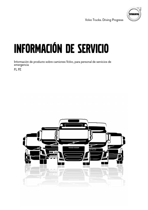
Volvo Trucks.Driving ProgressInformación de servicioInformación de producto sobre camiones Volvo,para personal de servicios de emergenciaFL FEPrólogoLas descripciones y los procedimientos de servicio se basan en diseños y en estudios demétodos realizados hasta septiembre2012.Los productos son desarrollados continuamente.Para los vehículos y componentes fabricados luego de la fecha mencionada,pueden por lo tanto corresponder especificaciones y métodos de reparación distintos.Cuando se considere que ello pesa significativamente para el manual presente,se publicaráuna versión actualizada del mismo que incluya los cambios.En la próxima edición del manual estas modificaciones quedan actualizadas.En las instrucciones en donde hay incluido el número de operación en el rubro,tan solo se trata de una referencia al tarifario VST(Volvo Standard Times).Las instrucciones sin número de operación en el rubro son solamente una información general y no hacen referencia a VST.En esta información de servicio se utilizan los siguientes niveles en observación y advertencia. Nota:Indica un método,práctica o condición que debe ser seguido para que la función del vehículo o componente sea realizada en la forma apropiada.Precaución:Indica un procedimiento que no es seguro y que puede acarrear daños al producto.Advertencia:Indica un procedimiento que no es seguro y que puede acarrear heridas al personal o graves daños al producto.Peligro:Indica un procedimiento que no es seguro y que puede causar heridas graves al personal e incluso la muerte.Volvo Truck CorporationGöteborg,SwedenNúmero de pedido:89073870©2012Volvo Truck Corporation,Göteborg,SwedenInformación de productos-FE,FL Información de producto sobre servicios de emergencia de Volvo TrucksContenido•“Introducción”,página2•“Cabina”,página3•“Sistema eléctrico”,página4•“Habitáculo del conductor”,página7•“Ajuste del volante”,página7•“Sistema SCR”,página9IntroducciónT1008650 La finalidad de este documento es proporcionar informaciónsobre productos de tipo técnico,que pueda usarse para es-tablecer rutinas y métodos para actuaciones de salvamentoen accidentes de tráfico donde se haya visto involucrado uncamión Volvo.El presente documento se destina a los Equipos de salva-mento locales,responsables de actuaciones de salvamentoen el lugar del accidente.El documento contiene la siguienteinformación:•Cabina del conductor•Sistema eléctrico•Puesto de conducción y ajustes del volante•SRS/sistema de airbag•Sistema SCRCabinaLas cabinas antiguas están fabricadas en chapa de acero de materiales blandos unidos por soldadura.Por su lado,los modelos de cabina más modernos están fabricados en acero de alta resistencia.A continuación presentamos un dibujo esquemático de la es-tructura de cabina,donde las zonas de chapa de alta resis-tencia se han marcado de color gris claro y gris oscuro.Refuerzo decabinaC8063199Sistema eléctrico Recomendaciones generales:Hay dos tipos de interruptores para cortar la corriente eléc-trica del vehículo.Son el interruptor principal y el disyun-tor de ADR.Interruptor principal•El interruptor de suministro principal sólo funciona cuan-do el motor estádesconectado.NO corta la alimentación del tacógrafo,el sistema de cierre centralizado,la alarma Despuésde usarDisyuntor de ADR•En vehículos que transportan mercancías peligrosas de-be haber siempre un disyuntor de ADR.Cuando se usa este disyuntor se corta todo el sumi-nistro eléctrico independientemente de si el motor¡Advertencia!para desconectar Nota!Solamente la desconexión desde la batería o con el disyuntor de ADR corta TODO el suministro eléctrico.•Cuando se ha desconectado la alimentación de batería, se guarda energía en la unidad de mando de SRS duran-te unos segundos,tiempo suficiente para activar el air-bag o el tensor de cinturón de seguridad.Para asegurar que el sistema estádesenergizado,esperar unos3se-gundos después de desconectar la alimentación de labatería.•Antes de desconectar la corriente:¡Considerar la po-sible necesidad de abrir puertas o mover el asiento del conductor!(Ver:“Habitáculo del conductor”,página 7Si el asiento del conductor es ajustable eléctricamente,no seráposible ajustarlo después de cortar la electricidad porque el asiento no tiene mandos mecánicos.•La apariencia y la función varían entre diferentes inte-rruptores principales.Algunos modelos de camión care-cen de interruptor principal.¿Cómo se desconecta la corriente?•Desconectar el interruptor principal.No se desconec-tan todos los circuitos del camión;algunas partes especí-ficas del vehículo permanecen energizadas.No todas lascabinas tienen interruptor principal.•Interrumpir el circuito de batería soltando/cortando elcable de los bornes de batería.Ésta es la forma más se-gura de interrumpir la tensión.Se interrumpe toda la ten-sión,incluso del tacógrafo.Tener en cuenta que el vehículo sigue estando energiza-do si sólo se quita la llave de contacto.Con respecto aSRS,permanece energía almacenada en la unidad de man-do de SRS durante unos segundos después de cortarse elsuministro.Esta energía es suficiente para activar el airbag yel tensor de cinturón de seguridad durante hasta tres segun-dos después de cortar el suministro.La cifra indica la posición normal de la batería.1Caja de baterías de montaje lateral.Se puede montar en el lado izquierdo o derecho.2Caja de baterías de montaje posterior.T3072656Diferentes formas de cortar el suministro eléctrico:D.Interruptor principal telemandado.No existe en todos los vehículos.Pulsando el botón izquierdo dos veces dentro de cinco segundos,se desconecta el interruptor principal.Algunos circuitos permanecenenergizados.T301-7347C.Disyuntor de ADR.Sólo existe en vehículos que trans-portan mercancías peligrosas.Desconecta TODA lacorriente.C8063014B.Interruptor principal/interruptor de batería.Se encuentra en todos los vehículos.Algunos circuitos siguen excitados.A.Batería.Cuando se interrumpe el circuito de batería,empezar con el borne nega-tivo.Si es necesario cortar,hacerlo lo más cerca posible de la batería para reducir el riesgo de conexiones junto a los cables principales.Nota!¡Atención!No todos los componentes de la figura arri-ba están en todos los vehículos.Sistema de cierre centralizadoEl sistema de cierre centralizado se inmoviliza interrumpien-do el circuito de batería.En vehículos para transporte de mercancías peligrosas,el cierre centralizado también se in-moviliza desde el interruptor principal.Las puertas bloqueadas se pueden abrir desde el interior usando la empuñadura de apertura.Habitáculo del conductorDiseño del asientoExisten varios modelos de asiento para los diferentes mode-los de camión.El ajuste de posición de asiento vuelto atrás y adelante es en algunos casos mecánicos,pero los modelos más avanza-dos tienen ajuste eléctrico.Los modelos con ajuste mecánico se ajustan con una empu-ñadura situada debajo de la parte frontal del cojín de asiento,y los que tienen ajuste eléctrico se ajustan con un botón si-tuado en el lado izquierdo del asiento.Nota:los asientos con ajuste eléctrico no tienen sistema de ajuste mecánico.Para más información,ver:“Sistema eléctrico”,página 4Ajuste de asiento en sentidolongitudinalT8010409T8010449Ajuste con horquilla.Ajuste eléctrico.Ajuste del volanteHay un botón de operación neumática o una palanca mecá-nica en la columna de dirección.Cuando es necesario cortar o aserrar en el volante,la mane-ra más fácil es hacerlo en las zonas marcadas en blanco de acuerdo a la figura de abajo.El resto de las secciones están reforzadas.Perfil de refuerzo del volante y ajuste delvolanteT0013497T6009538Ajuste del volante.Cortar el volante.Sistema SCRRecomendaciones generales:•Cuando se para el motor,la solución de urea es bombea-da de vuelta al depósito de urea y se vacía la solución de urea del sistema SCR.Este proceso tarda unos dos minu-tos.Si se usa el interruptor de ADR para cortar la corrien-te antes de terminarse este proceso,el sistema puedeseguir estando presurizado y contener de solución deSi se usacuando•La urea es muy corrosiva y puede dañar conectores.Si la urea entra en contacto con conectores desenchufados, hay que cambiarlos de inmediato.No sirve de nada lim-piar porque la solución de urea se dispersa rápidamente en el cable,causando oxidación del metal.El derrameevaporaciónLas zonasen vehículosSistema SCREl sistema de urea es la parte del sistema de postratamientode los gases de escape que tienen algunos motores nuevospara cumplir con los requisitos de emisiones de Euro 4.Se inyecta una solución de urea en los gases de escape an-tes de que atraviesen el catalizador,para reducir las emisio-nes de óxidos de nitrógeno en los gases de escape.Los componentes principales del sistema SCR son:de-pósito de urea,unidad de bomba,unidad dosificadora y silenciador con catalizador incorporado.Sinopsis del sistema SCR y sus componentesprincipales:T20229851.Depósito de urea2.Unidad de bomba3.Unidad dosificadora4.SilenciadorSolución de ureaLa solución de urea,formada por agua destilada y un 32,5%de urea,es un líquido incoloro que puede tener un suaveolor a amoniaco.La solución de urea puede ser agresiva contra determinadosmateriales y se debe manipular con cuidado.La solución no es inflamable.A temperaturas altas la solución de urea se descompone enamoniaco y dióxido de carbono,y a temperaturas inferioresa –11°C la solución se puede congelar.La solución de urea es corrosiva a los metales,especialmen-te el cobre y el aluminio.Manipulación de la solución de urea:En caso de contacto con la piel:enjuague bien con agua tibia y quítese las prendas contaminadas.En caso de contacto con los ojos:enjuague bien con agua durante varios minutos y acuda a unmédico en caso necesario.En caso de inhalación:respire aire fresco y acuda a un médico en caso necesario. En caso de ingestión:beba agua89073870Spanish1.05Edición01 Volvo Truck Corporation。
Volvo 货车配置和尺寸说明书

Important NotesChassis DimensionsCab Height: +39 mm for CAB-CRW.Front Axle to Back of Cab: +1294 mm for CAB-CRW, +316 mm for CAB-SSLP. D-measure includes a front clearance of 50 mm and for rigid trucks also a subframe of 120 mm.Height can vary ± 20 mm for leaf and ± 10 mm for air suspension.All dimensions are for unladen chassis and any tag axles down. Chassis height used: CHH-LOW.Weight and dimensions are based upon the following tyres:Chassis weight includes oil, water, AdBlue, 0 litres fuel and without driver. Kerb weight can vary ± 3%.Turning diameters are theoretically calculated.Legal weights can differ from country to country.For more detailed weight information, including optional equipment weights, ask your Volvo sales contact to enter your specification into the Volvo WeightChassis Dimensions [mm]WB Wheelbase35003800410044004700500053005600590062006500A Overall Chassis Length6975 7425 7955 8425 8915 9615 9915 10425 10835 11430 11730 D Center of rear axle to front of body 2948 3248 3548 3848 4148 4448 4748 5048 5348 5648 5948 N Rear Overhang (Min.) 2055 1885 2445 2635 2835 2895 2895 3415 3295 3505 3755 NRear Overhang (Max.)2155230525352705289532953295 3505 3615 3910 3910Y Center of Gravity for Payload (Min.) 269 292 316 338 360 381 400 421 451 465 482 Y Center of Gravity for Payload (Max.) 709 771 834 895 958 1022 1079 1141 1208 1266 1324 W Body Length (Min.) 4477 4954 5428 5905 6380 6853 7337 7815 8280 8763 9248 W Body Length (Max.) 5048 5528 6008 6488 6968 7448 7928 8408 8888 9368 9848Chassis Weights [kg]Front Axle 2890 2890 2890 2895 2895 2905 2910 2915 2905 2920 2925 Rear Axle 1165 1180 1200 1215 1240 1285 1285 1305 1305 1345 1350 Kerb Weight4055 4070 4090 4110 4135 4190 4195 4220 4210 4265 4275 Payload (including body, driver, fuel, etc.) 7945 7930 7910 7890 7865 7810 7805 7780 7790 7735 7725Turning Diameter [mm]Turning Circle Diameter Kerb to Kerb 12400 13300 14200 15000 1590016800 17700 18600 19500 20400 21300 Turning Circle Diameter Wall to Wall13700 1460015500 16400 17300 18200 19100 20000 20900 21800 22700Plated Weights [kg]DesignGross Vehicle Weight12000 Gross Combination Weight 15500 Front Axle 4500 Rear Axle 8500■ Standard Equipment □ Optional EquipmentFor more detailed information about cab and powertrain equipment, please refer to separate specification sheets.For all possible options and combinations of options please consult your Volvo sales contact who can create a specification to match your requirements using the Volvo Sales Support system (VSS).■ CHH-LOW Chassis height low - approx. 850 mm above ground level□ CHH-MED Chassis height medium - approx. 900 mm above ground level■ RAD-A2V Rear air suspension, 1 axle - 1 driven□ CAB-CRW Crew cab □ CAB-DAY Day cab □ CAB-SSLP Comfort cab■ EU6SCR Euro 6 emission level with Selective Catalytic Reduction (SCR), particle filter and Exhaust Gas Recirculation (EGR)■ D5K210 Four cylinder diesel engine, 5.1 litre Euro 6 SCR + EGR (Diesel Particulate Filter), 210 hp, 800 Nm□ D5K240 Four cylinder diesel engine, 5.1 litre Euro 6 SCR + EGR (Diesel Particulate Filter), 240 hp, 900 Nm□ ATO1056 I-Sync, Automated manual 6 speed gearbox, 1070 Nm □ ATO8006 I-Sync, Automated manual 6 speed gearbox, 850 Nm ■ STO8006 Manual overdrive 6 speed gearbox, 850 Nm□ ZTO1006 Overdrive 6 speed manual ZF gearbox, 1050 Nm■ EBR-EPG Engine brake with Exhaust pressure governor, EPG■ RSS0819A Rear single reduction solo axle - axle load 8 tonnes, GCW 18.75 tonnes□ RSS1125A Rear single reduction solo axle - axle load 11 tonnes, GCW 25 tonnes□ RSS1132A Rear single reduction solo axle - axle load 11 tonnes, GCW 32.5 tonnesPackages□ DRIVEFL Driver convenience package FL□ VISIFL Visibility package FL - Optimizing the drivers field of vision around the cab□ AIRFLOW Airflow package FL - Includes adjustable roof spoiler, side deflector and sun visor□ AUDIODAB Audio System DAB■ AUDIOPD Audio Preparation DAB kit, incl. DAB-amplifierChassis ■ FST-PAR Front parabolic leaf suspension (normal stiffness)■ FAL4.5 Front axle load 4.5 tonnes □ FAL5.0 Front axle load 5.0 tonnes□ RAL10.6 Rear axle load 10.6 tonnes □ RAL10.9 Rear axle load 10.9 tonnes ■ RAL8.5 Rear axle load 8.5 tonnes □ RAL9.2 Rear axle load 9.2 tonnes □ RAL9.5 Rear axle load 9.5 tonnes□ EBS-MED EBS (Electronic Brake System) medium package ■ EBS-STD EBS (Electronic Brake System) standard package■ RST-AIR Rear air suspension■ SUSPL-E1 Remote control on wander-lead for air suspension levelling with 1 sensor on rear axle□ SUSPL-E3 Integral three dash switches for air suspension levelling control with 1 sensor■ FST6060 Frame section thickness - web 6.0 mm / flange 6.0 mm □ FST7070 Frame section thickness - web 7.0 mm / flange 7.0 mm □ FST8080 Frame section thickness - web 8.0 mm / flange 8.0 mm■ 2BATT170 Batteries 2x170 Ah□ ADR2 ADR adaptation, 1 switch in dashboard, 1 outside on back of cab■ R80P Right 80 litre plastic diesel tank Min volume 80l Max volume 430l■ UL-FUEL Without left diesel tank■ ADTP-R AdBlue tank on right hand side■ WHC-FIX1One fixed wheel chock□ TOWMBRH High mounted towing member, in centre of frame□ C-RO40AG Towing coupling Rockinger 400 G-145■ TOWF-NO1 One front towing device □ TOWF-NO2 Two front towing devices□ TOWR-ONE One rear towing device in frame end cross member□ TREL15 15 pol electrical trailer connector (ADR certified)□ TBC-EC Trailer brake connection, European Community□ RUP-FIX2 Fixed rear underrun protection, EC approved■ RFEND-T Transport mounted one-piece rear fenders□ 2024GSR General safety regulations 2024Rims and tyres □ RT-AL Brushed aluminium rims with std holes (long stud fixing) on allaxles□ RT-ALDP Dura-Bright polished aluminium rims with std holes (long studfixing) on all axles■ RT-STEEL Steel rims on all axles ■ SPWT-F Spare wheel with tyre equal to front wheel □ SWCP-LF Spare wheel carrier on left side in front of rear axle □ SWCP-R Spare wheel carrier transport mounted behind rear axle, onright-hand side (FH, FM)/below frame (FL,□ SWCP-T Spare wheel transport mounted on top of frame ■ SWCP-TP Spare wheel carrier transport mounted with the spare wheel ontop of the frame rails■ JACK-6T Jack, 6 tonnes □ JACK-8T Jack, 8 tonnes□ GAUGE-TP Tyre pressure gaugePowertrain equipment ■ CS39A-O Single plate clutch, plate diameter 395 mm □ TC-HWO Oil cooler for hydraulic transmissions – water/oil■ 1COMP500 Single cylinder air compressor 360 cc / 500 l/min □ AIRIN-FR Front air intake, chassis mounted on right hand side, ahead offront wheel■ AIRIN-HI High air intake □ AIRIN-RL Low air intake, chassis mounted behind cab on left hand side ■ ACL1ST Air cleaner with one filter element □ ACL1ST-S Air cleaner with additional filter element ■ 24AL110B Alternator 110 Ampere □ 24AL130B Alternator 130 Ampere □ CCV-C Closed crankcase ventilation ■ CCV-OX Open crankcase ventilation with oil separator and amaintenance free gas centrifuge■ EST-AID Engine start pre-heating element □ PTER-100 Rear engine mounted clutch independent power-take-off withflange connection (DIN 100 / ISO 7646)□ PTER-DIN Rear engine mounted clutch independent PTO with splinedshaft groove (female) for a close coupled pump (DIN 5462 / ISO 7653)□ PTER1400 Rear engine mounted clutch independent power-take-off withflange connection (SAE 1410 / ISO 7647)□ PR-HF4S PTO transmission, Hydrocar, flange connection, side mounted □ PR-HF4SH PTO transmission, Hydrocar, flange connection, side mounted,high speed□ PR-HF6S PTO transmission, Hydrocar, flange connection, side mounted □ PR-HP4S PTO transmission, Hydrocar, pump connection, side mounted □ PR-HP4SH PTO transmission, Hydrocar, pump connection, side mounted,high speed□ PR-HP6S PTO transmission, Hydrocar, pump connection, side mounted □ PTR-FH5 Rear gearbox mounted Hydrocar S88 PTO with flangeconnection (DIN 90 / ISO 7646) for propeller shaft (450 Nm)(DIN 5462 / ISO 7653) for pump (450 Nm)□ HPG-F101 Gearbox mounted hydraulic pump F1-101, fixed displacement,single flow□ HPG-F41 Gearbox mounted hydraulic pump F1-41, fixed displacement,single flow□ HPG-F51 Gearbox mounted hydraulic pump F1-51, fixed displacement,single flow□ HPG-F61 Gearbox mounted hydraulic pump F1-61, fixed displacement,single flow□ HPG-F81 Gearbox mounted hydraulic pump F1-81, fixed displacement,single flow□ ETC Electronic throttle control - dash mounted switch for PTOspeed controlCab interior■ TAS-DIG4 Gen 4 one day digital tachograph, EC approved (GNSS &DSRC, EU 2020/1054)Cab exterior□ SUNV-B Exterior transparent dark grey front sun visor■ SUNV-PK Exterior front sun visor installation preparation kit (fasteners)□ AD-SIDES Short cab side air deflectors□ BEACON-P Prepared for roof beacons□ BEACONA2 2 amber beacon, roof mounted warning lampsSuperstructure preparations□ FBA-BTF Front body attachments for flexible body□ FBA-BTSF Front body attachments for semi-flexible body□ RBA-T2 Rear body attachments for helper frame□ TAILPREP Tail lift preparation kitServices□ TGW-4G Telematics gateway with 4G modem■ WVTA Whole Vehicle Type Approved■ Standard Equipment □ Optional EquipmentFor more detailed information about cab and powertrain equipment, please refer to separate specification sheets.For all possible options and combinations of options please consult your Volvo sales contact who can create a specification to match your requirements using the Volvo Sales Support system (VSS).。
- 1、下载文档前请自行甄别文档内容的完整性,平台不提供额外的编辑、内容补充、找答案等附加服务。
- 2、"仅部分预览"的文档,不可在线预览部分如存在完整性等问题,可反馈申请退款(可完整预览的文档不适用该条件!)。
- 3、如文档侵犯您的权益,请联系客服反馈,我们会尽快为您处理(人工客服工作时间:9:00-18:30)。
volvo重型卡车维修手册
一、概述
本手册旨在为VOLVO重型卡车维修人员提供一本详尽的维修指南,涵盖了VOLVO重型卡车的结构、工作原理、常见故障诊断与排除等方面的知识。
本手册旨在帮助维修人员更好地了解和掌握VOLVO重型卡车的维修技能,提高维修效率和质量。
二、车辆结构与工作原理
1. 车辆总体构造:VOLVO重型卡车由多个部分组成,包括发动机、底盘、电气系统等。
本章节将详细介绍各组成部分的名称、功能及相互关系。
同时,也会介绍车辆的总体布局,方便维修人员快速了解车辆的整体结构。
2. 发动机:详细介绍VOLVO重型卡车的发动机结构、工作原理及常见故障。
维修人员需要了解发动机的类型(柴油或汽油)、气缸数量和排量等关键信息。
3. 底盘:阐述底盘各组成部分的结构、工作原理及调整方法,包括悬挂、制动系统、传动系统等。
同时,也会介绍底盘的维护和保养方法,确保车辆的正常运行。
4. 电气系统:介绍电气系统的组成、工作原理及常见故障诊断与排除方法。
维修人员需要了解电气系统的基本组成,如蓄电池、发电机、保险丝等,并熟悉其工作原理。
三、维修工具与设备
本章节将介绍维修VOLVO重型卡车所需的常用工具和专用设备,包括工具的用途、使用方法及注意事项。
同时,也介绍了工具的摆放
和安全操作规范。
此外,还会列出一些必备的测试仪器和软件,以供维修人员参考。
四、故障诊断与排除
本手册将提供一系列常见故障的诊断与排除方法。
对于每个故障,维修人员将获得故障描述、可能的原因、诊断步骤以及相应的解决方法。
以下是一些常见的故障示例:
1. 启动困难:针对启动困难的问题,我们将提供原因分析和诊断方法,并提供相应的解决方法,如检查电池状态、清洁启动马达触点等。
2. 燃油消耗异常:对于燃油消耗异常的情况,我们将介绍可能的原因,如空气流量传感器故障、发动机磨损等,并提供相应的诊断与排除方法。
3. 制动系统故障:我们将介绍制动系统常见故障及诊断与排除方法,如制动踏板不回位、制动效能降低等。
4. 空调系统故障:针对空调系统故障,我们将提供诊断与排除方法,如检查制冷剂压力、更换空调滤清器等。
此外,本手册还将提供一些疑难故障的诊断与排除方法,以帮助维修人员解决实际问题。
同时,我们也会列举一些特殊情况下的应急处理方法,以备不时之需。
五、日常维护与保养
本章节将介绍VOLVO重型卡车的日常维护与保养知识,包括日常检查项目、润滑系统、冷却系统、轮胎更换与调整等。
通过正确的日常维护与保养,可以延长车辆的使用寿命,提高车辆的安全性。
此
外,还会介绍一些预防性维护的方法和周期,以减少车辆故障的发生。
六、附录
本手册的附录部分将提供一些有用的信息,包括常见故障代码含义及读取方法、维修案例分享等。
这些附录内容将有助于维修人员更好地理解和解决实际问题。
此外,我们还会列出一些重要的技术资料和网址,方便维修人员查阅和学习。
总之,《VOLVO重型卡车维修手册》是一本详尽的维修指南,旨在为VOLVO重型卡车维修人员提供帮助和支持。
本手册的内容全面且实用,希望能对维修人员的工作有所帮助。
在使用本手册时,请根据实际情况调整维修方法,以确保车辆安全可靠地运行。
现在让我们开始吧!
以上就是《VOLVO重型卡车维修手册》的大致内容,希望能够帮助到您。
以上内容仅供参考具体内容您可以根据自身需求进行调整和修改。