
眼镜蛇TT捣固机
眼镜蛇TT捣固机
一、眼镜蛇TT捣固机简介
眼镜蛇TT捣固机是内燃手持式振动捣固机,由一部二冲程发动机驱动,能够让发动机怠速运行可不触发冲击机构,适用于铁路线路、道岔的捣固作业。
更换镐钎后,也可以用于更换轨枕作业中的板结道床破碎工作。
与同类产品相比,具有操作简单、维护方便、冲击力大、效率高、减震好等特点,是铁路工务系统施工作的必备机具。
二、安全操作使用
1、人身安全
①、为了保证人身安全,作业人员要穿戴好劳动防护用品。
硬质帽子、眼镜、劳保鞋。
②、为了方便操作,在操作本机器时要用你的大腿做支撑。
③、眼镜蛇TT捣固机装有H.A.P.s。
(手护臂防系统),片簧震动。
④、避免在靠近易燃物品或者通风不良地区操作发动机。
2、设备安全
①、参看使用说明书了解维修保养的资料
②、正确配比两冲程燃油混合液,使用高质量风冷发动机二冲程机油,与汽油混合后加入汽油箱。
机油与汽油的比例大于1:30。
③、混合液中机油太少会造成润滑不足导致磨损增加。
机油太多则造成排气孔和烟道堵塞。
特别脏的过滤器应该更换。
④、机器超过两周不用时要放空燃油箱内燃油。
⑤、下插捣固时,不要过力横向扭动机器,以免造成减震簧片损坏。
⑥、启动机器前确保钎具完全插入钎套,且钎卡在正确的锁紧位置。
⑦、插装或更换镐钎时,(特别注意:施工中镐钎脱落要重新插装时)必须停机熄火进行!如着机时插装镐件,高速运转的气压活寨,会被突然受力撞击的夯锤活塞顶折气压连杆、并打碎机器箱体,造成设备事故。
3、正确操作与使用
①、开箱后将左右手柄安装好。
安装左手柄时,应将油门拉线蛇皮管护套用手推入机器、端口内,否则油门无怠速。
②、冷机启动。
将左手柄上的启动开关向里拨,向上关闭风门,压油泵,将手油泵汽油压满。
按入缸体右侧的减压阀按钮。
完全按下油门手柄,反复拉起动手柄,并压手油泵反复泵油。
当听到发动机有爆发声响后,向下打开风门一半,再次按下减压阀按钮,用力拉动启动手柄。
机器启动后,向下旋转风门手柄打开风门。
机播预热2-3分钟,即可开始工作。
③、热机重启动。
按入减压阀按钮,风门在打开位置,拉动起柄。
④、操作。
下压手柄触发机器冲击后,手把方向,主要靠机器自重下插捣固到轨枕下面。
⑤、作业时不要过分用力压手柄。
适当用力即可,如果钎具过分受压,将减震弹簧压死,可能会发生驱动系统和发动机的过热。
⑥、停机。
将左手柄上停机开关向外推,机器熄火。
三、日常检查
1、每日检查内容
①、坚持日常检查确保机器良好使用。
②、每天检查冲击机构油位。
把机器垂直放置,添加SAE15W/40柴油机油。
2、每周检查内容
①、每周检查齿轮箱注油口,打开机器后部灰色塑料外壳拧开左侧齿轮箱黑色油堵,加注SAE15W/40柴油机油。
机器直立时,加油孔即是油位。
②、每周清洁空气过滤器和箱体。
空滤器脏污会造成发动机过分磨损,也会引起排气孔堵寨和烟道碳化现象。
机器未装空滤器绝对不要使用,否则灰尘和细砂粒可能会进入发动机内,导致机器损坏。
3、定期检查内容
①、定期检查火花塞。
电极脏或烧坏会影响性能。
安装火花塞时,一定要先用手将火花塞螺纹拧到底后再用火花塞专用扳手加力拧紧。
②、定期检查减压阀。
减压阀堵塞影响着车。
③、定期清洁发动机外壳油污。
否则形响散热。
DCL-32型捣固车常见故障及处理

09—32型捣固车常见故障第一部分发动机部分常见故障一、常见故障分类1.由于误操作引起的不能起机。
2.由于电气元件损坏,或接触不良造成的不能起机,或不能停机3.由于发动机供油回路密封不好,造成发动机转速不稳。
二、常见故障序号故障现象故障部位(故障原因)查找处理1 1.发动机不能起动2.起动时启动马达不转3.起动时有报警声1.作业主开关开2.挂挡盒在挂挡位1.检查作业主开关位置2.检查挂挡盒的挡位位置2 1.发动机不能起动2.起动时启动马达转动3.起动时无报警声1.紧急停机按钮按下2.停机按钮坏1.使紧急停机复位即可2.用万用表测量Si48端子,如不接地则分别检查各停机按钮3 1.发动机不能起动2.起动时电压表指示低于18V电瓶电压1.电瓶联接电线接触不好2.电瓶亏电严重,更换电瓶4 1.发动机不能起动2.整车无电发动机左侧主熔断器(80A)坏更换主熔断器保险5 1.发动机不能起动2.起动时5e9保险跳B13箱或发动机内部有短路情况1.检查停机电磁阀1S66 1.发动机不起动2.启动马达运转正常油路停机电磁阀或电控油门1.发动机停机电磁阀无冲击声则停机电磁阀坏2.发动机怠速太低,油门电机7 发动机起动后不能熄灭,拨走启动电源钥匙5B9也不能停机B5箱5U5/D继电器坏1.5e6拨出,若5U5/D 8脚电压为0,仍不停机,则说明5U5/D坏2.停机电磁阀坏不能回位8 发动机运行正常时,转速不稳柴油供油回路1.检查柴油滤芯是否脏污2.检查供油回路是否密封完好有无渗气现象3.检查手油泵是否脏堵4.确认柴油的质量,清洁度第二部分捣固系统故障一、捣固装置的控制关系捣固装置的控制是一个由电路、液压部件和传感器组成的闭环控制系统,其框图如下:拔盘电位计2f13↓程序控制→控制电路→液压执行元件→左(右)深度传感器f14(f15)↑反馈信号F14(F15)↓上、中、下位信号:X13(X14)、X15(X16)、X17(X18)二、常见故障分类1.由于无程控信号(Q10/Q11)输出造成的捣固装置不下插。
COBRATT眼镜蛇捣固镐的特点_眼镜蛇捣固镐的技术参数

COBRATT眼镜蛇捣固镐的特点_眼镜蛇捣固镐的技术参数使用前请仔细阅读说明书COBRATT眼镜蛇捣固镐产品介绍CobraTT眼镜蛇捣固镐具有整机质量小,捣固质量高,沉淀量小,冲击力大等特点。
COBRATT眼镜蛇捣固镐的介绍该机器效率高、质量好的特点显现得尤为明显;从日常维护作业方面来说,一般的大型机具作业在很多地段都不适用,特别是道叉(铁道叉口)等一些地方无法精确的触及,而且不便于日常携带;与其他品牌设备相比,Cobra TT整机质量小,捣固质量高,沉淀量小,减震效果好,冲击力大,快捷、方便、灵活。
Cobra TT眼镜蛇捣固镐的特点1、该机由二冲程汽油发动机驱动,适用于高标准的道岔、轨道的捣固工作。
是铁路施工养护选择。
2、广泛应用于铁路工务系统,尤其适用于在提速线路、道岔维修和配合大机捣鼓作业;3、具有冲击力大,捣固和减震效果好,操作简单,维修方便等优势和特点;4、该机具有多种功能,更换不同的铲具后,也可用于更换轨枕作业中的道床破碎,枕木盒内石渣夯拍,挖掘排水等工作。
Cobra TT眼镜蛇捣固机的技术参数型号MK1/TT证书CE CRCC CARB EPA功率(HZ)12~25冲击能(J)45工作转速(r/min)6000电功(KW/R/MIN) 2.0/6500净重(KG)27.5毛重(KG)33包装尺寸(MM)950*450*450引擎90cc单缸两冲程功率(W) 1.5kW 冲击频率(blows/min)720-1600冲击能(joule)40重量(kg)25长度(mm)927油箱容积(l)1柄长(mm)32*160声功率级保证(2000/14/EC)3)(Lw,dB(A))109声压力水平(ISO11203)(Lp,r=1m)96最大破碎深度(mm)300。
冲击式内燃捣固镐(眼镜蛇)铁路机具小修、中修重点项点
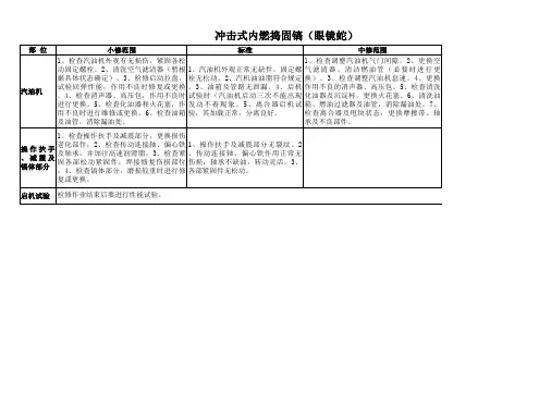
部 位 小修范围 1、检查汽油机外观有无损伤,紧固各松 动固定螺栓。2、清洗空气滤清器(暂根 据具体状态确定)。3、检修启动拉盘, 试验回弹性能,作用不良时修复或更换 。4、检查消声器、高压包,作用不良时 进行更换。5、检查化油器和火花塞,作 用不良时进行维修或更换。6、检查油箱 及油管,消除漏油处。 标准 1、汽油机外观正常无缺件,固定螺 栓无松动。2、汽机油油脂符合规定 。 3 、油箱及管路无泄漏。 4 、启机 试验时(汽油机启动三次不能出现 发动不着现象。 5 、 离合 器启 机试 验,其加载正常,分离良好。 中修范围 1 、检查调整汽油机气门间隙。 2 、更换空 气滤清器、清洁燃油管(必要时进行更 换)。 3 、检查调整汽油机怠速。 4 、更换 作用不良的消声器、高压包。5、检查清洗 化油器及沉淀杯,更换火花塞。6、清洗油 箱、燃油过滤器及油管,消除漏油处。7、 检查离合器及甩块状态,更换摩擦带、轴 承及不良部件。 标准 1 、汽油机外观正常无缺件,固定 螺栓无松动。 2 、汽机油油脂符合 规定。3、油箱及管路无泄漏。4、 启机试验时(汽油机启动三次不能 出现发动不着现象。 5 、离合器启 检查操作扶手及减震部分,更换损伤 老化部件;2、检查传动连接轴、偏心铁 操作扶手 及轴承,并加注高速润滑脂。3、检查紧 、减震及 固各部松动紧固件,焊接修复伤损部位 镐体部分 。4、检查镐体部分,磨损较重时进行修 复或更换。 启机试验 检修作业结束后要进行性能试验。
1 、操作扶手及减震部分无裂纹。 2 、传动连接轴、偏心铁作用正常无 伤损,轴承不缺油,转动灵活。 3、 各部紧固件无松动。
捣固机说明书(右型)

18锤捣固机(右型)产品说明书J7734.00SM太重技术中心2006年04月14 日编制:校核:审查:批准:DJ43/DC 捣固机产品说明书一.用途TZDJ43-DG-06I型捣固机是为4.3米捣固焦炉专门设计的配套设备,该型捣固机为18锤微移动捣固机,配好的原煤在装煤车上捣固成煤饼,再由装煤车送入炭化室的一种专用设备。
18锤捣固机分左右型,与转煤车对应布置, 左型捣固机配合左型装煤车,右型捣固机配合右型装煤车。
二.规格和性能设备主要技术性能(见表1)三、工作原理和结构特征TZDJ43-DG-06I型捣固机用来将配好的原煤在装煤车上捣固成煤饼,再由装煤车送入炭化室炼焦,它主要由微移动系统、凸轮机构、锤杆、停锤机构、变速机、导向装置、润滑系统、机架、从动轮机构组成。
现将捣固机的主要部件的结构简介如下:3.1、偏心轮装置偏心轮装置是捣固机的核心部分。
主要是通过一对内外齿轮啮合带动偏心轴转动,产生压紧力带动捣固锤运动。
其中压紧力由压紧装置中的两弹簧提供。
可单锤调节。
3.2、锤杆:锤杆的主体用工字钢焊制而成,锤杆两面各衬约14mm厚的摩擦材料,此种材料要求具有一定的韧性、耐摩性和一定的摩擦系数,锤杆和摩擦材料的连接方式采用粘接和铆接并用。
3.3、停锤机构:此停锤机构采用弧线偏心轮式机构,这种机构能保证在较大的加工误差情况下也能夹住锤杆。
3.4、传动齿轮箱:此传动齿轮箱采用封闭的四级齿轮传动方式,此种传动可传递较大的扭矩,同时结构紧凑合理,封闭的传动方式可增加设备在恶劣的环境下的使用寿命,此变速系统采用稀油电动润滑。
3.5、导向装置:导向装置分为上、中、下三组,上下导向均采用带轮缘导向辊轮的导向方式,导向轮可以选择钢材或尼龙材料。
使锤杆运行更趋于平稳。
3.6、润滑系统:3.6.1传动减速机用中负荷工业齿轮油220#,第一次加油后,15天到30天更换新油,以后每3-4个月换油一次,加油至油标中线为宜。
3.6.2各点采用单独的电动干油集中润滑,定期向润滑点加注润滑脂,此润滑方式运行可靠,减轻了工人的劳动强度。
D08-32捣固车常见故障排除与检查保养方法浅层分析___________工程机械1301 (1)
D08-32捣固车常见故障排除与检查保养方法浅层分析***名:***学号:*******专业班级:工程机械1301***师:***摘要中国铁路事业蓬勃发展,随着第六次铁路大提速在全国个主要干线上的展开,我国已迈进了高速铁路时代。
高时速就意味着要有更高的安全保障,而线路作为铁路的一个重要环节,其质量的好坏直接关系到人民的安全问题,D08-32捣固车是保证铁道线路质量的重要养路设备。
我国大型养路机械已有近40年的历史,主要靠引进外国技术生产。
面对这铁路提速后对线路质量的更高要求,提高养路机械的保养与故障排除就相当重要。
市场的需求促进技术和产品的消化吸收和创新。
本文就是针对D08-32捣固车的故障排除与保养分析进行了研究与总结。
将D08-32捣固车的一些故障与如何保养进行详细说明,帮助大家有效的对捣固车可能出现的故障进行预防排除。
关键词:捣固车;故障排除;保养分析目录摘要..................................................................................................... 错误!未定义书签。
引言..................................................................................................... 错误!未定义书签。
1 绪论 (1)1.1 我国大型养路机械的发展及现状 (1)1.1.1我国大型养路机械的发展历程 (1)1.1.2我国大型养路机械的现状........................................................ 错误!未定义书签。
1.1.2.1我国捣固车发展历程 (5)1.1.3.我国养路机械的发展前景 (6)2捣固车简介 (7)2.1 捣固车的整体性能参数简介 (7)2.2 捣固车的工作装置........................................................................................................ .92.2.1 捣固装置的组成..................................................................................................... .92.2.2 捣固装置的原理 (9)2.2.3起拨道装置的组成 (9)2.3作业程序及技术要求 (10)3捣固车故障排除的分析 (11)3.1捣固车的主要故障 (11)3.1.1柴油机故障 (11)3.1.1.1电气故障 (11)3.1.1.2机械故障 (12)3.1.1.3油路故障 (13)3.1.2起道系统故障............................................................................ 错误!未定义书签。
Model 6360 6361 救急车床垫固定器产品说明书

Model 6360/6361Ambulance Cot FastenerINSTALLATION/OPERATION INSTRUCTIONSFor Parts or Technical Assistance1–800–784–4336Table of Contents. . . . . . . . . . . . . . . . . . . . . . . . . . . . . . . . . . . . . . . . . . . . . . . . . . . . . . . . . . . . . . . . . . . . . . . . . . . . . . Introduction2. . . . . . . . . . . . . . . . . . . . . . . . . . . . . . . . . . . . . . . . . . . . . . . . . . . . . . . . . Warning / Caution / Note Definition2Warranty. . . . . . . . . . . . . . . . . . . . . . . . . . . . . . . . . . . . . . . . . . . . . . . . . . . . . . . . . . . . .Obtaining Parts and Service3. . . . . . . . . . . . . . . . . . . . . . . . . . . . . . . . . . . . . . . . . . . . . . . . . . . . . . . .Supplemental Warranty Coverage3 . . . . . . . . . . . . . . . . . . . . . . . . . . . . . . . . . . . . . . . . . . . . . . . . . . . . . . . . . . . . . . . . . . . .Return Authorization4. . . . . . . . . . . . . . . . . . . . . . . . . . . . . . . . . . . . . . . . . . . . . . . . . . . . . . . . . . . . . . . . .Freight Damage Claims4 Installing Floor Mounted Cot Fastener. . . . . . . . . . . . . . . . . . . . . . . . . . . . . . . . . . . . . . . . . . . . .Positioning of the Antler Floor Mounting Plates5, 6. . . . . . . . . . . . . . . . . . . . . . . . . . . . . . . . . . . . . . . . . . . . . . .Positioning of the Rail Floor Mounting Plates6Fastener Attachment7 . . . . . . . . . . . . . . . . . . . . . . . . . . . . . . . . . . . . . . . . . . . . . . . . . . . . . . . . . . . . . . . . . . . Installing Wall Mounted Cot Fastener. . . . . . . . . . . . . . . . . . . . . . . . . . . . . . . . . . . . . . . . . . . . .Positioning of the Antler Floor Mounting Plates8, 9 Positioning of the Rail Wall Mounting Plate9. . . . . . . . . . . . . . . . . . . . . . . . . . . . . . . . . . . . . . . . . . . . . . . . .. . . . . . . . . . . . . . . . . . . . . . . . . . . . . . . . . . . . . . . . . . . . . . . . . . . . . . . . . . . . . . . . . . .Fastener Attachment10 Cot Fastener Operation11, 12 . . . . . . . . . . . . . . . . . . . . . . . . . . . . . . . . . . . . . . . . . . . . . . . . . . . . . . . . . . . . . . .Assembly Drawings and Parts Lists. . . . . . . . . . . . . . . . . . . . . . . . . . . . . . . . . . . . . . . . . . . . . . . . . . . . .Wall Mounted Cot Fastener Assembly13. . . . . . . . . . . . . . . . . . . . . . . . . . . . . . . . . . . . . . . . . . . . . . . . . . . .Floor Mounted Cot Fastener Assembly14IntroductionINTRODUCTIONThis manual is designed to provide instructions for the installation, usage and maintenance of the Stryker 6360 Floor Mounted Cot Fastener and the 6361 Wall Mounted Cot Fastener. The Stryker 6360 and 6361 cot fasteners are not designed for any purpose other than to restrict movement of an ambulance cot being transported in the patient compartment of an ambulance under normal conditions. Usage of these products in any other way becomes the complete responsibility of the owner/user. An independant test lab has determined that the 6360 and 6361 will hold an ambu-lance cot secure in the event of an accident as defined in AMD specification 004. Caution must be used at all times during placement of the cot into the ambulance.WARNING / CAUTION / NOTE DEFINITIONThe words WARNING, CAUTION and NOTE carry special meanings and should be carefully reviewed.WARNINGThe personal safety of the patient or user may be involved. Disregarding this information could result in injury to the patient or user.CAUTIONThese instructions point out special procedures or precautions that must be followed to avoid damaging the equipment.NOTEThis provides special information to make maintenance easier or important instructions clearer.Limited Warranty:Stryker Medical Division, a division of Stryker Corporation, warrants to the original purchaser that its products should be free from defects in material and workmanship for a period of one (1) year after date of delivery. Stryker’s obligation under this warranty is expressly limited to supplying replacement parts and labor for, or replacing , at its option , any product which is, in the sole discretion of Stryker, found to be defective. Stryker warrants to the original purchaser that the frame and welds on its products will be free from structural defects for as long as the original purchaser owns the product. If requested by Stryker, products or parts for which a warranty claim is made shall be returned prepaid to Stryker’s factory. Any improper use or any alteration or repair by others in such manner as in Stryker’s judgement affects the product materially and adversely shall void this warranty. No employee or representative of Stryker is authorized to change this warranty in any way. This statement constitutes Stryker’s entire warranty with respect to the aforesaid equipment. STRYKER MAKES NO OTHER WARRANTY OR REPRESENTATION, EITHER EXPRESSED OR IMPLIED, EXCEPT AS SET FORTH HEREIN. THERE IS NO WARRANTY OF MERCHANTABILITY AND THERE ARE NO WARRANTIES OF FITNESS FOR ANY PARTICULAR PURPOSE. IN NO EVENT SHALL STRYKER BE LIABLE HEREUNDER FOR INCIDENTAL OR CONSEQUENTIAL DAMAGES ARISING FROM OR IN ANY MANNER RELATED TO SALES OR USE OF ANY SUCH EQUIPMENT.To Obtain Parts and Service:Stryker products are supported by a nationwide network of dedicated Stryker Field Service Representatives. These representatives are factory trained, available locally, and carry a substantial spare parts inventory to minimize repair time. Simply call your local representative, or call Stryker Customer Service at (800) 327–0770.Supplemental Warranty Coverage:Stryker has developed a comprehensive program of extended warranty options designed to keep your equip-ment operating at peak performance at the same time it eliminates unexpected costs. We recommend that these programs be activated before the expiration of the new product warranty to eliminate the potential of additional equipment upgrade charges. Stryker offers the following Supplemental Warranties:Extended (Parts and Labor)S All replacement parts (excluding mattresses and consumable items)S Labor and travel for all scheduled and unscheduled callsS Biannual Preventive Maintenance Inspections and repairsS JCAHO paperwork for preventive maintenanceS Priority Emergency ServiceStandard (Labor Only):S Labor and travel for all scheduled and unscheduled callsS Biannual Preventive Maintenance Inspections and repairsS JCAHO paperwork for preventive maintenanceS Priority Emergency ServiceBasic (Parts Only):S All replacement parts (excluding mattresses and consumable items)S Priority Emergency ServicePlease call your local representative, or call (800) 327–0770 for further informationReturn Authorization:Merchandise cannot be returned without approval from the Stryker Customer Service Department. An autho-rization number will be provided which must be printed on the returned merchandise. Stryker reserves the right to charge shipping and restocking fees on returned items.SPECIAL, MODIFIED, OR DISCONTINUED ITEMS NOT SUBJECT TO RETURN.Damaged Merchandise:ICC Regulations require that claims for damaged merchandise must be made with the carrier within fifteen (15) days of receipt of merchandise. DO NOT ACCEPT DAMAGED SHIPMENTS UNLESS SUCH DAMAGE IS NOTED ON THE DELIVERY RECEIPT AT THE TIME OF RECEIPT. Upon prompt notification, Stryker will file a freight claim with the appropriate carrier for damages incurred. Claim will be limited in amount to the actual replacement cost. In the event that this information is not received by Stryker within the fifteen (15) day period following the delivery of the merchandise, or the damage was not noted on the delivery receipt at the time of receipt, the customer will be responsible for payment of the original invoice in full.Claims for any short shipment must be made within thirty (30) days of invoice.Positioning of the Antler Floor Mounting Plates1.Determine the desired position of the cot inside the vehicle allowing for proper clearance around the cot. NOTEFederal ambulance specifications regarding aisle width and attendant seating may affect positioning of the mounting brackets. If specifications do not apply, the installer should be certain there is adequate clearance for proper patient access, traction splint projection, rear door closure, etc.ing the dimensions shown in View 1 below, locate and drill the two points where the antler floor plateswill attach. Recess two 1” x 2 1/2” x 9/16” deep openings into the floor centered over the plate locating points as shown in View 2 below.VIEW 1VIEW 2Positioning of the Antler Floor Mounting Plates (Continued)ing two 3/8” diameter socket head cap screws (not supplied), anchor each antler floor plate into the recessed openings with the counter –bored holes facing up as shown in View 2 on page 5. Steel backing plates (4” x 6” x 3/8”) are required for added support as shown in View 3 below (not supplied).CAUTIONDo not use screws smaller than the 3/8” diameter specified to anchor any of the floor plates.Positioning of the Rail Floor Mounting Platesing the dimensions shown in View 1 on page 5, locate and drill the four points where the rail support bracket floor plate will attach. Recess one 2 1/2” x 5” x 9/16” deep opening into the floor centered over the locating points as shown in View 4 below.ing four 3/8” diameter socket head cap screws (not supplied), anchor the floor plate into the recessed opening with the counter –bored holes facing up as shown in View 4 below. The keyhole should be towards the front of the vehicle. A steel backing plate (6” x 9” x 3/8”) is required for added support as shown in View 3 below (not supplied).NOTEOne set of additional floor plates is supplied to allow alternate positioning anywhere on the patient compart-ment floor. Cot space requirements are the same as shown in View 1 on page 5. Repeat the above proce-dure to install the alternate position floor plates.VIEW 4VIEW 3Fastener AttachmentVIEW 7VIEW 6VIEW 56.Position the antler over the floor plates and fasten with the red knobs as shown in View 5. The additionalmounting holes in the antler bracket are used to position the antler for the model 6361 wall mounted cot fastener system.7.Position the rail support bracket over the floor mounting plate. Insert the socket head screw into the key-hole and slide the assembly forward until the hole in the bracket lines up with the tapped hole in the floor plate. Fasten securely using one of the red knobs as shown in View 6.8.Position the rail assembly on the support bracket and attach the rail using the rail clamp and four 5/16–18x 2” socket head cap screws provided as shown in View 7.NOTEThe strength of any fastener mounting installation should be confirmed by the installer’s own test procedure before placing in service.Positioning of the Antler Floor Mounting Plates1.Determine the desired position of the cot inside the vehicle allowing for proper clearance around the cot. NOTEFederal ambulance specifications regarding aisle width and attendant seating may affect positioning of the mounting brackets. If specifications do not apply, the installer should be certain there is adequate clearance for proper patient access, traction splint projection, rear door closure, etc.ing the dimensions shown in View 1, locate and drill two holes to attach the antler floor plates. Recesstwo 1” x 2 1/2” x 9/16”deep openings into the floor centered over the locating holes as shown in View 2.VIEW 2VIEW 1Positioning of the Antler Floor Mounting Plates (Continued)ing two 3/8” diameter socket head cap screws (not supplied), anchor the floor plates into the recessed openings with the counter –bored holes facing up as shown in View 2 on page 8. Steel backing plates (4” x 6” x 3/8”) are required for added support as shown in View 3 below (not supplied).CAUTIONDo not use screws smaller than the 3/8” diameter specified to anchor the floor plates.NOTEOne set of additional floor plates is supplied to allow alternate positioning anywhere on the patient compart-ment floor. Cot space requirements are the same as shown in View 1. Repeat the above procedure to install the alternate position floor plates.Positioning of the Rail Wall Mounting Plateing the dimensions shown in View 1 on page 8, locate and drill the four points where the rail wall mount-ing bracket will attach.ing four 5/16” diameter socket head cap screws (not supplied), anchor the wall bracket as shown in Views 4 and 5 below. A steel backing plate (6” x 9” x 3/8”) is required for added support as shown in View 4 (not supplied).CAUTIONDo not use a screw smaller than the 5/16”diameter specified to anchor the wall plate.VIEW 3VIEW 4VIEW 5Installing Wall Mounted Cot FastenerFastener AttachmentVIEW 66.Position the antler over the floor plates and fasten with the red knobs as shown in View 6. The additionalmounting holes in the antler bracket are used to position the antler for the model 6360 floor mounted cot fastener system.VIEW 77.Position the rail assembly on the wall mounting bracket as shown in View 7. Attach the rail using the railclamp and four 5/16–18 x 2” socket head cap screws and nuts provided.NOTEThe strength of any fastener mounting installation should be confirmed by the installer’s own test procedure before placing in service.Adjustment And Operation1.Adjustment of the rail assembly may be required to compensate for slight variation in the position of the cot post.Adjustment is made vertically by removing the rail clamp (A) and rail assembly (B) from the existing mount-ing holes and moving it to the set of holes that will align the clamp jaws (C) with the post on the cot. Position the rail assembly front/back. Adjustment is limited to 1/2” front/back or 1” total movement. Do not overlap the adjustment limit label (D) on the rail assembly. When adjustment is complete, rotate the rail assembly so the jaws are parallel with the floor and tighten the mounting screws until the rail clamp is drawn firmly against the support bracket.WARNINGTo prevent the cot frame from coming out of the rail jaws, the space between the rail clamp and the rail station-ary jaw must NEVER exceed 1”. T o prevent the cot from coming out of the rail jaws and causing possibleinjury to the patient or user, the rail clamp must not overlap the red adjustment limit label on the rail tube.ABDECAdjustment Limit Label2.To operate the fastener, push the rail handle (E) forward until the release button engages and the jaws lock in the open position.WARNINGThe fastener closes with a strong spring action. T o avoid injury, DO NOT use hand or fingers to depress the release button when the rail jaws are open.Adjustment And Operation (Continued)3.Guide the cot into the fastener at a slight angle, as shown above, engaging the loading wheels with theantler. Move the foot end of the cot sideways until the cot post enters the rail jaws and presses the release button. The rail jaws will close, locking the cot securely in position.4.Cot bedding may prevent the attendants from seeing the rail jaws close around the cot post. The properlyinstalled and adjusted fastener closes with a ”positive” sound and feel that serves as a good indicator of proper engagement. Check for positive engagement by grasping the cot frame and pushing/pulling with sufficient force to disengage the cot if the fastener jaws are not completely closed.5.To remove the cot, use one hand to actuate the push handle forward, far enough for the jaws to releasethe cot post. With the other hand, grasp the cot and roll it away from the rail.WARNINGThe fastener closes with a strong spring action. T o avoid injury, DO NOT use hand or fingers to depress the release button when the rail jaws are open.Assembly part number 6361–30–10GHHGC BADEFItemPart No.Part NameQty.A 6361–30–12Wall Mounting Bracket 1B 6360–30–18Rail Clamp1C 4–71Soc. Hd. Cap Screw 4D 16–36Hex Nut4E 6360–20–10Rail Assembly 1*F 6360–30–23Antler Weldment 1G 6360–30–31Knob Assembly 2H6360–30–12Small Floor Plate2* The rail assembly is not designed to be a repairable item. It must be purchased as a complete assembly.Individual components are not available for order.EFHHFB A FGDCJAssembly part number 6360–30–10ItemPart No.Part NameQty.A 6360–30–18Rail Clamp1B 4–250Soc. Hd. Cap Screw 4C 16–36Hex Nut4D 6360–20–10Rail Assembly 1*E 6360–30–23Antler Weldment 1F 6360–30–31Knob Assembly 3G 6360–30–11Large Floor Plate 2H 6360–30–12Small Floor Plate 4J6360–30–24Rail Support Bracket1* The rail assembly is not designed to be a repairable item. It must be purchased as a complete assembly.Individual components are not available for order.DH 6/95 6360–90–10 REV A6300 Sprinkle Road, Kalamazoo, MI 49001–9799 (800) 327–0770。
09-32捣固车安全系统分析
09-32捣固车安全系统分析09-32捣固车与08系列捣固车相比较,更加科学更具先进性,由步进式捣改进为连续式捣固,较较明显地改善了及操作人员的工况,减经了操纵人员的疲劳强度,作业效率比08-32提高30%以上。
09-32捣固车的结构、工作原理是在08-32捣固车的基础上进行了改进,运用了一些新的技术,如增加了捣固系统的卫星期三小车装置曲线要素的自动检测系统。
安全保障系统等,通过对09-32捣固车一年多的使用,现就对09-32安全保障系统进行简单分析。
09-32捣固车增加安全保障系统,提高了行车、作业安全系数,防止了因操作人员的误操作导致设备以及行车故障。
为安全生产提供了有效的保证。
一、主要组成B95箱的EL-T6031控制电路板、D1-D6继电器,B2箱EL-5533控制电路板(俗称看门狗)及IS841电磁阀。
二、基本功能需保护状态时,安全保障系统电路控制电磁阀动作,使主风缸送来的气体经进压力调整后进入制动风缸,对单机施加制动使设备不能运行和作业,发挥保护作用,不需保护时工作正常。
三、工作原理1、正党情况下,当总风缸压力达到3.8bar时,单机自动制动。
正常情况下,变矩器的11b24、5b34钥匙开关在分离位,液压系统未建立压力,当总风缸压力达到3.8bar时,即使用单独制动阀施加制动,制动缸仍处于使用独制动阀施加制动,制动缸仍处于制动状态。
控制电路工作过程是继电器95d5、95d6得电吸合,自保继电器95d4得电吸合,当95d4~95d6继电器得电工作后,95d1、95d2继电器得电常开触点吸合,沟通主电源供电回路,但95d3继电器未得电,IS电磁阀不动作控制风路对制动缸充风制动。
控制电路工作过程:电源201-停机按钮4d23/1端-停机按钮4d23/2端-停机按钮2d1/1端-停机按钮2d1/2端-95d6继电器-地,95d6继电器得电动作。
电源经201-停机按钮4d23/11停机按钮4d23/12-停机按钮2d1/11-停机按钮2d1/12-Si24端子-95d1继电器常闭触点12、11-95d2继电器常闭触点12、1195d4继电器-地,95d4继电器得电动作,95d4继电器吸合后通过自身已闭合的触点9、6自保。
西屋制动(Wabtec)机车产品
D77/D78
D77/D78
D77/D78
最大速度(公称) 50mph
70mph
70mph
持续牵引力
55,000ibs
55,000ibs
82,000ibs
启动牵引力
85,000ibs
85,000ibs
128,000ibs
重量(公称)
270,000ibs
277,000ibs
390,000ibs
长度
59′ 2″
第 45 页
热交换器 ·水冷散热器 ·各种其他部件
第 51 页
橡胶产品
第 55 页
服务 ·培训 ·PTC 支持 ·空压机 ·牵引电机 ·机车服务 ·气动设备 ·电气设备
第 57 页
相关企业的信息
封底
1
机车说明
ECP 17.SCD 电源 18.VCD 电源 19. 车辆地址模块 20. 列头列尾单元
PTC 21. 截断塞门 22.ETMS 显示 23. 切除柜 mlink 25. 导航传感器 26. 列车管理计算机
各种其他部件 27. 司机室无线电 28. 厕所 29. 冰柜 30. 风化材料 31. 车轮 32. 弹簧 33. 密封圈 34. 轴信号发生器 35. 闸瓦 36. 控制系统 37. 牵引电机 38. 牵引电机碳刷架
气动设备
空压机
3CDTM 压缩机升级
集成的后端冷却器 ·高效的,符合成本效益的,免维护的方法使制动系统压缩空气中的
水汽沉淀下来
恒温控制中间冷却器 ·为电机驱动起动和停止的空压机设计 ·通过使中间冷却器维持在一个稳定温度消除冷凝在油中的水
当前眼镜蛇捣固机使用和保养几点注意事项
当前眼镜蛇捣固机使用和保养几点注意事项北京安通伟业铁路工务技术有限公司周保庆俞京科北京局自2004年开始引进瑞典阿特拉斯柯普柯BEREMA有限公司生产的眼镜蛇TT型捣固机,用于京沪、京广、京秦、京山等干线的线路、道岔捣固整修作业,目前全局已有637台。
由于该机具有作业效率高、效果好、操作简便的优点,是我局使用的单镐捣固机中最理想的机型。
同时又具有价值较高、保养要求严格的特点。
因此加强此项工作管理显得十分重要。
近来,我们对天津、北京、石家庄、三家店等段使用的112台眼镜蛇捣固机维修服务,结合现场使用情况,对损坏的原因进行分析并提出建议如下。
原因损坏占65%。
二、通过上述原因分析,我们认为应加强如下几方面的工作。
1、对二冲程汽机油的质量及配比一定要严格把关。
通过现场的维修发现,使用者未按说明书要求,使用了非正规厂家生产非标准牌号的二冲程汽机油,造成了发动机曲轴连杆烧死,活塞、缸筒拉伤。
而坚持正确使用二冲程汽机油很少发生上述情况。
燃油配比也尤为重要。
汽、机油正确配比为1∶50,在加油配比时应使用配比壶。
2、加强对眼镜蛇捣固机的操作培训、日常保养和维护段要定期组织对操作人员进行培训,操作人员经培训后再上道作业。
使用眼镜蛇捣固机的领工区、工区应设专人负责严格按使用操作说明书对机器进行保养。
定期检查和更换滤芯,定期检查齿轮箱和夯锤润滑油位,适时添加机油。
段工厂应设有经过培训的专业修理人员,定期对领工区、工区的眼镜蛇捣固机进行巡检和修理,指导现场人员正确使用。
3、有三个部位要特别注意。
首先,是空滤器上盖使用时要上紧,不得松动和破损。
否则会加快发动机曲轴连杆、活塞、缸筒的磨损。
其次,散热风扇和风扇聚风外罩不得破损,否则发动机曲轴连杆、活塞会因散热不良而损坏。
因此上述两个部位损坏,务必停机修复后再用。
再次,更换镐钎务必停机进行,否则会损坏夯锤系统。