REX仪器软件操作说明书
REX-C100 系列 模拟式温度控制器 说明书

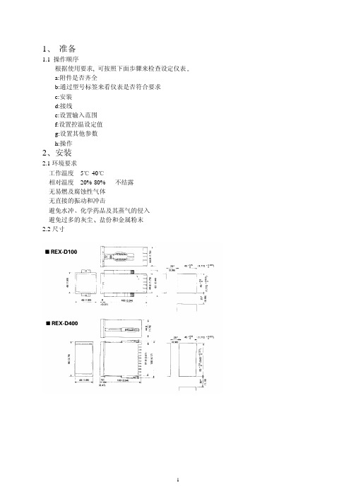
Notes:Make sure that this Instruction Manual is always readily available to personnel who use the REX-C100 series.The contents of the Instruction Manual are subject to change without notice. If you have any questions regarding the manual,contact one of our sales people, our nearest sales office, or the place where you have purchased the controller.1.PRODUCT CHECKCheck whether the delivered product is as specified by referring to the following model code list.OModel codeC100 QQQ - Q ~ QQÎ Ï Ð Ñ Ò ÓÎControl actionÓSecond alarm [ALM2]F : PID action [Reverse action]N : No second alarmD : PID action [ Direct action]A : Deviation high alarm *2B : Deviation low alarm *2ÏInput typeC : Deviation high / low alarm *2See input range table “Model code” page 9D : Band alarmE : Deviation high alarm *3ÐInput rangeF : Deviation low alarm *3See input range table “Model code” page 9G : Deviation high / low alarm *3H : Process high alarm *2ÑControl output [OUT]J : Process low alarm *2M : Relay contact K : Process high alarm *3V : Voltage pulseL : Process low alarm *38 : Current 4 to 20mA DCP : Heater break alarm (CTL-6)G : Trigger (for triac driving) *1S : Heater break alarm (CTL-12)R : Control loop break alarm *4ÒFirst alarm [ALM1]N : No first alarm*1When control output is trigger output A : Deviation high alarm *2for triac driving, only the first alarm isB : Deviation low alarm *2available.C : Deviation high / low alarm *2*2Without hold action.D : Band alarm*3With hold actionE : Deviation high alarm *3*4As control loop break alarm, only eitherF : Deviation low alarm *3the first alarm or second alarm is G : Deviation high / low alarm *3selected.H : Process high alarm *2J : Process low alarm *2CConfirm that power supply voltage is alsoK : Process high alarm *3the same as that specified when ordering.L : Process low alarm *3R : Control loop break alarm *4Accessories C Mounting brackets (2 pcs.)CInstruction manual(1 copy)REX-C100SERIESINSTRUCTION MANUALFig. 1Fig. 22.MOUNTING •DimensionsUnit : mm (inch)* Dimensions in inches are shown for reference•Mounting proceduresThickness of panel board:1 to 5mm or 5 to 9mm (0.04 to 0.20 inch or 0.20 to 0.35 inch)uWhen the controllers are mounted on panel with 1 to 5mm in thickness ÎMake a rectangular cutout corresponding to thenumber of controllers to be mounted on panel by referring to the panel cutout dimensions.ÏSince the mounting brackets are already installed onthe controller, insert the controller into the panel from the panel front without removal of the brackets (Fig. 1).uWhen the controllers are mounted on panel with 5 to 9m in thickness ÎRemove the mounting brackets from the controllerwith a slotted screwdriver.ÏEngage each mounting bracket with holes markedwith “5.9" on the housing (Fig. 2) and then insert the controller into the panel from the panel front.OCautions for mountingMo untingbracketAvoid the following location where the controller is mounted.C Location where ambient temperature is more than 50E C (122E F) or less than 0E C (32E F).C Location where humidity is high.C Location where corrosive gas is generated.C Location where strong vibration and shock exist.C Location where flooding and oil splash exist.C Location where much dust exists.CLocation where inductive disturbance is large and otherlocation where bad influence is exerted on electric instrument.3.WIRING•Rear terminalsNotes1.Terminals which are not used according to the controller type are all removed.2.For thermocouple input, no metal piece is attached to terminal No. 10. Instead, the temperature compensationelement in the internal assembly is projected through a hole at terminal No. 10.Do not damage the above temperature compensation element when the internal assembly is removed from the case.O Cautions for wiring(1)Conduct input signal wiring away from instrument, electric(3)For wiring, use wires conforming to domesticequipment power and load lines as such as possible to avoid standard of each country.noise induction.(4)About 5 to 6 sec. are required as the(2)Conduct instrument power wiring so as not to be influenced preparation time of contact output duringby noise from the electric equipment power.power ON. Use a delay relay whenthe outputIf it is assumed that a noise generation source is located near line, is used for an external interlock circuit.the controller and the controller is influenced by noise, use anoise filter (select the filter by checking instrument power(5)The figures below show the REX-C100 circuit supply voltage.)configuration. When connecting wires, notethat the power, input, MCU and output circuitsC Sufficient effect may not be obtained depending on the are isolated independently, while the inside offilter. Therefore, select the filter by referring to its the input and outputcircuits are not isolated.frequency characteristic, etc.ÎFor instrument power wiring, if it is assumed that noiseexerts a bad influence upon the controller, shorten thedistance between twisted power supply wire pitches.(The shorter the distance between the pitches, the moreeffective for noise reduction).ÏInstall the noise filter on the panel which is alwaysgrounded and minimize the wiring distance between thenoise filter output side and the controller power terminals.Otherwise, the longer the distance between output sideand instrument power terminals, the less effective for REX-C100 circuit configurationnoise.ÐDo not install fuses and / or switches on the filter outputsignal since this may lessen filter effect.WIRING AND NAME OF PARTS•Wiring exampleREX-C100F GG-M*-~2N-HA OF PARTSÑSet-value increment keyC Used when the number needs to be increasedfor set-value change.ÒMeasured-value (PV) display unit [Green]C Displays measured-value (PV)C Displays a parameter symbol in the parametersetting mode.ÓSet-value (SV) display unit [Orange]C Displays set-value (SV)C Displays set-value corresponding to theparameter symbol displayed on the measured-value (PV) display unit.ÎSet (SET) keyC The set-value thus changed is enteredÔControl output (OUT) lamp [Green]C Parameters in the parameter setting mode are C Lights up when the control output is turnedON.selected in due order.C Can select PV / SV display mode, SV settingÕAuto-tuning (AT) lamp [Green]mode, and parameter setting modes.C Flashes during auto-tuning.ÏSetting digit shift keyÖFirst alarm (ALM1) lamp [Red]C Used when the cursor (brightly lit) is moved to C Lights up when the first alarm is turned ON.the digit whose number needs to be changed for C When a control loop break alarm (LBA) is set-value change.selected as the first alarm, this lamp lights up.ÐSet-value decrement key×Second alarm (ALM2) lamp [Red]C Used when the number needs to be decreased C Lights up when second alarm is turned ON.for set-value change.C When either a heater break alarm (HBA) orcontrol loop break alarm (LBA) is selected asthe second alarm, this lamp lights up.5.OPERATION•Calling-up procedure of each mode:Press the key.Input type code / input range displayThis controller, with the power turned ON, displaysautomatically the input type code on the measured-value (PV)display unit and the input range, on the set-value (SV) displayunit, respectively.Example : For a controller with the K thermocouple inputtype and input range from 0 to 1372E C.ÎDisplays the input type code.: Indicates input abbreviation.unit. ( : E F)input type code table).ÏDisplays the input range.< Input type code >Code Input Type Code Input typeRSBW5Re/W26RePLIIPt100JPt100PV / SV display modeC Displays measured-value (PV) on the measured-value(PV) display unit and set-value (SV) on the set-value (SV)display unit. Usually the control is set to this modeexcepting that the set-value (SV) and/or the parameter set-value are changed.PV / SV display modeC Pressing the key lights the least significant digit onvalue (SV).In order to register the value whose setting was changed,always press the key after the value is changed.sec. in the PV / SV display or SV setting mode, thecontroller is set to the parameter setting mode.C Parameters in the parameter setting mode changes in dueorder every time the key is pressed (See page 6).and keys are pressed.C In order to register the value whose setting was changed,press the key after change to shift to the nextsec.•When no key is operated for more than 1 minute.•Parameter typesThe following parameter symbols are displayed one by one every time the key is pressed.Current transformer input (CT)Setting is not possible.Set heater break alarm value byreferring to this value.Display input value from thecurrent transformerCTSecond alarm Set alarm set-value of second alarm.AL2Control loopbreak alarm (LBA)0.0 to 200.0 min.Set control loop break alarmset-value.Cannot be set to “0.0".8.0LbAAuto-tuning (AT)0 : Auto-tuning end or stop1 : Auto-tuning startTurns the auto-tuningON/OFF.ATUIntegral time (I)1 to 3600 sec.Eliminates offset occurringcontrol is performed. I actionturns OFF with I set to “0".240IAnti-reset windup (ARW)1 to 100% of proportional band.Prevents overshoot and/orundershoot caused by integralaction. I action turns OFFwith this action set to “0".100ArSet data lock 0100 : No set data locked (Allparameters changeable)0101 : Set data locked (All parametersnot changeable)0110 : Only the set-value (SV) ischangeable with the set data locked.Performs set data changeenable / disable.0100LCK* The second alarm (or first alarm), heater break alarm, control loop break alarm parameter symbols are not simultaneously displayed. * Heater break alarm is not available on a current output.C Parameter setting procedure Setting set-value (SV)Following is an example of setting the set-value (SV) to 200E C. (PV : 30E C)Î Set to the set modeÏ Shift of the digit brightly litÐ Set-value increase or decrease ÑSet-value entryPress the key to Press the key to shift Press the key to set “2".After finishing the setting,enter the SV setting mode.the digit which lights brightlypress thekey. All ofController returns to the PV/SV display mode.Example : When a temperature of 199E C is changed to 200E C.Set-value increase or decreasePress the key to shift the digit brightly lit to the least significant digit. Press the key to change “9" to “0", therebyobtaining 200E C. The same applies to set-value decrease.Example : For changing 200 to -100.Minus (-) value settingPress the key to shift the digit brightly lit to the hundreds digit. Press the key to decrement figures in order of÷ 0 ÷ -1.Setting parameters other than set-value In the PV/SV display modeIn the parameter setting modeKey operational cautions CFor this controller, the value whose setting was changed is not registered. It is registered for the first time it is shifted to the next parameter by pressing the key.setting mode, set data lock is activated.In this case, change the “” parameter set-value to “0100".the parameter setting mode.Press thekey by the required number of times untilkey after the setting is finished in the parameters).When no parameter setting is required, return the controller to the PV/SV display mode.¬Pay attention to the following when the parameters described below are set.Auto-tuning (AT)C Prior to starting the auto-tuning function, end all the parameter settings other than PID and control loop break alarm(LBA).Heater break alarm (HBA)C Set heater break alarm set-value to a value about 85% current transformer input value. However, when power supplyvariations are large, set the alarm to a slightly smaller value.In addition, when two or more heaters are connected in parallel, set the alarm to a slightly larger value so that it is activated even with only one heater is broken. (However, within the value of a current transformer input value).C When the heater break alarm set-value is set to “0.0" or the current transformer is not connected, the heater breakalarm is turned ON.Control loop break alarm (LBA)C Usually set the set-value of the LBA to a value twice the integral time (I).O Set data locking procedureThis controller is provided with a set data locking function which disables each set-value change by the front key and also the auto-tuning function. Use this function for malfunction prevention at the end of each setting.C Press the key by the required number of(PV) display unit.C Press the , and keys to set the•Display at error occurrence< Heater break alarm >Display CauseMeasure(Lights)C Controlled object trouble (No power supply,incorrect wiring, etc).C Sensor trouble (Sensor disconnected, shorted, etc).C Actuator trouble (Weld relay contact, incorrectwiring, relay contact not closed, etc).C Output circuit trouble (Weld internal relay contact,relay contact not opened or closed, etc).C Input circuit trouble (The measured-value does notchange even if input changes, etc).Control system check(Error cause cannot bespecified)Check whether there is no effectby disturbances (Other heatsource, etc).LBA set time check< Overscale, Underscale >Input type Input display rangeTCK-30 to +1372E C -30 to +2502E F J-30 to +1200E C -30 to +2192E F R, S-30 to +1769E C -30 to +3216E F B-30 to +1820E C -30 to +3308E F E-30 to +1000E C -30 to +1832E F T-199.9 to +400.0E C -199.9 to +752.0E F N-30 to +1300E C -30 to +2372E F PLII-30 to +1390E C -30 to +2534E F L-30 to +800E C -30 to +1600E F U-199.9 to +600.0E C -199.9 to +999.9E F W5Re/W26Re-30 to +2320E C -30 to +4000E FRTDPt100JPT100-199.9 to +649.0E C Pt100-199.9 to +999.9E F。
REX521使用手册及调试技巧,依据多年使用,现场经验总结。

Protection Relay REX 521Operator’s Manual3REX 521Issued:29.11.2001Version:E/04.06.2004We reserve the right to change data without prior notice.Protection Relay Operator’s Manual Contents1.About this manual (5)1.1.Copyrights .....................................................................................51.2.Trademarks ...................................................................................51.3.General .........................................................................................51.4.Abbrevitations ...............................................................................61.5.Related documents .......................................................................61.6.Document revisions .. (7)2.Safety information (7)3.Introduction (8)3.1.REX 521 protection relay (8)4.Instructions (9)4.1.HMI features (9)4.1.1.Push-button functions (11)4.1.2.Selecting language (12)4.1.3.Passwords (13)4.1.4.Display backlight (13)4.1.5.Display contrast (13)4.1.6.Display test (14)4.1.7.Selecting primary values (14)4.1.8.Optically isolated serial communication port (14)4.2.Menu chart (15)4.2.1.Measurement menu (16)4.2.2.Event menu (17)4.2.3.Manual control (18)4.2.3.1.Local/Remote position selection (18)4.2.3.2.Controlling breaker (19)4.2.4.Setting parameters (21)4.2.5.Setting bit masks (21)4.3.Indication messages (22)4.3.1.Protection indications (22)4.3.2.Self-supervision (23)4.3.3.Condition monitoring indication (24)4.4.LED indicators (25)4.4.1.Green indication LED (READY) (25)4.4.2.Yellow indication LED (START) (25)4.4.3.Red indication LED (TRIP) (25)4.5.Alarm LEDs (26)4.5.1.Alarm LED 1-8 (26)1MRS 751107-MUMREX 521Protection Relay1MRS 751107-MUMOperator’s Manual5.Test mode (27)5.1.I/O test (27)5.2.IRF test (27)5.3.Function block test (28)6.Index (29)41MRS 751107-MUMProtection Relay Operator’s Manual REX 52151.About this manual 1.1.Copyrights The information in this document is subject to change without notice and should not be construed as a commitment by ABB Oy. ABB Oy assumes no responsibility for any errors that may appear in this document.In no event shall ABB Oy be liable for direct, indirect, special, incidental or consequential damages of any nature or kind arising from the use of this document, nor shall ABB Oy be liable for incidental or consequential damages arising from use of any software or hardware described in this document.This document and parts thereof must not be reproduced or copied without written permission from ABB Oy, and the contents thereof must not be imparted to a third party nor used for any unauthorized purpose.The software or hardware described in this document is furnished under a license and may be used, copied, or disclosed only in accordance with the terms of such license.Copyright © 2004 ABB Oy All rights reserved.1.2.Trademarks Brand and product names mentioned in this document are trademarks or registered trademarks of their respective companies.1.3.GeneralThe purpose of this manual is to provide the user with basic information on the protection relay REX 521 Revision E, and to especially focus on explaining the use of the human-machine interface (HMI).For information about the new features of the relay, refer to REX 521 Technical Reference Manual, General (see “Related documents” on page 6).61MRS 751107-MUM Protection Relay Operator’s Manual REX 5211.4.Abbrevitations 1.5.Related documents Manuals for the REX 521Parameter and event lists for the REX 521Tool-specific manuals CBFP Circuit-breaker failure protection CT Current transformer HMI Human-machine interface HSPO High-speed power output IRF Internal relay fault LCD Liquid chrystal display PO Power output RS Rogowski sensor SO Signalling output VD Voltage divider VT Voltage transformer •Technical Reference Manual, Standard Configurations 1MRS 751802-MUM •Technical Reference Manual, General 1MRS 751108-MUM •Installation Manual 1MRS 750526-MUM •Technical Descriptions of Functions (CD-ROM)1MRS 750889-MCD •Modbus Remote Communication Protocol for REX 521, Technical Description 1MRS 755017•DNP 3.0 Remote Communication Protocol for REF 54_ and REX 521, Technical Description 1MRS 755260•Parameter List for REX 5211MRS 751999-RTI •Event List for REX 5211MRS 752000-RTI •General Parameters for REX 5211MRS 752156-RTI •Interoperability List for REX 5211MRS 752157-RTI •CAP505 Installation and Commissioning Manual 1MRS 751273-MEN •CAP505 Operator’s Manual 1MRS 751709-MEN •CAP505 Protocol Mapping Tool, Operator’s Manual 1MRS 755277•Tools for Relays and Terminals, User’s Guide 1MRS 752008-MUM •CAP 501 Installation and Commissioning Manual 1MRS 751270-MEN •CAP 501 Operator’s Manual 1MRS 751271-MUM1MRS 751107-MUMProtection Relay Operator’s Manual REX 52171.6.Document revisions 1.7.Safety information Version Revision number Date History D 25.03.2004Document layout changed E 04.06.2004Pictures updated in tables, chapter 3.2.1.Changes in tables, chapters 3.4.1. and 3.5.1.Warning text added, chapter 4.1.REX 521Protection Relay1MRS 751107-MUMOperator’s Manual2. Introduction2.1.REX 521 protection relayThe protection relay REX 521 is designed for protection, control, measuring andsupervision in medium voltage networks. Typical applications include incoming andoutgoing feeders as well as substation protection. The protection relay is providedwith energizing inputs for conventional current and voltage transformers. Also ahardware version with inputs for current and voltage sensors is available.The protection relay is based on a multiprocessor environment. The HMI includingan LCD (liquid chrystal display) with different views makes the local use easy andinforms the user via indication messages. Modern technology is applied both inhardware and software solutions.The REX 521 is part of the substation automation concept for distributionautomation and extends the functionality and flexibility of the concept.81MRS 751107-MUM Protection RelayOperator’s Manual REX 52193. Instructions3.1.HMI features•Push-buttons for navigating, [C] Clear/Cancel and [E] Enter •Language selection•Setting values are protected by passwords•Display backlight•Display contrast•Display test•Selection of primary values•Optically isolated serial communication port•Three LED indicators•Eight programmable alarm LEDsREX 521Protection Relay1MRS 751107-MUMOperator’s Manual ArrayFig. 3.1.-1HMI front view1.Alarm LEDs2.LED indicator: Trip, CBFP3.LED indicator: Start, Block4.LED indicator: Ready, IRF, Test mode5.LCD6.Optical PC connector7.Navigation buttons8.Clear/Cancel9.Enter103.1.1.Push-button functionsThe HMI includes push-buttons for operating the protection relay.A quick touch on the arrow button up [↑] or down [↓] is interpreted as one stepupwards or downwards in a menu or as the minimum step up or down in settingmode of a parameter.•The cursor stops at the first and last rows in a menu; pressing the [↑] button at thefirst row or [↓] button in the last row is ignored.•If the [↑] or [↓] button is kept pressed, the menus are automatically scrolled fasterthan with single button pressings.Fig. 3.1.1.-1Push-buttonsThe table below gives a short explanation of the push-buttons and their functions.Table 3.1.1-1Push-button functions11Table 3.1.1-1Push-button functions3.1.2.Selecting languageFig. 3.1.2.-1Selecting language1.Select with [↓] and [→ ] buttons Configuration in the main menu,General in the group menu, Software in the subgroup menu andActive language in the parameter menu.2.Press the [E] button until the second row of the display starts flashing. Thenselect the desired language with [↓] and [↑] buttons.3.Confirm the selection by pressing the [E] button once more or cancel theselection by pressing the [C] button.After altering the language, the display menus are shown in the new language andthe selection is restored after a disconnection of the power supply.12Operator’s Manual3.1.3.PasswordsFig. 3.1.3.-1Password menusSetting values are protected by passwords. There are two different passwords, onefor protecting the HMI setting values and another for protecting settings throughserial communication.•The default value of the serial communication password is 001 and of the HMIpassword 999.•The HMI password is not active until it has been changed from the default value.After changing it, the relay prompts for password whenever the [E] button ispressed in the setting value menu. Once the right password has been given, itstays active until the display is returned to idle state by time-out. To disable theHMI password, change it back to the default value 999.•In case a password is forgotten, the HMI password can be viewed and changedvia serial communication.3.1.4.Display backlightThe backlight of the display is normally off. When a button on the HMI is pressed,the backlight turns on automatically and the panel is ready for further operations.•At power up, the backlight is also turned on during the display test.•After a time-out period (5 min), the backlight is automatically switched off ifthere has not been any activity on the panel.•When changing between Local/Remote mode by a digital input, the backlight isturned on for 10 seconds.3.1.5.Display contrastThe display contrast is temperature compensated, which means that the contrastautomatically adjusts itself with temperature to preserve readability.•To obtain optimal readability, the contrast of the display can be adjusted.Pressing simultaneously the [E] button and [↑] or [↓] button increases ordecreases the contrast.13Fig. 3.1.5.-1Adjusting display contrast•The display contrast may be adjusted anywhere in the menu structure except inthe setting menus where the [E] button is used for entering the setting mode.•The selected contrast value is stored in a non-volatile memory and thus, after anauxiliary power failure, the contrast is restored automatically.3.1.6.Display testUpon auxiliary voltage connection, the backlight is turned on and a short display testis run. This display test includes all the LEDs and the LCD. The LEDs are tested byturning them on simultaneously while the LCD shows two patterns so that all thepixels are activated. After the test, the display returns to normal state.•The display test can also be started manually by navigating toConfiguration\Display\Test display and then selectingTest display (refer to section “Menu chart” on page15).3.1.7.Selecting primary valuesThe setting values, input data and recorded values that are relative to some quantitycan be obtained directly in amperes and volts. For the relay to know how to convertbetween primary and per unit values, the setting values describing the measurementdevices (CT, VT, VD, RS) need to be properly set.1.Navigate to Configuration\Display\Primary values and selectPrimary values instead of the default Per unit values.2.Navigate to Configuration\Meas. devices and enter the data for allthe CTs and VTs, VDs and RSs that are in use in that particular hardware. Forinformation about setting the rated values for the protected unit and about thetechnical data of the measuring devices, refer to Technical Reference Manual,General (see “Related documents” on page6).3.1.8.Optically isolated serial communication portThe front panel of the protection relay is provided with an optical serialcommunication connector. The connector is used for programming the relay with aPC via a RS-232 cable, type 1MKC950001-1.143.2.Menu chartThe contents of the menu chart depend on the configuration of the relay. However,Fig. 3.2.-1An example of a menu chart structure15Operator’s Manual3.2.1.Measurement menuThe contents of the measurement menu depend on the relay configuration.If a measurement view is selected, it remains active after the time-out period. Thesame is true with the manual control view. From other views, the display reverts toidle mode at the same time as the backlight is switched off.•If energy measurements are present, accumulated values can be reset by pressingthe [C] button for 2 s.Table 3.2.1-1Measurement view16Table 3.2.1-1Measurement view (Continued)* The calculated thermal level of the device, maximum from the stator and the rotor.**Only available in configuration H083.2.2.Event menuThe event menu (Main menu\Measured values\Events) contains thefunction block name and the event in the same manner as the indication messages(see “Indication messages” on page22). The first view of the event menu shows theamount of events (maximum 50). The most recent event is stored on top of the list.When a certain event is selected, date and time of the event in question can be readby moving one step right with the [→ ] button. If the event in question is a trip eventand its data in the recorded data menu (Main menu\Protection\…\Recorded data1\…3\) has not been overwritten, it is possible to move directlyto the associated recorded data by moving right [→ ] again in the date and time view.Return to the event view with the [C] button or with the [← ] button, like in normalmenu navigation. When viewing recorded data, the return is directed to the eventsummary view (Main menu\Measured values\Events) if•the recorded data is overwritten, or•the original event is overwritten in the event list, or•the event list is cleared.These events are stored in the non-volatile memory, which means that they can alsebe seen after a disconnection of the power supply. When displayed, the event list canbe cleared by pressing the [C] button for 2 seconds.17Fig. 3.2.2.-1Event view3.2.3.Manual control3.2.3.1.Local/Remote position selectionThe control position can be changed in Control\Manual control\Local/Remote.•The control mode can be selected by pressing the [E] button and using the [↑] and[↓] buttons.•The [E] button confirms the selected mode and the [C] button cancels theselection and keeps the current mode.For password handling, refer to section “Passwords” on page13.Table 3.2.3.1-1Control positionsControl position DescriptionControl off Local and remote operations are inhibited. The current state of the objectis shown in the control menu.Local Object can be controlled from the HMI and the digital inputs. Remotecontrol is inhibited.Remote Object can be controlled via remote communication. Control from theHMI and digital inputs is inhibited and the object state is shown in thecontrol menu.External input The digital input programmed for selector Local/Remote is used forselecting between the local and remote modes. When selected the modewill be displayed as Local (ext.) or Remote (ext.) depending onthe digital input state.The selected control position remains the same during auxiliary power-off.When the local mode is selected, the character “L” is shown in the bottom-rightcorner of the HMI main view. However, if the language in the relay is other thanEnglish, the character that is shown in the display depends on the selected language. 183.2.3.2.Controlling breakerThe object control menu is in Control\Manual control\Control CB.Only the current position of the breaker is shown and no control is possible in remoteor control off mode. In local mode the state of the breaker is shown and the possibletarget states can be scrolled with [→ ] and [← ] buttons. Possible target states areopen and closed. When the desired target state is selected the object can be selectedby using the [E] button.Message =Preparing... can be briefly shown before the text=Are you sure? is displayed. The operation can then be confirmed with the [E]button and cancelled with the [C] button. If the operation is cancelled the text=Aborted is displayed for three seconds and then the current state of the breakeris shown. The same happens if the =Are you sure? has been displayed for 30seconds.Notice that an adjustable timeout in Control\General\Select timeoutrestricts the time between the object selection and the control request. If the timeoutis shorter than 30 seconds and it elapses before the operation is confirmed,controlling the object will not be possible before the object is selected again. If theoperation is confirmed, the appropriate transition text (=Opening... or=Closing...) is shown for at least four seconds after which the current state ofthe object is shown.19The current state of the interlocking of the object can prevent the select or executerequests. In that case the text =Interlocked is displayed for three seconds. Theattempted operation is cancelled and after the three seconds the current state of theC o n t r o l C B=O p e n. E=C l o s e=C l o s e d. E=O p e n=C l o s e d. E=C l o s eC o n t r o l C BC o n t r o l C Br e Y o u S u r e ?C o n t r o l C B=O p e n i n g ...Fig. 3.2.3.-1Manual controlTable 3.2.3-1Manual control messagesMessage MeaningAborted The current operation was aborted either by user or state change in object statusor timeout.Are you sure?Waiting for confirmation for the selected operation. [E] accepts it and [C] cancels it.Closed Object state is closed. Control is not possible due to remote or control off state.Closed. E=Close Object state is closed. [E] will close it.Closed. E=Open Object state is closed. [E] will open it.Closing...Object is being closed.External change Local/remote state controlled by digital inputs has changed. Only in external inputmode. Cancels current operation if any.Failed Executing the control request failed. The reason was not interlocking.Interlocked Selecting the object or executing the control request failed due to interlocking.Not allowed Selecting the object failed. The reason was not interlocking.Not local Attempted to control the object in remote or control off state.Open Object state is open. Control is not possible due to remote or control off state.Open. E=Close Object state is open. [E] will close it.Open. E=Open Object state is open. [E] will open it.Opening...Object is being opened.Preparing...Object is being selected.Undefined Object state is undefined. Control is not possible.Unresolved Object state is unknown.20Operator’s Manual 213.2.4.Setting parameters The setting parameters are listed in the CD-ROM Technical Descriptions of Functions (see “Related documents” on page 6).1.Navigate to the right parameter using the buttons [↑], [↓] and [→ ], [← ] and the menu chart structure as reference.2.Activate setting mode by pressing the [E] button.3.If the default HMI password has been changed, it is now prompted. To enter the valid password, change the active digit by pressing the buttons [← ] and [→ ], then set the digit value by pressing the buttons [↑] and [↓].4.Once the password has been entered, press the [E] button to confirm. Now the selected setting value starts flashing.5.Enter the new setting value using the buttons [↑], [↓] and [→ ], [←].6.Press the [E] button to confirm.7.If the new value is within the allowed limits, it is now stored in the non-volatile memory and restored after disconnection of power supply.8.If an illegal setting value is confirmed, a message in the display tells the user that the setting is out of range by showing the message Invalid value, and the previous parameter value remains unchanged.3.2.5.Setting bit masksEvent masks and switchgroups are presented as bit masks with a checksum. Most of the events can be included in or excluded from the event reporting by altering the bits of the event masks. Switchgroups are used for changing the connections of inputs and outputs to the relay function blocks.Fig. 3.2.5.-1Bit mask in setting modeWhen navigating in menus containing bit masks, only the checksum is shown. If setting mode is entered, the single bit presentation (bit 0, value 1, in the example above) appears in the rightmost lower corner of the display. The contents of the bit mask may be altered by entering single bit values. However, the new values are not valid until setting mode has been exited by pressing the [E] button.1.Navigate to the right parameter using the buttons [↑], [↓] and [→], [← ] and the menu chart structure as reference.2.Activate setting mode by pressing the [E] button.3.If the default HMI password has been changed, it is now prompted. To enter the valid password, change the active digit by pressing the buttons [← ] and [→ ], then set the digit value by pressing the buttons [↑] and [↓].4.Once the password has been entered, press the [E] button to confirm. Now the selected setting value starts flashing.5.Enter the new setting value using the buttons [↑], [↓] and [→ ], [← ].6.Press the [E] button to confirm.When entering single bit values, the bit to be edited may be shifted by pressing the[→ ] button when the cursor is located in the rightmost corner of the display. In thatway, the cursor does not have to be moved back and forth between the bit numberand the value during the setting period, thus simplifying the procedure.For information about the meaning of each event, refer to Event List for REX 521on the CD-ROM Technical Descriptions of Functions (see “Related documents” onpage6).3.3.Indication messagesThere are two different kinds of indication messages:•A text message together with a LED indication.This type of messages are related to information from the protection functionsand information concerning the condition of the protection relay (self-supervision).•A text message without a LED indication.This type of messages are related to condition monitoring, alarms and warningsor help texts appearing when certain display operations are performed.Indication messages have a certain priority. If different types of indications occursimultaneously, the message with the highest priority appears on the display.Priority order of the messages:1.Internal fault, CBFP2.Trip3.Start, Block4.Help messagesIndication messages may be cleared with the [C] button, until the display reverts tothe menu active before the events.Help messages are displayed when certain operations are done. For example, whenresetting output relays, events and registered values by pressing the [C] and [E]buttons for 5 s, a help text describing the operation is displayed at the same time.3.3.1.Protection indicationsWhen a protection function starts, the symbol of the protection function and the textSTART are displayed. The corresponding yellow LED indicator is also lit. In caseof three-phase or two-phase protection functions, the faulted phases are displayed aswell.Fig. 3.3.1.-1Indication of startIf a started protection function is blocked, the name of the function and the textBLOCK are displayed. Now, the yellow LED indicator is blinking.22Fig. 3.3.1.-2Indication of blockingIf a protection function trips, the name of the function and the text TRIP appear onthe display. The red LED indicator is lit. The faulted phases are displayed in thiscase.Should the protection function deliver a delayed trip for circuit-breaker failureprotection (CBFP), the red indicator starts blinking.Fig. 3.3.1.-3Indication of trip3.3.2.Self-supervisionThe protection relay is provided with an extensive self-supervision system. The self-supervision system handles run-time fault situations and informs the user aboutexisting faults over the display and the serial communication.When a fault has been detected, the green READY indicator starts blinking. At thesame time, the self-supervision (IRF) output relay is activated.Additionally, a fault indication text INTERNAL FAULT appears on the display andan event is generated.Fig. 3.3.2.-1Indication of faultThe fault indication has the highest priority and no other indication can overrun it.The fault indication text is displayed until it is cleared by pressing the [C] button.The green READY indicator continues blinking as long as the fault is present.Should the fault disappear after a reset, the indicator stops blinking and an event isgenerated over the serial communication. The self-supervision (IRF) output relay isreturned to its normal state.23243.3.3.Condition monitoring indicationIf the relay configuration includes condition monitoring functions that are not directly related to any protection function or to the internal relay condition,indication messages with the message SUPERV and an explanatory text appear if faults are found.Fig. 3.3.3.-1Condition monitoring indicationOperator’s Manual3.4.LED indicators3.4.1.Green indication LED (READY)3.4.2.Yellow indication LED (START)3.4.3.Red indication LED (TRIP)253.5.Alarm LEDs3.5.1.Alarm LED 1-8a.Valid only if the LED is not activated by the parameter Alarm LED States.b.The alarm can also be OFF if an auxiliary supply break has occurred. The state of the LED is thenpreserved and has to be acknowledged (cleared) from the main view.26274. Test modeDigital inputs, output relays and IRF relay may be tested by setting the parameter Test mode to Testing in the menu Main menu\Tests\General . When test mode is activated, the green READY indicator is blinking. For more information, refer to Technical Reference Manual, General (see “Related documents” on page 6).Test mode can be cancelled by setting the parameter to No test or by disconnecting the power supply.If the user does not cancel the test mode, it remains active and the Ready LED remains blinking.4.1.I/O test The picture below shows the menu used for digital input testing (Tests\Inputs ) in the hardware variant with nine digital inputs. The digits correspond to the inputs DI1...DI9, starting from the right side. Fig. 4.1.-1Digital input testing The following picture shows the menu used for output relay testing Tests\Outputs . Observe that the self-supervision relay is activated in another menu and is thus not included in this menu. The relays are activated in the order: SO, PO and HSPO, starting from the right side.Fig. 4.1.-2Output relay testing If the user forgets to cancel the test mode, it remains on and the Ready LED indicator remains flashing.4.2.IRF testThe IRF relay may be tested by activating the IRF relay in the menuMain menu\Tests\General\Activate IRF .4.3.Function block testThe outputs (Start and Trip) of a function block can be activated locally via the HMIor externally via serial communication. This is possible without setting the relay intest mode as described in “Test mode” on page27. The outputs are activated byusing control parameters of the function. For more information about the functions,refer to the CD-ROM Technical Descriptions of Functions (see “Related documents”on page6).285. IndexAAbout this manual (5)Alarm LEDs ..........................................................................................9, 261-8 (26)Modes (26)BBit masks (21)Altering contents (21)Breaker (19)Buttons (11)DDigital inputsTesting (27)DisplayAdjusting Contrast (13)Backlight (13)Contrast (13)Display test (14)Language (12)EEvent view (17)HH07 configurationMeasurement view (17)HMI features (9)IIndication messagesCondition monitoring (24)Green LED (25)Help messages (22)Internal fault (22)Protection indication (22)Self-supervision (23)Start, Block (22)Trip, CBFP (22)Introduction (8)IRF relayTesting (27)JJump (17)29。
rex-Dxx系列温度控制器说明
工程师模式 执行设定数据锁 执行自整定
8
5. 2.修改设定值
本仪表中所有参数的设置都是通过对原有值进行增减来实现的 对于设定值 SV 也有一样 通过
前面板上的
键就可以设置
例如:要将设定值改为 200 , 首先要看仪表是否处于 PV/SV 显示设定模式(常规模式) 如不是可
注:在下列 4 种模式下, 如果仪表按键在 1 分钟内没有被按动, 将自动回到常规模式 这 4 种模式为:*
操作设定模式 *工程师模式 *工程师设定模式和配置模式 如果在参数设定过程中, 仪表回到常规模式 PV/SV, 则正设定的参数值不会被存入
上电
输入类型/输入范围显示
显示自动改变
持续按住 2 秒钟
常规模式
按和键
按键
按键
输入类型设置 用于改变传感器类型 范围见输入类型表 出厂设置 0
量程上限设置 用于设置测量值上限 范围从量程下限到 9999 出厂设置 999.9
量程下限设置 用于设置测量值下限 范围从-1999 到量程上限 出厂设置 -199.9
小数点位置 0 无小数 1 一位小数 2 两位小数 3 三位小数 出厂设置 1
键修改 14 CT1 指示灯,此时仪表第二行显示值为 CT1 的电流值
15 CT2 指示灯,此时仪表第二行显示值为 CT2 的电流值7 Nhomakorabea 5. 操作
5.1 各种模式的进入方法 本仪表共有以下 6 种模式
z PV/SV 显示设定模式(常规模式):显示出 PV 和 SV, 并且可以修改 SV z 操作模式:用于改变仪表的手动/自动状态,及显示 CT 的电流值等 z 操作设定模式:用于设定报警值等 z 工程师模式:用于启动自整定和保护锁 z 工程师设定模式:用于设定如 PID 等工作参数 z 配置模式:用于设置输入输出类型 仪表控制功能参数 (这些参数通常是不能修改的)
X-RAY 测厚仪用户培训手册

X-射线仪器用户培训(仅共参考,以仪器跟机英文操作说明书为准)一.原理X-射线原理1)在X射线管中,由加热阴极产生的电子,在受到最大为50KV的可调高压的加速后,轰击阳极(通常由钨或钼组成)。
2)电子的动能主要转化为韧致辐射。
此外,在阳极(例如钨)上还会产生独特的,高强度的X射线荧光辐射。
初级辐射就是这两种辐射的组合。
最大能量为50KeV。
3)采用不同大小和形状(圆形,正方形,槽型)的视准器,可选择X射线射到工件上的形状和尺寸,这样就可以测量小到约50Ⅹ50 µm的测量点。
视准器由通透的可进行测量点光学成像的材料组成。
4)有一个光源(图中没有画出)用于样品的照明。
采用一块反射镜和透镜可直接反射光线到彩色的视频摄像头上。
反射镜的中心有一个孔,用于通过初级辐射。
5)初级辐射激励镀层和底材发射X射线荧光辐射。
这是由于初级辐射量子碰撞内部的某一电子层上的电子所致(光电效应)。
6)由于能量的缘故,产生的空位由外层的一个电子填充,能量差以X射线荧光辐射(Kα,Kβ辐射,等等)的形式发出。
该能量差是相应材料的特征能级差。
7)辐射信号使用辐射探测器来测量,通常采用充满氙气的比例计数器。
X射线荧光辐射电离氙原子。
释放出的电子朝着处于计数器中央的高压轴线加速。
自由电子的数目与X射线荧光辐射的能量成正比。
8)撞击轴线的电子转换为电脉冲,由放大器放大,脉冲的高度与辐射能量成正比。
9)脉冲按照它们产生的能量和频率(强度)进行排序。
这样就可以获得给定的镀层/底材组合的X 射线荧光辐射频谱。
采用基本参数方法,WinFTM®软件可根据相关的理论计算得出镀层厚度和成分,甚至可以允许无标准片测量。
10)测量数据和样品的图像可由彩色显示器显示。
测试台左方图示测试台右方图示测试台正面图示二.开关机顺序开机顺序:1. 打开计算机,显示器和打印机( 如果有的话) 。
2. 按动双稳开关打开FISCHERSCOPE X-RAY 仪器。
RKC_F900使用说明书
REX-F900智能调节仪表PID使用说明书RKC概述是原装进口日本理化工业株式会社的智能调节仪表,该仪表外形美观、功能齐 REX-F900RKC PID全、操作简单、维护方便、工作可靠,是压力过程控制的理想调节仪表。
该表与上海朝辉压力仪器有限公司的各种压力传感器配套使用,广泛应用于石油化工、化纤机械、橡塑挤出机械、恒压供水等行业的压力测量与控制。
主要技术指标及性能:.显示器 双层四位高亮度绿色、红色和光柱数码管1.显示分辨率 20001.显示数值范围 -(小数点可变)300019999 Mpa.仪表精度 %±位40.2FS 1.指示灯显示 自整定指示灯;手动指示灯;,报警指示灯5AT MAN ALM1ALM2.采样速度 次秒620/.输出控制 与满量程信号成线性的电压或电流输出;调节输出7PID.主报警输出 上限报警具有继电器输出()上限报警指示灯()亮仅对压力有效8220V 3A ALM1().报警范围 -(小数点可变)900019999.使用温度及湿度℃-℃,≤%10 -1055 80 RH.电源要求 - 11 100240 VAC50Hz - 60Hz.外型尺寸××12 9696100mm.开孔尺寸×13 9292mm外形及面板介绍(见图一、图二)一、显示部分(前面板)、测量值显示单元1PV显示测量值显示各窗口参数名称、设定值显示单元2SV显示设定值显示各参数设定值显示输入值、输出值和各窗口参数内容、记忆区域单元3显示控制的记忆区域号、条形光柱灯显示单元显示反映控制输出值的变化情况图一4二、指示灯、操作输出指示灯5、自整定指示灯6AT、手动时状态指示灯7MAN、第一报警指示灯8、故障指示灯9、控制输出指示灯101三、操作键说明、键11MODE 按键使仪表处于模态状态、键12MONI 按键使仪表恢复到初始状态、键13AREA 设定仪表的控制记忆区域、设定键14SET 按键以确定参数键、设定值移位键15、设定值减少键16、设定值增加键17注:没有注明的指示灯,暂时没有使用)(图二图三图四四、接线方式与朝辉压力变送器(输出为~型)的接线方法见图三、图四420mA 五、基本操作该仪表的操作可分为以下四大组成部分·检测状态:对仪表的测量,设定给予检测·设定状态:对设定值及其他参数进行检查和设定·区域状态:对控制区域的修改·模态状态:确定仪表的工作方式∧∨<SETMODE MONI AREA OUT1OUT2PVSVMVAREAAT COMP REM MAN EXT ALM1 ALM2 FAILRKC REX-F900PID 10012131617103591141482167报警参数一览表一、按键秒以上:SET 5二、按键:MODE 三、工程师菜单设置一览表按键秒以上:(注:在此显示状态再按键进入程序,按<;∨;∧键进行修改)SET 10SET 表1代号名称设定范围说明出厂时初始值AL1第报警1~09999设定第报警的报警设定值1或50.0500AL2第报警2~09999设定第报警的报警设定值2或50.0500P 比例带~0.1999.9%或控制时设定值PI PID 3.0I 积分时间~秒13600补偿比例带的偏差240d 微分时间~秒13600控制输出周期变化60rPT 控制参数;;012控制的指定变更设定值PID 0PC 冷却端比例带~0.1999.9%加热,冷却动作设定的冷PID 却端比例带3.0db 不感带~-10.0+10.0%加热与冷却端比例带的不感带0.0SVrL设定变化率~分-0.0+100.0%/抑制显示值的变化0.0代号名称设定范围说明出厂时初始值AUTO 自动调节MAN 手动调节PId 手动设置ATu 自整定参数PID ULCK 锁定LCK 不锁定rUn 运行STOP停止代号名称设定范围说明出厂时初始值PG10参数群10————工程菜单————Pb 偏压PV ~-5.00+25.00%————0.00dF1数字滤波器PV ~秒0100减低测试值输入的不稳定表3表4表5代号名称设定范围说明出厂时初始值PG12参数群12————工程菜单————oLH输出上限限幅PID~-5.0+105.0%限制输出的最大值PID-5.0oLL输出下限限幅PID限制输出的最小值PID80.0orU输出变化率上升~-0.00+100.0%设定上升输出的倾向0.0ord输出变化率下降设定下降输出的倾向0.0PSM异常时手动输出~-5.0+105.0%测定值输入异常点判断时输出的手动输出值0.0代号名称设定范围说明出厂时初始值PG13参数群13————工程菜单————ATb自动演算偏压AT全距~全距-+%实施自动演算加偏压至设定值0.0代号名称设定范围说明出厂时初始值PG14参数群14————工程菜单————AH1第报警动作间隙1全距~0.00+10.00%设定第报警的动作延时时间10.10ALT1第报警定时设定1~秒0600自测定值进入第报警警报之1警报的时间ON代号名称设定范围说明出厂时初始值PG17参数群17————工程菜单————dE曲线图显示设定操作输出值显示测定值与设定值得偏差显示曲线图现实的内容0表7代号名称设定范围说明出厂时初始值PG20参数群20————工程菜单————InP 信号输入选择~6067选择输入的类型:~60 010mV :~610100mV :~62 01V:~63 05V :~64 15V :~65 010V :~66 020mA :~67 420mAPoV 异常输入判断点上限输入范围内超过异常输入上限动作100.0PUn 异常输入判断点下限输入范围内低于异常输入下限动作0.0AoVE ————————————1AUnE ————————————0PGSH 压力输入满量程与传感器量程一致压力输入满量程设定————PGSL压力输入零点与传感器量程一致压力输入零点设定————PGdP 小数点位置选择无小数点0:一位小数点1:二位小数点2:三位小数点3:更改小数点位置1Sqr ————————————0代号名称设定范围说明出厂时初始值PG21参数群21————工程菜单————SLH 设定限制器上限————————100.0SLL 设定限制器下限————————0.0表9表10代号名称设定范围说明出厂时初始值PG22参数群22————工程菜单————oS1正反PID /动作选择 ;正动作0;反动作1————1Pd ————————————————PdA启动判断点~-1.0+100.0%————30.代号名称设定范围说明出厂时初始值PG23参数群23————工程菜单————AS1正反PID /动作选择 ;正动作0;反动作1————————EXC1————————————————AEo1————————————————AHo1————————————————代号名称设定范围说明出厂时初始值PG40参数群40————工程菜单————LCK锁;不锁定0 ;设定值锁定1 ;工程菜单设定2设定锁定的功能ArE区域禁锁;设定值锁定可变0更记忆区域;设定值锁定不可1变更记忆区域————1SToP运行停止/;无显示0 ;有显示1 运行有无显示1关于操作说明:、任何一过程中按键都可以进入初始状态,无键操作秒后自动回到初始状态。
REXDC2.0雷磁数据采集软件操作说明书资料
REXDC 2.0 雷磁数据采集软件操作说明书上海精密科学仪器有限公司目录一、概述二、软件的安装三、运行软件四、设置五、记录数据六、编辑数据七、输出数据八、注意事项一、概述随着计算机在分析测试中应用的日益广泛,分析测试的信息化程度越来越高。
“雷磁数据采集软件”是针对雷磁台式智能电化学系列仪器和便携式智能电化学系列仪器而编写的数据采集管理软件,可通过连接仪器和计算机的RS-232接口,实现对这两大系列的仪器测试数据的自动采集和管理。
进一步发展,可连接到LIMS 平台,以达到电化学分析测试信息化的目的。
该软件采用Microsoft Visual Basic 6 .0进行编制,具有WIN风格的操作界面,能对仪器的测试数据进行自动采集,并具有数据库存储、电子表格、曲线图、输出等数据管理功能。
二、软件的安装2.1系统要求a) CPU:奔腾或以上b) 操作系统:Windows 95或以上c) 内存:16M或以上d) 硬盘空间:10Me) 端口:空闲的RS-232接口或USB接口(需安装驱动)2.2安装方法a) 将光盘插入CD驱动器或软盘插入软驱动器。
b) 运行安装程序:REXDC2.0Setup.exe。
c) 按照安装向导的指示进行安装。
2.3USB驱动安装1、接通仪器电源,将数据线插入计算机的USB端口,打开仪器电源开关,系统提示发现新硬件,并弹出找到新硬件向导窗口,选择“从列表或指定位置安装”。
如下图,按【下一步】。
注:如果一直没有反应,换主机背后主板上的USB接口试试2、进入下图画面,选择“在搜索中包含这个位置”。
点击“浏览”在驱动软件所在位置选择Windows_2K_XP_S2K3_Vista,按【下一步】继续,系统开始自动安装驱动程序。
3、按【完成】结束安装。
4、安装完成之后,进入设备管理器,在“端口”一栏中可以看到虚拟的串口设备,Silicon Labs CP210x USB to UART Bridge (COM3),如下图所示, 表示设备已经正确安装完成,可以正常使用。
REX温控器REXC700

REX温控器---REX-C700RKC温控器- REX-C700RKC温控器- REX-C700 - 详细信息RKC温控器使用警告·接线警告:- 如果仪器失效或发生错误,可引起系统故障,安装外部保护电路以防止类事故;- 为防止仪器损坏或失效,选用适当的保险丝保护电源线及输入/输出线以防强电源冲击。
·电源供给:- 为防止仪器损坏或失效,用额定电夺供电;- 为防止仪器损坏或失效,所有接线工作完成后方可供电。
·禁止在易燃气体附近使用:- 为防火、防爆或仪器损坏,禁止在有易燃、易爆气体,排方蒸气的场所中使用。
·严禁触及仪器内部:-- 为防止触电或燃烧,严禁触及仪器内部。
只有本厂服务工程师可以检查内部线路或更换部件,仪器内部有高电压、高温部件,非常危险!·严禁改动仪器:- 为防止事故或仪器失效,不禁改动仪器。
·保养:- 为防止触电,仪器报废或失效,只有本厂服务工程师可以更换部件;- 为保证仪器持续且安全使用,应定期保养,仪器内某些部件可能随使用时间的延长而损坏。
RKC温控器操作注意·断电后方可清洁仪器;·清除显示器上的污渍请用软布或棉纸;·显示器易被划伤,禁止使用硬物体操作面板按键,否则会损坏或划伤按键。
RKC温控器概述CH、CD系列智能温度控制器是采用专用微处理的多功能调节仪表,它采用开关电源和表面贴装技术(SMT),因而仪表精致小巧,性能可靠。
特有的自诊断功能,自整定功能和智能控制功能,使操可能通过简单的操作而获得良好的效果。
主要特点:热电偶、热电阻、模拟量等多种信号自由输入,量程自由设置;软件调零满度,冷端单独测温,放大器自稳零,显示精度优于0.5%FS;模糊理论结合传统PID方法,控制快速平稳,先进的整定方案;输出可选:断电器触点、逻辑电平、可控硅单相或三相过零或移相触发肪冲或移发脉冲、模拟量。
另附二路可定义的报警点输出。
鑫瑞仪器2.2说明书

坐标设置
“坐标平移”:选择一个点作为新坐标的原点,然后单击右键确定
“坐标旋转”:选择两点以改变X轴的方向
“坐标平移(定量)”:平移客户坐标
“坐标旋转(定量)”:旋转客户坐标
“两点决定X轴”:选定两点,第一点为新坐标原点,第二点为新坐标X轴上的另外一点
“两点决定Y轴”:选定两点,第一点为新坐标原点,第二点为新坐标Y轴上的另外一点
E.全览图F.全览图工具面板
G.局部放大区H.状态数据显示区
I.常用客户设置选项J.影像工具和绘图工具面板
K光栅数据区
4.2
4.2.1
这里集合该软件所有常规操作的功能,具体的操作介绍在后面进行详细介绍。
4.2.2
1.输出Word文档
2.输出Excel报表
3.将文件保存成Dxf文件
4.切换到SPC窗口
5.3.1
运行软件后将要输出的结果处理完毕之后,点击“B..常用快捷键”中的 “输出到Word”就弹出下图对话框
然后数据结果就会以Word文档的格式输出,在该格式中软件自动添加了如下项目,以及一幅工件测量截图。
用户可以根据自己的需要添加相关项目
运行软件后将要输出的结果处理完毕之后,点击“B..常用快捷键”中的 “输出到EXCEL”就弹出下图对话框
测量两点间的距离
测量点到线的距离
(先选直线再选点)
测量线到圆的距离
(先选直线,再选圆,然后选择线到圆的具体位置)
测两线平均距离*
(选择两条线段,标注出平均距离)
测两圆距离
(选择两圆,然后再弹出的界面中选择具体位置的距离)
测两线夹角(相交直线)
测两线夹角*(不相交直线)
测PIN中心距
- 1、下载文档前请自行甄别文档内容的完整性,平台不提供额外的编辑、内容补充、找答案等附加服务。
- 2、"仅部分预览"的文档,不可在线预览部分如存在完整性等问题,可反馈申请退款(可完整预览的文档不适用该条件!)。
- 3、如文档侵犯您的权益,请联系客服反馈,我们会尽快为您处理(人工客服工作时间:9:00-18:30)。
REX仪器软件操作说明书上海仪电科学仪器股份有限公司目录一、概述 1二、软件安装 1三、软件运行 2四、pH/ORP测量 6五、电导率测量9六、溶解氧测量13七、温度测量15八、测量数据处理15一、概述REX仪器软件是雷磁电化学分析仪器数据采集和分析测试软件,可通过RS-232或USB接口连接仪器,采集仪器的基本测试数据,进行和所连接的仪器功能相同的操作和分析测试。
本软件具有以下特点:1、软件可自动识别所连接的仪器,自动启动和仪器相同的操作和分析测试功能。
2、软件可同时对一个样品进行温度、pH(电极电位)、电导率仪(TDS、盐度)和溶解氧(氧饱和度)的测试。
3、在Windows系统平台开发的仪器操作软件具备了数据处理功能,可以手动或自动记录测量数据并以曲线图和表格的形式显示记录的数据,以Access数据库格式进行保存,也可将数据转换到Word文档的表格或Excel电子表格。
4、软件具有曲线图复制功能,将曲线图复制到剪贴板中,供其他软件粘贴使用。
二、软件安装4.1 系统要求1、CPU:奔腾或以上2、操作系统:Windows 98或以上3、内存:128M或以上4、硬盘空间:20M5、端口:空闲的RS-232接口或USB接口(转换成虚拟RS-232接口)6、应用软件:Microsoft Word和Microsoft Access4.2 安装方法1、将光盘插入CD驱动器或软盘插入软驱动器。
2、运行安装程序:REX仪器Setup.exe。
3、按照安装向导的指示进行安装。
4.3 USB驱动软件安装当计算机无空闲的RS-232接口时,可以安装USB驱动软件将USB接口转换为虚拟RS-232接口来连接仪器。
直接运行随本软件仪器提供的USB驱动软件CP210xVCPInstaller.exe即可完成安装。
安装完成之后,连接仪器后打开仪器电源。
进入设备管理器,在“端口”一栏中可以看到虚拟的串口设备,Silicon Labs CP210x USB to UART Bridge (COM3),如下图所示, 表示设备已经正确安装完成,可以正常使用。
具体端口号视不同计算机有所不同,使用时需正确设置通讯口。
三、软件运行1、搜索仪器软件运行后,自动从设置的RS-232通讯口或USB(虚拟RS-232通讯口)搜索连接的仪器,并报告连接状态和仪器的种类,如图3.1。
按【取消】键取消“搜索配置”进行仪器离线操作,或按【终止】终止软件运行。
图 3.1若未搜索到仪器,软件如图3.2显示。
可检查连线是否正确,仪器电源是否打开,然后按【重试】重新搜索配置,按【终止】终止软件,或按【取消】继续运行软件,进行仪器离线操作或重新设置连接方式再进行连接搜索。
图 3.2当仪器连接正常时,软件将显示所连接的仪器,如图3.3所示。
图3.32、连接方式设置点击菜单“设置/通讯”,软件进入“通讯设置功能”,如图3.4所示窗口,可点击选项按钮选择“自动搜索”或“选择”通讯口,按【连接】按钮进行连接,或按【取消】按钮退出。
图 3.43、软件界面计算机正常结束“搜索配置”后,进入到测量状态,如图3.5所示。
可按软件界面上的“菜单”、和“按钮”进行仪器操作。
图3.5软件界面由以下6个方面组成:(1)菜单(2)仪器数字显示 (3)仪器操作按钮 (4)数据记录曲线 (5)数据记录表格 (6)曲线操作按钮4、软件界面说明(1) 菜单文件数据传输 设置 关于新建 新建测量,删除所有记录 打开打开保存的测量数据菜单 数据记录曲线仪器数字显示 仪器操作按钮 数据记录表格曲线操作按钮保存保存测量数据退出退出文件数据传输设置关于到Word 将数据记录传输到Word文档表格到Excel 将数据记录传输到Excel表格文件数据传输设置关于通讯设置计算机和转换器连接方式测量项目测试仪器要测量的项目曲线图设置曲线图自动记录设置成数据自动记录方式手动记录设置成数据手动记录方式文件数据传输设置关于关于关于REX仪器软件(2)仪器数字显示软件进入正常测量状态后将按搜索到的仪器显示该仪器能够进行的各项测量。
仪器数字显示框显示该插口仪器测量数据,如图3.6所示。
图3.6(3)仪器操作按钮仪器数字显示框上的操作按钮可进行仪器显示切换和仪器的设置等操作。
(4)数据记录曲线显示所记录的测量数据相对时间的变化曲线。
(5)数据记录表格测量数据的记录表格。
(6)记录曲线按钮记录手动记录数据开始开始自动记录测量数据停止停止自动记录全图显示全部曲线图放大放大曲线图缩小缩小曲线图< 左移曲线图光标> 右移曲线图光标四、pH/ORP测量如果所连接的仪器具有mV/pH测量功能,软件进入正常工作状态后将在仪器数字显示区内该插口号显示mV/pH计操作界面,如图4.1所示。
图4.14.1mV/pH计测量功能仪器的“mV/pH计”具有“电极电位”、“pH”和“ORP”测量功能。
点击【pH/mV/ORP】按钮,可以次显示“pH”、“mV”和“ORP”的测量值。
4.2pH标定在进行pH测量前,应根据需要用pH标准缓冲溶液对pH电极进行标定,点击【设置】按钮进入“mV/pH计标定”窗口可进行pH标定,如图4.2所示。
图4.2在“pH标定数据”框架内显示了上次标定的数据,可点击【设置为缺省值】将标定数据设置为理论标定数据,或点击【标定】用缓冲溶液重新进行标定。
1、pH缓冲溶液的选择在进行标定时,可采用本软件提供的三种方式选择pH缓冲溶液。
(1)选择缓冲溶液仪器提供了1.679、4.005、6.865、9.180和12.454五种缓冲溶液的数据,可点击相应的按钮选择缓冲溶液。
pH缓冲溶液的配制可按随机配送的试剂包配制或采用下表所列方法进行配制。
pH缓冲溶液的配制方法序号pH缓冲溶液名称配制方法1 pH1.679 称取GR四草酸氢钾2.61g溶于1000mL重蒸馏水中。
2 pH4.005 称取GR磷本二甲酸氢钾10.21g溶于1000mL重蒸馏水中。
3 pH6.865 称取GR磷酸二氢钾3.4g、GR磷酸氢二钠3.55g溶于1000mL 重蒸馏水中。
4 pH9.180 称取GR硼酸钠3.81g溶于1000mL重蒸馏水中。
5 pH12.454 将过量氢氧化钙(每升大于2g)粉末加入盛有重蒸馏水聚乙烯瓶中,剧烈震荡30min,取清液使用。
(2)自动识别可点击【自动识别】按钮,仪器将根据电极电位自动识别以上五种缓冲溶液。
(3)手工输入可点击【手工输入】按钮,可将缓冲溶液在其溶液温度下的pH实际值输入作为仪器的缓冲溶液标准值。
2、一点标定点击【标定】按钮,“mV/pH计标定”窗口左边的缓冲溶液按钮呈活动状态,选择pH缓冲溶液,将pH电极及温度电极用蒸馏水清洗干净后插入标准缓冲溶液,等显示的电极电位稳定后点击【确定】按钮确定标定,或点击【取消】按钮取消一点标定。
3、二点标定完成“一点标定”后,点击【继续】按钮进行二点标定或点击【取消】按钮取消二点标定。
选择pH缓冲溶液,将pH电极及温度电极用蒸馏水清洗干净后插入标准缓冲溶液,等显示的电极电位稳定后点击【确定】按钮确定标定,或点击【取消】按钮取消二点标定。
完成标定后,“pH标定数据”框架内显示了本次标定的数据,可点击【标定】重新标定,点击【取消】取消本次标定,点击【确定】保存本次标定数据。
4、理论标定值点击【设置为缺省值】按钮,可将pH的标定值设置为理论缺省值。
4.3温度补偿仪器提供了2种方式进行pH测量的温度补偿。
1、自动温度补偿点击【自动温度补偿】选项按钮,仪器将根据温度电极测量的温度对pH测量数据进行温度补偿。
2、手动温度补偿点击【手动温度补偿】选项按钮,输入溶液实际温度值,仪器将根据输入的溶液温度对pH测量数据进行温度补偿。
4.4pH测量的注意事项1、仪器的输入端(测量电极插口)必须保持干燥清洁。
仪器不用时,将Q9短路插头插入插座,防止灰尘及水汽侵入。
在环境湿度较高的场所使用时,应把电极插头用干净纱布擦干。
2、应避免将电极长期浸在蒸馏水、蛋白质溶液和酸性氟化物溶液中,避免与有机硅油接触。
3、电极长期使用后,如发现斜率略有降低,可将电极下端浸泡在4%HF溶液(氢氟酸)中3~5秒,然后用蒸馏水洗净,再用0.1mol/L盐酸浸泡,使电极复新。
4.5ORP测量如果将ORP电极取代pH电极并配上参比电极即可进行ORP测量。
在“mV/pH计标定”窗口点击【ORP标定】按钮可进入“ORP标定”窗口如图4.3,用ORP标准溶液进行ORP标定。
图4.3在“输入溶液ORP”文本框内输入ORP标准溶液的ORP值,将ORP电极清洗干净放入ORP 标准溶液内,待读数稳定后点击【确定】按钮进行确定,或点击【取消】按钮取消标定。
ORP标准溶液配制方法:称取10.2g醌-氢醌加入到1L 的pH 值为4.00的标准pH缓冲溶液中,混匀。
下表列出了ORP标准溶液在不同温度下的ORP值。
注:ORP标准溶液配制后在(1~40)h内有效。
温度10 15 20 25 30 35℃mV值276 272 268 263 258 254注:参比电极为饱和Ag/AgCl电极。
五、电导率测量如果连接的仪器具有电导率测量功能,软件进入正常工作状态后将在仪器数字显示区内该插口号显示电导率仪操作界面,如图5.1所示。
图5.15.1电导电极的选用1、电导率范围及对应电极常数推荐表2、TDS范围及对应电极常数推荐表3、盐度测量电导电极选用盐度测量时,一般选用电极常数为10的电导电极:10ppt以下盐度也可选用电极常数1的铂黑电导电极。
5.2电导率仪测量功能本仪器的“电导率仪”部分具有电导率、TDS和(NaCl)盐度测量功能,点击【电导率/TDS/盐度】按钮,可以次显示“电导率”、“TDS”和“盐度”的测量值。
5.3电导率仪设置功能点击电导率仪【设置】按钮将进入“电导率仪标定”窗口,如图5.2所示,可进行电导率仪的各参数的设置。
图5.21、电极常数设置仪器提供了2种方法确定电导池常数。
(1)输入法在电导池电导常数已知的情况下,点击【输入】选相按钮,输入电导池常数,点击“电导常数”框内的【确定】按钮即可。
(2)标定法当电导池电导常数未知或为了得到更准确的电导常数时,可用已知电导率的标准溶液进行电导常数标定。
点击【标定】选项按钮,输入当前温度下的电导标准溶液的电导率值,将电导电极插入标准电导溶液中,待“电导率仪”显示稳定后,点击“电导常数”框内的【确定】按钮即可。
标准电导溶液可根据电导电极参数,参考下列表格选择和配制。
测定电极常数的KCl标准电导溶液电极常数(cm-1)0.01 0.1 1 10KCl溶液近似浓度(mol/L)0.001 0.01 0.01或0.1 0.1或1标准电导溶液的组成近似浓度(mol/L)容量浓度KCl(g/L)溶液(20℃空气中)1 74.26500.1 7.43650.01 0.74400.001 将100mL0.01mol/L的溶液稀释至1升2、参比温度仪器提供了“18℃”、“20℃”、“25℃”和“30℃”4种参比温度,可在“参比温度”下拉列表中选择电导率测量的参比温度,仪器将把电导率测量值补偿到该参比温度。