阿朗传输网管使用手册V定稿版
阿朗业务区MGW负荷均衡配置优化指导

阿朗业务区MGW负荷均衡配置优化指导手册V1.0湖北省电信公司网络操作维护中心目录1. 概述 (1)2. 系统介绍 (1)2.1. MGW整体介绍 (1)2.2. BPH介绍 (2)2.3. PHA介绍 (3)3. 配置优化思路 (4)3.1. 配置优化原则 (4)3.2. 配置优化流程 (6)4. 数据提取 (7)4.1. 基站位置信息 (7)4.2. 基站话务统计 (8)4.3. 基站归属BHS (9)4.4. BHS负荷情况 (11)4.5. PHA负荷情况 (12)5. 基站划分 (13)5.1. 基站划分步骤 (13)6. 后续建议 (16)1.概述随着CDMA话务量的增长,在原有建设的基础上需要增加MGW设备的SM模块或者增加新的基站,这样就容易造成各SM负荷不均衡的情况出现,需要根据现网实际话务情况对MGW的相关资源进行规划调整,以使MGW交换资源得到最大化的利用,从而避免各SM出现过载问题,同时又杜绝盲目扩容造成的浪费,目前MGW交换资源的优化主要还是是针对不同SM的BPH/PHA的资源调整。
2.系统介绍2.1.MGW整体介绍MGW提供中继、信令和以太网接口,完成电路和分组交换,同时还负责提供录音通知和信号音等服务功能,在整个CDMA网络中主要负责基站语音和1X数据流的承载。
而MGW 上负责协议的处理单元主要是分组交换单元(PSU),主要包括PHA-ATM协议处理器(PHA1/PHA2)、STPH-信令终端协议处理器(PH22/PH33)、QPH/GQPH-QLPS协议处理器(PH22)(TN1873)、BPH -IP 回程网协议处理器(PHE3)、SIPPH -SIP协议处理器(PHE2)、NPH-网络协议处理器(PHE3)、PCFPH—以太网协议处理器PHE2(PH30),其中BPH、NPH、SIPPH以及PCFPH对外提供以太网接口。
2.2.BPH介绍MGW中的BPH主要功能是通过IP网络承载基站的话务,将基站的语音、数据流送往MGW由PHV实现帧选择与语音编解码。
A宽带多媒体终端用户使用手册

宽带多媒体终端A7688用户使用手册X平治X科技开展说明尊敬的用户,感谢您选用本公司产品,为了更好的使用本产品的各项功能,请您在使用前阅读本用户手册。
.X平治X科技开展已获得本产品涉及作品、软件之或使用权,该或使用权依法受《X著作权法》及有关法律的保护。
.除法律另有规定,未经人许可,任何人不得复制、发行、反汇编或者通过信息网络向公众传播本作品。
.对于本产品文字说明如有不明之处,请您及时向本公司或者代理商、销售商咨询。
.本公司不对使用本产品说明可能带来的任何不便或者损失承担责任。
.由于本公司不断推出更新版本,故用户手册所载内容会时有改动,所做改动恕不另行通知。
. 202X年8月8日宽带多媒体终端使用指南适用型号〔A7688〕概述 (3)一、 A7688使用指南 (3)1.认识机器 (3)1.1根本结构 (3)2.功能简介 (6)2.1名片治理 (6)2.2内部 (8)2.3通话录 (9)2.4防火墙 (10)2.5上网扫瞄 (10)2.6精英生活 (11)2.7娱乐无限 (11)2.8健康杂志 (11)2.9短信 (11)2.10电子邮件 (12)2.11百宝箱 (13)3.机器使用 (17)3.1怎样使用援助? (17)3.2输入 (17)3.3如何调节屏幕明暗度? (18)3.4各项设置 (18)二、其他事项 (26)三、怎么办〔FAQ〕 (26)概述“平治X〞宽带多媒体终端是集多种功能于一身的全新概念智能型通讯、媒体接收设备。
.它将先进的通讯技术、多媒体与计算机技术结合起来,使人们的信息处理更快捷、更方便。
.“平治X〞宽带多媒体终端设计上力求简单、易学易用,且机器内有在线援助,一般情况下无需使用说明书,开机即可使用。
.但是为了让用户更好地了解使用机器,这里提供一些必要的使用指南。
.宽带多媒体终端是平治X宽带多媒体系统的一局部,通过登录平治X的宽带多媒体效劳器,用户可以享受更多的资讯和效劳。
.一、A7688使用指南1. 认识机器1.1 根本结构图一:根本结构1.1.2 硬件局部说明(1) 屏幕7吋色彩触摸屏幕,真彩,用于显示各个界面,并可用手写笔操作。
阿朗omc操作及维护

Omc操作及维护目录1.维护界面介绍2.每日维护介绍3.维护经验介绍4.基站常用参数的维护5.取SMARTER1.3数据附录一、维护界面介绍对基站的日常操作,管理和维护主要通过以下几个人机界面实现:1.ECP Control & Display 这个图形界面主要用于显示基站的状态。
通过键入一些由数字组成的命令,可以显示基站各个主要部分的状态和告警。
2.TICLI ACCESS 是一个基于UNIX的命令行界面。
通过输入一些有特定语法规则的命令,可以显示基站、RCS、AP等各个部分的状态和告警,并对其进行各种操作(包括remove,restore,diagnose,initialize等)并且得到详细的输出报告。
RCS是运行于AP上,用于控制基站运行的程序。
3.ECP Recent Change/Verify 这是和储存基站、ECP参数配置的数据库的接口,用于查找和更改基站、ECP的参数配置。
4.OMP Shell 这是OMP的UNIX Shell,每天记录的ROP文件就存放在其目录/omp-data/logs/OMPROP1中。
同时在/home/omptech/spa/data目录下有昨天以前告警总结,其中*ecp文件为ECP、基站告警总结。
二、每日维护介绍1. 查看基站告警。
在ECP Control & Display界面输入以下命令:(其中c为RCS,n为CDM,x为CCU,d为DCS,t为TRKGRP)2121显示所有基站的状态,如下图所示:2131,c 显示基站c的状态,Signaling Link以及AP/RCS等2136,c 显示基站c的TFU,GPS,AMP状态2138,c,n 显示基站c,模块n的状态,包括CRC,CBR,Packet Pipe等2139,c,n,x 显示基站c,模块n,第x 块CCU(CMU)的状态2152,d,t 显示基站t的Packet Pipe Trunk Group状态,现在RCS号和Trunk Group号设为相同。
技术文件 无线AP产品手册_20091029

OmniAccess AP60-OT-E
7
集中控制型 AP 系列
OmniAccess AP70 双频AP和AM
阿尔卡特朗讯 OmniAccess AP 70(OAW-AP70)是业界第一款双频 AP,可提供 802.11a 和 802.11b/g 服务的同时工作。OAW-AP 70 是多用途设备,可用作 AP 和 AM - 单独或同时工 作在 2.4 GHz 和 5 GHz 频谱上。OAW-AP70 非常适合在工业环境部署,可以安全的部署在 墙壁或桌面上。
射频规格 - 802.11a ● 频4 通道
- 5.250~5.350 GHz(中频) 4 通道
- 5.500~5.700 GHz(ETSI 波段) 11 通道
- 5.725~5.825 GHz(高频) 4 通道
● 射频技术 :正交频分多路复用(OFDM) ● 调制类型 – BPSK、QPSK、16-QAM、64-
集中控制型 AP 系列
OmniAccess AP60/61 802.11a/bg AP
阿尔卡特朗讯OmniAccess AP 60和61(OAW-AP60和OAW-AP61)是无线密集部署的理 想选择,它们是单频802.11a或b/g AP,提供了高容量、性能和覆盖能力。通过与阿尔卡 特朗讯OmniAccess无线交换机配合,OAWAP60和OAWAP61可以作为AP、AM或者同时作 为两种角色。OAW-AP60和OAW-AP61消除安装和管理AP的高花费,由于非常经济的AP部 署,越来越多的企业能够部署高性能的WLAN。
无线管理平台
> OmniVista 3600 无线管理平台 ......................................... 36
allura centron操作手册

allura centron操作手册一、简介Alura Centron 是一款功能强大的多通道数字信号处理器,广泛应用于音频、视频和通信领域。
本操作手册旨在帮助用户快速了解和掌握Alura Centron 的基本操作和使用方法。
二、设备连接1.连接电源:将Alura Centron 连接到稳定的直流电源,确保电源电压在规定范围内。
2.连接输入信号:根据需要,将音频或视频信号源连接到Alura Centron 的相应输入端口。
3.连接输出信号:将处理后的音频或视频信号连接到相应的负载或显示设备。
三、基本操作1.开机:按下Alura Centron 的电源开关,设备将自动启动。
2.显示界面:Alura Centron 配备高清液晶显示屏,用于显示设备状态、参数设置和操作菜单。
3.菜单操作:通过触摸屏或遥控器,用户可以轻松导航菜单,进行参数设置和调整。
4.信号处理:在菜单中选择适当的信号处理模式,如音频均衡、动态处理等。
根据需要进行参数调整,以获得最佳音质或画面效果。
5.保存设置:完成参数调整后,用户可选择保存当前设置,以便下次启动时保持一致。
6.关机:如需关闭Alura Centron,请先退出菜单并按下电源开关,等待设备完全停止运行后再断开电源。
四、高级功能1.场景预设:Alura Centron 支持多个场景预设,用户可根据不同应用场景保存相应的参数配置。
在需要时,可快速调用预设配置,提高工作效率。
2.音频分析:Alura Centron 内置音频分析功能,可对输入信号进行频谱分析、动态检测等,帮助用户更好地了解信号特性,进行针对性的处理。
3.网络控制:通过以太网或Wi-Fi 网络连接,用户可远程控制Alura Centron,实现远程调整参数、监控设备状态等操作。
4.API 接口:Alura Centron 提供开放的API 接口,支持第三方软件或硬件进行集成和控制,满足更高级别的应用需求。
5.系统升级:为保持设备性能和功能的领先地位,Alura Centron 支持在线系统升级,用户可随时更新设备固件。
阿尔卡特光传输设备网管配置标准化作业指导书

阿尔卡特光传输设备网管配置标准化作业指导书作业班人员: 共人
工作负责人:
作业时间:年月日时分至年月日时分作业地点: 作业单位:
1 适用范围
本作业指导书适用于江西电网阿尔卡特光传输设备的网管配置作业。
2 引用文件
下列标准及技术资料所包含的条文,通过在本作业指导书中的引用,而构成为本作业指导书的条文。
本作业指导书出版时,所有版本均为有效。
所有标准及技术资料都会被修订,使用本作业指导书的各方应探讨使用下列标准及技术资料最新版本的可能性.
DL/T 544—94《电力系统通信管理规程》
国家电网安监[2005]83号《电力安全工作规程》
Q/CD-YX-200《江西省电力系统通信运行管理规程》
DL 548—94《电力系统通信站防雷运行管理规程》
DL/T 547—94《电力系统光纤通信运行管理规程》
国家电网公司企业标准《电力通信现场标准化作业规范(征求意见稿)》
3 作业前准备
3.1 工作任务及人员分工
3.2 人员要求标准
3。
3 准备工作安排
3.4工器具清单
3.5施工材料清单
3。
6 危险点分析与安全控制措施
4 作业程序及作业标准4.1 开工
4.2 作业内容及工艺标准
5 结束阶段
5。
1 竣工结束程序
5。
2 召开班后会
总结本次作业安全、质量情况及经验教训,记入“班组工作日志”中.
6 完工总结
7作业指导书执行情况评估。
AUREL RTX-RTLP 434 RF数字传输器说明书
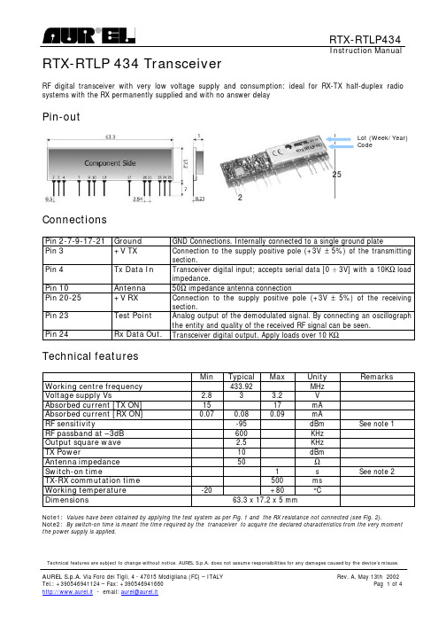
RTX-RTLP434Instruction ManualTechnical features are subject to change without notice. AUREL S.p.A. does not assume responsibilities for any damages caused by the device’s misuse.RTX-RTLP 434 TransceiverRF digital transceiver with very low voltage supply and consumption: ideal for RX-TX half-duplex radio systems with the RX permanently supplied and with no answer delayPin-outConnectionsPin 2-7-9-17-21 Ground GND Connections. Internally connected to a single ground platePin 3 +V TX Connection to the supply positive pole (+3V ± 5%) of the transmitting section.Pin 4 Tx Data In Transceiver digital input; accepts serial data [0 ÷ 3V] with a 10K Ω load impedance.Pin 10 Antenna 50Ω impedance antenna connectionPin 20-25 +V RX Connection to the supply positive pole (+3V ± 5%) of the receiving section.Pin 23 Test Point Analog output of the demodulated signal. By connecting an oscillograph the entity and quality of the received RF signal can be seen. Pin 24Rx Data Out.Transceiver digital output. Apply loads over 10 K ΩTechnical featuresMin Typical Max UnityRemarks Working centre frequency 433.92 MHzVoltage supply Vs2.8 33.2 V Absorbed current [TX ON] 15 17 mA Absorbed current [RX ON] 0.07 0.08 0.09 mARF sensitivity-95 dBm See note 1RF passband at –3dB 600 KHz Output square wave 2.5 KHz TX Power10 dBm Antenna impedance 50 ΩSwitch-on time1 s See note 2TX-RX commutation time 500 ms Working temperature -20+80 °CDimensions63.3 x 17.2 x 5 mmNote1: Values have been obtained by applying the test system as per Fig. 1 and the RX resistance not connected (see Fig. 2).Note2: By switch-on time is meant the time required by the transceiver to acquire the declared characteristics from the very moment the power supply is applied.225Lot (Week/Year) CodeRTX-RTLP434Instruction ManualThe declaired technical features have been verified by applying the following test system:Squelch threshold settingThe AUREL Transceiver mod. RTX-RTLP 434, normally presents, at the data output, 1 and 0 random commutations, corresponding to the noise generated by the transceiver itself.Such characteristic allows to make use of the maximum sensibility of the device. However, in certain application, where a low noise level is required, it is possible to connect a resistance of X value (see table) between transceiver T.P. pin and GND.The table here below shows for different resistance value, the obtained loss value:Model Loss (–1dB) Loss (-3dB) RTX-RTLP 434Rx = 10MRx = 5.6MFig. 2 Attenuation curve according to RX valueFig. 1RTX-RTLP434Instruction ManualBy accepting some commutation on the data output, it suffice to apply a resistance value that determines a 1 dB attenuation; attenuations of 3 dB increase the immunity to the noise till to obtain, to the data output, a logic, low and stable value in lack of RF signal.Device usageIn order to take advantage of the performances described in the technical specifications and to comply with the operating conditions which characterize the Certification, the transceiver has to be fitted on a printed circuit, considering what follows:3 V dc supply:1. The transceiver must be supplied by a very low voltage source, safety protected against short circuits.2. Maximum voltage variations allowed: ± 0,15 V.3. De-coupling, next to the transceiver, by means of a minimum 100.000 pF. ceramic capacitor.Ground:1. It must surround at the best the welded area of the transceiver. The circuit must be double layer, withthroughout vias to the ground planes, approximately each 15 mm.2. It must be properly dimensioned, specially in the antenna connection area, in case a radiating whipantenna is fitted in it (an area of approximately 50 mm radius is suggested.)50 Ohm line:1. It must be the shortest as possible.2. 1,8 mm wide for 1 mm thick FR4 printed circuits and 2,9 mm wide for 1,6 mm thick FR4 printed circuits.On the same side, it must be kept 2 mm away from the ground circuit. 3. On the opposite side a ground circuit area must be present.Fig.3 Suggested lay-out for the devicecorrect usageRTX-RTLP434 Instruction Manual Antenna connection:1. It may be utilized as the direct connection point for the radiating whip antenna.2. It can bear the connection of the central wire of a 50 Ω coaxial cable. Be sure that the braid is welded tothe ground in a close point.Antenna:1. A whip antenna, 16,5 mm long and approximately 1 mm dia, brass or copper wire made, must beconnected to the RF input of the transceiver.2. The antenna body must be keep straight as much as possible and it must be free from other circuits ormetal parts (5 cm minimum suggested distance.)3. It can be utilized either vertical or horizontal, provided the connection point between antenna andtransceiver input, is surrounded by a good ground plane.N.B:As an alternative to the a.m. antenna it is possible to utilize the whip model manufactured by Aurel (see related Data Sheet ed Application Notes).By fitting whip antennas too different from the described ones, the EC Certification is not assured.Other components:1. Keep the transceiver separate from all other components of the circuit (more than 5 mm).2. Keep particularly far away and shielded all possible microprocessors and their clock circuits.3. Do not fit components around the 50 Ohm line. At least keep them at 5 mm distance.4. If the Antenna Connection is directly used for a radiating whip antenna connection, keep at least a 5 cmradius free area. In case of coaxial cable connection then 5 mm radius will suffice.Reference RulesThe RTX-RTLP 434 transceiver is EC certified and in particular it complies with the European Rules EN 300 220-3 for class 2, and EN 300 683 for class 1. The equipment has been tested according to rule EN 60950 and it can be utilized inside a special insulated housing that assures the compliance with the above mentioned rule. The transceiver must be supplied by a very low voltage safety source protected against short circuits The use of the transceiver module is foreseen inside housings that assure the overcoming of the rule EN 61000-4-2 not directly applicable to the module itself. In particular, it is at the user’ s care the insulation of the external antenna connection, and of the antenna itself since the RF output of the transceiver is not built to directly bear the electrostatic charges foreseen by the a.m. rule.CEPT 70-03 RecommandationsIn order to comply with such rule, the device (strictly for what it concernes the tranbsmission phase) must be used only for a 10% of an hourly duty-cycle, (that means 6 minutes of utilisation over 60).The device usage inside the italian territory is governed by the Codice Postale and Telecomunicazioni rules in force (art. no. 334 and subsequents).The technical tests and reports have been carried out and obtained by the laboratories of :Messrs PRIMA RICERCA & SVILUPPO – via Campagna, 58 – 22020 Gaggino Faloppio (CO) - Italy I。
LN-23P 无线传输线缆馈器操作手册说明书

Operator’s ManualSave for future reference Date PurchasedCode: (ex: 10859)Serial: (ex: U1060512345)For use with machines having Code Numbers: 11671, 11384Register your machine:/registerAuthorized Service and Distributor Locator: /locator Need Help? Call 1.888.935.3877to talk to a Service RepresentativeHours of Operation:8:00 AM to 6:00 PM (ET) Mon. thru Fri.After hours?Use “Ask the Experts” at A Lincoln Service Representative will contact you no later than the following business day.For Service outside the USA:Email:*********************************SAFETYTECHNICAL SPECIFICATIONS – LN™-23PWIRE DRIVE ROLLS AND GUIDE TUBES The LN™-23P is shipped with the proper drive rolls and guide tubes factory installed. Do not adjust the idle roll tension adjusting screw. If the idle roll tension must be relieved temporarily, see “A” and “B” of Maintenance Section.OPTIONAL FEATURES INSTALLATION INNERSHIELD GUN AND CABLE•Unclip the rubber retaining strap that holds the wire enclosure cover in place and remove the cover.•Push the wire drive section door latch towards the rear of LN™-23P and open door.•Loosen the gun locking set screw in the conductor block on the front of the gear box with a 3/16 hex Allen wrench.•Lay the cable out straight. Insert the connector on the conductor cable thru the large grommet in the front of the wire drive section and into the brass block on the front of the gear box. Make sure it is all the way in and tighten the locking set screw witha 3/16 hex Allen wrench. Keep this connectionclean and bright.•Connect the 3 pin gun trigger connector to the lower receptacle.•If the gun cable being used has a reduced speed switch, connect the 4 pin reduced speed switch connector to the upper receptacle. If the reduced speed switch is not used, install the protective cap on the upper receptacle.K-350 ADAPTER KIT– Turn off power source and all power to power source.•SAM-400 Engine Welders: Attach the shock mounted mounting plate to the front of the SAM electrical component panel to left of the relay case with 4 of the #10 self-tapping screws provided.Older models require the drilling of 4 5/32 dia.holes into the panel. Connect the adapter control cable to the SAM terminal strips per the proper connection diagram.2. Remove compartment cover along with plastic wirereel brake and reel cover. Pull wire end from spool and route it through the liner opening that is mount-ed inside the wire reel case.3. Pull 2-3 ft. of wire through upper conduit cablepiece as shown in picture below.ELECTRIC SHOCK can kill.• Do not touch electrically hot parts. 5. Turn on power and trigger the gun to take up slackin the wire.6. Connect the upper conduit and lower Conduitpieces as shown in picture below.Reel Cover2-3 Feet Feed Wire thruLiner Opening.WARNINGWatch for kinks whenfeeding wire thru conduit.4. Add Reel Cover. Form a loop with the wire androute it through the lower conduit piece and pastthe drive rolls as shown below .Feed into DriveRolls in this area.LoopEnter Wire thru conduit pieceAdd Reel CoverINSTRUCTIONS FOR LOADING WIRE INTO LN™-23P(For machines that have code numbers Higher than 11384.)1. With the power shut off and input leads going to thewire feeder disconnected, lay LN™-23P down with wire reel facing up.DRIVE ROLL PRESSURE• Do not adjust the drive roll pressure. If the idle rolltension must be relieved temporarily, see (Maintenance Section).ADJUSTING WIRE FEED SPEED AND VOLTAGESet the wire feed as specified in the procedures using the calibrated dial on the back of the LN™-23P control box. When the reduced wire speed switch (mounted on the gun handle) is in Position No. 1, the wire feed speed will be that which is indicated on the dial. In Position No. 2, the wire feed speed will be 83% of the figure indicated on the dial.Set the voltage by adjusting the voltage control while welding until the voltage specified in the procedures is indicated on the meter. The meter reading with the power source on but not welding is the open circuit voltage. With some power sources, this voltage may be significantly higher than welding voltage.When establishing initial procedures, start with the voltage control set near minimum. Strike an arc on scrap steel. If the arc fails to start, increase the volt-age settings until the arc can be established.NEVER set the power source open circuit voltage higher than 50(1)volts. The LN™-23P will not feed wire when the voltage is higher than 50(1)volts.When using the CV Converter or the DC-600 and inching wire (not welding) at open circuit voltages below 20 volts or above 25 volts, feeding may be unsteady or the wire speed may vary from that set on the dial. This condition does not exist while welding.Minimum usable arc voltage is 14 volts.NOTE:For improved readability of the voltmeter in some applications, the voltmeter guard may be installed rotated end for end. This will result in the pro-tective bars crossing the meter face in a different loca-tion.MAKING THE WELDBe sure the proper contact tip for either .068" or 5/64"wire, as appropriate, is in the gun. The thread protec-tor should cover the external threads on the nozzle.Loosen the insulated screw on the side of the gun,rotate the gun nozzle to the position most convenient for the particular application, and retighten the insulat-ed screw.This Troubleshooting Guide is provided to help you locate and repair possible machine malfunctions.Simply follow the three-step procedure listed below.Step 1.LOCATE PROBLEM (SYMPTOM).Look under the column labeled “PROBLEM (SYMP-TOMS)”. This column describes possible symptoms that the machine may exhibit. Find the listing that best describes the symptom that the machine is exhibiting.Step 2.POSSIBLE CAUSE.The second column labeled “POSSIBLE CAUSE” lists theobvious external possibilities that may contribute to the machine symptom.Step 3.RECOMMENDED COURSE OF ACTIONThis column provides a course of action for the Possible Cause, generally it states to contact your local Lincoln Authorized Field Service Facility.If you do not understand or are unable to perform the Recommended Course of Action safely, contact your local Lincoln Authorized Field Service Facility.HOW TO USE TROUBLESHOOTING GUIDEService and Repair should only be performed by Lincoln Electric Factory Trained Personnel.Unauthorized repairs performed on this equipment may result in danger to the technician and machine operator and will invalidate your factory warranty. For your safety and to avoid Electrical Shock, please observe all safety notes and precautions detailed throughout this manual.__________________________________________________________________________L N ™-23P A D A P T E R K I T W I R I N G D I A G R A MM -C R M 33014H F G E C DF E D C B AF O R C O D E S B E L O W 10892E : T h i s d i a g r a m i s f o r r e f e r e n c e o n l y . I t m a y n o t b e a c c u r a t e f o r a l l m a c h i n e s c o v e r e d b y t h i s m a n u a l . T h e s p e c i f i c d i a g r a m f o r a p a r t i c u l a r c o d e i s p a s t e d i n s i d e a c h i n e o n o n e o f t h e e n c l o s u r e p a n e l s . I f t h e d i a g r a m i s i l l e g i b l e , w r i t e t o t h e S e r v i c e D e p a r t m e n t f o r a r e p l a c e m e n t . G i v e t h e e q u i p m e n t c o d e n u m b e r .C O N N E C T I O N O F C V C O N V E R T E R T O L N ™-23P ’S A ND S A -200 O R S A -250M -142656-22-84J4 1 -ME : T h i s d i a g r a m i s f o r r e f e r e n c e o n l y . I t m a y n o t b e a c c u r a t e f o r a l l m a c h i n e s c o v e r e d b y t h i s m a n u a l . T h e s p e c i f i c d i a g r a m f o r a p a r t i c u l a r c o d e i s p a s t e a c h i n e o n o n e o f t h e e n c l o s u r e p a n e l s . I f t h e d i a g r a m i s i l l e g i b l e , w r i t e t o t h e S e r v i c e D e p a r t m e n t f o r a r e p l a c e m e n t . G i v e t h e e q u i p m e n t c o d e n u m b e r .C O N N E C T I O N O F L N ™-23P A ND A D A P TE R K I T T O R 3S -250 O R R 3S -325M -112-E : T h i s d i a g r a m i s f o r r e f e r e n c e o n l y . I t m a y n o t b e a c c u r a t e f o r a l l m a c h i n e s c o v e r e d b y t h i s m a n u a l . T h e s p e c i f i c d i a g r a m f o r a p a r t i c u l a r c o d e i s p a s t e a c h i n e o n o n e o f t h e e n c l o s u r e p a n e l s . I f t h e d i a g r a m i s i l l e g i b l e , w r i t e t o t h e S e r v i c e D e p a r t m e n t f o r a r e p l a c e m e n t . G i v e t h e e q u i p m e n t c o d e n u m b e r .C O N N E C T I O N O F L N ™-23P A ND A D A P TE R K I T T O R 3S -400, 600 O R 800M -12-E : T h i s d i a g r a m i s f o r r e f e r e n c e o n l y . I t m a y n o t b e a c c u r a t e f o r a l l m a c h i n e s c o v e r e d b y t h i s m a n u a l . T h e s p e c i f i c d i a g r a m f o r a p a r t i c u l a r c o d e i s p a s t e d i n s i d e a c h i n e o n o n e o f t h e e n c l o s u r e p a n e l s . I f t h e d i a g r a m i s i l l e g i b l e , w r i t e t o t h e S e r v i c e D e p a r t m e n t f o r a r e p l a c e m e n t . G i v e t h e e q u i p m e n t c o d e n u m b e r .C O N N E C T I O N O F L N ™-23P A ND A D A P TE R K I T T O D C -250, D C -400 O R D C -600M -1427212-7-2001N O T E : T h i s d i a g r a m i s f o r r e f e r e n c e o n l y . I t m a y n o t b e a c c u r a t e f o r a l l m a c h i n e s c o v e r e d b y t h i s m a n u a l . T h e s p e c i f i c d i a g r a m f o r a p a r t i c u l a r c o d e i s p a s t e d i n s i d e t h e m a c h i n e o n o n e o f t h e e n c l o s u r e p a n e l s . I f t h e d i a g r a m i s i l l e g i b l e , w r i t e t o t h e S e r v i c e D e p a r t m e n t f o r a r e p l a c e m e n t . G i v e t h e e q u i p m e n t c o d e n u m b e r ..LN™-23P WIRING DIAGRAMS-171242-19-82MFIELD CALIBRATION OF K-316 LN™-23P P.C. BOARDS-169023-30-84MJapaneseChineseKoreanArabicREAD AND UNDERSTAND THE MANUFACTURER’S INSTRUCTION FOR THIS EQUIPMENT AND THE CONSUMABLES TO BE USED AND FOLLOW YOUR EMPLOYER’S SAFETY PRACTICES.SE RECOMIENDA LEER Y ENTENDER LAS INSTRUCCIONES DEL FABRICANTE PARA EL USO DE ESTE EQUIPO Y LOS CONSUMIBLES QUE VA A UTILIZAR, SIGA LAS MEDIDAS DE SEGURIDAD DE SU SUPERVISOR.LISEZ ET COMPRENEZ LES INSTRUCTIONS DU FABRICANT EN CE QUI REGARDE CET EQUIPMENT ET LES PRODUITS A ETRE EMPLOYES ET SUIVEZ LES PROCEDURES DE SECURITE DE VOTRE EMPLOYEUR.LESEN SIE UND BEFOLGEN SIE DIE BETRIEBSANLEITUNG DER ANLAGE UND DEN ELEKTRODENEINSATZ DES HER-STELLERS. DIE UNFALLVERHÜTUNGSVORSCHRIFTEN DES ARBEITGEBERS SIND EBENFALLS ZU BEACHTEN.JapaneseChineseKoreanArabicLEIA E COMPREENDA AS INSTRUÇÕES DO FABRICANTE PARA ESTE EQUIPAMENTO E AS PARTES DE USO, E SIGA AS PRÁTICAS DE SEGURANÇA DO EMPREGADOR.CUSTOMER ASSISTANCE POLICYThe business of The Lincoln Electric Company is manufacturing and selling high quality welding equipment, consumables, and cutting equipment. Our challenge is to meet the needs of our customers and to exceed their expectations. On occasion, purchasers may ask Lincoln Electric for advice or information about their use of our products. We respond to our customers based on the best information in our possession at that time. Lincoln Electric is not in a position to warrant or guarantee such advice, and assumes no liability, with respect to such information or advice. We expressly disclaim any warranty of any kind, including any warranty of fitness for any customer’s particular purpose, with respect to such information or advice. As a matter of practical consideration, we also cannot assume any respon-sibility for updating or correcting any such information or advice once it has been given, nor does the provision of information or advice create, expand or alter any warranty with respect to the sale of our products.Lincoln Electric is a responsive manufacturer, but the selectionand use of specific products sold by Lincoln Electric is solely within the control of, and remains the sole responsibility of the customer. Many variables beyond the control of Lincoln Electric affect the results obtained in applying these types of fabrication methods and service requirements.Subject to Change – This information is accurate to the best of our knowledge at the time of printing. Please refer to for any updated information.TABLE OF CONTENTS INSTALLATION OPERATION MAINTENANCE TROUBLESHOOTING DIAGRAMS。
- 1、下载文档前请自行甄别文档内容的完整性,平台不提供额外的编辑、内容补充、找答案等附加服务。
- 2、"仅部分预览"的文档,不可在线预览部分如存在完整性等问题,可反馈申请退款(可完整预览的文档不适用该条件!)。
- 3、如文档侵犯您的权益,请联系客服反馈,我们会尽快为您处理(人工客服工作时间:9:00-18:30)。
阿朗传输网管使用手册
V
HUA system office room 【HUA16H-TTMS2A-HUAS8Q8-HUAH1688】
阿朗传输网管使用手册
目录
1 网管登陆 (1)
2 当前告警查看 (2)
3 拓扑查看: (3)
4 光功率查询 (7)
5 历史告警查询 (9)
前言:鹰潭、吉安、景德镇PTN网络使用阿尔卡特传输设备,设备型号主要有1850TSS-320,1850TSS-160,1850TSS-5C和1850TSS-5R,后缀代表设备容量,比如:1850TSS-320代表设备最大支持320G的多速率交叉能力(相当于2048个155M)。
1850TSS-320和1850TSS-160主要用于汇聚层设备,1850TSS—5R主要用于接入层设备,带基站业务或宽带业务。
由于1850TSS-5C问题较多且容量不足,已逐渐升级成5R设备。
1 网管登陆
1.1 通过安全管控平台登陆吉安PTN本地网。
1.2 点击弹出的网页界面,可进入登陆界面,输入正确的用户名和密码。
2 当前告警查看
2.1 登陆成功后,选择左边菜单-》Operation-》Alarms,双击Gobal Alarms图标。
2.2 此时弹出告警浏览界面,监控主要关注MAJOR级别告警:Loss of Signal以及Hardware failure,点击左边树图中MAJOR栏,可选择查看MAJOR级别告警。
勾选掉菜单View-》Paginate sublist选项,可取消告警分页显示,提高告警查看效率。
若告警变成绿色表示告警已清除,若找不到此告警,表明告警已清除且被存入历时库,历史库中的告警需要登陆网元主页中查询,详见第5节。
由于告警查看界面无法关联到拓扑,要查看网络拓扑,需要启动Network Management服务,详见第3节。
3 拓扑查看:
3.1在登陆主界面中,选择左边菜单-》Operation-》Management,双击Network Management图标。
3.2 根据告警信息,查找告警网元:选择菜单Search-》Physical-》Nodes,可以显示所有网元,按Location(区县)排序,可以找到对应网元,注意区分5R和5C设备。
3.3 网元拓扑查看:右键点击找到的网元,选择Search-》Parent Map,可以跳转至网元拓扑。
3.4 在Maps子页中,选择Technology-》Physical,可查看网元拓扑连接。
网元颜色代表网元最高级别告警,红色为Critical告警,橙色为Major告警。
若网元太多,可在右边工具栏中输入网元名称进行模糊搜索定位(网元名称区分大小写)。
3.5 要查看上联的汇聚层设备,可右键点击网元:Search-》Physical-》Physical Connections(With End Points),此时可查看与网元相连的设备名以及端口名。
3.6查看该物理连接下所带的相关业务情况。
可执行如下步骤:
(1)选择Search->Physical->Tansport Link;
(2)进入Transport Link后,单击T-MPLS Section 进入下一步;
(3)在T-MPLS Section 层单击T-MPLS Tunnels,可看到所有的Tunnels业务情况。
并且在这一层可以查看到该物理连接使用的Tunnel。
4 光功率查询
4.1 右键点击网元,选择:Search-》Physical-》Equipment View,将弹出一个设备管理网页。
4.2系统默认进入Home界面,点击Alarms标签,可查看设备当前告警,在网页下方列出了各个级别的告警数量。
4.3据传输综合网管中的定位信息,如P2T10GE-1-1-4,点击左边树图中对应的光口,如XFP-1-1-4-1,在右边可显示Input Power,正常的光功率为-6~-16dBm,此处光功率为-40dBm,需检查尾纤或修复光缆。
5 历史告警查询
5.1 在设备主页中选择:Alarms-》Condition Log,在页面中填写告警开始时间和结束时间,Domain选项选择ALL,可查询出所有设备告警和光路告警。
5.2 在下方的Data Reported Alarms子项中,可看到LOS告警的发生和清除时间。