振动疲劳分析振动疲劳共43页
典型结构件的振动疲劳分析
ii
典型结构件的振动疲劳分析
图清单
图 1.1 基础激励振动疲劳试验装置 ........................................................................................ 4 图 1.2 铝合金疲劳裂纹扩展曲线及实物图.............................................................................. 4 图 1.3 复合膜材料疲劳寿命曲线............................................................................................ 5 图 1.4 有机塑料的 S-N 曲线 ................................................................................................... 5 图 1.5 LY12CZ 铝合金动态疲劳 S-N 曲线.........................................................................频率,模型修正,频率变化,裂纹扩展
i
典型结构件的振动疲劳分析
Abstract
At present, the conventional analytical methods of static fatigue has been formed a separate system, and in engineering applications are quite ripe. But in actual environment, the project structure is often working in the environment of the vibration loads, the principal loss of structure is caused by vibration. Only use the idea of static fatigue can not compeletly explain the vibration conditions of failure,because it omits the key role of the changes of frequency . As a result, we take the common typical structure of aircraft as analyzing objects. Futhermore, we use the finite element software of MSC.patran&nastran and fatigue as a platform building dynamic models to study its’dynamic features and fatigue life. This paper put forward a method which considers frequency as a main factor to predict the life of structure. All works of this paper includes: First, we choose unidirectional stiffened plate and linking slab which are widely used in aircraft as objects to complete the structural vibration fatigue experiments under resonant excitation, realizing band motivation of the incentive frequency tracking structure inherent frequency and studying structure life change rule and the dynamic change of natural frequency by the resonance conditions. Results show that structural dynamic characteristics have important influence on fatigue life and nature frequency with the fatigue process is drab degressive. Futhermore, all works Based on the MSC. Patran&nastran platform, establishing the typical structure finite element dynamic model to complete the modal analysis and validate the finite element model is correct. And we use the amended model to analysis structure dynamic response, so as to realize the fatigue life calculation. Moreover, considering frequency variation of structure damage effect, this paper puts forward the frequency as the main parameters of resonance fatigue longevity methods. Through reasonable simplification and assumptions, using the finite element software of ABAQUS to simulate the dynamic structure crack propagation (named frequency of dynamic decreasing process), dynamic analysis is studied on each stages. SN method and damage tolerance are picked to simulate the progress of Adopt SN method, damage tolerance is done by the way under the condition of simulation timely resonance fatigue life. The example shows that the method is simple and reasonable and provides reference for vibration fatigue analysis. Key words : vibration fatigue; typical structure; natural frequency; model modification; frequency change; crack propagation
热环境下飞行器壁板的振动疲劳分析

热环境下飞行器壁板的振动疲劳分析刘文光;严铖;郭隆清;贺红林【摘要】According to the vibration fatigue problem of hypersonic aircraft under the thermal-mechanical environment, impacts of the temperature change on vibration properties and fatigue life of aircraft panel are studied. Firstly, the temperature field and stress field are obtained by analyzing three dimension transient coupling thermal conduct and thermal stress. Then, impacts of the temperature and stress and theirs coupling on panel’ s vibration mode and fatigue life are discussed. During the analysis, the stiffness of panel material influenced by the temperature is considered. Initial stress additional stiffness matrix caused by thermal stress and initial displacement stiffness matrix caused by thermal strain are introduced. Results indicate that different modes the panel are going to be decreased because the performance is worsen by the action of temperature. Impactsof temperature grade on vibration mode are obvious. The vibration fatigue life is shortened because of the coupling effect.%针对高超声速飞行器热力环境引起的壁板振动疲劳问题,旨在研究温度变化对壁板结构振动特性及疲劳寿命的影响。
机载设备随机振动疲劳寿命分析-曹立帅

3σ的概率为0.27%。可以看出,随机变量超出3σ量级的可能性已很小,采用
3σ已可以满足工程要求。
由上可知,大于3σ的应力仅仅发生在0.27%的时间内,假定其不造成任何损
伤。在利用Miner线性累积损伤理论进行疲劳计算时,将应力处理成上述3个水平,
总体损伤的计算公式就可以写成:
D = n1σ + n2σ + n3σ
(4)
N1σ N2σ N3σ
n1σ :等于或低于1σ水平的实际循环数目(0.6831); n2σ :等于或低于2σ水平的实际循环数目(0.271); n3σ :等于或低于3σ水平的实际循环数(0.0433)。
N1σ , N2σ , N3σ 分别为根据疲劳曲线计算求得的1σ、2σ和3σ应力水平对 应的许可循环的次数。 2.3 随机振动疲劳寿命分析流程
次对材料的损伤为 D/N1,经 n1 次循环作用后,σ1 对材料的总损伤为 n1D/N1,如此
类推,当各级应力对材料的损伤综合达到临界值 D 时,材料发生破坏。用公式表
示为
n1D + n2D + n3D +... = D
(1)
N1 N2 N3
推广到更普遍的情况,即有
∑∞ ni = 1
(2)
N i=1 i
约束:试验台的底面设为固定约束; 载荷:在 X、Y、Z 三个方向上分别施加功率谱密度。
图 4 功率谱密度曲线
3.3 疲劳寿命评估 通过对计算结果的分析,得到控制壳体上危险部位出现在耳片位置上,同时
分别得到该部位三个方向上 1σ、2σ和 3σ应力。
图 5 X 方向加载时耳片危险部位最大 1σ应力图
材料抗拉强度σb =490MPa
7
N3σ=5.44×10 。
MSC_NASTRAN振动疲劳分析(Lec22_振动疲劳)
S22-15
模态叠加瞬态分析的优点
• 使得结构动力响应计算不需要存储每一节点/单元的 响应. • 考虑共振影响 • 这个方法类似于准静态方法,模态参与因子关联模 态应力 • 结合多体动力求解允许对整个装配体进行有效的瞬 态分析
PAT318, Section 22, September 2008 Copyright 2008 MSC.Software Corporation
● 模态(叠加)瞬态方法
● 系统的动力学特性和自由度被缩减到一组模态,因此求 解速度比直接法快.
● 需要选择一组合适的模态. ● 限于线性问题(一般采用这个)
PAT318, Section 22, September 2008 Copyright 2008 MSC.Software Corporation
frequency
Hale Waihona Puke 准静态分析➢ 确定静态有限元分析载荷和约束,以模拟工作环境 ➢ 测量或者预测载荷时间历程Pk( t ) ➢ 弹性应力历程是通过线性叠加方法进行计算:
ij,e (t)
k
Pk
(t
)
ij,e,k Pk,f ea
where k = loadcase ID.
PAT318, Section 22, September 2008 Copyright 2008 MSC.Software Corporation
S22-7
A
静态分析
● 优点:
● 有限元计算代价低. ● 硬盘空间要求少. ● 可以使同样的应力数据用于不同载荷事件的疲劳分析. (也就是多
事件) ● 自动排除可以用于在疲劳分析前选择实体以加速分析。
● 缺点:
● 静态有限元分析要求的某些约束可能不理想. ● 当系统固有频率接近外载频率时候精度不够.
电动汽车电池包随机振动疲劳及优化分析
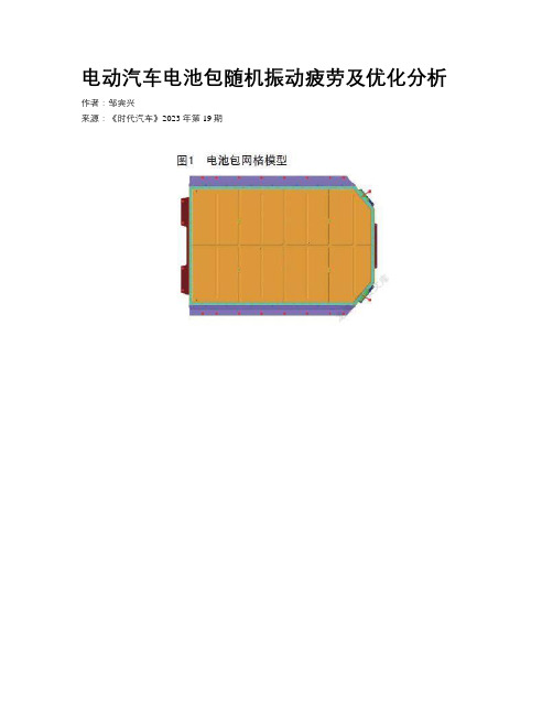
电动汽车电池包随机振动疲劳及优化分析作者:***来源:《时代汽车》2023年第19期摘要:电池包作为电动汽车重要的组成部件,路面传递的随机激励是电池包失效的重要原因。
本文根据有限元建模,单位载荷的应力响应求解及疲劳损伤的计算。
对电池包存在疲劳损伤值过大的情况,研究了通过提升电电池包模态频率以改善随机振动疲劳特性的优化思路。
最后再通过进行台架实验,验证了所分析思路和优化效果的有效性。
关键词:电池包随机振动疲劳功率谱密度近年来,汽车行业面临巨大变革,产业生产模式、竞争格局都在发生深刻变化,全球电动汽车销量再创新高,电动汽车将成为制造业核心竞争力提升中的重要一项。
由此可见,在市场及政策引导下电动车将替代燃油车成为主要的交通运输工具,其相关技术的开发也成为车企重点摸索的方向。
电池包系统作为不可缺少的核心部件,是车辆运行提供动力的心脏,其结构安全至关重要。
在车辆行驶过程过程中,受路面传递而来的外部振动载荷复杂,且随机性大。
因此,研究电池包在随机外部振动载荷下的结构特性,具有重要的工程意义[1]。
戴江梁等[2]基于随机振动理论与频域疲劳分析法,研究了电池包结构的失效机理。
王文伟等[3]基于三区间法计算了测试标准下电池包结构的振动疲劳特性。
孙小卯等[4]基于电池包动态特性,研究了电池包在振动过程中产生的疲劳问题。
本文将主要从电池包结构的随机振动疲劳方面进行分析研究。
1 电池包模型建立本文研究的电池包结构主要包括了电池包箱盖,电池模组,箱体及电池包底板等,为提升计算效率,建模之前,将电池包中包含的线缆、接口、继电器等对电池包结构性能影响不大模块省略。
本文采用Hypermesh软件进行建模,建模过程中将尺寸较小的结构如圆角、翻边进行适当简化[5]。
电池包整个箱体材料为AL6061,电池包箱盖和底板材料为Al5083,电池包整体重量545kg。
电池包本体结构通过抽中面及壳单元对电池包进行网格划分,单元平均尺寸取8mm。
2.5D_机织复合材料悬臂梁振动疲劳实验与有限元模拟
2023 年第 43 卷航 空 材 料 学 报2023,Vol. 43第 4 期第 111 – 121 页JOURNAL OF AERONAUTICAL MATERIALS No.4 pp.111 – 1212.5D机织复合材料悬臂梁振动疲劳实验与有限元模拟邓杨芳1, 王雅娜2,3*(1.中国航发四川燃气涡轮研究院,成都,610500;2.中国航发北京航空材料研究院 表面工程所,北京 100095;3.中国航发北京航空材料研究院 先进复合材料科技重点实验室,北京 100095)摘要:2.5D机织碳纤维增强树脂基复合材料以其在力学性能和复杂构件成型两方面的综合优势,在大涵道比商用涡扇发动机风扇叶片方面具有巨大的应用前景。
对发动机风扇叶片来说,振动疲劳是一种不可忽视的工况条件,目前2.5D机织复合材料振动疲劳方面的实验与数值预测模型十分有限。
本工作针对一种模拟发动机叶片根部的2.5D机织复合材料悬臂梁结构,建立一阶弯曲振动疲劳行为模拟的多尺度模型,并基于固定周期跳跃的疲劳加载模拟方法,结合主导疲劳失效机制的损伤萌生准则和疲劳刚度退化模型,开展2.5D机织复合材料经、纬向试件振动疲劳实验过程的模拟。
基于建立的多尺度模型分析试件危险部位单胞内的应力场,预测经、纬向试件振动疲劳实验后的损伤状态。
数值模拟结果与实验后的断口形貌观测结果吻合,验证了本工作提出的2.5D机织复合材料振动疲劳多尺度预测模型的有效性。
基于提出的振动疲劳多尺度预测模型,对随着疲劳加载次数累积经向试件工作段单胞内的损伤状态进行了仿真,揭示了2.5D机织复合材料振动疲劳损伤的演化机理。
关键词:复合材料;碳纤维;2.5D机织;多尺度;振动疲劳doi:10.11868/j.issn.1005-5053.2022.000208中图分类号:TB332 文献标识码:A 文章编号:1005-5053(2023)04-0111-11Vibration fatigue experiment and finite element simulation of 2.5D wovencomposite cantilever beamDENG Yangfang1, WANG Yana2,3*(1. AECC Sichuan Gas Turbine Establishment, Chengdu 610500, China;2. Surface Engineering Division, AECC Beijing Institute of Aeronautical Materials, Beijing 100095, China;3. Key Laboratory of Advanced Composites, AECC Beijing Institute of Aeronautical Materials, Beijing 100095, China)Abstract: 2.5D woven composite has great application prospect in high bypass ratio commercial turbofan engine fan blades due to its comprehensive advantages in mechanical properties and complex component forming. For the aero-engine fan blades, vibration fatigue is a working condition that can not be ignored. At present, the research on vibration fatigue behavior of 2.5D woven composite is limited, and there is a lack of numerical model for vibration fatigue behavior simulation. In this paper, a multi-scale model for the first-order flexural vibration fatigue behavior of a 2.5D woven composite cantilever beam simulating the root of engine blade was established. Adopting the fatigue loading simulation method which adopted the fixed cycle jumping strategy, and the damage initiation criterion and fatigue stiffness degradation model based on the leading fatigue failure mechanism, the vibration fatigue test processes of the wrap and weft specimens were simulated respectively. With the established multi-scale model, the stress field in the unit cell of the dangerous part of the specimen was analyzed, and the damage state of the specimen after the vibration fatigue test was predicted. The numerical simulation results are consistent with the observed fracture morphology after the test, which verifies the validity of the proposed multi-scale prediction model for vibration fatigue of 2.5D woven composite materials. In addition, based on the multi-scale prediction model of vibration fatigue proposed in this paper, the damage states in the unit cell atthe working section of the wrap specimen with the accumulation of fatigue loading cycles simulated, which is helpful to understand the evolutionary mechanism of vibration fatigue damage of 2.5D woven composite materials.Key words: composites;carbon fiber;2.5D woven;multi-scale;vibration fatigue三维机织复合材料是纺织结构复合材料的一个分支,是利用机织技术将纤维束织造成具有空间网状结构的预成型结构件,然后以预成型结构作为骨架进行浸胶固化而直接形成的复合材料结构。
电池组随机振动疲劳分析

电池组随机振动疲劳分析本例展示基于功率谱密度曲线(PSD)的电池组疲劳分析,即针对随机振动的疲劳寿命分析。
1 问题设定一块电池组,尺寸为70mm x 175mm x 400mm。
该电池组的两端共有6个端点,分别受到垂直于电池组平面的激励作用,且激励的加速度功率谱密度曲线(ASD)相同。
由于在随机振动基于线性动力学原理,因此电池,PC材料等采用实体建模,其他钣金采用壳单元建模,设定相关的fastener点焊单元,coupling耦合单元和tie约束,建立零件和零件之间相应的连接关系。
两端所对应的PSD谱线如下图。
请注意该曲线的频率截断在200Hz处。
本案例用到的附件包括:battery_SSD.cae 提取前10阶固有模态和扫频分析plate.psd PSD曲线2 分析过程一般来说,针对随机振动的疲劳分析包含两大步。
第一步是在Abaqus中完成固有模态和扫频两个计算;第二步是把这两个计算结果与PSD曲线一起输入fe-safe,运行若干设置后完成疲劳分析,得到相关结果。
2.1 有限元计算需要强调的是,在有限元计算部分,不采用随机振动分析方法,而是采用模态提取和扫频方法。
2.1.1 固有模态分析附件中的battery_SSD.cae第一个step分析步是用于提取固有模态的Abaqus计算文件。
其中的关键设置如下:a) 两端固定b) 提取1~200HZ内的固有模态c) 指定位移U和应力S作为场输出变量2.1.2 扫频分析第二个step分析步是用于扫频分析的Abaqus计算文件。
由于PSD曲线上的最高频率是200Hz,故而扫频分析的最大频率也截断在200Hz。
同时,设定各阶频率对应的阻尼均为2%。
定义单位加速度的base motion激励载荷,用于扫频分析:在输出设定上,对两个扫频分析Step,设定对广义位移GU和GPU的历程输出。
2.2 疲劳计算由前述的固有模态分析和扫频分析,计算得到结果文件:battery_shockZ_fastener.odb。
振动疲劳基础知识
振动疲劳基础入门:产品设计过程中的抗振性能优化及疲劳寿命评估振动疲劳基础知识振动基本概念振动是指物体沿一定路径往复运动的现象。
在机械系统中,振动是一种常见的运动形式,它可以是周期性的,也可以是非周期性的。
周期性振动包括正弦振动和余弦振动,而非周期性振动则表现为随机振动和瞬态振动。
振动的产生可以由各种各样的原因导致,如引擎的运转、地震、海浪等自然现象,或是人为因素如车辆行驶、建筑施工等。
振动的特征可以从频率、振幅、相位、波形等不同的方面进行描述。
疲劳失效疲劳失效是指结构在循环载荷作用下,逐渐产生微观结构的变化,导致结构在低于其承受静载强度的条件下发生破坏的现象。
疲劳失效通常发生在金属材料制成的结构中,是机械工程中一种常见的失效形式。
疲劳失效的原理主要是由于循环载荷作用下,材料内部的应力-应变循环会导致微观结构发生变化,如位错、滑移、微裂纹等。
这些微结构变化逐渐累积,最终导致材料出现宏观裂纹并发生破坏。
影响疲劳失效的因素包括材料本身的特性,如材料的强度、硬度、韧性等,同时也与循环载荷的大小、波形、频率等有关。
此外,环境因素如温度、湿度、介质等也会对疲劳失效产生影响。
振动疲劳实验振动疲劳实验是为了研究结构在振动载荷作用下的疲劳性能和疲劳失效机理而进行的实验。
实验的主要目的是确定结构的疲劳极限,了解结构的疲劳行为,以及探寻防止结构疲劳失效的措施。
振动疲劳实验通常采用振动台或激振器来对结构施加振动载荷。
实验过程中需要对结构的响应进行测量和记录,包括位移、速度、加速度、应力、应变等参数。
同时,还需要对结构进行无损检测,如超声检测、射线检测、磁粉检测等,以发现和评估结构的微观裂纹和宏观裂纹。
振动疲劳分析方法振动疲劳分析是根据实验数据和理论模型对结构的疲劳性能进行评估和预测的过程。
常用的振动疲劳分析方法包括:(1)理论分析法:根据材料的力学性能和结构的几何形状、尺寸等因素,建立疲劳分析的力学模型,推导出疲劳载荷谱和疲劳寿命计算公式。