TC-02A张力说明书.pdf
Interface Inc. 张力链载体力量传感器说明书

Operator Instructions for Tension LinksTable of ContentsIntroduction (3)Markings CE (3)Electromagnetic Compatibility (EMC) (3)Tension Link Type/Model Number (3)Supplier (3)Service (3)Installation and Operation (3)Unpacking (3)Checks Prior to Installation (3)Installation (4)Wiring and Electrical Checks (5)Tension Link Output (5)Checks after Installation (5)Calibration (5)Warnings/Hazards (5)Inspection and Repair (7)Repair (7)Inspection (7)Tension Link Specification (7)Cable Gland and Connector Configurations (7)Mating Connector Assemblies (9)Tension Link Output Options (9)Telemetry (9)Warranty (9)IntroductionThis instruction manual refers to the Interface Inc. range of tension links and includes instructions for both cabled and telemetry options. Before installing or operating any Interface tension link, this and any reference documents should be read and understood.These instructions must be retained and incorporated in the technical documentation for the machine or partly completed machinery into which the tension link is installed.Markings CEEach tension link will be marked with an individual serial number and CE label. The WLL (Working Load Limit) or SWL (Safe Working Load) will be shown as standard embossed on the link.Electromagnetic Compatibility (EMC)The electromagnetic compatibility of the load cell device can only be assessed in conjunction with the entire installation, including its control systems. The machine builder who installs this partly completed machinery into a machine is responsible for compliance with the EMC directive.Tension Link Type/Model Number∙WTSTL Wireless Tension Link Load Cell∙ITL Wired Tension Link Load CellSupplerInterface Inc. Tel: (480)948-5557401 East Butherus Drive Fax: (480)948-1924Scottsdale, AZ 85260 email: **************************Service(Repair, Support)Interface Inc. (address as above)Installation and OperationTo ensure safe and trouble free installation of the load cell measuring device, the tension link must be properly transported and stored, professionally installed and commissioned.UnpackingBefore removing the tension link, inspect the packaging for signs of damage and immediately inform the supplier if any damage is found. Unpack the tension link carefully, taking special care with cables and be aware to the possibility of damaging low range devices by mishandling. Ensure that calibration and instruction information is not inadvertently discarded.Checks Prior to Installation∙If the tension link is fitted with a cable and gland, check that the cable is held securely by the gland.∙If the tension link is fitted with a connector, check the connector is secure to the pin, check the plug and socket for any damage and check that the connector mates correctly.∙Check the cable for damage, such as cuts or abrasions, especially where the cable enters the gland or connector assembly.∙Check that all parts (as defined by the general arrangement drawing); cable assembly, anti-rotation bracket, split pins, nuts, washers, spacers, bobbins etc. are present.∙Check that all parts (as defined by the general arrangement drawing); cable assembly, anti-rotation bracket, split pins, nuts, washers, spacers, bobbins etc. are present.∙If the tension link is fitted with a telemetry module, check that the 2 off AAA batteries are correctly installed, that the two RED clips on the telemetry housing are closed and that the battery cover is secure.F IGURE 1InstallationTension links are normally classified as portable devices, and so the correct installation is critical to ensuring product life cycle. To avoid damage or loss of accuracy during installation, the following points should be followed.∙The direction of the load applied to a link should be linear as shown in figures 2 & 3.∙Ensure the link pin does not experience torque or bending forces during operation.∙The tension link should only be loaded in tension using the ØC holes as shown see figure 2 & 3. See figure 4 for two common examples of installations.∙For optimal performance a tight tolerance with the ØC loading holes is recommended.∙If the tension link is fitted with a telemetry unit then ensure that a clear line-of–sight between the transmitter and receiver is maintained and that objects or structures are kept at least one metre away from antennae wherever possible. The installer should also first read the Wireless Telemetry User Manual which can be found at thefollowing web address:https:///product-category/wireless-telemetry-system/F IGURE 2F IGURE 3Wiring and Electrical ChecksThe correct connection of the tension link to an instrument is critical to achieving and maintaining its performance and reliability:∙Wiring connections are given on the calibration certificate supplied with each tension link.∙Where a screened cable is fitted, that screen should be connected as indicated in the manual for the instrument the tension link is connected to.∙If a screened cable is fitted, the screen should be connected as specified by the manual of the instrument or signal conditioning board (including internally mounted boards) to which the tension link is connected to.∙Cable length should not be added or removed from the tension link, as this could alter the calibration figures.∙If a junction box is to be used, check the connections are of good quality, secure, clean and the enclosure is freeof moisture.∙Tension link cabling must be kept away from high power cables and equipment, high output RF equipment, inductive loads and generators. Cables must not be run alongside power cables.Tension Link OutputThe electrical output of the tension link should only be connected to instrumentation with a high enough input impedance, preferably 1Mohm or greater, in order to prevent loading effects on the output sensitivity of the tension link. Interface offers a wide range of digital and analog instruments ensuring compatibility.When setting up your tension link, the following points should be acknowledged:∙The zero load output given on the calibration certificate is the output of the tension link with no load applied. This includes the removal of the load caused by any lifting accessories.∙The load on an installed tension link will comprise of the load of your assembly (including sheaves blocks, shackles, ropes, hooks, slings etc.) and the active load (load lifted). Therefore, the output with no active load will be greater than the zero output indicated on the calibration certificate.∙The output from the tension link can be in various forms, 4-20mA, 0-10V, mV/V etc. See the calibration certificate for details.Checks after InstallationWith the tension link installed, check the displayed output is not negative, as this may indicate either a fault, or that a compressive force is being applied to the tension link. See Figures 2 and 3 for details of correct loading.When applying a load to the tension link the output should increase in the positive direction. Use the calibration certificate for reference, to compare the output observed at certain loads. If these are not the same, check the following:a) All electrical connections are correct, i.e. to an instrument or a junction box etc.b) If a connector is fitted, ensure that it is fully mated.CalibrationAll Interface tension links are calibrated in traceable test machines, configured to best simulate normal loading conditions. We endeavor to match the loading conditions that would be experienced in service, but it is not possible to totally simulate the on-site structure for every tension link manufactured. For this reason, and optimum system accuracy, calibration in the final assembly is recommended. On-site calibration should be performed in accordance with the manual for the instrument to which the tension link is connected to.Warnings/HazardsTension links are highly stressed devices, and commonly have safety factors between three and five times the rated capacity under static conditions. Fatigue applications and environmental factors can contribute to reducing this margin. The user should determine the effect of any substance to the exposed tension link materials. Where a corrosive environment is present, tension links can often be manufactured from corrosion resistant materials, or alternatively, isolation barriers can be employed between the corrosive environment and the tension link.The following points should be followed to avoid potentially hazardous situations:∙Do not weld near to installed tension links. Leakage currents may destroy the tension link circuits.∙Tension links are sealed units and must not be dismantled. Damaged tension links should be returned to Interfacefor any repairs and re-calibration.∙The accuracy of the system is dependent upon the correct installation of the tension link.∙Tension links must not be handled or carried by the cable.∙Tension links must not be subjected to shock loads, such as using a hammer to force an assembly together (fitting clevis pins into the mounting holes).∙The tension link must never be placed in a potentially explosive environment, unless the product is suitably certified (ATEX or IECEx).Inspection and RepairRepairOnly Interface personnel are authorised to carry out a repair or service to their products. All repairs or services will be carried out in the premises of Interface. The unit is not serviceable outside of Interface premises.InspectionAll Interface tension links should be subject to periodic inspection, which should include, but is not exclusive to the following checks:∙Completion of the checks after installation.∙Check output at zero load (shift in zero offset). Verify against calibration certificate.∙Inspect to see if the tension link has been damaged/worn or chemically attacked (from a corrosive environment or lubricants etc.).∙For cabled versions, verify the integrity of the cable.∙After any serious operating incident, repeat first four checks above.∙For tension links fitted with a telemetry module, check that the batteries are correctly installed. The battery holder shows pictorially the correct orientation.∙For tension links fitted with a telemetry module, check for any signs of water ingress to the battery compartment and for any battery corrosion.∙In the unlikely event of this device failing, fit new batteries (if applicable) and re-test. Only when this has been done should you report the fault. When reporting the fault, give a full description of the problem and the type of application the device is being used for.Tension Link SpecificationInterface tension links have datasheets which can be found at the following website address:https:///product-category/wireless-telemetry-system/Cable Gland and Connector ConfigurationsAll cable gland wiring colors or connector pin details are shown on the Calibration Certificate supplied.The removal or replacement of the cable gland or bulkhead connector or any adjustment or repair must either be performed by Interface or by a suitably qualified and approved engineer.Examples of cable gland and connector arrangements:F IGURE 4 F IGURE 5F IGURE 6F IGURE 7Mating Connector Assemblies∙Check both halves of the connector for any damage or obstructions.∙Align the connector assembly and mate the two halves, press firmly to ensure they are fully engaged.∙Tighten the locking sleeve, finger tight only to complete the mating process.∙Always fully disengage the locking sleeve before attempting to de-mate the connectorTension Link Output OptionsThe tension link can be fitted with a variety of built in (in-cell) signal conditioning pcbs, to offer either analog, voltage, current signals or RS485 digital signals (in various protocols). When a wireless signal is required, the tension link can be fitted with a WTS-BS-1 Telemetry Module.TelemetryThe WTS product range uses high performance two-way radio communication. Each tension link fitted with the telemetry module requires either a WTS-BS-1-HA handheld device, digital/analog interface or a base station and PC to communicate with.WarrantyAll Telemetry products from Interface Inc., ('Interface') are warranted against defective material and workmanship for a period of (1) one year from the date of dispatch. If the 'Interface' product you purchase appears to have a defect in material or workmanship or fails during normal use within the period, please contact your Distributor, who will assist you in resolving the problem. If it is necessary to return the product to 'Interface' please include a note stating name, company, address, phone number and a detailed description of the problem. Also, please indicate if it is a warranty repair. Thesender is responsible for shipping charges, freight insurance and proper packaging to prevent breakage in transit.'Interface' warranty does not apply to defects resulting from action of the buyer such as mishandling, improper interfacing, operation outside of design limits, improper repair or unauthorized modification. No other warranties are expressed or implied. 'Interface' specifically disclaims any implied warranties of merchantability or fitness for a specific purpose. The remedies outlined above are the buyer’s only remedies. 'Interface' will not be liable for direct, indirect, special, inciden tal or consequential damages whether based on the contract, tort or other legal theory. Any corrective maintenance requiredafter the warranty period should be performed by 'Interface' approved personnel only.。
张力纠偏控制器说明书TCEPC

用户手册User ManualTHIS INSTRUCTIONS1 TCEPC 张力纠偏控制器集手动张力控制和自动纠偏控制于一身。
手动张力控制部分采用工业级大容量开关电源构成,能精确调节0-24V /4A输出,控制磁粉离合器/制动器。
自动纠偏控制部分由大规模工业集成电路组成,抗干扰能力强,可靠性高,使用寿命长,能跟踪工作材料的边缘或对印刷线条进行高准确度的差动和摆动纠偏。
本系统广泛应用于塑料薄膜分切机、特种材料分切机、涂布机、印刷机、复合机等设备上。
系统性能参数:张力控制部分:输入电源: AC85V-264V 50/60Hz 输出: 0-4.00A DC24V超载及短路保护,并可外部0-10VDC信号控制。
实时显示输出电流纠偏控制部分:可手动/自动工作可工作于对边,对线方式单/双电眼输入响应速度可调带限位输入纠偏精度≤1mm233.1.张力控制旋动面板上按钮(如左图所示),即可调节输出电压从0-24之间线性变化。
控制器面板上方数码屏会实时显示输出电流值。
3.2.纠偏控制3.2.1运行前准备(一)外部接线,连接电源、电机电源线、限位开关线,按颜色和 编号对号接线。
(二)光电检测材料位置 对材料必须要注意,材料为反射光类(如薄膜、铝箔等),则衬底(如传动辊)应为吸光线漫反射材料(如橡胶辊、布料等)材料颜色差异越大越好,最宜于相色,材料边缘尽量移到中间位置,线条也应在二只光电头光斑中央位置。
(三)电机方向极性确定 按MAN/AUTO键 选择应处于手动状态,按方向左按键则电机运转,材料活动架往左移动,按方向右按键,则电机反将活动架右移动。
(四)限位开关控制马达停止方向确定 *投入电源开关ON *操作手动状态工作(MAN),按手动方向键,电机运转,然后在活动架移动向的限位开关,用螺丝刀之类的工具,碰上限位开关,电机运转停止,则表示限位有效,反之用螺丝刀碰上另一端限位开关,电机运转停止,则表示限位开关接线相反,必须给予调换。
SA-ZY-2×80Z 智能化液压张力机 使用说明书
甘肃诚信电力机具制造有限责任公司
图一 SA-ZY-2×80Z 张力机
图二 SA-ZY-2×80Z 张力机
目录
1. 概述..............................................................................................................................1 2. 性能参数......................................................................................................................3
2.1. 性能参数............................................................................................................ 3 2.2. 性能说明............................................................................................................ 4 2.3. 油位控制............................................................................................................ 5 2.4. 显示器使用说明................................................................................................ 6 3. 张力机操作............................................................................................................... 11 3.1. 主要控制元件说明.......................................................................................... 11 3.2. 张力机启动和停机.......................................................................................... 15 3.3. 张力机固定...................................................................................................... 16 3.4. 张力工况时的操作.......................................................................................... 17 3.5. 主动工况(牵引或送线)时的操作.............................................................. 19 3.6. 并轮牵引或放线.............................................................................................. 22 3.7. 牵引或送线、张力的操作.............................................................................. 23 3.8. 前支腿及夹紧油缸的使用.............................................................................. 23 3.9. 液压系统油温控制.......................................................................................... 24 3.10. 故障显示.......................................................................................................... 27 3.11. 张力机运输...................................................................................................... 27 4. 张力机保养............................................................................................................... 28 4.1. 柴油机保养...................................................................................................... 28 4.2. 机械传动部分的保养...................................................................................... 28
张力控制器说明书TC-608P

迴授式張力控制器盤面型TC-608P(內建LOAD CELL 放大檢出)(具通訊功能)使用操作說明書1.前言非常感謝您採用本公司開發TC-608P迴授式張力控制器(以下簡稱608P)。
在使用608P之前,為了充分地發揮608P的功能,以及確保使用者的安全,請先閱讀本說明書,以利方便日後的配線設計,參數設定及了解異常現象發生的原因與處理方法,請妥善保管本說明書。
當您使用中出現任何疑點本手冊無法提供您解決方案時,請您與本公司連絡,我們將竭誠為您服務,並請您繼續採用本公司的產品以及批評指教。
2.注意事項:.不可在送電中實施配線、或拆裝608P控制器的連接器。
.608P控制器的端子均為控制器的迴授信號與輸出信號接點,請勿作為他用。
.608P控制器的輸出端絕對不可連接至AC電源,及異電壓進入。
.請勿拆卸控制器外殼及做控制器零件的耐壓測試。
.電源是否為AC 220V ±10%輸入608P端子1,2接點。
3.TC-608P原理介紹本控制器是依據生產線上使用條件之設定捲取或放料以及物料生產所需的張力值,TC-608P會依設定以及LOAD CELL所傳回的感測值作比較計算後,修正輸出指令,以改變剎車力或捲取扭力的大小,自動達成實際張力和設定需求張力相同的高精度張力控制系統。
4.特點介紹:.高精度,高可靠性。
.張力值可以自行定義為:kg / N / LB。
.可直接接LOAD CELL輸入,數位化歸零與倍率調整功能設計,方便操作。
.數位化設計,特性不變。
.具人性化設計,易操作。
.具張力設定值、張力實際值輸出指令多功能顯示。
.具有主速加、減速增益延遲時間輸出功能。
.具參數停電記憶功能。
.具啟動增益功能,可補償啟動機械靜摩擦力。
.具停機張力打折功能,可克服停機張力過大問題。
.具RS-485通訊介面,可與PLC以及PC通訊。
.■ 標準規格外殼尺寸 : 96mm X 96 mm 開孔尺寸 : 92 mm X 92 mm電 源 電 壓AC 220 V + 10%硬 體 規 格1 組 LOAD CELL 輸入 0 ~ 4 mV 輸入, 浮動式歸零與放大2組AI (選配) DC 0~10V 輸入,12 bit 解析度,輸入阻抗200K 1組AO (1組選配) DC 0~10V 輸出,最大10mA ,12 bit 解析度 4組DI 乾接點或晶體方式(Low Active) 2組RELAY DO Relay A 接點 5A 250VAC/30VDCRS-485 MODBUS 通訊 (選配) 通訊採用RS-485介面 MODBUS RTU 協定,可由通訊啟動、修正、指定輸出、讀取等操作。
弹性吊索张力测试仪说明书
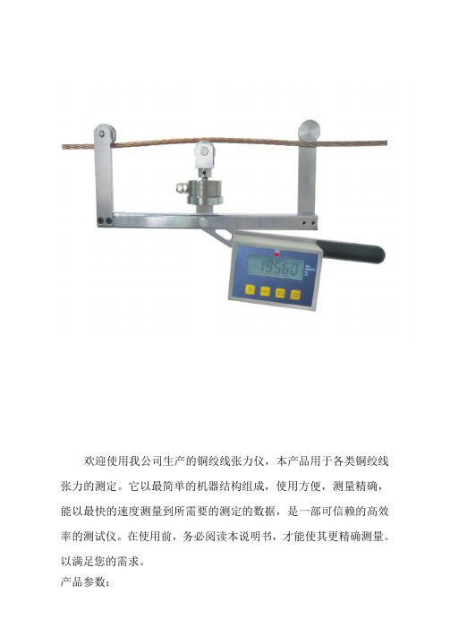
欢迎使用我公司生产的铜绞线张力仪,本产品用于各类铜绞线张力的测定。
它以最简单的机器结构组成,使用方便,测量精确,能以最快的速度测量到所需要的测定的数据,是一部可信赖的高效率的测试仪。
在使用前,务必阅读本说明书,才能使其更精确测量。
以满足您的需求。
产品参数:1、最大载荷:5000N2、测量铜绞线规格:7×2.5mmΦ7.5mm铜绞线。
3、测量精度:±2%4、重量2.3kg5、尺寸(长*宽*高)580*250*806、测量补偿0-10mm7、测量钢轮3个本型号专用于检验结构为7×2.5mm、计算外径为7.5mm的铜绞线一、产品原理:将铜绞线压弯至一定程度,使它垂直受力。
根据力的分解原理,可以利用垂直力得出铜绞线此时受到的张力。
因此,传感器上的力值经过仪表的运算,修正,放大后得出的就是铜绞线此时的张力。
如下图所示利用力分解原理当系统平衡时:T= 2F× cos(α/2)其中:T为推力;F为索拉力;α为索两侧的索夹角由于α固定相同,因此T与F成正比,让力T作用在力敏传感器上,力敏传感器输出信号,经电路运算、修正、放大后显示在显示屏上的数值就是所测索的张力。
放大倍数根据上面的公式计算,其中cos(α/2)=a/22ba 其中a为张力仪两侧滑轮平面至限位板间的距离,b为两测滑轮至推索轮距离的。
二、仪表显示面板:①峰值显示②实时值显示③单位显示④背光按键⑤单位按键⑥置零按键⑦峰值按键⑧开关按键显示窗口①为峰值显示,显示安装过程中的最大张紧力。
②为实时值显示,显示安装过程中的实时力。
③为单位显示,显示此时显示的力值单位。
按键功能1、开机:在关机状态下,按“开关按键”键,即可开机;2、关机:在测试状态下,按“开关按键”键,即可关机;3、置零:在测试状态下,按“置零按键”键,即可将测试值清零;4、峰值清除:在测试状态下,按“峰值按键”键,即可将峰值清除;5、切换单位:在测试状态下,按“单位按键”键,即可切换单位为“kgf”或“N”6、切换峰值模式:在测试状态下,长按“峰值按键”键,直到显示屏仅显示“PEAK”或“AUTO PEAK”即可,其中“PEAK”表示由按键清除峰值,“AUTO PEAK”表示峰值在保持10秒后,将会自动清除;7、切换背光模式:在测试状态下,按“索号按键”键,显示屏会显示“on”或“oFF”或“Auto”,其中“on“表示背光常亮,“oFF”表示背光常灭,“Auto”表示自动背光;三、标定操作:1、长按“置零按键”键,进入标定程序2、面板上显示“CAL=2”表示2点标定,按下方向键可以更换成“CAL=3”表示3点标定。
君达时代tc-a全自动附着力测试仪使用说明书

TC-A全自动附着力测试仪使用说明书深圳市时代之峰科技有限公司电话:135****0602网址:目录1.概述 (2)2.主要技术参数 (2)3.智能数值显示器功能 (3)3.1开机界面 (3)3.2数据查询 (3)3.3数据测量 (4)3.4参数设置 (4)4.仪器校准(申明:仪器出厂前均已经过标准测力计校准) (5)◆仪器校准请到具有计量检定资质的计量局等单位进行标定,用户请勿自行标定 (5)5.操作步骤。
(5)6.电脑连接 (7)7.注意事项 (7)8.产品标准配置 (8)附录A附着力检测记录表 (9)1.概述TC-A型自动拉拔式附着力测试仪可测量金属、混凝土及其他材质涂层的附着力。
该仪器的工作原理是利用液压系统使被测基体表面一定直径的涂层脱离来测量涂层的附着力,测试仪的多功能触摸液晶显示屏显示附着力的检测过程,以MPa或kN或Psi为单位显示。
该产品依据国际及中国相关标准设计制造,技术领先,性能稳定。
符合标准:①ISO4624《Paints and varnishes-Pull-offtest for adhesion》②ASTM D4541《StandardTest Method for Pull-Off Strength of Coatings Using Portable Adhesion Testers》③ASTM D7234《Standard Test Method for Pull-OffAdhesion Strength of Coatings on Concrete Using Portable Pull-Off Adhesion Testers》④GB/T5210-2006《色漆和清漆拉开法附着力试验》TB-T2965-2011《铁路混凝土桥面防水层技术条件》仪器特点:1、1280*720高清IPS触摸显示屏。
2、自动换算结果,锭子尺寸可选10mm/14mm/20mm/50mm(标配20mm锭子)。
张力控制器说明书
Haian Lanmeca Electromechanical Equipment Co., Ltd, which was founded in 1974; the main product families are magnetic powder clutch / brakes, tension controllers, torque testing system. In China it is one of the earliest corporation to R&D and industrialize these kind of products for mass production. Today hundreds of employees with around 30 engineers commit themselves to the company. Cooperating with famous universities, such as Fudan university, Tongji university, Tsinghua university and Beida university, aiming at worldwide advanced technology, the corporation develops more reliable、 durable and beautiful devices for customers. For magnetic powder clutch / brakes families, the corporation strictly complies with China Administration of Machinery Industry Standard: JB/T5988-1992 and JB/T5989-1992. It acquired ISO9001 c e r t i f i c a t i o n i n 2006 and EU certification in 2008. To ensure high quality products, the corporation set up one cast steel workshop to control material composition at the beginning of manufacturing process; largely use the digital-control lathes & CNC machining centers for process precision; at the end of process ,all the products will have functional test by torque testing system ( from 0.5 to 60000 N.m ) to guarantee high reliability. After year to year unremitting efforts, the corporation grows to land area of 30000 SQM & workshops 10000 SQM, fixed assets value of RMB 20 Million, and realized output 20000 units /sets in 2009. High quality and sound after sales service system bring more than 3000 worldwide customers to us. After collaborate with and delivery many excellent products to China Aerospace & Aviation Military Corporation, the company is authorized as a supplier to form a complete set for China Jiuquan Satellite Launch Center. Lanmeca, reliable partner! Lanmeca locates at new Haian city in the beautiful coast of Yellow Sea in East China. Welcome to Lanmeca! Sincerely looking forward to your valued suggestion and cooa a a a
TC—3A提升机安全性能检测仪使用说明书
目录目录-------------------------------------------------------1一. 概述--------------------------------------------------2二. 技术特性----------------------------------------------2三. 主要功能----------------------------------------------3四. 仪器面板布置 ----------------------------------------7五. 使用说明 -------------------------------------------- 8“0”. 参数输入 --------------------------------------9 “1”. 速度测试 --------------------------------------12 “2”. 制动测试 --------------------------------------15 “3”. 质量测试 --------------------------------------17 “4”. 时间测试 --------------------------------------19 “5”. 油压位移测试-----------------------------------22 “6”. 制动力测试 ------------------------------------25 “7”. 打印-------------------------------------------28六. 注意事项---------------------------------------------29七. 售后服务---------------------------------------------29 数据通信与测试分析----------------------------------------30 附:仪器附件装箱单1一、概述提升机是矿井生产的重要设备,保持提升机在良好状态下运行是安全和节能的重要环节。
全自动张力测定仪菜单及按键操作说明
全自动张力测定仪全自动张力测定仪菜单及按键操作说明仪器按键为无标识按键,在不同的显示界面下,按键具有不同的功能定义,由对应显示的菜单来决定,这样的设计减少了按键数量,按键功能定义明确,使人机界面更加友好。
在以下按键操作说明中,加黑反显的数字或图形为当前调整修改的内容。
1. 开机画面:液晶屏幕显示画面如下:图6-1连接好仪器电源线,打开电源开关,即进入开机显示画面。
在当前显示画面有五个功能项目可供选择:“参数设置”:进入参数详细设置画面“砝码标定”:进入仪器标定画面“纯水标定”:进入纯水标定画面“样品测定”:进入样品测试画面“历史纪录”:进入存储数据画面2. 参数设置画面全自动张力测定仪图6-2在当前显示画面下按“项目”键选择欲修改的参数,“跳格”键光标在当前参数的数值间横向移动,“增加”键对当前的参数数值进行调整,按“退出”键,保存参数并返回到开机画面如图6-1。
各参数的意义说明如下:重液密度――下层液体密度,单位:g/mL轻液密度――上层液体密度或气体密度单位:g/mL铂丝半径――铂丝环的半径单位:mm铂环半径――铂金环的平均半径单位:mm当前温度――环境温度单位:℃需要特别说明的是:1)当测试表面张力时,轻液密度输入的是空气的密度;当测试界面张力时,轻液密度输人的是上层液体的密度2)当前温度的数值指示的温度,可能与当前的实际温度有偏差,用户只需在这里输入当前的实际温度,仪器将自动计算之间的差值,作为修正因子保存,以后显示的温度值将按此差值进行修正。
3. 砝码标定界面使用砝码对仪器进行校准,画面如下:图6-3此项操作对仪器精度影响较大,需谨慎。
分两步执行:第一步:保证仪器调整到水平状态且铂金环洁净,等到仪器读数变化比较小,轻轻按下“归零”完成仪器归零操作。
全自动张力测定仪第二步:将满量程校准用的勾状砝码挂在铂金环横梁上,等到仪表读数变化比较小时,轻轻按下“校准”键,完成满量程校准操作。
“退出”键存储砝码校准结果,返回设置主画面如图6-1。
TC9000-LC2全自动张力控制器 说明书
()请务必在使用之前阅读5在打开控制器准备安装和接线之前要断开控制器电源至少要分钟。
正确的配置和安装是控制器正常运行的前提。
对以下几点要特别注意:●容许保护等级:保护接地,只有正确连接保护接地,才能减少外界电磁干扰。
●安装工作必须在无电状态下进行。
●与电网断开后,要等电容放电完毕,才可进行操作。
●不要让任何异物进入控制器内。
●在使用前,要除去所有覆盖物,以防止装置过热。
●切勿在易燃易爆等危险环境中使用。
●请勿将该产品安装在高温、潮湿等恶劣环境下。
●请勿将产品直接安装在易受震动冲击的环境中。
T C 9000系列张力控制器是一种高精度数字式可以自动控制卷材张力的自动控制仪器,它可以控制材料的放卷、送料、牵引及收卷张力。
第一章产品概述1.1概述D/A0.1%/●采用高精度转换器,输出精度可达,张力控制更精确。
●可以直接驱动磁粉(电磁)离合器制动器,也可控制变频、伺服等。
●可以接收单路或双路传感器输入信号,自动标定。
●金属外壳,坚固美观,更具有很强的防电磁干扰功能。
●插拔端子,接线安装方便。
自动调零,●可以双路输出控制。
人性化界面设计,操作十分方便。
●多行液晶显示,中英文菜单,编程简单,方便明了。
●内有密码功能,可以避免误操作改变设定参数。
●带有储存盒,可以将各种参数进行备份。
进行●1.2功能及特点磁粉制动器(放卷)1.编程键2.LCD递增键递减键11.自动控制模式下图为张力控制器面板TC9000-LC213.数值设定刻度盘[1]编程键:用这两个键可以进行各种菜单的选择或设定的确认。
返回键:按下此键可以返回到上一级菜单或返回到运行画面。
控制键确认键:进入编程菜单或确认设定参数。
手动控制模式键按下此键,控制器面板上手动指示灯()亮,控制器进入手动控制模式。
此时不受内部设定参数控制,按键键直接改变输出值。
自动控制模式键按下此键,控制器进入自动控制模式,此时面板上自动控制指示灯()亮,控制器处于自动运行状态,输出值受内部设定参数及、、控制。
- 1、下载文档前请自行甄别文档内容的完整性,平台不提供额外的编辑、内容补充、找答案等附加服务。
- 2、"仅部分预览"的文档,不可在线预览部分如存在完整性等问题,可反馈申请退款(可完整预览的文档不适用该条件!)。
- 3、如文档侵犯您的权益,请联系客服反馈,我们会尽快为您处理(人工客服工作时间:9:00-18:30)。
2.2 安装
TC-02A张力控制器可采用水平安装、立面安装或屏式开孔安装方式:
123
自动运行 设定值 10 .0Kg 实际值 10 .0Kg 输出值 50 .0%
168
4-M4*12
安装螺钉
256 水平安装
172.5 立面安装
2~4mm 140
屏式开孔安装
4-M4 244+-0.5
进入零张力标定界面。
小提示:如果传感器发生了零点飘移(即无张力时,测量张力不为0),则应进行零张力标定,此时可进入818菜 单 选 择 “ 零 张 力 标 定 ” 或 在 主 界 面 长 按[ E s c键] 3秒 , 快 速 进 入 零 张 力 标 定 界 面 。
2. 自动/手动切换键及指示灯 按此键可实现自动控制模式和手动控制模式的双向无扰切换。
数值设定旋钮
Set:确认键 Esc:取消键
▲+ :递增键/菜单向上键 ▼- :递减键/菜单向下键
OUTA:A轴输出指示灯 OUTB:B轴输出指示灯 ALM: 张力报警指示灯 COM: 通讯指示灯
1. Set/Esc 键: 用这两个键可以进行各种菜单的选择或设定的确认。 [Set键]: 进入下级菜单或确认执行。 [Esc键]: 返回上级菜单或确认返回。在主界面(即"手动控制"或"自动控制"画面),长按住3秒,可快速
TC-02A接收到上位机发送的有效命令,应答回送数据时COM灯点亮。
4
TENSION CONTROLLER TC-02A
第二章 安装与电气连接
2 实际值 10 .0Kg 输出值 50 .0%
154
60 147
228 245
单位:mm
60
16.5
140
2
TENSION CONTROLLER TC-02A
1.3 操作界面及操作简介
LED显示器 LED显示指示灯
LED显示切换键
123
自动运行 设定值 10.0Kg 实际值 10.0Kg 输出值 50.0%
电源指示灯 电源开关
LCD显示器 输出开关及指示灯 手动控制指示灯 自动控制指示灯 开门螺钉 键锁定键及指示灯 自动/手动控制切换键
在 手 动 模 式 下 , 手 动 指 示 灯 (M A N) 亮 , 此 时 可 以 旋 转 设 定 旋 钮 或 按[递 增/递 减 键]修 改 张
力设定 值 ,此时 如 果短按[自 动/手 动切换 按 键],则转 到 自动控 制 模式, 张 力设定 值 不变。 如果长 按[自动/手动 切 换键] 3秒, 则 转到自 动 控制模 式 ,同时 控 制器会 将 此时的 测 量值设 置为张 力 设定 值,实 现 勿扰切 换 。自动 模 式下 , 自动指 示 灯(AUTO)亮。
时 除[ LED显示 切换键]和[键锁 定键]外所 有 的按键 均 失效。 再 按一下 解 锁,见 锁定LED灯 熄灭。 6. OUTA : A轴输出指示灯
当A轴输出时,指示灯亮。 7. OUTB : B轴输出指示灯
当B轴输出时,指示灯亮。 8. ALM : 张力报警指示灯
当张力小于张力报警值[04]AL1时,ZT继电器动作,产生报警信号。 9. COM : 通讯指示灯
灯亮。 如果设 置 了锥度 系 数,长按 [LED显 示 切 换键] 3秒, 则复位 内 部锥度 。
小提示:如果设置了锥度系数,每次换新卷时必须先复位内部锥度。可以长按[LED显示切换键]来复位 ,或短接一下 外部端子的MCC与MC6。
3
TENSION CONTROLLER TC-02A
5. 键锁定键 为防止 误 操作的 发 生,控 制 器允许 对 按键进 行 锁定 。 按一下[键锁 定键]后,键 锁定LED灯 亮,此
器 感 传 力 张
TC-02A
器 动 制 粉 磁
全自动张力控制
1.2 功能特点
采 用32位 高速C PU,图 形 液晶 显 示,人 性 化设计 , 操作简 便 。 采 用无超 调P I算 法,张 力 控制快 速 稳定。 双工位切换,加减速补偿。 双2 4 V/4A输出 ,可直 接 驱动两 路 制动器/离 合 器。 可 输出0-1 0 V,4 - 2 0 m A驱 动变频 器/伺 服电机 。 安装调试简单,张力标定过程简单。 支 持标准M odbus通讯 协 议,所 有 参数开 放,连 接P LC/触摸 屏非常 方 便。 参数密码保护,防止误操作。 张力测量高稳定,无温飘。
此时系统处于停机状态,不进行自动PID调节。
3. 输出开关键及指示灯 此键控制输出开关,重复按此键,输出则在ON/OFF之间切换。 允许输出时,OUTPUT ON/OFF指示灯亮; 禁止输出时,OUTPUT ON/OFF指示灯灭,LED显示器显示0FF,输出值为0.0%。
4. LED 显示切换键及指示灯 按此键 可 使LE D显 示器分 别 显示测 量张力K gf(公 斤), 测 量张力N (牛顿), 输 出功率%。 对 应指示
第三章 菜单操作 .......................................... 8 3.1 画面与菜单结构 ..................................... 8 3.2 主要画面介绍 ....................................... 9 3.3 参数说明 .......................................... 10
第二章 安装与电气连接 .................................... 4 2.1 外形尺寸 ........................................... 5 2.2 安装 ............................................... 5 2.3 电气连接 ........................................... 6
第四章 自动张力控制 ...................................... 11 4.1 张力测量 ........................................... 11 4.1.1 张力传感器安装及接线 ........................... 11 4.1.2 张力测量相关参数设置 ........................... 12 4.1.3 张力标定 ....................................... 13 4.2 调试运行 ......................................... 15 4.2.1 手动控制 ....................................... 15 4.2.2 自动控制 ....................................... 15 4.2.3 比例积分参数设置 ............................... 16 4.2.4 系统启停 ....................................... 17 4.2.5 双轴切换 ....................................... 18 4.2.6 加速/减速控制 .................................. 20 4.2.7 报警功能 ....................................... 21 4.2.8 反馈方式 ....................................... 21 4.2.9 第二输出 ....................................... 21 4.3 锥度张力控制 ....................................... 22 4.3.1 锥度控制概述 ................................... 22 4.3.2 锥度张力模式运行画面 ........................... 22 4.3.3 锥度张力控制调试步骤 ........................... 22
第六章 故障排除及维护 .................................... 24 第七章 附录 .............................................. 25
7.1 参数画面 ........................................... 25 7.2 张力传感器工件原理.................................. 26 7.3 尺寸图 ............................................. 27 7.4 装配图 ............................................. 27 7.5 张力传感器安装 ..................................... 27 7.6 技术规格 ........................................... 28
张力控制装置系列
Tension Control System
全自动张力控制器(微偏位式)
Full Automatic Tension Controller
使用说明书
INSTRUCTION MANUAL
TC-02A
TENSION CONTROLLER TC-02A
目录
第一章 产品概述 .......................................... 1 1.1 概述 ............................................... 2 1.2 功能特点 ........................................... 2 1.3 型号定义 ........................................... 3 1.4 操作界面及操作简介 ................................. 3