OMP 马达样本
三洋伺服电机P系列样本

3.5
4.5
2,000
1,500
2,000 16.7
2,000 21.6
21.6
32.4
45.6
69.6
17.5
18.4
22.1
23.2
45.5
52.7
1.23
符号
PR NR Nmax TR TS TP IR IS IP KT KEф Rф QR te tm JM JM
32.6 32.4
0.37 (1.4)
-4
3.4X 10 5.0
44.7
WE
TB
VB
IB
JB W
150A
5.8
7.5
6.8
P10B13150BXS 《 130 》 1.5
7.4 8.8 19.6 6.9 7.9 17.9 1.34 47.0 0.84 15.0 5.3 4.9 35.08X 10⁻⁴ 35.1X 10⁻⁴
20 to 90%(无结露)
适用的驱动器型号
V10
驱动器电源
Munsell N1.5 or equ驱i动器v使a用l温e度n,t湿度,温度
(circumference)
电源容量
永久磁铁
驱动器重量
法兰安装
N ote 1. 为标准驱动器,温度达到饱和状态时的值
2. 为绕组温度为20OC的值
12 7.5 6.3 73.08X 10⁻⁴ 73.1X 10⁻⁴
23.1
90(24)
温度:0-4oC0 湿度:90%以下(应无结露)
50A
100A
200 to 230V AC+10%-15% 50/60Hz+-3Hz 3-phase 0-5oC5 湿度:90%以下(无结露)
M+S摆线马达样本(全)

MISSIONM+S Hydraulic persuids one goal only – customer satisfaction with highest quality,lowest possible prices and the best service. Everyone of the company’s staff is motivated to manufacture quality products in meeting the requirements you need andexpect. M+S Hydraulic has the know-how how to develop solutions for productivityand efficiency in nearly every country in the world.HYSTORYM+S Hydraulic was established as a state company in 1963, servicing the constructionindustry – excavating machines, bulldozers and autocranes. An year later the companystarted producing press for cable shoes. In 1966 it started manufacturing loaders andhydraulic systems for housing construction.A critical point is 1972 – the company is specialized in the hydraulic equipment only.In December 1976 it began manufacturing hydrostatic steering units for applicationon low speed vehicles, fork lifts, tractors and harvesters 60 km/h maximum. 1981 isthe initial point for production of low speed, high torque planetary hydromotors, new type of hydrostatic steering units and valve blocks.Now, M+S Hydraulic is one of the major producers of low speed, high torquehydraulic motors in the world. The motors are available in displacements of 8 to 630cu.cm, peak pressure up to 300 bar, maximum speed to 2450 rpm, variety ofmounting flanges and shaft ends. As well as the company manufactures completerange of hydrostatic steerings for low speed vehicles with maximum speed of 60 km/h,open and closed center, load and non-load reaction and accessories.M+S Hydraulic products quality is officially recognized with ISO9001 certificate and is guarranteed by very experienced, long-term employees.APPLICATIONM+S Hydraulic products are used in various of machines and systems in the fields of Agriculture, Industrial, Mining and Mobile industries. The motors are applicable to feeding mechanism of robots, manipulators, metal working machines as well as to driving various of units in agricultural machines, fans, extrusion machines in engineering and food industries, conveyors and so on, where an infinitely-variable speed regulation and mounting flexibility are required. Some of the motors could be mounted directly to the vehicle wheels.Steering units with radial fluid distribution are applicable to vehicles where an energy saving is required. The maximum vehicle speed should not exceed 60 km/h.WARRANTYM+S Hydraulic warrants,what it's products are free of defects in material or workmanship.This warranty will apply only to defects appearing within2years after the date of production of the product.If Customer notify M+S Hydraulic within the above period about any such defects,M+S,at its sole option will replace or repair the defective products.THE FOREGOING LIMITED WARRANTY IS AVAILABLE ONLY IF“M+S HYDRAULIC”IS PROMPTLY NOTIFIED IN WRITING OF THE ALLEGED DEFECT AND DOES NOT COVER FAILURE TO FUNCTION CAUSED BY DAMAGE TO THE PRODUCT,IMPROPER INSTALLATION,UNREASONABLE USE OR ABUSE OF THE PRODUCT,FAILURE TO PROVIDE OR USE OF IMPROPER MAINTENANCE OR USUAL,DEGRADATION OF THE PRODUCT DUE TO PHYSICAL ENVIRONMENTS OF AN USUAL NATURE.THE FOREGOING REMEDIES ARE THE SOLE AND EXCLUSIVE REMEDIES AVAILABLE TO CUSTOMER.LIMITATION OF LIABILITY M+S Hydraulic's liability for any claim of any kind, for any loss or damage arising out of,connected with or resulting from an order,or from the performance or branch thereof,or from the design,manufacture,sale delivery,operation or use of any of its products shall be limited to,at M+S's sole option,replacement,repair of any defective product or the issuance of a credit to Customer against any future purchases.Cash refunds will not be made under any circumstances and Customer will not be entitled to recover any damages of any kind against M+S Hydraulic,including but not limited to incidental or consequential damages,whether direct or indirect,known or unknown,foreseen or unforeseen.MOTORSHYDRAULIC Specification data Function diagrams Dimensions and Shaft extensions Permissible shaft Motor with Order code .......................Speed CONTENTSDisplacement,Max.Speed,GENERAL*Intermittent operation:the permissible values may occur for max.10%of every minute.**Peak load:the permissible values may occur for max.1%of every minute.***For speeds of 30RPM or lower,consult factory or your regional manager.1.Intermittent speed and intermittent pressure drop must not occur simultaneously.2.Recommended filtration is per ISO cleanliness code 20/16.A nominal filtration of 25micron or better.3.Recommend using a premium quality,anti-wear type mineral based hydraulic oil4.Recommended minimum oil viscosity 13mm²/s at operating temperature 50C.5.Recommended maximum system operating temperature is 82ºC.6.To assure optimum motor life fill with fluid prior to loading and run at moderate load and speed for 15-30min.HLP(DIN51524)or HM (ISO 6743/4).If using synthetic fluids consult the factory for alternative seal materials.EPMM 8EPMM 12,5The function diagrams data was collected at back pressure 5÷10barand oil with viscosity of 32mm²/s at 50°C.EPMM 20EPMM 32The function diagrams data was collected at back pressure 5÷10bar and oil with viscosity of 32mm²/s at 50°C.EPMM40EPMM50The function diagrams data was collected at back pressure5÷10barHYDRAULIC MOTORS EPRMDisplacement,Max.Speed,Max.Torque,Max.Output,Max.Pressure Drop,Max.Oil Flow,Min.Speed,Pressure fluid Temperature range,Optimal Viscosity range,Filtration[cm /rev.][RPM][daNm][kW][bar][l/min][RPM][C][mm /s]3O251,5÷397150÷7755÷1370÷17540÷6010Mineral based-HLP(DIN 51524)or HM(ISO 6743/4)10,1÷61-30÷9020÷75ISO code 20/16(Min.recommended fluid filtration of 25micron)GENERALOil flow in drain lineSpecification data ...............32÷35Function diagrams ..............36÷40Permissible shaft Seal Pressure ...40Dimensions and mounting ........41Wheel motor ............................42Shaft versions ...........................27Permissible shaft loads ..............28Motor with Order code (43)Speed Sensor............29CONTENTSOPTIONS»»»»»»»»»Model-Spool valve,roll-gerotor Flange and wheel mount Motor with needle bearing Side and rear portsShafts-straight,splined and tapered Shaft seal for high and low pressure Metric and BSPP ports Speed sensoring Other special featuresAPPLICATION»»»»»»»ConveyorsFeeding mechanism of robots and manipulators Metal working machines Textile machinesMachines for agriculture Food industriesetc.Grass cutting machineryCONTENTS Specification data Function diagrams Dimensions andShaft extensions Permissible shaftOrder code.........................GENERAL Displacement,Max.Speed,Max.Torque,Max.Output,*Intermittent operation:the permissible values may occur for max.10%of every minute.**Peak load:the permissible values may occur for max.1%of every minute.***For speeds of 10RPM or lower,consult factory or your regional manager.1.Intermittent speed and intermittent pressure drop must not occur simult neously.2.Recommended filtration is per ISO cleanliness code 20/16.A nominal filtration of 25micron or better.3.Recommended using a premium quality,anti-wear type mineral based hydraulic oil4.Recommended minimum oil viscosity 13mm²/s at operating temperatures.5.Recommended maximum system operating temperature is 82C.6.To assure optimum motor life fill with fluid prior to loading and run at moderate load and speed for 10-15minutes.a HLP(DIN51524)or HM (ISO 6743/4).If using synthetic fluids consult the factory for alternative seal materials.0DIMENSIONS AND MOUNTING DATAPP :T :(A,B)2xG1/2or 2xM22x1,5-15mm depthG1/4or M14x1,5-12mm depth (plugged)Standard Rotation A CW B CCWViewed from Shaft End Port Pressurized -Port Pressurized -Reverse RotationA CCW Viewed from Shaft End Port Pressurized -Port Pressurized -B CWCB -ø32straight,key A10x8x40DIN 6885Parallel SA -splined B25x22DIN 5482Max.Torque 40daNmKB -tapered 1:10,Woodruff key 6x9DIN6888C -ø25straight,Parallel key A8x7x30DIN 6885Max.Torque 34daNmCO -ø1"straight,key ¼"x¼"x1¼"BS46Parallel SH -splined,BS 2059(SAE 6B)HB -øsplined ,DP12/24ANSI B92.1-1976Max.Torque 95daNm1¼"14T Permissible Shaft Loads EPMLC CO CB KB----ø25straight,Parallel key A8x7x30DIN6885ø1"straight,Parallel key ¼"x¼"x1¼"BS46-ø25,3splined BS 2059(SAE 6B)-ø24splined B 25x22DIN 5482ø32straight,Parallel key A10x8x40DIN6885-ø1¼"splined 14T ANSI B92.1-1976ø35tapered 1:10,Woodruff key 6x9DIN6888SH SA HBORDER CODEMounting Flange- Displacement code*- Shaft extensions**omit -Square mount -Oval mount ,four holes,four holes F5080100125160200250315400-49,5[cm /rev]-79,2[cm /rev]-99,0[cm /rev]-123,8[cm /rev]-158,4[cm /rev]-198,0[cm /rev]-247,5[cm /rev]-316,8[cm /rev]-396,0[cm /rev]333333333NOTES:*S **The permissible output torque for shafts must be not exceeded!***C eeFunction diagrams from page 19 to page 23.olor at customer's request.The hydraulic motors are mangano-phosphatized as standard.BSPP (ISO 228)Metric (ISO 262)- Rotation(Paint)***Option -Design Series PortsStandard Rotation -Reverse Rotation -no Paint Painted -Corrosion Protected Paint omit -Factory specified-none -Low LeakageLow Speed Valve Free Running Special Features (see Specification data-page 45)*Intermittent operation:the permissible values may occur for max.10%of every minute.**Peak load:the permissible values may occur for max.1%of every minute.***For speeds of 10RPM or lower,consult factory or your regional manager.1.Intermittent speed and intermittent pressure drop must not occur simult neously.2.Recommended filtration is per ISO cleanliness code 20/16.A nominal filtration of 25micron or better.3.Recommended using a premium quality,anti-wear type mineral based hydraulic oil4.Recommended minimum oil viscosity 13mm²/s at operating temperatures.5.Recommended maximum system operating temperature is 82C.6.To assure optimum motor life fill with fluid prior to loading and run at moderate load for10-15minutes.a HLP(DIN51524)or HM (ISO 6743/4).If using synthetic fluids consult the factory for alternative seal materials.0。
伊顿摆线马达2K_(样本)
70
105
D 压力 Bar 140 170 205
240
275
310
0.95
85 3 110 37 110 81 115 170 115 259 115 349 115 439 115 530 110 622 110 714 110 795 105 880
1.90
145 34 150 78 150 166 150 254 150 341 155 429 155 516 150 603 150 689 150 775 145 861 175 28 180 72 185 159 185 246 190 333 190 420 195 507 195 593 190 679 190 765 185 851 205 22 210 65 215 152 225 238 230 325 230 411 235 497 235 584 230 670 230 756 225 842 220 14 235 57 250 140 255 223 265 306 270 388 270 470 270 553 270 635 265 717 260 799 240 2 265 49 280 128 290 207 300 286 305 364 305 442 305 521 305 599 300 677 295 755
55 7 65 21 70 45 70 92 75 140 75 187 70 235 70 283 65 331 65 378 60 426 60 474 55 522 50 569 50 593 35 713
110 5 130 19 135 42 140 89 145 137 150 184 150 231 150 279 145 326 145 374 140 422 135 469 130 517 130 564 130 587 120 706
液压马达产品样本OMR-SAUER DANFOSS

突发网络流量分析与排查方法研究网络世界已经成为我们日常生活中不可或缺的一部分,如今人们几乎离不开互联网,网站和应用程序。
因此,对网络安全的关注也越来越高。
当有突发情况发生时,网络管理员需要对突发的网络流量进行分析和排查,以确保网络稳定和安全。
本文将探讨突发网络流量分析的方法和技巧。
一、为什么需要网络流量分析与排查?网络管理员需要定期监视网络流量,以确保网络的安全和稳定性。
常见情况包括拒绝服务(DDoS)攻击、间谍软件攻击和网络钓鱼攻击等。
当出现突发情况时,例如恶意代码感染网络,会大量增加网络上的流量,导致网络变慢或完全瘫痪。
此时,网络管理员需要尽快确定问题的原因并采取措施,以防止网络继续受到攻击。
二、网络流量分析工具网络流量分析工具通常指网络协议分析器。
这些工具可以分析网络流量并确定恶意流量的来源。
目前市场上有很多流量分析工具,其中一些是商业软件,另一些则是免费开源软件。
以下是常见的几种工具:1. WiresharkWireshark是一款流行的开源网络协议分析器。
它可以抓取网络流量并在图形化界面中以人类可读的方式显示数据包的详细信息。
Wireshark支持上千种网络协议和过滤器,提供多种颜色编码和筛选工具,可提供有关网络流量的详细信息。
2. tcpdumptcpdump是一种流行的命令行流量分析工具,可在Linux和类Unix操作系统上使用。
它侧重于抓包和流量过滤,并且能够输出结果文件以进行后续分析。
3. NetFlowNetFlow是一种流量分析技术,可捕获网络流量数据并生成报告。
它是一种流程完整的网络流量分析工具,可提供实时分析和历史视图。
三、网络流量分析的过程1. 抓取网络流量要分析流量,首先需要使用抓包工具捕获网络流量。
抓包工具可以是Wireshark、tcpdump或其他软件。
此外,网络管理员还可以通过存储日志数据、利用IDS/IPS系统和抓取网络数据包等方式进行流量捕获。
2. 过滤数据包一旦捕获了网络流量,需要对数据包进行过滤。
力士乐A6VM变量马达6系列样本资料及特性

!"a !"b
A1 28 55 80 107 140 160 200 !DA 250
A2
A3
A4
A5
A6
X1 X2 GE-8LM GE-8LM GE-8LM GE-8LM GE-8LM GE-8LM GE-8LM
max max
0.8 Vg 0.8 Vg
max max
FKM
!" !DIN 5480 !"DIN 6885
4
ISO ISO
! 4 8 !"# SAE !"#$% SAE !"# ! !"#$ ! !" #
A/B A/B
A/B
SAE !"# $%+ !"#$%& 2) !"#$
!"#$! !"#$%&'(250 !" !"#$%& '() !"#$%&' !"#$% !"#$% &'( !"#$%& !"#$%& !"# Vg min !" #$HA !" #$HD, HZ, EP, EZ, DA Vg max
DA2, DA3, DA5, DA6 !"#$%&'"(&) V g max !"#$%&'()"#* !"#+, !"# !"#$%&'()a !"#b !"#$%&'()*+,-#. !"#$%V g max !"a, b 12V 1.6A(min) 0.8A(min) *+,-.+
OMP系列主要性能参数精

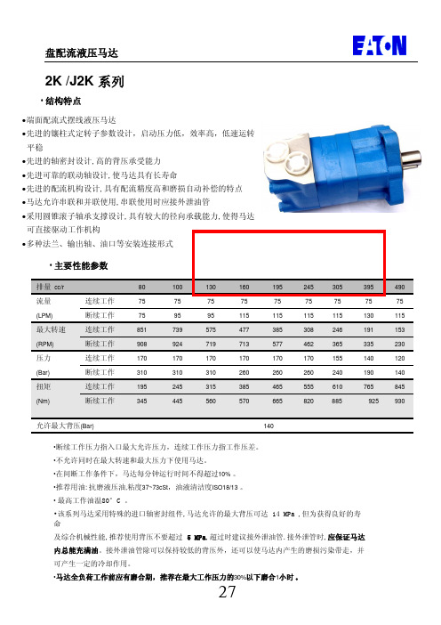
OMP系列主要性能参数排量 cc/r 50 63 80 100 125 160 200 250 320 400 500流量连续38 45 57 57 57 57 57 57 57 57 57LPM 间断45 53 68 68 68 68 68 68 68 68 68转速连续698 663 684 580 452 353 284 235 178 145 110RPM 间断859 774 824 659 544 364 339 281 210 180 136压力连续124 124 124 124 124 115 110 100 90 90 83Bar 间断138 138 138 138 138 124 124 124 124 110 90扭矩连续78 99 126 158 194 234 280 318 366 457 527Nm 间断86 110 140 176 216 256 365 394 504 558 570参考重量kg 5.1 5.4 5.6 6.2 6.5 6.7 6.9 7.4 7.7 7.8 8.2允许侧向负荷(额定转速下)◎间断工作压力指入口最大允许压力,连续工作压力指工作压差。
◎不应同时在最大转速和最大压力下使用马达。
◎间断压力或间断转速允许持续时间为:每分钟最多10%的许可值。
◎推荐用油:抗磨液压油,粘度37-73cst,油液清洁度ISO18/13 。
◎最咼工作油温80 °C。
◎特殊的动密封设计,马达允许的最大背压可达10MPa ,但为获得良好的寿命及综合性能,推荐使用背压不要超过5MPa ,超过时建议接外泄油管,接外泄管时,应保证马达内总能充满油。
外泄管路应有一定的节流保持 3.5Bar以上的背压。
接外泄油管除可以保持较低的背压外,还可以使马达内产生的磨损污染带走,并可产生一定的冷却作用。
◎马达全负荷工作前应有磨合期,推荐在最大工作压力的30%以下磨合1小时。
50 cc/r 63 cc/r压差△ Bar2841 55 69 83 97 110124138压差△ Bar28 41 55 69 83 971101241387.6 18 28 38 45 54 62 125110 96 86 76 6518 27 37 44 53 62 70 78 79 15.1260 250 238 231 215 206 196 188 229 22.71624 32 40 49 58 65 71 80 414406 395 385 375 368 356 345 37013 21 30 37 46 55 62 68 81 30.3550 540 528 515 502 485 480 672 51814 23 34 43 51 61 68 71 81 37.9698 698 693 690 689 684 681 676 67224 30 42 51 60 68 73 84 45.4859856853851847844837832流 LP M 旦 里 7.620 29 40 526374110 108 108 1 105 104 10315.120 29 405058 69 77 86 93220214 212 1 212 206 202 200 198 198 22.720 28 38 475867 76 84 93332 330 326 324 320 316 314 310 305 30.318 26 34 : 445363 1 74 82 89443 440 436 434 432 430 428 426 425 37.916 25 34 435161 72 80 88554550 548 1 546 542 540 538 534 530 45.423 30 42 51 60 68 78 84663660 658 654 650 648 645 643 5328394858 65 74 81774 770 768764760754750流 量LP M100 cc/r压差△ Bar28 41 55 69 83 97 110 1241387.6 26 40 56 67 82 95 10891 90 87 84 83 77 7315.1 26 40 55 68 82 95 : 110 124 138 184 182 179 178 173 168 163 157 127 22.7 25 39 53 68 82 95 1 109 124 138 277 276 270 268 265 256 254 245 210 30.3 23 38 51 66 80 94 108 123 139 370 368 362 359 356 384 344 355 293 37.9 22 37 50 65 79 93 : 107 122 1391 426 46 452 450 446 436 432 423 376 45.420 35 48 63 78 91 106 120 137] 555552 544 540 536 527 521 511 457 5333 47 61 76 90 104 118 136634633 629 626 616 611 599 535 56.846 60 74 89 1 104 118 136「670 674 671 659 654 642 5746842 57 72 86 102 116811808804791787772流 量 LP M 669RPM扭据Nm 7.633 50 67 85 103 123 14173 72 69 67 65 61 5715.132 49 67 84 102 122 141 154 173149 147 144 142 140 135 131 125 99 22.730 48 66 84 102 120 140 155 172224 222 219 217 213 208 204 196 165 30.3 28 46 4 81 99 r 117 1308 151 173299 298 293 290 288 282 278 271 235 37.9 26 44 61 79 97 r 114 138 149 172374 372 366 364 361 354 351 343 302 45.425 43 59 77 95 112 131 147 169448 447 440 437 434 426 422 414 368 5322 40 58 75 94 110 129 143 168522520 512 510 509 500 495 485 436 56.8 39 56 74 93 r 107 127 141 168558 549 547 545 535 531 521 4686835 51 71 89 104 125 140669660657654644641680压差△ Bar2869 83 97 110 124138流 LP M旦 量41 55 压差△ Bar28 41 55 69 83 100 124138160 cc/r7.643 64 86 108 130 15761 59 56 54 51 4915.1 42 63 85 106 129 156 194 216121 119 116 112 110 107 103 99 22.7 42 63 84 106 128 156 192 215182 180 177 174 171 168 165 162 30.341 62 83 105 128 155 191 213243 240 238 235 232 230 227 225 37.940 61 83 104 126 155 190 213304 302 319」 317314 311 308 305 45.438 61 82 102 125 154 190 212364 361 358 355 351 347 343 341 5336 60 81 101 124 152 189 211424421 418 | 415 412 408 403 401 56.858 80 99 122 151 187 211 452 450 447 (443440 438 436 6857 79 97 121 149 185 209544542539536533531527流 量 LPM 流 量LPM压差△ Bar281 41 55 69 83 97 11512456 85 113 141 175 206 46 45 42 39 37 3554 79 111 140 173 205 94 93 91 88 84 7955 78 111142 174 205 228 261 143 140 138136133 127 123 119 51 81 109 1 139 171 203 226 258 190 187 186 1 183 179 175 168 166 45 75 110 1 135 171 199 230 256 237 235 232 231 225 220 214 213 40 65 102 : 134 163 192 212 247 285 285 281 279 276 267 263 258 38 61 98 129 158 189 212 246 332330 328 326 323 318 313 30957 95 1 126 154 182 209 240 354 350 345 348 346 342 33852 90 119 147 176 200 2294254214214184174154127.615.1 22.730.3 37.9 45.453.056.868200 cc/r 250 cc/r以上数据是在油温50C,采用68#抗磨液压油条件下测定的, 实际试验数据与上表中的数据会有稍微变化。
浙江乐穷电子股份有限公司扁平式振动马达产品规格书说明书

外观尺寸
按外形图规定
THERE SHALL BE NO EVIDENCE OF
VISUAL EXAMINATION :
MECHANICAL DAMAGE,AND SHALL
APPEARANCE/ 外
(ALLOWABLE EXTENT IN BASED
5-2
NOTHAVEINADEQUATECORROSION
YUESUI
MATERIAL or METHODS Specifications
ISSUE: 2
MODEL: NUMBER:
4. MEASURING CONDITIONS/测试条件
NO
ITEMS/项目
SPECIFICATIONS/规格
4-1 TEMPERATURE/温度
25±2℃
4-2 RELATIVEHUMIDITY/相对湿度 45~85%
ALLDATAAREBASEDONTHEMEASURINGCONDITIONS:TEMPERATURE,20℃;HUMIDITY,65%RH.IF
观
ON BOUNDARY SAMPLE)./目视检
ANDSOON./没有机械的损害痕迹,并且
查(允许范围和限度见样品)。
也没有腐蚀痕迹,等.
5-3 WEIGHT/重量
0.9g(APPROX)
6. RELIABILITY TEST /可靠性试验
NO ITEMS/项目
IFICATIONS/规定
TABLE OF CONTENTS/目录 1. OPERATING SCOPE/适用范围 2. CONSTRUCTION-FORM /结构形式 3. PERFORMANCE AND CHARACTERISTICS/性能和特性 4. MEASURING CONDITIONS/测试条件 5. APPEARANCE SPECIFICATION/外观性能要求 6. RELIABILITY TEST /可靠性试验 7. REQUIREMENTS/判断特性 8. PACKAGE REQUIREMENTS/包装要求 9. MATTERS TO BE PAID ATTENTION TO WHEN USING NOTOR/使用时注意事项 10. OUTSIDE VIEW/外形图
OMP60 & OMI-2_中文-1
apply innovationOMP60 / OMI-2Optical Probing Systemapply innovationWhy has OMP60 been developed?Optical Machine Probe -OMP60OMP60 是Renishaw新一代工件量測測頭.OMP60的將是取代目前MP10 (M-code or auto-start), MP7 (spin-on/spin-off), MP9 (spin-on/timer-off) and MP8 (shank-switch-on/ shank-switch-off) 35°及70°各種不同的測頭.新的光學傳輸系統增加了阻絕光學干擾及從高頻電磁干擾的功能.這是必需與OMI-2(新的介面裝置)搭配使用.我們稱為Renishaw Coded Start/Modulated紅外線傳輸協定新產品的發展皆維持了與RENISHAW其他‘Legacy’光學系統(like the MP10)的協調性並可與目前的OMI,OMM和MI12搭配使用.OMP60 能夠使用於Legacy 或Modulated傳輸模式.“操作者可自行選擇傳輸模式”.apply innovationWhy has OMP60 been developed?其他所增加設計的考量:電池的更換方式更為容易.使用更容易取得的AA 電池.改善增加電池壽命.提供改善去抵抗衝擊及振動所產生的錯誤訊號.apply innovationWhat is OMP60?Optical Machine Probe -OMP60使用場所:中型或大型的CNC立式加速中心機或臥式加工中心機OMP60為不銹鋼及鋁合金的結構與RENISHAW 無線電測頭相同.OMP60尺寸為Ø63mm x 76mm(長) ,與RENISHAW其他的光學測頭比較,這是一個更緊實堅固的測頭.OMP60為360°紅外線光學傳輸系統並能夠結合35°和70°的差異於單一測頭上.可搭配的介面裝置:OMIOMM / MI12OMI-2OMP60 啟動/關閉的方法(使用者選擇):光學啟動/光學關閉, 光學啟動/時間關閉主軸旋轉啟動/旋轉關閉, 主軸旋轉啟動/時間關閉刀把啟動/刀把關閉apply innovationOMP60 features電池壽命標準鹼性電池連續使用下電池壽命超過170 hours或是每天使用72 min可使用超過110 days.使用鋰電池, 電池壽命可達到600 hours(連續使用)和340 days(5% usage).測頭重現性重現性1.0µm 2 sigma at 480 mm/min (1.57ft/min) with 50mm stylus.測頭啟動方式使用者可自行設定M code 啟動, 光學啟動, 主軸旋轉和刀柄啟動.測頭關閉方式使用者可自行設定M code 關閉, 光學關閉, 主軸旋轉和刀柄關閉.增加觸發訊號過濾功能使用者可自行設定0 sec, 10ms, 20ms and 40ms.電源設定使用者可自行設定低電壓電模式或是標準模式.刀柄安裝結合方式與MP10為相同的刀柄安裝方式.apply innovationOMP60 features延伸轉接裝置OMP60新的延伸轉接裝置已經開發完成,能更容易及迅速的取代更換MP7, MP8,MP9和MP10 測頭.探針觸發壓力測頭的側邊可以調整探針觸發壓力.測頭防水保護IPX8防水等級符合工具機上惡劣環境.測頭診斷燈號提供開/關燈號, 觸發燈號及低電壓燈號資訊.主軸旋轉啟動速度建議為650rpm./1 sec (min) ~ 6 sec (max)90分鐘後自動關閉.(假如沒有使用旋轉關閉)量測軟體及程序OMP60可搭配使用單點及雙點觸發的量測程式.Price與MP10價格相同apply innovationOMP60 features觸發壓力調整觸發壓力範圍為探針被碰觸至一固定位置時,隨著每一探針偏擺變化能夠正確回到相同位置.RENISHAW 出廠設定標準探針觸發壓力,使用者只能於有特殊情況下去調整,例如:機台振動過大或是力量不足以去支撐探針時.探針壓力調整螺絲為逆時針旋轉去降低壓力,順時針旋轉去增加壓力. 保護停止裝置可防止壓力調整螺絲被過度鎖緊.電池裝置電池容易快速安裝並不需要任何工具板手.OMP60電池更換方式為將固定裝置逆時針旋轉30°,直接拉出電池底座即可.2 mm AF Reduce force Increase forceapply innovationOMP60 Operation操作模式OMP60 將以下三種模式整合為一體:待機模式Stand-by modeOMP60 等待啟動訊號.操作模式Operating modeOMP60 已經準備使用.設定模式Configuration mode邏輯觸發設定模式可允許OMP60 選擇不同啟動或關閉的方式.測頭啟動三種啟動方式可被選擇.光學啟動Optical-on控制器M code 啟動.刀柄啟動Shank switch-on主軸旋轉啟動Spin-on主軸旋轉650 rev/min for 1 sec minimum (maximum 6 sec)Note: 所有模式下OMP60的啟動時間為1 sec.apply innovationOMP60 operation操作模式測頭關閉三種關閉方式可被選擇.光學關閉Optical-offM code 關閉. (搭配選擇光學啟動). 如果於最後一次觸發時沒有執行M code關閉,OMP60將會自動於90 分鐘後關閉.時間關閉Timer off (time out)(搭配選擇光學啟動/旋轉啟動).OMP60 時間關閉為12, 33, or 134 sec(於最後一次觸發後).主軸旋轉關閉Spin-off主軸旋轉650 rev/min for 1 sec minimum (maximum 6 sec)(搭配選擇主軸旋轉啟動).如果於最後一次觸發時沒有執行主軸旋轉關閉,OMP60將會自動於90 分鐘後關閉.刀柄關閉Shank switch off(搭配選擇刀柄啟動).Note: OMP60啟動,於關閉指令下達後OMP 60關閉時間需為1 sec後(7 sec for spin-off) .apply innovationOMP60 OperationOMP60 特色觸發訊號過濾功能探針可能因機台振動產生錯誤的誤觸發訊號(實際並未接觸到工件),而這個功能的提供可以去改善此影響.選擇的設定為10, 20, or 40 ms延遲輸出.原廠設定為關閉.光學電源設定當OMP60與OMM ,OMI 或OMI-2 距離很小時,建議可使用低電壓模式. 選擇低電壓模式可延長電池壽命.當選擇使用鋰電池及低電壓模式時,可增加電池使用的壽命.原廠設定為標準模式apply innovationWhat is OMI-2?Optical Machine Interface OMI-2OMI-2 結合光學接收器及介面裝置並能使用於新的”調制式modulated”傳輸.OMP60”調制modulated”傳輸功能可拒絕光學及高頻電磁所產生的干擾.OMI-2不能與”legacy”傳輸功能光學測頭搭配使用.例如MP10apply innovationOMI-2 featuresOptical Machine Interface OMI-2OMI-2 的功能包括OMI 和OMM的特點.採用OMI的基座本體及視窗架構與OMI相同的機構安裝方式.輸出訊號及電纜線尺寸和開關設定皆於RMI相同.指示燈號提供LEDs燈指示目前系統狀態.啟動,低電池電壓,測頭狀態及錯誤燈號顯示.OMI-2 OutputsOMI-2 輸出與RMI相同.共有五個輸出狀態:Probe Status 1 (SSR) switchable level or pulsed, N.O. / N.C.Probe Status 2a (5V isolated driven skip)Trigger high or trigger lowProbe Status 2b (driven at power supply voltage)Trigger high or trigger lowError (SSR) N.O. / N.C.Low Battery (SSR) N.O. / N.C.Note: 兩個開關裝置提供使用者選擇.M-Code 最低操作電壓為8V.apply innovationOMI-2 featuresapply innovationOMI-2 featuresOptical Machine Interface OMI-22 種不同的電纜線長度( 8m cable, and 15m cable).電纜線規格Ø7.5mm (0.29 in), 13 core screened cable. Each core 18 x 0.1 mm.IPX8防水等級. Conduit and glandPolyurethane coated conduit(聚氨酯保護管)外部直徑14mm (目前為11mm).撓曲半徑50mm (目前為45mm)可選擇後方出線的OMI-2.。
- 1、下载文档前请自行甄别文档内容的完整性,平台不提供额外的编辑、内容补充、找答案等附加服务。
- 2、"仅部分预览"的文档,不可在线预览部分如存在完整性等问题,可反馈申请退款(可完整预览的文档不适用该条件!)。
- 3、如文档侵犯您的权益,请联系客服反馈,我们会尽快为您处理(人工客服工作时间:9:00-18:30)。
OMP , OMR, OMH and OMEW Hydraulic MotorA wide range of hydraulic motorsMotorer.TIFSauer-Danfoss is a world leader within production of low speed hydraulic motors with high torque. We can offer more than 1600 different hydraulic motors, categorised in types, variants and sizes (incl. different shaft versions).The motors vary in size (rated displacement) from 8 cm 3 (0.50 in 3) to 800 cm 3 (48.9 in 3) per revolution.Speeds range up to approx. 2500 min -1 (rpm) for the smallest type and up to approx 600 min -1 (rpm) for the largest type.Maximum operating torques vary from 13 Nm (115 lbf ·in) to 2700 Nm (24.000 lbf ·in) (peak) and maximum outputs are from 2,0 kW (2,7 hp) to 70 kW (95 hp).Characteristic features:• Smooth running over the entire speed range• Constant operating torque over a wide speed range • High starting torque• High return pressure without the use of drain line (High pressure shaft seal)• High ef fi ciency• Long life under extreme operating conditions • Robust and compact design• High radial and axial bearing capacity• For applications in both open and closed loop hydraulic systems • Suitable for a wide variety of hydraulics fl uidsA WIDE RANGE OF HYDRAULIC MOTORS© 2001 Sauer-DanfossSauer-Danfoss can accept no responsibility for possible errors in catalogues, brochures and other printed material. Sauer -Danfoss reserves the right to alter its products without prior notice. This also applies to products already ordered provided that such alterations can be made without subsequent changes being necessary in specifications already agreed. All trademarks in this material are properties of the respective companies. Sauer-Danfoss and the Sauer-Danfoss logotype are trademarks of the Sauer-Danfoss Group. All rights reserved.Frontpage: Drawing 151-1837, F73375.TIF, F73337.TIF, F73338.TIF, F66104.TIF, F71934.epsThe programme is characterised by technical features appealing to a large number of applications and a part of the programme is characterised by motors that can beadapted to a given application. Adaptions comprise the following variants among others:• Motors with corrosion resistant parts • Wheel motors with recessed mounting fl ange • OMP , OMR- motors with needle bearing • OMR motor in low leakage version• OMR motors in a super low leakage version • Short motors without bearings • Ultra short motors• Motors with integrated positive holding brake • Motors with integrated negative holding brake • Motors with integrated fl ushing valve • Motors with speed sensor • Motors with tacho connection•All motors are available with black fi nish paintPlanetary gearsSauer - Danfoss complements the motor range with a complete programme of planetary gears adapted to suit. T he combination of motors and gears makes it possible to obtain smooth running at fractional speeds and with torques up to 650.000 Nm (5.800.000 lbf ·in).The Sauer –Danfoss LSHT motors are used in the following application areas: • Construction equipment • Agricultural equipment• Material handling & Lifting equipment • Forestry equipment• Lawn and turf equipment • Special purpose• Machine tools and stationary equipment •Marine equipmentDetailed data on all Sauer-Danfoss motors can be found in our motor catalogue, which is divided into 5 individual subcatalogues:• General information on Sauer-Danfoss hydraulic motors: function, use, selection ofhydraulic motor, hydraulic systems, etc.• Technical data on small motors: OML and OMM• Technical data on medium sized motors: OMP , OMR, OMH and OMEW • Technical data on medium sized motors: DH and DS • Technical data on large motors: OMS, OMT and OMV • Technical data on large motors: TMTA general survey brochure on Sauer-Danfoss hydraulic motors gives a quick motor reference based on power, torque, speed and capabilities.SURVEY OF LITERATURE WITH TECHNICAL DATA ON DANFOSSHYDRAULIC MOTORSOMP , OMR, OMH and OMEW Hydraulic MotorA wide range of hydraulic motorsOMP, OMR, OMH and OMEWHydraulic MotorContentsCONTENTSPageOMP, OMR, OMH and OMEW (6)Speed, torque and output (6)OMP (8)Version (8)Code number (9)Technical data...........................................................................................................................................................10-26Technical data (e.g. speed, torque, pressure etc.)......................................................................................10-12Max. permissisble shaft seal pressure (13)Pressure drop in motor, oil fl ow in drain line, direction of shaft rotation (14)Permissible shaft loads.......................................................................................................................................15-17Function diagrams...............................................................................................................................................18-23Shaft version...........................................................................................................................................................24-25Port thread versions (26)Dimensions..................................................................................................................................................................27-35OMR (36)Version (36)Code number (37)Technical data...........................................................................................................................................................38-54Technical data (e.g. speed, torque, pressure etc.).....................................................................................38-40Max. permissisble shaft seal pressure (41)Pressure drop in motor, oil fl ow in drain line, direction of shaft rotation (42)Permissible shaft loads.......................................................................................................................................43-44Function diagrams...............................................................................................................................................45-49Shaft version...........................................................................................................................................................50-53Port thread versions (54)Dimensions (55)Dimensions.............................................................................................................................................................55-65OMH (66)Version (66)Code number (67)Technical data...........................................................................................................................................................68-80Technical data (e.g. speed, torque, pressure etc.).....................................................................................68-70Max. permissisble shaft seal pressure (71)Pressure drop in motor, oil fl ow in drain line, direction of shaft rotation (72)Permissible shaft loads (73)Function diagrams...............................................................................................................................................74-76Shaft version...........................................................................................................................................................77-79Port thread versions (80)Dimensions (81)Dimensions.............................................................................................................................................................81-82OMP, OMR, OMH and OMEWHydraulic MotorContentsCONTENTS PageOMEW (84)Version (84)Code number (85)Technical data...........................................................................................................................................................86-94Technical data (e.g. speed, torque, pressure etc.) (86)Max. permissisble shaft seal pressure (87)Pressure drop in motor, direction of shaft rotation (88)Permissible shaft loads (89)Function diagrams...............................................................................................................................................90-92Shaft version (93)Port thread versions (94)Dimensions (95)Dimensions.............................................................................................................................................................95-96Weight of motors....................................................................................................................................................97-99Peak values Intermittend values Continuous values1) ∅11/4 in shaft2) ∅11/4 in or 11/4 in tapered shaft 3) 11/4 in splined shaftSPEED, TORQUE AND OUTPUTOMP , OMR, OMH and OMEW Hydraulic Motor Data survey151-1410.10The bar diagrams above are useful for a quick selection of relevant motor size for the application. T he fi nal motor size can be determined by using the function diagram for each motor size.• OMP and OMPW can be found on pages 18 - 23• OMR and OMRW can be found on pages 45 - 49• OMH can be found on pages 74 - 76•OMEW can be found on pages 90 - 92The function diagrams are based on actual tests on a representative number of motors from our production. T he diagrams apply to a return pressure between 5 and 10 bar (75 and 150 psi) when using mineral based hydraulic oil with a viscosity of 35 mm 2/s (165 SUS) and a temperature of 50°C (120°F). For further explanation concerning how to read and use the function diagrams, please consult the paragraph "Selection of motor size" in the technical information "General" DHMH.PK.100.G2.02 520L0232.OMP , OMR, OMH and OMEW Hydraulic Motor Data surveySPEED, TORQUE AND OUTPUTVERSIONS OMP Hydraulic Motor VersionsSpecials:A : Corrosion resistant partsB : With needle bearings Features available (options) : Free running gerotorLow leakage (low speed valve) Speed sensorViton shaft sealReverse rotationDrainCorrosion protectedPaintedWith needle bearingsCODE NUMBERS OMPHydraulic MotorCode NumbersOrderingAdd the four digit prefi x “151-” to the four digit numbers from the chart for complete code number.Example:151-0305 for an OMP 200 with A2 fl ange, cyl. 1 in shaft, port size G 1/2 and high pressure shaft seal.Note: Orders will not be accepted without the four digit prefi x.1) Motor is painted blackOMPHydraulic MotorTechnical dataTECHNICAL DATA FOR OMP/OMPW WITH 25 MM AND 1 IN CYLINDRICAL SHAFT1) Intermittent operation: the permissible values may occur for max. 10% of every minute.2) Peak load: the permissible values may occur for max. 1% of every minute.3) Operation at lower speeds may be slightly less smooth.OMPHydraulic MotorTechnical dataTECHNICAL DATA FOR OMP/OMPW WITH 1 IN SPLINED AND 28,5 MM TAPERED SHAFT1) Intermittent operation: the permissible values may occur for max. 10% of every minute.2) Peak load: the permissible values may occur for max. 1% of every minute.3) Operation at lower speeds may be slightly less smooth.Technical dataTECHNICAL DATA FOR OMP/OMPW WITH 32 MM CYLINDRICAL SHAFT1) Intermittent operation: the permissible values may occur for max. 10% of every minute.2) Peak load: the permissible values may occur for max. 1% of every minute.3) Operation at lower speeds may be slightly less smooth.Technical data –max. permissible shaft seal pressureOMP WITH HIGHPRESSURE SHAFT SEAL (HPS)OMP WITH STANDARD SHAFT SEALOMP with HPS andOMP with HPS and drain connection: without drain connection:The shaft seal pressure equals the and return pressure.P seal = P in + P return 2The curve applies to an unloaded motor shaft and an oil viscosity of 35 mm 2/s (165 SUS)A: OMP 50 - 400B: OMP 25 - 40 / OMPWThe table shows the max. oil fl ow in the drain line at a return pressure less than 5-10 bar (75-150 psi).PRESSURE DROP IN MOTOROIL FLOW IN DRAIN LINEDIRECTION OF SHAFT ROTATIONTechnical dataPressure ViscosityOil fl ow in drop drain line barmm 2/s l/min(psi) (SUS)(US gal/min)10020 2.5 (100) (0.66) (1450) 35 1.8 (165) (0.78) 140 20 3.5 (100) (0.93) (2030) 35 2.8(165)(0.74)The permissible radial shaft load (P R ) depends on • speed (n)• distance (l) from the point of load to the mounting fl ange • mounting fl ange version • shaft versionThe curve shows the relation between P R and n• when l = 30 mm (1.18 in) for motors with oval mounting fl ange • when l = 24 mm (0.94 in) for motors with square mounting fl angeFor applications with special performance requirements we recommend OMP with the output shaft running in needle bearings.4-hole oval fl ange**Square fl ange** Mounting fl ange 2-hole oval fl ange 4-hole oval fl ange2-hole oval fl ange(European version)(US version)25 mm cylindrical shaft Shaft version 1 in cylindrical shaft 32 mm cylindrical shaft 25 mm cylindrical shaft1 in splined shaft Permissible800 × 250000 N* 800 × 187500 N* 800 × 250000 N*shaft load (P R ) l in mm n 95 + l n 95 + l n 101 + l Permissible800 × 2215 lbf* 800 × 1660 lbf* 800 × 2215 lbf*shaft load (P R ) l in inchn 3.74 + ln 3.74 + ln 3.98 + l* n > 200 min -1 (rpm); l < 55 mm (2.2 in)n < 200 min -1 (rpm); => P Rmax = 8000 N (1800 lbf)** For both European and US versionTechnical dataPERMISSIBLE SHAFT LOADS FOR OMPTechnical dataPERMISSIBLE SHAFT LOAD FOR OMPW WITH SLIDE BEARINGSThe output shaft on OMPW can be offered in slide bearings similar to the other OMP-motors. T he permissible higher radial load is therefore due to the recessed mounting fl ange moving the point of load closer to the motor bearings.The permissible radial load on the shaft is shown for different speeds as a function of the distance from the mounting fl ange to the point of load application. The curves are not based on calculations of B10 bearing life. T hey represent absolute limits that must not be exceeded.Curve A indicates the max. radial shaft load. Any shaft load exceeding the values quotedin curve A will involve risk of breakage.-1 (rpm) -1 (rpm)-1 (rpm)Technical dataPERMISSIBLE SHAFTLOAD FOR OMPW N WITH NEEDLE BEARINGThe output shaft on OMPW N can be offered in needle bearings. T hese bearings and the recessed mounting fl ange allow a higher permissible radial load in comparison to OMP motors.The permissible radial load on the shaft is shown for different speeds as a function of the distance from the mounting fl ange to the point of load application.Curve A indicates the max. radial shaft load. Any shaft load exceeding the values quoted in curve A will involve risk of breakage.The other curves apply to a B10 bearing life of 2000 hours at the number of revolutions indicated by the curve letter. Mineral based hydraulic oil with a suf fi cient content of anti-wear additives must be used.Bearing life calculations can be made using the explanation and formula provided in the chapter "Bearing dimensioning" in the technical information "General"DHMH.PK.100.G2.02 520L0232.-1 (rpm)-1 (rpm)-1 (rpm)Function diagramsExplanation of function diagram use, basis and conditions can be found on page 7.•A: Continuous range•B: Intermittent range (max. 10% operation every minute)Max. permissible continuous/intermittent pressure drop for the actual shaft version can be found on page 10-12.Note: Intermittent pressure drop and oil fl ow must not occur simultaneously.Function diagramsExplanation of function diagram use, basis and conditions can be found on page 7.•A: Continuous range•B: Intermittent range (max. 10% operation every minute)Max. permissible continuous/intermittent pressure drop for the actual shaft version can be found on page 10-12.Note: Intermittent pressure drop and oil fl ow must not occur simultaneously.Function diagrams•A: Continuous range•B: Intermittent range (max. 10% operation every minute)Max. permissible continuous/intermittent pressure drop for the actual shaft version can be found on page 10-12.Note: Intermittent pressure drop and oil fl ow must not occur simultaneously.Function diagramsExplanation of function diagram use, basis and conditions can be found on page 7.•A: Continuous range•B: Intermittent range (max. 10% operation every minute)Max. permissible continuous/intermittent pressure drop for the actual shaft version can be found on page 10-12.Note: Intermittent pressure drop and oil fl ow must not occur simultaneously.Function diagramsExplanation of function diagram use, basis and conditions can be found on page 7.•A: Continuous range•B: Intermittent range (max. 10% operation every minute)Max. permissible continuous/intermittent pressure drop for the actual shaft version can be found on page 10-12.Note: Intermittent pressure drop and oil fl ow must not occur simultaneously.Function diagramsExplanation of function diagram use, basis and conditions can be found on page 7.•A: Continuous range•B: Intermittent range (max. 10% operation every minute)Max. permissible continuous/intermittent pressure drop for the actual shaft version can be found on page 10-12.Note: Intermittent pressure drop and oil fl ow must not occur simultaneously.Shaft version SHAFT VERSIONA: Cylindrical shaft25 mmD: Parallel keyA8 × 7 × 32DIN 6885B: Cylindrical shaft1 inE: Parallel key1/4×1/4× 11/4 inB.S. 46US versionC: Cylindrical shaft1 inF: Parallel key1/4×1/4× 11/4 inB.S. 46Shaft version SHAFT VERSIOND: Cylindrical shaft32 mmI: Parallel keyA10 × 8 × 45DIN 6885E: Splined shaftB.S. 2059 (SAE 6 B)Straight-sided,bottom fi tting, dep.Fit 2Nom. size 1 in* Deviates fromBS 2059 (SAE 6B)F: Tapered shaft(ISO/R775) →H: DIN 937NV 30Tightening torque:100 ± 10 NmG: Taper 1:10J: Parallel keyB5 × 5 × 14DIN 6885D: G drain port F: UNF drain port E: ISO 228/1 - G 1/4 J: 7/16 - 20 UNF O-ring boss port Technical data PORT THREAD VERSIONS 151-1844.10Dimensions – European versionDIMENSIONS Side port version with 2 hole oval mounting fl ange (A2-fl ange).Type L mmL1mm (in) (in)OMP 25129.0 4.1 (5.08) (016)OMP 32130.0 5.2 (5.12) (0.20)OMP 40131.0 6.5 (5.16) (0.26)OMP 50131.0 6.5 (5.16) (0.26)OMP 80135.0 10.4 (5.31) (0.41)OMP 100137.5 13.0 (5.41) (0.51)OMP 125141.0 16.7 (5.55) (0.66)OMP 160145.5 20.8 (5.73) (0.82)OMP 200150.5 26.0 (5.93) (1.02)OMP 250157.0 32.5 (6.18) (1.28)OMP 315165.5 40.9 (6.52) (1.61)OMP 400176.6 52.0 (6.95) (2.05)C: Drain connectionG 1⁄4; 12 mm (0.47 in) deep D: G 1⁄2; 15 mm (0.59 in) deep E: M8; 13 mm (0.51 in) deep(4 pcs.)DIMENSIONSType L mmL1mm (in) (in)OMP 25129.0 4.1 (5.08) (016)OMP 32130.0 5.2 (5.12) (0.20)OMP 40131.0 6.5 (5.16) (0.26)OMP 50131.0 6.5 (5.16) (0.26)OMP 80135.0 10.4 (5.31) (0.41)OMP 100137.5 13.0 (5.41) (0.51)OMP 125141.0 16.7 (5.55) (0.66)OMP 160145.5 20.8 (5.73) (0.82)OMP 200150.5 26.0 (5.93) (1.02)OMP 250157.0 32.5 (6.18) (1.28)OMP 315165.5 40.9 (6.52) (1.61)OMP 400176.6 52.0 (6.95) (2.05)C: Drain connectionG 1⁄4; 12 mm (0.47 in) deep D: G 1⁄2; 15 mm (0.59 in) deep E: M8; 13 mm (0.51 in) deep(4 pcs.)Side port version with 2 hole oval mounting fl ange (A2-fl ange).With drain connection.Dimensions – European versionTypeL mm L 1 mm(in) (in)OMP 50 131.0 6.5 (5.16) (0.26)OMP 80 135.0 10.4 (5.31) (0.41)OMP 100 137.5 13.0 (5.41) (0.51)OMP 125 141.0 16.7 (5.55) (0.66)OMP 160 145.5 20.8 (5.73) (0.82)OMP 200 150.5 26.0 (5.93) (1.02)OMP 250 157.0 32.5 (6.18) (1.28)OMP 315 165.5 40.9 (6.52) (1.61)OMP 400 176.6 52.0 (6.95) (2.05)C: Drain connection G 1⁄4; 12 mm (0.47 in) deep D: G 1⁄2; 15 mm (0.59 in) deep E: M8; 13 mm (0.51 in) deep (4 pcs.)DIMENSIONS OMP C Side port version with 2 hole oval mounting fl ange (A2-fl ange).Dimensions –European versionTypeL mm L 1mm(in) (in)OMP 50 145.1 6.5 (5.71) (0.26)OMP 80 149.0 10.4 (5.87) (0.41)OMP 100 151.7 13.0 (5.97) (0.51)OMP 125 155.2 16.3 (6.11) (0.66)OMP 160 159.4 20.8 (6.28) (0.82)OMP 200 164.6 26.0 (6.48) (1.02)OMP 250 171.1 32.5 (6.74) (1.28)OMP 315 179.5 40.9 (7.07) (1.61)OMP 400 190.6 52.0 (7.50) (2.05)C: Drain connection G 1⁄4; 12 mm (0.47 in) deep D: G 1⁄2; 15 mm (0.59 in) deep DIMENSIONS End port version with 2 hole oval mounting fl ange (A2-fl ange). Dimensions –European versionDIMENSIONS Side port version with 2 hole oval mounting fl ange (A2-fl ange).Dimensions – US versionType L mm L 1 mm(in) (in)OMP 25 135.0 4.1 (5.31) (016)OMP 32 136.0 5.2 (5.35) (0.20) OMP 40 137.0 6.5 (5.39) (0.26)OMP 50 137.0 6.5 (5.39) (0.26)OMP 80 141.0 10.4 (5.55) (0.41)OMP 100 143.5 13.0 (5.65) (0.51)OMP 125 147.0 16.7 (5.79) (0.66)OMP 160 151.5 20.8 (5.96) (0.82)OMP 200 156.5 26.0 (6.16) (1.02)OMP 250 163.0 32.5 (6.42) (1.28)OMP 315 171.5 40.9 (6.75) (1.61)OMP 400 182.6 52.0 (7.19) (2.05)C: Drain connection 7⁄16 - 20 UNF;12 mm (0.47 in) deep D: 7⁄8 - 14 UNF;16.7 mm (0.66 in) deep or 1⁄2 - 14 NPTFE: M8; 13 mm (0.51 in) deep (4-off)TypeL mm L 1 mm(in) (in)OMP 50 131.0 6.5(5.16) (0.26)OMP 80 135.0 10.4(5.31) (0.41)OMP 100 137.5 13.0(5.41) (0.51)OMP 125 141.0 16.7(5.55) (0.66)OMP 160 145.5 20.8(5.73) (0.82)OMP 200 150.5 26.0(5.93) (1.02)OMP 250 157.0 32.5(6.18) (1.28)OMP 315 165.5 40.9(6.52) (1.61)OMP 400 176.6 52.0(6.95) (2.05)C: Drain connectionG 1⁄4; 12 mm (0.47 in) deepD: G 1⁄2; 15 mm (0.59 in) deepE: M8; 13 mm (0.51 in) deep(4 pcs.)DIMENSIONSSide port version with 4 hole oval mounting fl ange (A4-fl ange). Dimensions –European versionTypeL mm L 1 mm(in) (in)OMP 50 151.1 6.5(5.94) (0.26)OMP 80 155 10.4(6.10) (0.41)OMP 100 157.6 13.0(6.20) (0.51)OMP 125 161.1 16.7(6.34) (0.66)OMP 160 165.4 20.8(6.51) (0.82)OMP 200 170.6 26.0(6.72) (1.02)OMP 250 177.1 32.5(6.97) (1.28)OMP 315 185.5 40.9(7.30) (1.61)OMP 400 196.6 52.0(7.74) (2.05)C: Drain connectionG 1⁄4; 12 mm (0.47 in) deepD: G 1⁄2; 15 mm (0.59 in) deepE: M10; 15 mm (0.59 in) deep(4 pcs.)DIMENSIONS End port version with square mounting fl ange (C-fl ange). Dimensions –European versionType L mm L 1 mm (in) (in)OMP 50 131.0 6.5 (5.16) (0.26)OMP 80 135.0 10.4 (5.31) (0.41)OMP 100 137.5 13.0 (5.41) (0.51)OMP 125 141.0 16.7 (5.55) (0.66)OMP 160 145.5 20.8 (5.73) (0.82)OMP 200 150.5 26.0 (5.93) (1.02)OMP 250 157.0 32.5 (6.18) (1.28)OMP 315 165.5 40.9 (6.52) (1.61)OMP 400 176.6 52.0 (6.95) (2.05)C: Drain connection 7⁄16 - 20 UNF;11.94 mm (0.47 in) deep D: 7⁄8 - 14 UNF;16.76 mm (0.66 in) deep or 1⁄2 - 14 NPTF E: 3⁄8 - 16 UNC;14.97 mm (0.59 in) deep (4-off)F: M8; 12.95 mm (0.51 in) deep (4-off)DIMENSIONS Side port version with square mounting fl ange (C-fl ange). Dimensions – US versionDimensions – European version Type L 2 mm(in)OMPW with 115.0∅25 mm shaft (4.53)OMPW N 116.0with tapered shaft (4.57)DIMENSIONS OMPWOMPW NTypeL mm L 1 mm(in) (in)OMP 50 70.8 6.5 (2.78) (0.26)OMP 80 74.7 10.4 (2.97) (0.41)OMP 100 77.3 13.0 (3.04) (0.51)OMP 125 80.6 16.7 (3.17) (0.66)OMP 160 85.1 20.8 (3.35) (0.82)OMP 200 90.3 26.0 (3.56) (1.02)OMP 250 96.8 32.5 (3.81) (1.28)OMP 315 105.2 40.9 (4.14) (1.61)OMP 400 116.3 52.0 (4.58) (2.05)C: Drain connection G 1⁄4; 12 mm (0.47 in) deep D: G 1⁄2; 15 mm (0.59 in) deep E: M10; 20 mm (0.79 in) deep(4 pcs.)。