lead-zirconate-titanate ferroelectric thin films using radio frequency planar magnetron sputtering
利戈先进激光干涉仪引力波天文台真空兼容材料表说明书
LASER INTERFEROMETER GRAVITATIONAL WAVE OBSERVATORY LIGO Laboratory / LIGO Scientific CollaborationLIGO-E960050-v4 Advanced LIGO12 Nov 2009 see DCC record for approvalLIGO Vacuum Compatible Materials ListD. Coyne (ed.)Distribution of this document:LIGO Science CollaborationThis is an internal working noteof the LIGO Project.California Institute of Technology LIGO Project – MS 18-341200 E. California Blvd.Pasadena, CA 91125Phone (626) 395-2129Fax (626) 304-9834E-mail:*****************.edu Massachusetts Institute of Technology LIGO Project – NW17-161175 Albany StCambridge, MA 02139Phone (617) 253-4824Fax (617) 253-7014E-mail:*************.eduLIGO Hanford Observatory P.O. Box 1970Mail Stop S9-02Richland WA 99352Phone 509-372-8106Fax 509-372-8137LIGO Livingston ObservatoryP.O. Box 940Livingston, LA 70754Phone 225-686-3100Fax 225-686-7189/CHANGE RECORDRevisionDateAuthority DescriptionA30 Jul 1996Initial Release Initial ReleaseB/v1 5 Apr 2004DCNE030570-01 Added approved materials for initial LIGO, clarified the designation "presently used", or "provisional" materials, added independent approval for Initial LIGO and AdvancedLIGO approval.v2 9 Sep 2009See DCC record ∙ Removed distinction between initial and advanced LIGO for approval∙ Made an explicit notation in the materials list if the use of a material is restricted (or not)∙ Moved a number of materials from the provisionally approved to the approved list, although in some cases with restrictions (e.g. carbon steel, Sm-Co, Nd-Fe-B, Vac-Seal, copper, Tin-Lead solder, etc.) and removed the provisional list from the document∙ Added a number of materials to the approved list, although in some cases with restrictions (e.g. adhesives,aluminum bronze, etc.) ∙ Added a few materials to the explicitly excluded list, e.g.aluminum alloy 7000 series, brass (aka manganese bronze), free-machining grades of stainless steel (303, 303S, 303Se) except as small fasteners, etc. ∙ Added a number of references∙ Added a section on general restrictions on materials (e.g. no castings, material certifications are always required, only the grades and sources called out for the polymers are permitted, etc.)∙ Most outgassing rate values remain blank in the materials list (pending)v3 16 Sep 2009 See DCCrecord∙ Added SEI-ISI actuators to approved list∙ Clarified that no castings refers to metals only∙ Added exception for the use of grinding to prepare the leads for in-vacuum photodiodes ∙ Added numbers to the rows of the approved materials list for easier reference∙ Added the grade and source for PEEK and carbon-loaded PEEKV4 12 Nov 2009See DCC record ∙ Explicitly added the Ferritic Stainless Steels (400 series) to the approved materials list. Of high vapor pressureelements, these alloys have 0.06% P max and 0.15% S max, which is well under the 0.5% max allowed inLIGO-L080072-00 [Ref. b )7]TABLE OF CONTENTS1Introduction (4)2Scope (4)3Nomenclature and Acronyms (4)4Ultra-High Vacuum Material Concerns (5)5Vacuum Requirements (5)6Procedure for Qualifying New Materials (6)7VRB wiki Log (6)8General Restrictions (6)9Approved Materials (7)10Explicitly Rejected Materials (20)11References for the approved materials table (20)LIST OF TABLESTable 1: Approved Construction Materials (8)1 IntroductionAll items to be installed inside LIGO Observatory vacuum systems must be on the "approved materials" list (components and materials).2 ScopeThe materials listed herein are those which are intended for use in vacuum. Materials used for items which are temporarily inside a LIGO vacuum system, but do not reside in vacuum (e.g. alignment fixtures, installation tooling, etc.) are not restricted to this material list. These items (referred to as "Class B"1 as opposed to "Class A" items which remain in the vacuum system) must comply with LIGO cleanliness standards and must not leave residues of non-vacuum compatible materials (e.g. hydrocarbon lubricants).3 Nomenclature and AcronymsLIGOAdL AdvancedADP Ammonium Di-hydrogen Phosphate [(NH4)H2PO4]AES Auger Electron SpectroscopyAMU Atomic Mass UnitFTIR Fourier Transform Infrared SpectroscopyHC HydrocarbonsLIGOInL InitialKDP Potassium Di-hydrogen Phosphate [KH2PO4]LIGO Laser Interferometer Gravitational Wave ObservatoryOFHC Oxygen Free High-Conductivity CopperNEO Neodymium Iron BoronPFA Perfluoroalkoxy fluoropolymer (Du Pont)PTFE Polytetrafluorethylene (Du Pont)PZT Lead-Zirconate-TitanateRTV Room Temperature Vulconizing Silicone elastomerSIMS Stimulated Ion Mass SpectroscopyUHV Ultra High VacuumVRB LIGO Vacuum Review BoardXPS X-ray Photoelectric Spectroscopy1 Betsy Bland (ed.), LIGO Contamination Control Plan, LIGO-E09000474 Ultra-High Vacuum Material ConcernsThere are two principal concerns associated with outgassing of materials in the LIGO vacuum system:a)Outgassing increases the gas load (and column density) in the system and consequently mayeither compromise the interferometer phase noise budget or require higher pumping capacity. Reduction with time, whether 1/t (range of adsorption energies) or 1/sqrt(t) (diffusion followed by desorption) is important and the particular gas species (whether condensable or non-condensable) is critical. Even inherently compatible, low outgassing materials (e.g. 6061 aluminum alloy) will contribute to the gas load (especially if not properly cleaned and/or copious amounts are installed into the vacuum system). However, the most significant risk is likely to be from materials which have inherently high outgassing rates (e.g. water outgassing from flouroelastomers such as Viton® and Flourel®).The literature is most useful in providing total and water outgassing rates. Since in LIGO, there is a special problem of larger phase noise sensitivity to (and concern of optical contamination from) heavy hydrocarbons, where possible, the hydrocarbon outgassing or surface contamination information should be provided.b)Outgassing is a potential source of contamination on the optics with the result of increasedoptical losses (scatter and absorption) and ultimately failure due to heating. The amount of outgassing is less important than the molecular species that is outgassed. Little is known of the most important contamination sources or the mechanisms that lead to the optical loss(e.g., UV from second harmonic generation, double photon absorption photoeffect, simplemolecular decomposition in the optical fields leaving an absorbing residue, etc.).In the approved materials list, one column entry indicates whether the listed material has the potential for (is suspected of) being a significant contributor as regards a) or b) or both.5 Vacuum RequirementsAn allocation of high molecular weight hydrocarbon outgassing budget to assemblies within the AdL UHV is given in LIGO-T0400012. However, this document is in need of revision (a) to reflect the pumping capacity of the beam tube (which reduces the requirements considerably), and (b) to more accurately reflect the evolved AdL configuration.An allocation of total gas load for AdL has not been made as yet. With the elimination of the significant amount of Flourel® flouroelastomer in InL (spring seats, parts of the InL seismic isolation system), the water load will decrease dramatically. However, recent calculations3 of test mass damping due to residual gas suggest that this may not be sufficient. We will need to achieve a total pressure of 10-9 torr or less in proximity to each test mass. A total gas load budget/estimate will be created.The limits on optical loss due contamination are < 1 ppm/yr absorption and < 4 ppm/yr scatter loss2 D. Coyne, Vacuum Hydrocarbon Outgassing Requirements, LIGO-T0400013 N. Robertson, J. Hough, Gas Damping in Advanced LIGO Suspensions, LIGO-T0900416-v1for any test mass (TM), high reflectance (HR), surface4.6 Procedure for Qualifying New MaterialsA request to qualify a new material or component/assembly should be addressed to the LIGO Chief Engineer or the LIGO Vacuum Review Board with a justification regarding the need for the new material and an estimate of the amount of material required. Materials can only be added to the "approved" list after extensive testing in accordance with the document "LIGO Vacuum Compatibility, Cleaning Methods and Procedures"5.7 VRB wiki LogThis revision captures all relevant LIGO Vacuum Review Board (VRB) decisions as of the date of this release. For more recent direction not yet captured in a revision of this document, see the LIGO VRB wiki log (access restricted to LSC members).8 General Restrictions1)Material certifications are required in every case.2)Only the grades called out3)Only the grades and sources called out for the polymers (unless otherwise noted).4)All polymers are restricted (even if approved). The use of an approved polymer in a newapplication must be approved. Despite the fact that some polymer materials are approved for use, these materials should be avoided if possible and used sparingly, especially if used in proximity to LIGO optics.5)Special precautions must be taken for adhesives. Often the shelf life for adhesives islimited. All adhesives should be degassed as part of the preparation procedure. Extreme care must be taken when mixing multi-part adhesives, to insure that the proper ratio is used and accurately controlled.6)No metal castings, including no aluminum tooling plate.7)All surfaces are to be smooth (preferably ≤ 32 micro inches Ra). All metal surfaces areideally machined.8)All machining fluids must be fully synthetic (water soluble, not simply water miscible) andfree of sulfur, chlorine, and silicone.9)No bead or sand blasting is permitted.4 G. Billingsley et. al., Core Optics Components Design Requirements Document, section 4.2.2.6 of LIGO-T080026-00. The timescale for accumulation (i.e. the time span between in situ re-cleaning of the test mass optics) has been chosen here to be 1 year. It is possible that a somewhat shorter time span could be accommodated.5 D. Coyne (ed.), LIGO Vacuum Compatibility, Cleaning Methods and Qualification Procedures, LIGO-E96002210)No grinding is permitted (due to potential contamination from the grinding wheel matrix),except for (a) grinding maraging steel blades to thickness6 and (b) photodiode lead end preparation for pin sockets.11)Parts should be designed and fabricated to provide venting for enclosed volumes12)For design applications where dimensional control is extremely important or tolerances areexceedingly tight, it is the responsibility of the design engineer to (a) establish a basis for baking parts at temperatures lower than the default temperatures (defined in LIGO-E960022), and (b) get a waiver for a lower temperature bake from the LIGO Vacuum Review Board.13)All materials must be cleaned with appropriate chemicals and procedures (defined in LIGO-E960022) and subsequently baked at “high temperature”. The appropriate temperature is defined in LIGO-E960022. Typical hold duration at temperature is 24 hours. The preferred bake is in a vacuum oven so that the outgassing rate can be shown to be acceptable by Residual Gas Assay (RGA) measurement with a mass spectrometer. If the part is too large to be placed in a vacuum oven, then it is air baked (or dry nitrogen baked) and then its surface cleanliness is established by FTIR measurement.14)Welding, brazing, soldering have special restrictions and requirements7 defined in LIGO-E0900048.15)For commercially produced components with potentially many materials used in theconstruction, a detailed accounting of all of the materials and the amounts used must be submitted for review. It may be necessary for some components to get certifications (per article or serial number) of the materials employed in their manufacture, so that material substitutions by the manufacturer are visible to LIGO.9 Approved MaterialsThe following Table lists materials which are approved for use in all LIGO vacuum systems. In many cases the materials are restricted to a particular application. Use of the material for another application must be approved by either the LIGO Chief Engineer or the LIGO Vacuum Review Board. References for the approved materials list table are given in the last section.6 C. Torrie et. al., Manufacturing Process for Cantilever Spring Blades for Advanced LIGO, LIGO-E09000237 C. Torrie, D. Coyne, Welding Specification for Weldments used within the Advanced LIGO Vacuum System, LIGO-E0900048LIGO LIGO-E960050-v410 Explicitly Rejected Materials1)Alkali metals2)Aluminum alloy 7000 series: due to the high zinc content3)Brass (aka manganese bronze): due to high zinc content4)Cadmium or zinc plating on metal parts: Cadmium and zinc have prohibitively high vapourpressures. Crystalline whiskers grow on cadmium, can cause short circuits.5)Delrin™ or similar polyacetal resin plastics: Outgassing products known to contaminatemirrors.6)Dyes7)Epoxy Tra-Bond 2101: outgassing was measured by LIGO to be too high (note that this isnot a low outgassing epoxy formulation)8)Inks9)Manganese bronze (aka brass): due to high zinc content10)Oils and greases for lubrication11)Oilite™ or other lubricant-impregnated bearings12)Oriel MotorMike™ actuators filled with hydrocarbon oil, not cleanable13)Palladium14)Soldering flux15)Stainless Steel, free-machining grades (303, 303S, 303Se): allowable only as smallhardware components (nuts, bolts, washers), due to high sulfur or selenium content16)RTV Type 61517)Tellurium11 References for the approved materials table1.Dayton, B.B. (1960) Trans. 6th Nat. Vacuum Congress; p 1012.Schram, A. (1963) Le Vide, No 103, p 553.Holland, Steckelmacher, Yarwood (1974) Vacuum Manual4.Lewin, G. (1965) Fundamentals of Vacuum Science and Technology, p 725.Coyne, D., Viton Spring Seat Vacuum Bake Qualification, LIGO-T970168-00, 10 Oct 1997.6.Coyne, D., Allowable Bake Temperature for UHV Processing of Copper Alloys, LIGO-T0900368-v2, 11 Aug 2009.7.Worden, J., Limits to high vapor pressure elements in alloys, LIGO- L080072-00, 12 Sep 2008.8.Coyne, D., VRB Response to L070131-00: Unacceptability of 7075 Aluminum Alloy in theLIGO UHV?,LIGO-, LIGO-L070132-00, 11 Nov 2008.20LIGO LIGO-E960050-v49.Worden, J., VRB response to L080042-00, Is 303 stainless steel acceptable in the LIGOVacuum system?, LIGO-L080044-v1, 12 Jan 2009.10.Worden, J., VRB response to nickel-phosphorous plating issues , LIGO-L0900024-v1, 20 Feb2009.11.Torrie, C. et. al., Manufacturing Process for Cantilever Spring Blades for Advanced LIGO,LIGO-E0900023-v6, 23 Jun 2009.12.Worden, J., VRB Response to Flourel/Viton O-ring questions, LIGO-L070086-00, 12 Oct2007.13.Coyne, D. (ed), LIGO Vacuum Compatibility, Cleaning Methods and Qualification Procedures,LIGO- E96002214.Process Systems International, Inc., Specification for Viton Vacuum Bakeout, LIGO VacuumEquipment - Hanford and Livingston, LIGO- E960159-v1, 18 Dec 1996.15.Coyne, D., Component Specification: Material, Process, Handling and Shipping Specificationfor Fluorel Parts, LIGO-E970130-A, 17 Nov 1997.16.Process Systems International, Inc., WA Site GNB Valve Modification Report Update (PSIV049-1-185) and LA Mid Point Valve O-Ring Specification, LIGO-C990061-00, 21 Jan 1999.17.Process Systems International, Inc., Vacuum Equipment: O Ring Specification, Rev. 06, LIGO-E960085-06, 7 Jan 1997.18.ASTM, Standard Specification for Steel Wire, Music Spring Quality, A 228/A 228M – 07.19.Worden, J., Re: L0900002-v1: VRB request: all SmCo magnets UHV compatible?, LIGO-L0900011-v1, 3 Feb 2009.20.C. Torrie, et. al., Summary of Maraging Steel used in Advanced LIGO, LIGO-T090009121。
压电效应——精选推荐
压电效应科技名词定义中文名称:压电效应英文名称:piezoelectric effect定义1:在缺少对称中心的晶态物质中,由电极化强度产生与电场强度成线性关系的机械变形和反之由机械变形产生电极化强度的现象。
与压电效应同时还能发生电致伸缩。
所属学科:电力(一级学科);通论(二级学科)定义2:不存在对称中心的异极晶体,受外力作用发生机械应变时在晶体中诱发出介电极化或电场的现象(称为正压电效应),或者在这种晶体加上电场使晶体极化,而同时出现应变或应力的现象(称为逆压电效应)。
所属学科:机械工程(一级学科);工业自动化仪表与系统(二级学科);机械量测量仪表-机械量测量仪表一般名词(三级学科)本内容由全国科学技术名词审定委员会审定公布百科名片压电效应压电效应:某些电介质在沿一定方向上受到外力的作用而变形时,其内部会产生极化现象,同时在它的两个相对表面上出现正负相反的电荷。
当外力去掉后,它又会恢复到不带电的状态,这种现象称为正压电效应。
当作用力的方向改变时,电荷的极性也随之改变。
相反,当在电介质的极化方向上施加电场,这些电介质也会发生变形,电场去掉后,电介质的变形随之消失,这种现象称为逆压电效应,或称为电致伸缩现象。
依据电介质压电效应研制的一类传感器称为为压电传感器。
目录英文名称压电效应分类压电效应历史与应用巧用打火机演示压电效应压电晶体压电高分子压电陶瓷--信息时代的新型材料压电陶瓷的应用压电效应应用及现状压电效应对对发电机原理的介绍英文名称压电效应分类压电效应历史与应用巧用打火机演示压电效应压电晶体压电高分子压电陶瓷--信息时代的新型材料压电陶瓷的应用压电效应应用及现状压电效应对对发电机原理的介绍展开压电效应英文名称Piezoelectric effect压电效应分类压电效应压电效应可分为正压电效应和逆压电效应。
正压电效应是指:当晶体受到某固定方向外力的作用时,内部就产生电极化现象,同时在某两个表面上产生符号相反的电荷;当外力撤去后,晶体又恢复到不带电的状态;当外力作用方向改变时,电荷的极性也随之改变;晶体受力所产生的电荷量与外力的大小成正比。
Antiferroelectric lead zirconate thin films by pulsed laser ablation
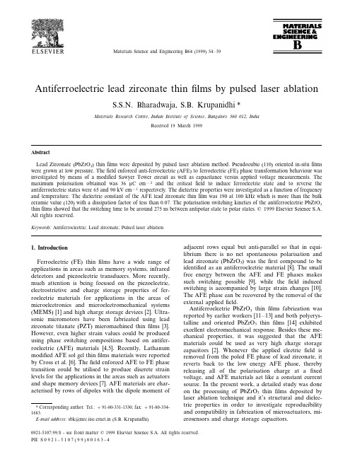
Materials Science and Engineering B64(1999)54–59Antiferroelectric lead zirconate thinfilms by pulsed laser ablationS.S.N.Bharadwaja,S.B.Krupanidhi*Materials Research Centre,Indian Institute of Science,Bangalore560012,IndiaReceived19March1999AbstractLead Zirconate(PbZrO3)thinfilms were deposited by pulsed laser ablation method.Pseudocubic(110)oriented in-situfilms were grown at low pressure.Thefield enforced anti-ferroelectric(AFE)to ferroelectric(FE)phase transformation behaviour was investigated by means of a modified Sawyer Tower circuit as well as capacitance versus applied voltage measurements.The maximum polarisation obtained was36m C cm−2and the criticalfield to induce ferroelectric state and to reverse the antiferroelectric states were65and90kV cm−1respectively.The dielectric properties were investigated as a function of frequency and temperature.The dielectric constant of the AFE lead zirconate thinfilm was190at100kHz which is more than the bulk ceramic value(120)with a dissipation factor of less than0.07.The polarisation switching kinetics of the antiferroelectric PbZrO3 thinfilms showed that the switching time to be around275ns between antipolar state to polar states.©1999Elsevier Science S.A. All rights reserved.Keywords:Antiferroelectric;Lead zirconate;Pulsed laser ablation1.IntroductionFerroclectric(FE)thinfilms have a wide range of applications in areas such as memory systems,infrared detectors and piezoelectric transducers.More recently, much attention is being focused on the piezoelectric, electrostrictive and charge storage properties of fer-roelectric materials for applications in the areas of microelectronics and microelectromechanical systems (MEMS)[1]and high charge storage devices[2].Ultra-sonic micromotors have been fabricated using lead zirconate titanate(PZT)micromachined thinfilms[3]. However,even higher strain values could be produced using phase switching compositions based on antifer-roelectric(AFE)materials[4,5].Recently,Lathanum modified AFE sol gel thinfilms materials were reported by Cross et al.[6].Thefield enforced AFE to FE phase transition could be utilised to produce discrete strain levels for the applications in the areas such as actuators and shape memory devices[7].AFE materials are char-acterised by rows of dipoles with the dipole moment of adjacent rows equal but anti-parallel so that in equi-librium there is no net spontaneous polarisation and lead zirconate(PbZrO3)was thefirst compound to be identified as an antiferroelectric material[8].The small free energy between the AFE and FE phases makes such switching possible[9],while thefield induced switching is accompanied by large strain changes[10]. The AFE phase can be recovered by the removal of the external appliedfield.Antiferroelectric PbZrO3thinfilms fabrication was reported by earlier workers[11–13]and both polycrys-talline and oriented PbZrO3thinfilms[14]exhibited excellent electromechanical response.Besides these me-chanical properties,it was suggested that the AFE materials could be used as very high charge storage capacitors[2].Whenever the applied electricfield is removed from the poled FE phase of lead zirconate,it reverts back to the low energy AFE phase,thereby releasing all of the polarisation charge at afixed voltage,and AFE materials act like a constant current source.In the present work,a detailed study was done on the processing of PbZrO3thinfilms deposited by laser ablation technique and it’s structural and dielec-tric properties in order to investigate reproducibility and compatibility in fabrication of microactuators,mi-crosensors and charge storage capacitors.*Corresponding author.Tel.:+91-80-331-1330;fax:+91-80-334-1683.E-mail address:sbk@mrc.iisc.ernet.in(S.B.Krupanidhi)0921-5107/99/$-see front matter©1999Elsevier Science S.A.All rights reserved. PII:S0921-5107(99)00163-4S.S.N.Bharadwaja,S.B.Krupanidhi/Materials Science and Engineering B64(1999)54–59552.ExperimentalLead Zirconate thinfilms were deposited by a KrF (248nm)pulsed excimer laser system(Lambda Physik). The schematic diagram of the deposition set-up was given elsewhere[15].The laser beam at a repetition frequency of7Hz was focused using a UV grade plano-convex lens of50cm focal length and was made incident on the ceramic target through a quartz window at an angle of45°.The energyfluence on the target surface was kept in the range of3–3.5J cm−2by adjusting the laser spot size on the target.The operat-ing pressure inside the chamber was controlled precisely with a MKS massflow meter,whereas the substrate temperature was monitored with an external biased heaterfixed inside the deposition chamber.A lead zirconate target was prepared by mixing the oxides,PbO(Aldrich,99.9%)and ZrO2(Aldrich, 99.9%)in molar ratio like in the conventional solid state reaction method.The calcinated PbZrO3powder was pressed into a pellet of diameter of2in.with PVA as binder and sintered at1100°C for2h to achieve above96%of theoretical density.The structural and compositional analysis of the target was confirmed prior to deposition by X-ray diffraction technique (XRD)and energy disperse analysis of X-rays(EDAX).A copper plate was glued on the rear side of the PbZrO3target in order to avoid thermal shock effects during ablation.The front surface of the target was polished and mounted on a motor driven rotator shaft with a continuous rotation at a constant speed,to ensure uniform ablation rate during deposition. (111)Pt/TiO2/SiO2/(100)Si wafers were cleanedfirstly with boiled water and then with isopropanol and they were then placed parallel to the target at a distance of 3cm on a substrate holder with a mechanical clamping system.The temperature of the substrate was controlled by means of an external voltage regulator.The lead zirconate thinfilms were deposited around550°C with various oxygen partial pressures.The structure of the films was confirmed by XRD.The microstructures and chemical composition of thefilms were examined by means of SEM and EDAX,respectively.To study the electrical and dielectric properties,gold electrodes with a radius of0.4mm were deposited on the top surface of thefilms by means of an evaporation technique.The dielectric properties were investigated at different temperatures by a computer controlled Keith-ley3000LCZ meter in conjunction with a Eurotherm temperature controller.The hysteresis properties were studied by a utilizing modified Sawyer Tower circuit. The switching kinetics of AFE lead zirconate was also investigated in order to evaluate the switching speed of field induced transition between AFE and FE phases.3.Results and discussion3.1.Structure and morphologyLead Zirconatefilms were deposited on Pt coated Si substrates.Fig.1shows the X-ray diffraction pattern for thefilms deposited at different pressures with a repetition rate of7Hz and3–3.5J cm−2fluence on the target for30min.Thefilm thickness was determined by means of cross sectional SEM and verified by stylus method and was found to be around1.0m m.At a low pressure of10mTorr,thefilms showed initiation of perovskite peaks with very less intensity of main peaks. As the pressure was increased to50mTorr,the peak intensities increased and further increase in the partial pressure to100mTorr tends to show a dominant pyrochlore phase along with perovskite phase.As the pressure was increased from50to100mTorr the scattering of cationic species also increased which in turn,led to off-stoichiometric cationic ratio in thefilms, thus leading to the dominance of the pyrochlore phase. At a very low pressure like10mTorr the oxidation of the cationic species matters in the enhancement of the perovskite phase.Earlier workers reported this type of behaviour in he case of pulsed excimer laser deposition of PZTfilms[16].The semi-quantitative analysis also revealed that the cationic ratio deviated from the stoi-chiometric ratio(1:1)in thefilms deposited at10and 100mTorr.Films deposited25°C below and25°C above550°C also showed only pyrochlore phase.This Fig.1.X-ray diffraction pattern of in-situ grown lead zirconate thin films with a substrate temperature of550°C,(a)10mTorr,(b)50 mTorr,(c)100mTorr.S.S.N.Bharadwaja,S.B.Krupanidhi/Materials Science and Engineering B64(1999)54–59 56Fig.2.(a)Scanning electron micrographs of surface image of lead zirconate thinfilm deposited at550°C with50mTorr.(b)Scanning electron micrograph of cross sectional image of lead zirconate thin film deposited at550°C with50mTorr.Fig.3.Dielectric constant and loss factor dispersion with frequency at room temperature.at100kHz and did not show much dispersion with frequency.This value was little higher than the bulk value( 120)reported by Cross et al.[17].The dielec-tric constant of the stoichiometric lead zirconatefilms showed a temperature dependent broad phase transi-tion around235°C,which is very close to the bulk crystal( 230°C),[8]as shown in Fig.4.The observed broadness of the peak and the higher transition temper-ature than the bulk ceramic could be attributed to either:(1)the stress betweenfilm and electrodes;(2) defects such as Pb vacancies and/or oxygen vacancies,explains that optimal operating parameters are very much necessary to get reproducible100%perovskite phase in the PvZrO3films and thefilms that were deposited at550°C with50mTorr were taken to study dielectric properties of the same,while this set of growth condition offered stoichiometricfilms.Fig.2(a)and(b)show the SEM data of the surface and cross sectional features of thefilm deposited at a temperature of550°C with50mTorr pressure.The micrographs of thefilm showed a very dense,fine grained columnar structure with less number of particu-lates.Micrographs of thefilms that were deposited at 10and100mTorr showed notable discontinuities with off stoichiometry in cationic ratio which was also re-vealed earlier from the XRD patterns.3.2.Electrical propertiesThe variation in the dielectric constant(K)and dissi-pation(tan d)factor were measured with50mV oscilla-tion level for1.0m m PbZrO3films deposited at550°C is shown in Fig.3.The dielectric constant was above190Fig. 4.Variation of dielectric constant with temperature in lead zirconate thinfilm.S .S .N .Bharadwaja ,S .B .Krupanidhi /Materials Science and Engineering B 64(1999)54–5957Fig.5.Polarisation versus voltage hysteresis behaviour of anti ferroelectric lead zirconate thin film.The thickness of the film is 1m m.associated with the film during deposition;or (3)to the finer grain size of the films or combinations of all the above mentioned factors.3.3.Hysteresis beha 6iourThe polarisation–voltage (P–V)measurements were done using a computer automated modified Sawyer Tower circuit on the lead zirconate thin films and results were shown in Fig.5.The forward AFE [FE and backward switching FE [AFE fields were 64and 90kV cm −1respectively.The saturated polarisation was 36m C cm −2which was a comparable to that reported by earlier workers [18,19].This behaviour confirmed the presence of the AFE phase in the laser ablated PbZrO 3films.The other way to demonstrate phase switching in the antiferroelectric material is by recording the variation of the capacitance of the film as a function of the d.c.bias.The change in the polarisation of a polar material with the applied electric field changes the dielectric constant as follows.K h(P(1)where K is the dielectric constant of the materials and (#P /#E )is the polarisation change with the change in the d.c.field.For a constant geometrical factor,(m 0A )/d (where m 0is the permitivity of the free space,A is the electrode area,d is the thickness of the film),the capacitance is proportional to the dielectric constant of the material.Thus,the typical capacitance versus voltage (C–V)curve for an AFE composition exhibits a double peak butterfly type characteristics [2].The capacitance variation with the d.c.field is shown in the Fig.6.the observation of ‘double butterfly’loop in the C–V curve clearly establishes the evidence for the field induced ferroelectric transition in the AFE leadzirconate films.The values of forward AFE [FE (E AFE )switching field and backward FE [AFE (E FE )switching field are 64and 90kV cm −1respectively and may be found in concurrence with the values observed from the P–V double hysteresis loop.The asymmetry in E AFE and E FE values in the forward and reverse directions might be attributed to:(1)the differences in work functions between top and bottom surfaces of the films,there by leading to the formation of the space charge layer between the electrode and the film sur-faces;(2)the lateral mechanical interaction between the film and the substrate which leads to a 2-D clamping effect of the dipoles [20];and (3)the growth and /or nucleation of ferroelectric and ferroelastic domain wall reorientations in the grain remains because of the possi-ble presence of space charges at the grain boundaries.Fig.6.Capacitance versus applied voltage in lead zirconate thin film.S.S.N.Bharadwaja,S.B.Krupanidhi/Materials Science and Engineering B64(1999)54–59 583.4.D.C.leakage propertiesIt is worth understanding the leakage current mecha-nism through the antiferroelectric PbZrO3thinfilms,since the leakage current directly effects the chargestorage in these materials.The leakage current mecha-nism can be explained by the following relation[21];I8V n(2)for a dielectric slab in between two electrodes,where Iis the current density and V is the applied voltage.Thevalue of the exponent varies depending up on thefieldstrength and microstructural inhomogeneities in thefilms.In lower voltage regime there is a linear relation-ship between leakage current and the d.c.bias,whichfalls under ohmic region.The ohmic regime is given byI8V(3)i.e.for n=1,the leakage current varies linearly with theapplied d.c.voltage,which is generally observed in thelow voltage regime,like in many other dielectrics.For,although at any voltage V,however small,there will beexcess charge injected into the insulator,from impuri-ties and structural defects present in thefilm.Thesecharged species excite into the conduction band even atlower voltages and are responsible for the leakagecurrent.For the values of n higher than1the leakagecurrent varies non-linearly with the applied d.c.stressand if the dielectric possesses discrete traps with differ-ent activation energies it follows space charge limitedconduction(SCLC)given by[22];I8V(s+1)d(2s+1)(4)where s=T t/T and d is the thickness of thefilm,T t is a temperature parameter characterising the trap distribu-tion and T is the absolute temperature.Fig.7shows the log I−log V characteristics of AFE lead zirconate thin films sandwiched between the Au and the Pt electrode. It may be seen that at lower temperatures(30–50°C) there was a sudden jump to the higher order in the magnitude of the current.As the temperature was increased to above a certain critical temperature,the abruptness in the change of order slowly vanished and followed a non-linear curvature.At higher temperature and higher voltages,the curves are showing a slope of approximately2,which means the current conduction mechanism through these PbZrO3thinfilms follow a square law.At higher voltages all the curves are merg-ing with one another this in turn indicates that the temperature does not have a critical role on the conduc-tion mechanism,and is in concurrence with the Space Charge Limited Conduction theory.The sudden shoot-ing up in the current below certain characteristic tem-perature in lowfield regime could be attributed to the releasing of certain discrete inherent traps with lesser Fig.7.Log current−log voltage(log I−log V)curves measured for lead zirconate thinfilms.activation energy as shallow traps present are in the film.As the temperature increased to above that char-acteristic temperature,the onset of distributed trap space charge limited conduction(SCLC)was holding in the moderate and highfield regimes.Further detailed studies are required to confirm this type of behaviour with thefilms of different thickness’which are in progress.3.5.Field induced switching kinetics from AFE to FE phaseAnother important parameter worth studying in the AFE thinfilms for microactuator applications is the switching speed offield induced phase transition be-tween the AFE to FE phases.In Fig.8,the second current maximum shows the switching behaviour of PbZrO3thinfilms under voltage pulses.The initial peak is the surge of capacitor at the time offield applied.The switching time is defined as the time at which the current decreases to10%of the value at the second maximum[23].With the applied signal voltage in-creased(see Fig.8),the switching time also increased. The shift in the discharge peak(first peak)with the voltage increase might be due to d.c.stress between the film and the electrode surfaces and/or the accumulation of the space charges between the electrode and thefilm. The switching time betweenfield induced FE to AFE phases was found to be about275ns,which was much less when compared to the speed offield induced transi-tion in the bulk La-modified antiferroelectric ceramics ( 2m s)[24]and comparable to that reported forS .S .N .Bharadwaja ,S .B .Krupanidhi /Materials Science and Engineering B 64(1999)54–5959Fig.8.Room temperature switching characteristics in lead zirconate thin films.AcknowledgementsAuthors acknowledge the financial support from De-partment of Science and Technology to carry out the present work.One of the authors (SSNB )also acknowl-edges UGC for the financial assistance.References[1]D.L.Polla,Microelec.Eng.29(1995)51–58.[2]B.Jaffe,Proc.of the IRE,(1960)1264–1267.[3]K.R.Udayakumar,J.Chen,K.G.Brooks,L.E.Cross,A.M.Flymn,D.J.Ehrlich,Mater.Res.Soc.Symp.Proc.49(1992)243.[4]W.Y.Pan,C.Q.Dam,Q.M.Zhang,L.E.Cross,J.Appl.Phys.66(1989)6014.[5]W.Pan,Q.Zhang,A.Bhalla,L.E.Cross,J.Am.Ceram.Soc.72(1998)571–578.[6]K.G.Brooks,J.Chen,K.R.Udayakumar,L.E.Cross,J.Appl.Phys.75(1994)1699.[7]K.Uchino,Proc.of the Materials Research Society Internationalmetting on Advanced Materials,vol.9,MRS,1989pp.489–503.[8]G.Shirane,S.Swaguchio,T.Tokagi,Phy.Rev.B 84(1951)476.[9]D.Berlincourt,IEEE Trans.Sonics Ultrason.SU-13(1966)116.[10]D.Berlincourt,H.H.A.Krueger,B.Jaffe,J.Phys.Chem.Solids.25(1964)659–674.[11]T.Tani,J.F.Li,D.Viehland,D.A.Payne,J.Appl.Phys.75(1994)3017.[12]K.Yamakawa,S.Trolier-McKinstry,J.P.Dougherty,S.B.Kru-panidhi,Appl.Phys.Lett.67(1995)2014.[13]K.D.Budd,S.K.Dey,D.A.Payne,Br.Ceram.Soc.Proc.36(1985)107.[14]K.Yamakawa,S.Trolier-McKinstry,J.P.Dougherty,Proc.ofthe 10th IEEE International Symposium of the Application of Ferroelectrics (ISAF 96),vol.II,1996,405–408.[15]S.B Krupanidhi,J.Vac.Sci.Tech.A 10(1992)1569.[16]D.Roy,S.B.Kruapnidhi,J.Mater.Res.7(1992)2521–2529.[17]M.J.Haun,T.J.Harvin,nagan,Z.Q.Zhuang,S.J.J.ang,L.E.Cross,J.Appl.Phys.65(1989)3173.[18]K.K.Li,F.Wang,G.H.Haertling,J.Mater.Sci.30(1995)1386.[19]T.Tani,J.F.Li,D.Viehland,D.A.Payne,J.Appl.Phys.75(1994)3017.[20]N.A.Pertsev,A.G.Zembilgotov,A.K.Tagantsev,Phys.Rev.Lett.80(1998)1988.[21]J.J.O’Dwyer,The theory of Electrical Conduction and Break-down in Solid Dielectrics,Clarendon Press,Oxford,1973.[22]mpert,P.Mark,Current Injection In Solids,AcademicPress,New York,1970.[23]W.Mertz,Phy.Rev.95(1954)690.[24]W.Y.Pan,W.Y.Gu,L.E.Cross,Ferroelectrics 99(1989)185–194.[25]K.G.Brooks,J.Chen,K.R.Udayakumar,L.E.Cross,J.Appl.Phys.75(1994)1699.sol-gel thin films [25].The kinetics is controlled by nucle-ation of new domains,grain size and defects present in the films.Further studies are in progress with the varia-tion of the film thickness,electrode padding to gain fur-ther understanding.4.ConclusionsIn-situ antiferroelectric (AFE)lead zirconate (PbZrO 3)thin films were successfully fabricated using pulsed laser ablation at a low pressure.PbZrO 3thin films with pseu-docubic (110)orientation were prepared on Pt coated Si substrate with TiO 2buffer layer.Films exhibited a dielectric constant of 190at 100kHz frequency.The field enforced ferroelectric (FE)–antiferroelectric (AFE)transition was confirmed at room temperature,both in polarisation versus voltage (P–V)and capaci-tance versus voltage (C–V)curves.The maximum polar-isation obtained was 36m C cm −2and the energies required for the both forward AFE [FE and backward FE [AFE switching field was 64and 90kV cm −1respectively.The switching time of field induced transi-tion between AFE and FE phase was about 275ns..。
陶瓷英文怎么说

陶瓷英文怎么说用陶土烧制的器皿叫陶器,用瓷土烧制的器皿叫瓷器。
陶瓷则是陶器,炻器和瓷器的总称。
凡是用陶土和瓷土这两种不同性质的粘土为原料,经过配料、成型、干燥、焙烧等工艺流程制成的器物都可以叫陶瓷。
那么你知道陶瓷用英语怎么说吗?下面来学习一下吧。
陶瓷的英语说法1:ceramics陶瓷的英语说法2:pottery陶瓷的相关短语:陶瓷刀 Ceramic knife ; Ceramic knives ; Ceramic blade ; cerami 金属陶瓷 cermet ; ceramic metal ; metal ceramic ; ceramal陶瓷电容 Ceramic capacitor ; MLCC ; Ceramic Disc and Plate ; Ceramic Cap陶瓷金属 Ceramic metal ; ceramal ; cermet ; ceramel陶瓷工程ceramic engineering ; ceramic works ; Ceramic Sciences and Engineering ; CeramEng高温陶瓷refractory china ; pyroceramic ; high temperature ceramics ; refractory ceramics陶瓷配件 ceramic fitting ; nbsp氧化铝陶瓷alumina ceramics ; aluminum oxide ceramics ; alumina whiteware ; corundum生物陶瓷bioceramics ; biological ceramics ; Biomedical Ceramics陶瓷的英语例句:1. Exquisite china soup dishes reposed on silver plates.银盘子上面摆放着精制的陶瓷汤盘。
2. an exhibition of ceramics by Picasso毕加索陶瓷作品展3. Some ceramic works of art are shown in this exhibition.这次展览会上展出了一些陶瓷艺术品.4. This represents the highest achievement of Chinese ceramics.这代表了中国陶瓷的最高成就.5. Common ceramic elements are barium titanate and lead zirconate - titanate.普通的陶瓷元件分别是钛酸钡和锆钛酸铅.6. The second type is a ceramic - based coating marketed by Magnaflux Corp.第二种类型是由Magnaflux公司出售的一种陶瓷基脆性涂料.7. The main classes of materials are metals, polymers, ceramics, and composites.材料的主要分类为金属、高聚物, 陶瓷, 及合成材料.8. Ceramic elements are made by pressing and sintering finely powdered material s.陶瓷元件是将仔细研磨的材料经过加压和烧结制成.9. The first utilizes a blend of finely ground ceramic powders.第一种用的是一种磨细的陶瓷粉末混合物.10. All our glass and china is kept in the cupboard.我们所有的玻璃和陶瓷器皿都放在柜橱里.11. The roofs are covered with more than 1,056,000 Swedish made ceramic tiles in white and cream.屋顶为瑞典制造的105.6万多块陶瓷所覆盖,呈乳白色.12. Traditionally, the term " ceramic " referred to materials produced by baking moist clay to form hard solids.习惯上, “ 陶瓷” 一词是指潮湿粘土经烘焙生成的坚硬固体.13. I went over to one of the stalls and examined porcelain vases and flowered tea - sets.我走到一个货摊的前面,仔细察看着陶瓷花瓶和饰有花纹的茶具.14. Working at the wheel, the ceramist rounded out the form, and the bowl appeared finished.认真研究了轮状物后, 陶瓷技师把模具制成圆形, 后来碗就出现了.15. Development of the ferroelectric ceramics in recent years has led to superior detection ability.近代所发明的铁电陶瓷具有优良的检测能力.。
压电陶瓷的种类
压电陶瓷的种类1 铁电陶瓷ferroelecteic ceramics具有重铁电性的陶瓷称为铁电陶瓷。
从晶体结构来看,铁电陶瓷的晶体的主晶相具有钙钛矿结构,钨青铜结构,铋层状结构和焦绿石结构等。
2 反铁电陶瓷antiferroelectric ceramics具有反铁电性的陶瓷称为反铁电陶瓷。
3 压电陶瓷piezoelectric ceramics具有压电效应的陶瓷称为压电陶瓷,由于末经过极化处理的铁电陶瓷的自发极化随机取向,故没有压电性。
极化处理使其自发极化沿极化方向择优取向。
在撤去电场后,陶瓷体仍保留着一定的总体剩余极化,故使陶瓷体有了压电性,成为压电陶瓷。
在高温的高温度梯度场中定向析晶的非铁电极性玻璃陶瓷也具有压电性。
4 钛酸钡陶瓷barium titanate ceramics钛酸钡陶瓷是一种具有典型钙钛矿结构的铁电陶瓷。
它通常是以碳酸钡和二氧化钛为主要原料,预先合成后再在高温下烧结而成的。
5 钛酸铅陶瓷lead titanate ceramics钛酸铅陶瓷是具有钙钛矿性结构的铁电陶瓷。
它通常是由四氧化三铅{或氧化铅}和二氧化钛以及少量添加物预先合成后再在高温下烧结而成的。
6 二元系陶瓷binary system ceramies二元系压电陶瓷是俩种化学通式ABO3型结构的化学物所形成的固溶体,其中A 代表二价的正离子Pb2+,Ba2+,Mg2+,Ca2+,Sr2+,等或一价正离子K+,Na+等,B代表四价的正离子Zr4+,Ti4+或五价的Nb5+等。
最常见的二元系压电陶瓷是PbZrxTi{1-x}O3。
通过调节两种ABO3型结构的克分子比,以及用取代元素和添加物改性的方法,可以获得各种不同用途的材料。
7 锆钛酸铅陶瓷Lead zirconate ceramic锆钛酸铅陶瓷通常简称为PZT陶瓷,这种压电陶瓷目前受到广泛应用。
它是PbZrO3和PbTiO3的固溶体,具有钙钛矿型结构,当锆钛比为53/47左右{即共晶相界附近}时,具有最强的压电性能。
Ferroic Materials and Their Applications

Ferroic Materials and TheirApplicationsFerroic materials are a family of materials that exhibit ferroic properties, which include ferroelectricity, ferromagnetism, ferroelasticity, and ferrotoroidicity. These properties arise due to the spontaneous polarization or magnetization of the materials, which can be switched externally by applying an electric or magnetic field. Ferroic materials have been extensively researched and developed for various applications, ranging from electronic devices to energy storage systems. In this article, we will discuss the properties of different ferroic materials and their applications.Ferroelectric MaterialsFerroelectric materials are materials that exhibit a spontaneous polarization, which can be reversed by applying an electric field. The most widely studied ferroelectric materials are perovskite oxides, such as lead zirconate titanate (PZT) and barium titanate (BaTiO3). These materials have been used in various applications, including capacitors, sensors, actuators, and memory devices.Capacitors made of ferroelectric materials have high dielectric constants, which can be exploited in various electronic and communication applications. Ferroelectric sensors and actuators are used to detect and control mechanical vibrations, pressure, temperature, and other physical parameters. Ferroelectric memory devices, such as ferroelectric random access memory (FeRAM), offer non-volatile, high-speed, and low-power data storage, which can be used in portable devices and smart cards.Ferromagnetic MaterialsFerromagnetic materials are materials that exhibit a spontaneous magnetization, which can be reversed by applying a magnetic field. The most widely studied ferromagnetic materials are transition metal alloys, such as iron, cobalt, and nickel, andtheir oxides and ferrites. These materials have been used in various applications, including magnetic storage, magnetic sensors, and spintronics.Magnetic storage devices, such as hard disk drives and magnetic tapes, use ferromagnetic materials to store and retrieve digital data. Magnetic sensors, such as magnetic field sensors and magnetometers, use ferromagnetic materials to detect magnetic fields and measure their strength and direction. Spintronics is an emerging field that uses the spin of electrons in ferromagnetic materials to manipulate and control the flow of electric current, which can be used in high-speed and low-power computing and communication devices.Ferroelastic MaterialsFerroelastic materials are materials that exhibit a spontaneous strain, which can be reversed by applying a mechanical stress. The most widely studied ferroelastic materials are shape memory alloys, such as nickel-titanium (NiTi) and copper-aluminum-nickel (CuAlNi) alloys. These materials have been used in various applications, including biomedical implants, aerospace components, and smart structures.Biomedical implants made of shape memory alloys can adapt to the shape and size of the living tissues, which can reduce the risk of rejection and improve the healing process. Aerospace components made of shape memory alloys can withstand extreme temperatures and deformations, which can improve the safety and reliability of the aircraft. Smart structures made of shape memory alloys can change their shape and stiffness in response to external stimuli, which can be used in robotics, mechatronics, and civil engineering.Ferrotoroidic MaterialsFerrotoroidic materials are materials that exhibit a spontaneous toroidal moment, which can be reversed by applying an electric or magnetic field. The most widely studied ferrotoroidic materials are multiferroic materials, which exhibit both ferroelectric and ferromagnetic properties, such as BiFeO3 and YMnO3. These materials have been used in various applications, including data storage, spintronics, and magnetoelectric devices.Data storage devices made of multiferroic materials can store and retrieve digital data using both electric and magnetic fields, which can improve the speed and energy efficiency of the devices. Spintronics devices made of multiferroic materials can manipulate and control the spin of electrons using both electric and magnetic fields, which can be used in high-speed and low-power computing and communication devices. Magnetoelectric devices made of multiferroic materials can convert between electric and magnetic fields, which can be used in energy harvesting, sensing, and actuation.ConclusionFerroic materials are a family of materials that exhibit some unique properties, such as ferroelectricity, ferromagnetism, ferroelasticity, and ferrotoroidicity. These properties have been extensively researched and developed for various applications, ranging from electronic devices to energy storage systems. The discovery and development of new ferroic materials and their applications will continue to push the boundaries of science and technology, and improve our daily lives.。
不同厚度PZT薄膜的制备及电性能特性研究
不同厚度PZT薄膜的制备及电性能特性研究宋瑞佳;郑俊华;谭秋林【摘要】采用sol-gel(溶胶-凝胶)法在Pt/Ti/SiO2/Si基底上分别制备了厚度为400 nm、600 nm、800 nm的PZT(锆钛酸铅,Zr/Ti=52/48)薄膜,研究了厚度对薄膜介电性能与铁电性能的影响。
通过对薄膜的铁电性能与介电性能进行测试,分析了不同厚度薄膜的剩余极化强度、介电常数与介电损耗,进一步分析了薄膜的介电调谐性能。
实验结果表明,薄膜的介电常数与介电损耗随薄膜厚度的增大而增加;厚度为600 nm的薄膜具有最好的介电调谐性能与铁电性能。
%PZT(Lead Zirconate Titanate,Zr/Ti=52/48)thin films with a thickness of 400 nm,600 nm and 800 nm were prepared by sol-gel method on Pt/Ti/SiO2/Si substrates,the electrical properties and ferroelectric properties of the PZT thin films with different thickness was researched. We tested the dielectric properties and ferroelectric properties and analyzed the remnant polarization,dielectric constant and dielectric loss of the PZT thin films with different thickness and further analyzed the dielectric tunable properties of thin films. The experimental results showed that the dielectric constant and dielectric loss increase with the increase of film thickness ,and the thickness of 600 nm film has the best dielectric tunable properties of ferroelectric properties.【期刊名称】《电子器件》【年(卷),期】2016(039)005【总页数】3页(P1034-1036)【关键词】铁电薄膜;PZT薄膜;溶胶-凝胶;介电性;铁电性【作者】宋瑞佳;郑俊华;谭秋林【作者单位】中北大学电子测试技术国家重点实验室,太原030051; 中北大学仪器科学与动态测试教育部重点实验室,太原030051;中北大学电子测试技术国家重点实验室,太原030051; 中北大学仪器科学与动态测试教育部重点实验室,太原030051;中北大学电子测试技术国家重点实验室,太原030051; 中北大学仪器科学与动态测试教育部重点实验室,太原030051【正文语种】中文【中图分类】TF123;TM282铅基薄膜如PT、PCT、PLT和PZT等,由于具有优良的介电、铁电及热释电性能,成为当前国际上备受关注的功能材料,被广泛应用于制备热成像器件、热释电红外传感器、MEMS器件和铁电随机存储器等[1-4]。
新材料词汇中英对照
·中英文新材料词汇白刚玉微粉white fused alumina powder白色光固化字符印料light solidified white symbol ink半导体超晶格材料semiconductor super lattic materials保偏光纤polarization maintaining fiber钡铁氧体磁粉Ba-ferrite powder标准单模光纤standard single mode fiber; G.625 fiber表面保护压敏粘胶带surface protect pressure sensitive adhesive tape表面组装用胶粘剂surface mounting adhesives冰醋酸acatic acid glacial丙酮acetone波峰焊剂soldering flux of wave crest玻璃纤维增强环氧膜塑料glass fiber reinforced epoxy molding薄钢带thin steel strip薄膜磁头及磁芯材料thin film magnetic heads and their cores彩色液晶colour liquid crystals蚕丝筛网natural silk bolting cloth插件胶adhesive for inserting electronic掺铥钇铝石榴石激光晶体Tm-doped YAG crystal掺铒磷酸盐激光玻璃erbium-doped phosphate glass掺铒钇铝石榴石激光晶体Er-doped YAG laser crystal掺铬氟铝锶锂氟铝钙锂可协调激光晶体/Cr-doped LiSrAlF6/LiCaAlF6 tunable laser crystal掺铬镁橄榄石晶体Cr-doped forsterite crystal掺钬、铥、铬钇铝石榴石激光晶体Ho,Tm,Cr-doped YAG laser crystal掺钬、铒、铥氟化钇锂激光晶体Ho,Er,Tm-doped YLF laser ctystal掺钕、铈、铬钇铝石榴石激光晶体Nd,Ce,Cr-doped YAG laser掺钕、铈、铽钇铝石榴石激光晶体Nd,Ce,Tb-doped YAG laser crystal掺钕掺四价铬钇铝石榴石晶体Nd, Cr-doped YAG crystal掺钕掺氧化镁铌酸锂晶体neodymium and magnesium oxide掺钕钒酸激光晶体Nd-doped YVO4 laser crystal掺钕氟化钇锂激光晶体Nd-doped YLF laser crystal掺钕铝酸钇激光晶体Nd-doped YAP laser ctystal掺钕钇铝石榴石激光晶体Nd-doped YAG laser crystal掺铈的硅酸钆闪烁晶体cerium activated scintillater掺四价铬钇铝石榴石激光晶体Cr4+-doped YAG crystal掺铁铌酸锂晶体iron dopen lithium niobate ctystal掺氧化镁铌酸锂晶体magnesium oxide doped lithium niobate crystal掺氧化锌铌酸锂晶体zinc oxide doped lithium niobate crystal掺镱钇铝石榴石激光晶体Yb- YAG laser crystal超长铜芯聚酯带super-long copper core polyester tape超细钯粉ultrafine palladium powder超细玻璃粉palladium powder超细箔粉ultrafine platinum powder超细二氧化钌粉ultrafine ruthenium oxide powder超细金粉ultrafine gold powder超细镍粉ultrafine nickel powder超细铜粉ultrafine copper powder超细银钯合金粉ultrafine silver-palladium powder超细银铋合金粉ultrafine silver-bismuth powder超细银粉ultrafine silver powder传输光纤transmission fiber纯六氟化钼pure molybdenum hexafluoride纯氖pure neon纯一氧化氮pure nitric oxide瓷基有机覆铜板ceramic organic base copper clad laminate磁粉magnetic powder磁温度补偿合金magnetic temperature compensate alloy磁性液体magnetic fluid氮化镓外延材料gallium nitride epitaxial materials导电布conduction cloth导电聚苯乙烯塑料conductive high impact polustylene导电聚丙烯condutive polypropylene导电聚乙烯condutive poliethylene灯用三基色荧光粉the phosphor of rare-earth低固免清洗助焊剂soldering flux of low solid and free cleaning低温封接玻璃粉low-meiting sealing frils低温合金钎料solders of low melting point alloys涤纶薄膜电容器内包封料inside encapsulate compound for terylene film condenser涤纶薄膜电容器外包封料outside encapsulate compound for terylene film condenser涤纶丝筛网terylene fibre bolting cloth碲镉汞晶体mercury cadmium telluride(MCT) ctystal碲化铅单晶lead telluride碲锌镉衬底材料cadmium zinc tellutide substrate material电弧石英玻璃坩埚arc quartz glass crucibles电压穿透式多色荧光粉voltage penetration multicolor phosphor电子灌封料electronic potting resin电子级八氟丙烷octafluoropropane, electronic grade; perfluoropropane, electronic grade; halocarbon 218, electronic grade电子级二氯二氢硅dichlororosilane eiectronic grade电子束负性抗蚀剂electron-beam negative photoresist电子束正性抗蚀剂electron-beam positive photoresist电子元件固定密封胶sealant for set electronic companents电子专用热粘胶带hot melt masking tape丁酮butanone杜美丝dumet wire镀锡铜包钢线copper-tinlead wire; CP wire二甲苯xylene二氯甲烷dichloromethane二氧化碲单晶tellurium dioxide single crystal二氧化硅silicon dioxide二氧化硫sulohur dioxide发泡镍合金丝bubbing nickel alloy wire钒酸钇单晶yttrium vanadate single crystal防氧化焊锡条oxidation preventive tin solder wires防氧化特种焊条special solder for oxidation resistance防氧化助焊剂antioxidizing solding aid仿金刚石晶体膜diamond like coatings, DLC非晶磁头材料amorphous magnetic head materials非晶硅薄膜amorphous silicon film非晶态磁光薄膜amorphous magneto-optical thin films非晶态磁头薄膜amorphous magneto-optical thin films非晶态磁头材料amorphous magnetic alloys for magnetic head非晶态软磁合金amorphous soft magnetic alloys非零色散位移单模光纤non-zero dispersion shifted dingle mode fiber; G.655fiber非蒸散型吸气剂non-evaporable getter氟化铵溶液ammonium fluoride solution氟化钡barium fluoride氟化钙celeium fluoride氟化镁magnesium fluoride氟化镁magnesium fluoride氟化镁钾:锰potassium Magnesium fluoride activated by managanese氟化铅lead fluorede氟锗酸镁:锰magnesium fluorogermanate activated by manganese负胶漂洗液wash liquid for negative resist负胶显影液developer for negative photoresist负温度系数热敏电阻陶瓷negative temperature constant thermosensitive ceramics ; NTC thermosensitive ceramics覆不锈钢箔层压板stainlass steel clad laminate覆超厚铜箔层压板super-thick copper clad laminate覆电阻箔层压板resistance foil clad laminate覆铝箔层压板aluminum clad laminate覆镍铜带capper strip coated with nickel覆铍青铜箔层压板copper containing beryllium clad laminate覆铜箔、铝箔层压板aluminum foil copper clad laminate覆铜箔酚醛纸层压板phenolic cellulose paper copper clad laminate覆铜箔复合基层压板composite copper clad laminate覆铜箔改性聚苯醚玻璃布层压板modified polyhenylene oxide resin woven glass fabric copper clad laminate覆铜箔环氧玻璃布层压板epoxide woven glass fabric copper clad laminate覆铜箔环氧纸层压板epoxide cellulose paper copper clad laminate覆铜箔聚四氟乙烯玻璃布层压板PTEE woven glass fabric copper clad laminate覆铜箔聚酰亚胺玻璃布层压板polyimide resin woven glass fabric copper clad laminate覆铜箔聚酰亚胺芳纶布基层压板polyimide resin woven aromatic polyamide fibre clad laminate覆锡铈合金铜质带材copper strip coated with tin-cerium alloy高饱和磁感应强度铁氧体high Bs ferrite高纯氨high purity ammonia高纯氮high purity nitrogen高纯二甲基镉high purity dimethylcadmium高纯二氧化碳high purity carbon dioxide高纯二乙基碲high purity diethyltellurium高纯二乙基锌high purity diethylzinc高纯氟化氢hydrogen fluoride高纯硅烷high purity silicane高纯氦high purity helium高纯甲烷high purity methane高纯氪high purity kryton高纯磷烷high purity phosphine高纯硫化氢high purity hydrogen sulfide高纯六氟化硫high purity sulphur hexafluoride高纯六氟化钨high purity tungsten hexafluoride高纯六氟乙烷high purity hexafluroethane高纯铝带、箔strip &foil of high-purity aluminium 高纯铝线high-purity aluminium wire高纯氯high purity chlorine高纯氯化氢high purity hydrogen chloride高纯氢high purity hydrogen高纯三氟化氮high purity nitrogen trifluoride高纯三氟化磷high purity phosphorus trifluoride高纯三氟化硼high purity boron trifluoride高纯三氟化砷high purity arsenic trifluoride高纯三氟甲烷trifluoromethane高纯三甲基镓high purity trimethylgallium高纯三甲基铝high purity trimethylaluminum高纯三甲基锑high purity trimethylstibine高纯三甲基铟high purity trimethylinduum高纯三氯化硼high purity trichloride高纯三氯氢硅trichlorosilane高纯三乙基铝high purity triethyl aluminum高纯疝high purity xenon高纯砷烷high purity arsine高纯四氟化硅high purity silicon tetrafluoide高纯四氟化钛high purity titanium tetrafluoride高纯四氟化碳silicon tetrachloride高纯四氯化硅silicon tetrachloride高纯四氯化硅Ⅳsuper-purity silicon tetrachlonide ; tetrachlorosilane; silicon( ) chloride高纯溴化氢high purity hydrogan bromide高纯氩high purity argon高纯氧high purity oxygen高纯氧化亚氮high purity nitrous oxide高纯一氧化碳high purity carbon monoxide高纯乙硅烷high purity disilane高纯乙硼烷high purity diborane高功率低温度系数石榴石材料系列/high power and low temperature coefficient garnet material series高介电常数覆铜板high dielectric constant copper clad laminate高频镍锌铁氧体high frequency NiZn ferrite高强度铝焊丝high strength aluminium brazing wire高性能多用焊锡丝universal tin solder wire with high preformance锆钛酸铅镧电光陶瓷lead lanthanum zirconate titanate (PLZT) electrooptical ceramics锆钛酸铅热释电陶瓷lead zirconate titanate (PZT) pyroelectric ceramics锆钛酸铅压电陶瓷lead titanate-zirconate piezoslsctric ceramic工业纯铁industrial pure iron光固化助焊剂(单组分)light solidified antiwelding agent (single components)光固化助焊剂(双组分)light solidified antiwelding agent (two components)光敏胶photosensitive光纤硅涂料silicone coating materials for optical fiber光学级晶体铌酸锂晶体optic lithium niobate crystal光学级坦酸锂晶体optic lithium niobate crystal光学石英玻璃optical quartz glass; optical quartz sheep硅单晶monocrystalline silicon硅单晶抛光片monocrystalline silicon polished wafer硅多晶policrystalline silicon硅铝合金带、箔aluminium-silicon alloy strip & fuil硅酸铋单晶bismuth silicate single crystal; BSO; bismuth silicon oxide硅酸钙:铅、锰calcium silicate activated by lead and manganese硅酸镓镧lanthanum gallium silicate single硅酸锌:锰zinc orthosilicate activated by manganese硅外延材料silicon epitaxy material硅微粉silica micropowder过氧化氢hydrogen peroxide焊料防氧化油oxidation-resistant oil for solder焊锡膏solder pastes合成石英玻璃synthetic quartz黑碳化硅涂附磨具专用微粉specid black silicon cabide powder for coated abrasive products红宝石激光晶体ruby laser crystal红色荧光粉硫氧化钇:铕(Ⅲ)-red phosphor for color TV-pigmented yttrium oxysulfide : europium phosphor红色荧光粉硫氧化钇:铕(Ⅲ)-red phosphor for color display tube-pigmented yttrium oxysulfide: europium红色荧光粉硼酸钇钆:铕(Ⅲ)-red phosphor for plasma display panel-yttrium-gadolinium borate activated by europium厚膜导体浆料thick film conductor pastes厚膜电阻浆料thick film resistance pastes厚膜介质浆料thick film dielectric paste滑石陶瓷steatite ceramics环保型阻燃环氧灌封料flame retardant and harmless to environment type of epoxy potting compound环化聚异戊二烯橡胶负性光刻胶cyclized polyisoprene rubber negative photoresist; ultraviolet negative photoresist环己烷cyclohexane环氧密封胶(单祖分)one component epoxy sealant环氧膜塑料-[1]epoxy molding compound环氧膜塑料-[2]epoxy molding compound环氧树脂diglycidyl 4,5-epoxy-tetrahydrophthalic ester环氧树脂浇铸料(光电产品用)epoxy resin casting compound (for photoelectric devices)活化剂activator活性焊剂active solder活性焊锡丝active solder wire活性松香焊锡丝activated rosin cored tin solder wire加成型硅橡胶ARCsilicone rubber ARC (additive type )加成型液体硅橡胶(单组分)additional liquid silicone rubber (one component)加速剂accelerator甲苯toluene甲醇methanol尖晶石spinel; magnesium aluminate碱性清洗液alkaline cleaner碱性蚀刻剂alkaline etchant键垫用导电硅橡胶混炼胶electically conductive silicone rubber cornpounds for key pad键合硅铝丝aluminium-silicon bonding wire键合金丝gold bonding wire胶粘剂adhesive焦磷酸锶:铕strontium pyrophosphate activated by europium结晶型低温封接玻璃粉devitrifiable low-meiting sealing frits介质陶瓷材料dielectric ceramic materials金箔gold foil金红石瓷rutile porcelain , rutile ceramics金属薄膜metal thin films金属磁粉metal magnetic powder金属基(芯)覆铜箔板metal base(core) copper clad laminate金属丝筛网metal wire bolting cloth浸涂防粘隔离剂antisticking agent晶体清洗剂crystal cleaning agent晶体粘合剂crystal adhesise局部镀银铜带capper strip coated with argentum in part聚氨酯封装料urethane potting resin聚氨酯无蜡抛光软垫polyurethane waxless polishing pad; waxless polishing pad聚酰亚胺涂层胶polyimide coatings聚乙烯醇肉桂酸酯光刻胶polyvinyl cinnamate photoresist ;1# photoresist聚脂胶粘带polyester film tape聚酯型光刻胶polyester photoresist康铜极薄带材constantan foil可伐合金kover宽频带镍铜锌系铁氧体broad band NiCuZn series ferrite蓝色荧光粉硫化锌:银-blue Phosphor For Color TV Tube-Pigmented Zinc sulfide activated by silver蓝色荧光粉硫化锌:银、铝-blue phosphor for color display tube-zinc sulfide activated by silver and aluminum蓝色荧光粉铝酸钡锶:铕(Ⅱ)Ⅱ-blue phosphor for plasma display panel-barium magnesium aluminate activated by europium()镧锆钛酸铅陶瓷lead lanthanum titanate (PLZT) ceramics锂铁氧体材料系列Li ferrite material series磷化镓单晶gallium phosphide monocrystal磷化铟单晶indium phosphide monocrustal磷化铟外延材料indium phosphide epitaxy materials磷酸phosphoric acid磷酸镓单晶gallium phosphate single crystal; gallium orthophosphate磷酸锌锶:锡、zincstrontium phosphate activated by tin磷酸氧钛钾晶体potassium titanyl phosphate crystal; KTP crystal零色散位移单模光纤zero dispersion shifted single mode fiber; G.653fiber硫化锌:铜zinc sulfide activated by copper硫化锌:铜、氯Zinc sulfide activated by copper and chlorine硫化锌:银zinc sulfide activated by silver硫化锌镉:铜zinc cadmium sulfide activated by cooper硫酸sulphuric acid硫酸钇:铈Ⅲyttrium silicate activated by cerium()六方硫化锌:银hex Zinc sulfide activated by silver六方铝酸镁镧钕晶体lanthanum magnesium hexaaluminate卤磷酸钙:锑锰.calcium halophosphate activated by antimony and manganese滤色膜用彩色树脂浆colour polymer for manufacture of color filter铝硅铁粉芯AlSiFe magnetic core铝镍钴永磁permanent magnet AINiCo铝镍钴永磁体AlNiCo permanent magnet铝镍永磁体AlNi permanent magnet铝酸镧单晶lanthanum aluminate single crystal铝酸镁单晶magnesium aluminate single crystal绿色荧光粉green phosphor for plasma display panel绿色荧光粉硫氧化锌:铜、铝-green phosphor for color TV tube-zinc sulfide activated by copper and aluminum绿色荧光粉硫氧化锌:铜、铝-green phosphor for color display tube-zinc sulfide activated by copper and aluminum绿碳化硅微粉green silicon carbide powder镁橄榄石瓷forsterite porcelain镁锌铁氧体MgZn ferrite锰白铜丝constantan wire锰锌铁氧体Mn-Zn ferrite锰锌系铁氧体材料高磁导率锰锌铁氧体μhigh i MnZn ferrite弥散强化无氧铜dispersion strengthened copper oxygen免清洗波峰焊剂free cleaning soldering flux of wave crest免清洗焊锡丝no clean solder wire免清洗助焊剂free-clean soldering flux抹音磁头环氧灌封料potting material for sound removing magnetic head of recoder ; ZM potting material钼板molybdenum sheet钼箔molybdenum foil钼封接玻璃粉molybdenum sealing glass powder钼丝molybdenum wire钼酸铅单晶lead molybdate single crystal钼钨合金丝molybdenum-tungsten alloy wire内导电石墨乳outside electric conduction graphite latices耐高温胶粘剂adhesive with high temperature resistance耐热型纸基压敏胶粘带high temperature resistance creped masking tape挠性覆铜箔材料flexible copper clad material铌酸钾晶体potassium niobate crystal; KN crystal铌酸锂单晶lithum niobate single crystal; LN铌酸锂开关Qlithium niobate Q-switch镍板nickel sheets镍带nickel strips镍合金丝nickle alloy wire镍及镍合金带nickel and nickel alloy strip镍及镍合金管nickel and nickel alloy tube镍及镍合金丝nickel and nickel alloy wire镍铁氧体材料系列Ni ferrite material series镍铁氧体高功率材料系列Ni ferrite high power material series镍铜合金nickel-copper alloy镍线nickel wire镍锌铁氧体Ni-Zn ferrite镍锌系铁氧体材料抗电磁干扰用镍铜锌系铁氧体anti-EMI NiCuZn series ferrite钕铁硼永磁NbFeB permanent magnets钕铁硼永磁粉NdFeB permanet magnetic powder钕铁硼永磁体(烧结)NdFeB magnets(sintered)喷金丝、条metal coated solders Pl38喷涂纯锌丝pure zinc wires for spraying coating硼酸镉:锰cadmium borate activated by manganese硼酸铯锂晶体cesium lithium borate crystal; CLBO crystal铍青铜箔材beryllum bronze foil铍酸镧激光晶体lanthanum beryllate laser crystal其他锰锌铁氧体other MnZn ferrite气炼石英玻璃blouing & melting quartz气炼透明石英玻璃管gas semltime quartz glass tubs气相沉积氮化硼陶瓷CVD boron nitride ceramics; PBN ceramics氢氟酸hydrofluoric acid氢氧化铵ammonium hydroxide热风整平助熔剂flux for hot air plating人造石英晶体αsynthetic quartz crystal; -SiO2软铅焊料solder三氯甲烷chloroform三氯乙烯trichloroethylene三硼酸锂晶体lithium triborate crystal; LBO crystal三元系压电陶瓷材料ternary system piezoelectric ceramic钐钴永磁粉SmCo permanet magnetic powder钐钴永磁体(烧结)SmComagnets(sintered)闪烁锗酸铋单晶scintillation bismuth germinate single crystal烧结永磁铁氧体材料sintered permanent magnet materials砷化镓单晶gallium arsenide monocrystal砷化镓外延材料gallium arsenide epitaxy material砷酸镁:锰magnesium arsenate activated by manganese石英玻璃quartz glass石英梯度型多模光纤quartz gradient type multimode fiber室温固化环氧灌封料RTV expoxy resin compound室温硫化灌封硅橡胶(双组分)RTV-2 potting and encapsulating silicone rubber室温硫化硅橡胶(单包装)RTV silicone rubber (one package)室温硫化硅橡胶(单组分)one-component RTV silicone rubber ; RTV silicone adhesives/sealants室温硫化硅橡胶(双组分)RTV silicone rubber (two components)释汞吸气剂getter mercury dispenser树脂芯焊锡丝rosin cored tin solder wires数据石英光纤data quartz fiber双向拉伸聚丙烯薄膜biaxially oriented polypropylene film水溶性光刻胶water soluble photoresist水溶性光致变色抗蚀干膜water soluble photochromatism dry photoresist水溶性焊剂water flux水溶性助焊剂water soluble soldering flux; water cleaning soldering flux丝网感光胶silk screen photosensitive emulsion丝印塑料油墨ink for plastics silk screen printing四硼酸锂单晶lithium tetraborate single ctystal; LBO塑料光纤plastic fiber酸性清洗剂acid cleaner钛宝石激光晶体Ti-doped saphire钛箔titanium foil钛酸钡热敏电阻陶瓷barium titanate thermosensitive ceramics钛酸钡铁电陶瓷barium titanate ferroelectric ceramics钛酸铅压电陶瓷lead titanate piezoelectric ceramics钽酸锂单晶lithum tantalite single crystal;LT碳化硅外延材料silicon carbide epitaxial materials碳基铁粉芯Fe-C magnetic core碳酸盐carbonate搪锡助焊剂tin coating solding aid陶瓷基无机覆铜板陶瓷基无机覆铜板ceramic inorganic base copper clad laminate特高频软磁铁氧体VHF soft magnetic ferrite特种切削液special cutting fluids锑化镓单晶gallium antimonide monocrystal锑化铟晶体indium antimonide crystal锑锰锆钛酸铅压电陶瓷lead antimony manganese zirconia titanate(SM-PZT) piezoelectric ceramics铁封接玻璃粉iron sealing glass powder铁钴钒软磁材料FeCoV soft magnetic material铁镍合金Fe-Ni alloy; permalloy铁镍钼粉芯FeNiCo magnetic core铁镍软磁合金FeNi soft magnetic alloy铁氧体永磁permanent ferrite materials通用石榴石材料系列general garnet material series铜基覆铜箔板copper base copper clad laminate铜离子抑制剂copper ion inhibitor透明石英玻璃仪器及器皿transparent quartz glass instruments and wares脱胶液electro-conductive adhesives remover外导电石墨乳outside electric conduction graphite latices微波高值铁氧体谐振子系列Qmicroweve high-Q ferrite resonator series钨粉tungsten钨铼合金丝tungsten-rhenium alloy wire钨铈电极W-Ce electrode钨丝tungsten wire钨酸钙:铅calcium tungstate activated by lead无磁不锈钢non-magnetic stainless steel无电镀铜液electroless copper plating liquid无高效清洗剂ODShigh performance cleaning agents containing no ODS无水乙醇ethanol absolute无氧铜oxygen-free copper; high-conductivity copper; OFHC稀土钴永磁rare earth cobalt permanent magnets锡化丝印干膜dry photoresist for silk screen printing锡锑银镍封装焊料tin-antimony-silver-nickel solder for hermetical sealing锡渣还原剂solder oxide reducing reagent硝酸nitric acid形状记忆合金shape memory alloy; memory alloy研磨切割油polishing & cutting oil; PC oil盐酸hydrochloric acid厌氧胶anaerbic adhesive氧化镝dysprosium oxide氧化铥thulium oxide氧化铒erbium oxide氧化钆gadolinium oxide氧化锆zirconium oxide氧化锆陶瓷材料zirconia ceramics氧化钬holmium oxide氧化钪scandium oxide氧化镧lanthanum oxide氧化镥iutrcium oxide氧化铝瓷alumina porcelain氧化铝瓷alumina ceramics氧化镍电致变色陶瓷材料nickel oxide electrochromic ceramics氧化钕neodymium oxide氧化铍陶瓷beryllia ceramics or beryllium oxide氧化镨prasecdymium oxide氧化钐samarium oxide氧化铈cerium oxide氧化铽terbium oxide氧化铁薄膜γ-Fe2O3 thin films氧化钨电致变色陶瓷陶瓷tungsten oxide electrochromic ceramics; wolframium oxide electrochromic ceramies氧化锌zinc oxide氧化锌压电电阻陶瓷zinc oxide voltage-sensitive ceramics氧化钇yttrium oxide氧化镱ytterbium氧化铕europium oxide液晶显示材料liquid crystals for display液体钎剂soldering flux乙酸丁酯n-butyl acetate乙酸乙酯ethyl acetate异丙醇2-propanol银箔silver foil银铜焊料siliver-copper braging alloy印刷板软钎焊用钎剂soldering flux for printer circuit boayds荧光粉phosphor for monochromatic display tube硬性及软性标牌胶hard & flexible decorations adhesive永磁铁氧体料粉hard ferrite powder用氧化锌低压化的硫氧化钇Ⅲeuropium () active yttrium oxysulfide coated by zinc oxide有机硅灌封料silicone potting materials有机硅浸渍料silicone dipping compound有机活性助焊剂organic active fluxes and solders预浸盐pre-dip salt预涂助焊剂precoated soldering flux远紫外负性光刻胶deep ultraviolet negative photoresist远紫外正性光刻胶deep ultraviolet positive photoresist窄线宽石榴石材料系列narrow linewidth garnet material粘结钕铁硼磁体bonded NdFeB magnets粘结永磁铁氧体材料bonded Permanet ferrite materials照明用荧光粉LEDphosphor for LED illumination锗单晶monocrystalline germanium锗酸铋单晶bismuth germinate single ctrstal; BGO; bismuth germanium oxide蒸散型吸气剂evaporable getter正矾磷酸钇:铕yttrium vanadophosphate activated by europium正胶显影液developer for positive photoresist正性光刻胶LCDLCD positive photoresist直接键合硅片direct bonded silicon wafer中子嬗变掺杂硅单晶neutral transmutation重氮丝印感光胶diazo silk screen printing photosensitive emulsion重硅酸钡:铅barium disilicite activated by lead皱纹纸胶带crepe paper tape助焊剂solding aid紫翠宝石可调谐激光晶体alexandrite tunable laser crystal紫外碱溶抗蚀印料UV alkaline soluble etching resist ink紫外正性光刻胶ultraviolet positive photoresist自干型耐腐蚀印料self-drying etchin gresist ink棕刚玉粉brown fused alumina powder阻燃包封料flame retarding encapsulating material阻燃环氧灌封料flame retarding epoxy potting compound阻燃密封胶(高压聚焦电位器用)flame retardant sealant (for high voltage focusing potentiometer)阻燃型彩色聚酯压敏胶带flame resistant colored pressure sensitive adhesive tape阻燃型室温硫化硅橡胶(双组分)flame resistant RTV silicone rubber (two components)。
FERROELECTRIC THIN FILMS MADE BY METALORGANIC CHEM
专利名称:FERROELECTRIC THIN FILMS MADE BY METALORGANIC CHEMICAL VAPORDEPOSITION发明人:DESU, Seshu B.,PENG, Chien-Hsiung申请号:EP93907068.0申请日:19930226公开号:EP0630424A1公开日:19941228专利内容由知识产权出版社提供摘要: The invention relates to a process for producing thin films of titanate zirconate lead doped and undoped high quality by using the organometallic vapor deposition by chemical process. These lead zirconate titanate film containing a perovskite structure have been deposited on sapphire disks, Pt washers / Ti / SiO2 / Si and RuOx / SiO2 / Si using reactors CVD hot or cold wall in vacuo at a deposition temperature of 550 ° C and a reduced pressure of 6 torr. 1 shows a CVDOM apparatus comprises gas supply systems, a three-zone furnace and a mechanical pump. The starting materials containing an oxidizing agent and organometallic precursors such as alkoxides, metal acetylacetonates and metal diketonates-beta. Can easily control the stoichiometry of the film by varying the individual temperature of the precursors and / or the flow rate of the carrier gas. Pb film (Zr0,82Ti0,12) O3 obtained according to said invention has a spontaneous polarization of 23.3 MUC / cm 2, a remnant polarization of 12.3 MUC / cm 2 and a coercive field of 64.5 kV / cm.申请人:CERAM INCORPORATED,SHARP KABUSHIKI KAISHA,VIRGINIA POLYTECHNIC INSTITUTE AND STATE UNIVERSITY地址:2260 Executive Circle Colorado Springs, Colorado 80906 US,22-22 Nagaike-cho Abeno-ku Osaka 545 JP,301 Burruss Hall Blacksburg, VA 24061-0111 US 国籍:US,JP,US代理机构:Brown, Kenneth Richard, et al更多信息请下载全文后查看。
ResearchLetter:研究的信
Hindawi Publishing CorporationResearch Letters in PhysicsVolume2009,Article ID382578,4pagesdoi:10.1155/2009/382578Research LetterEffect of Sm Substitution on Structural,Dielectric,and Transport Properties of PZT CeramicsRajiv Ranjan,1Rajiv Kumar,2and R.N.P.Choudhary31Department of Physics,Jamshedpur Co-operative College,Jamshedpur831036,India2Department of Physics,Jamshedpur Worker’s College,Jamshedpur831012,India3Department of Physics and Meteorology,Indian Institute of Technology Kharagpur(I.I.T KGP),Kharagpur721302,IndiaCorrespondence should be addressed to R.N.P.Choudhary,crnpfl@Received24November2008;Accepted1January2009Recommended by Lian GaoThe polycrystalline samples of Pb1−x Sm x(Zr0.45Ti0.55)1−x/4O3(PSZT)(where x=0.00,0.03,0.06,and0.09)were prepared by a high-temperature solid-state reaction technique.Preliminary X-ray structural analysis of the materials at room temperature has confirmed their formation in single-phase with tetragonal crystal structure.The temperature dependence of dielectric response of the samples at selected frequencies has exhibited their phase transition well above the room temperature.The variation of ac conductivity with temperature and the value of activation energy reveal that their conduction process is of mixed type(i.e.,singly ionized in ferroelectric region and doubly ionized in paraelectric phase).Copyright©2009Rajiv Ranjan et al.This is an open access article distributed under the Creative Commons Attribution License, which permits unrestricted use,distribution,and reproduction in any medium,provided the original work is properly cited.1.IntroductionLead zirconate titanate(PZT)is a well-known ferroelectric material with a perovskite ABO3structure(A=mono or divalent and B=tri-hexavalent ions)[1–3].It is widely used for many applications such as actuators,transducers, and pyroelectric detectors.It is a solid-state solution of ferroelectric PbTiO3and antiferroelectric PbZrO3exhibiting two ferroelectric phases:a tetragonal phase in titanium rich and a rhombohedra phase in zirconium-rich compositions [4,5].The separation line between these two phases is called morphotropic phase boundary(MPB)where the electrical properties of the materials rise to a great extent[6].However above and below MPB,it has many interesting properties useful for devices.The physical properties and device parameters of PZT-based compounds are greatly influenced by chemical sub-stitutions,synthesis process,and some other factors.It is well observed that the La-modified PZT has tremendous applications in electronics and electro-optics[7,8].The literature survey on pure and modified PZT materi-als reveals that no systematic studies have been reported on physical properties and device parameters of Sm-substituted PZT(i.e.,PSZT)with Zr/Ti ratio45/55[9–13].In view of the above,we have studied the effect of samarium substitution on structural,dielectric,and ac conductivity properties of PZT(Zr/Ti:45/55)ceramics,which is reported here.2.Experimental DetailsThe polycrystalline samples of Sm-modified PZT(i.e.,PSZT) Pb1−x Sm x(Zr0.45Ti0.55)1−x/4O3(where x=0.00,0.03,0.06, and0.09)were prepared by a high-temperature solid-state reaction technique using high-purity(99.9%)oxides(i.e., PbO,ZrO2,TiO2,and Sm2O3)in a suitable stoichiometry with3%more PbO(to compensate lead loss at high temperatures).The homogeneous mixed ingredients were calcined at an optimized temperature and time(1100◦C, 10hours)in an alumina crucible.The calcined powders, with small amount of polyvinyl alcohol(PV A)as binder, were converted into pellets at a pressure of4×106N/m2 using hydraulic press.These pellets were sintered in an alumina crucible at an optimized temperature and time (1200◦C,10hours)aiming to get nearly97%of theoretical density.The X-ray diffraction(XRD)data on the calcined powders were recorded using X-ray diffractometer(Rigaku Miniflex,Japan)withλ=1.5405˚A in a wide range of Bragg’s100100100100001001001001101101101101110110110110111111111111002002002002200200200200102102102102201201201201112112112112211211211211I n t e n s i t y (a .u .)2030405060Bragg’s angle 2θ∗Pyrochlorex =0.09x =0.06x =0.03x =0∗∗Figure 1:The comparison of XRD patterns of Pb 1−x Sm x (Zr 0.45Ti 0.55)1−x/4O 3for x =0.00,0.03,0.06,and 0.09.angles 2θ(20◦≤2θ≤80◦)at a scanning rate of 3◦/minute.The dielectric data of the materials were obtained on silver-electroded samples using phase sensitive multimeter (PSM;Model 1735)in a wide range of frequency (102–106Hz)and temperature (room temperature −500◦C)at a potential di fference of 1V with the stabilized temperature at an interval of 2.5◦C.3.Results and Discussion3.1.Structural Analysis.The nature of room temperature XRD patterns of Pb 1−x Sm x (Zr 0.45Ti 0.55)1−x/4O 3(PSZT)with x =0.00,0.03,0.06,and 0.09(Figure 1)as compared to the reported ones [14,15]confirms the formation of single phase with tetragonal crystal structure.All the reflection peaks were indexed in tetragonal crystal system using computer software POWDMULT [16].On the basis of best agreement between the observed (obs)and the calculated (cal)d -spacing (i.e.,Δd =d obs −d cal =minimum),all the PSZT compounds were found to be in tetragonal crystal system with their refined lattice parameters given in Table 1.In the XRD patterns,there is an additional peak (for x ≥0.06)usually referred as secondary or pyrochlore phase [17,18].Though these peaks are undesirable,it is some time essential for formation of the perovskites [19].The percentage of pyrochlore phase in PSZT for x =0.06and 0.09was estimated [20]as 3%and 7%,respec-tively.3.2.Dielectric Study.The variation of relative dielectric con-stant (εr )of PSZT (having Sm contents x =0.00,0.03,0.06,and 0.09)with temperature at selected frequencies (103–106Hz)is shown in Figure 2.It is found that εr decreases on increasing frequency which indicates a normal behavior of the ferroelectric and/or dielectric materials.The higher values of εr at lower frequency are due to the simultaneous presence of all types of polarizations (space charge,dipolar,ionic,electronic,etc.)which is found to decrease withthe increase in frequency.At high frequencies (>1012Hz)electronic polarization only exists in the materials.When temperature of PSZT samples is increased,εr first increases slowly and then rapidly up to a maximum value (εmax ).Temperature of the material corresponding to εmax is called Curie or critical temperature (T c ).As at this T c ,phase tran-sition takes place between ferroelectric-paraelectric phases so it is also called transition temperature.At the higher temperature (≥T c ),the space charge polarization originates due to mobility of ions and imperfections in materials and thus contributes to a sharp increase in εr [21,22].The value of εmax is found to be highest for PZT.As Sm content in PSZT increases,the value of εmax exhibits a sharp decrease for x =0.03,then an increase for x =0.06,and again decrease for x =0.09.The value of T c is found to be highest for PZT which decreases gradually on increasing Sm content in PSZT.However,for each PSZT samples T c is found to be una ffected with the change in frequency supporting the nonrelaxor behavior of Sm-modified PZT [23].The values of εmax and T c of PSZT are compared in Table 1.The frequency-temperature dependence of tangent loss (tan δ)of PSZT is shown in Figure 2.With the increase in temperature,tan δis found to be very low and almost remains constant up to T c beyond which it indicates a significant increase.The nature of variation of tan δat higher frequency and temperature can be explained by space-charge polarization [23].This tan δdecreases with the increase in frequency as expected [24].3.3.ac Conductivity.The ac conductivity (σac )of PSZT for x =0.00,0.03,0.06,and 0.09at frequency 10kHz was calculated using dielectric relationσac =ωεo εr tan δ,(1)where ωis the angular frequency and εo the permittivity of free space.Figure 3shows an increasing trend of ac conductivity around T c .A sharp maximum in σac at T c (observed by dielectric analysis)indicates a marked disper-sion which may be due to the increase in polarizability.Above T c ,the conductivity data appears to fall on a straight line exhibiting a typical behavior of the dc component of the conductivity [23].The linear variation of σac over a wide range of temperature supports the existence of thermally activated transport properties in the materials following the Arrhenius equation:σac =σo exp−Ea K B T,(2)where σo is the pre-exponential factor,K B the Boltzmann constant and E a the activation energy.The value of activation energy (E a )of PSZT was found to be 0.93,0.57,1.45,and 0.79for x =0.00,0.03,0.06,and 0.09,respectively,in the high-temperature paraelectric phase which suggests its dependence on ionization level of oxygen vacancy [25–27].×103εrTemperature (◦C)−202468101214161820222426t a n δ(a)×103εrTemperature (◦C)123t a n δ(b)02468×103εrTemperature (◦C)103Hz 104Hz105Hz 106Hz123t a n δ(c)×103εrTemperature (◦C)3Hz 4Hz5Hz 6Hz50100150200250t a n δ(d)Figure 2:Temperature-frequency dependence of relative dielectric constant (εr )and tangent loss (tan δ)of Pb 1−x Sm x (Zr 0.45Ti 0.55)1−x/4O 3for x =0.00,0.03,0.06,and 0.09.Table 1:Comparison of the lattice parameters,εmax and T c of Pb 1−x Sm x (Zr 0.45Ti 0.55)1−x/4O 3for x =0.00,0.03,0.06,and 0.09.Parameters Sm compositionx =0.00x =0.03x =0.06x =0.09a 4.0040(21) 3.9933(50) 3.9727(50) 3.9773(50)c 4.1324(21) 4.1120(50) 4.0888(50) 4.1018(50)c/a1.0321(21) 1.0297(50) 1.0292(50) 1.0313(50)εmax (1kHz)10850342071884163T (◦C)405±0.25382±0.25370±0.25365±0.254.ConclusionsPreliminary structural analysis using room temperature X-ray di ffraction data obtained from the calcined powders of polycrystalline samples of Sm-modified PZT (i.e.,Pb 1−x Sm x (Zr 0.45Ti 0.55)1−x/4O 3)has confirmed their tetragonal phasewith the presence of a small amount of pyrochlore phase during higher concentration of Sm (3%for x =0.06and 7%for 0.09).Detailed study of dielectric properties of PSZT as a function of temperature at selected frequencies has exhibited that maximum or peak dielectric constant,tangent loss,and transition temperature are strongly dependent on1E −51E −41E −30.010.1σa c (Ω−1m −1)103/T (K)x =0x =0.03x =0.06x =0.09Figure 3:Temperature-Frequency dependence of ac conductivity of Pb 1−x Sm x (Zr 0.45Ti 0.55)1−x/4O 3for x =0.00,0.03,0.06,and 0.09at 10kHz.Sm content in PSZT.The electrical conductivity (ac)of PSZT may not only due to singly ionized in low temperature (ferroelectric phase)region but also due to doubly ionized in the high-temperature region.References[1]B.V.Hiremath,A.I.Kingon,and J.V .Biggers,“Reactionsequence in the formation of lead zirconate-lead titanate solid solution:role of raw materials,”Journal of the American Ceramic Society ,vol.66,no.11,pp.790–793,1983.[2]T.Ohno,M.Takahashi,and N.Tsubouchi,“Perovskite for-mation process in Pb(Ti,Zr)O 3Ceramics Containing SiO 2,”Journal of the Japan Society of Powder and Powder Metallurgy ,vol.20,no.5,pp.154–160,1973.[3]S.S.Chandratreya,R.M.Fulrath,and J.A.Pask,“Reactionmechanisms in the formation of PZT solid solutions,”Journal of the American Ceramic Society ,vol.64,no.7,pp.422–425,1981.[4]B.Ja ffe,W.R.Crook,and H.Ja ffe,Piezoelectric Ceramics ,Academic Press,New Y ork,NY,USA,1971.[5]W.L.Zhong,Y.G.Wang,P .L.Zhang,and B.D.Qu,“Phe-nomenological study of the size e ffect on phase transitions in ferroelectric particles,”Physical Review B ,vol.50,no.2,pp.698–703,1994.[6]S.A.Mabud,“The morphotropic phase boundary in PZTsolid solutions,”Journal of Applied Crystallography ,vol.13,part 3,pp.211–216,1980.[7]G.H.Haertling,“Piezoelectric and electrooptic ceramics,”inCeramic Materials for Electronics ,R.C.Buchanan,Ed.,chapter 3,pp.139–225,Marcel Dekker,New Y ork,NY,USA,1991.[8]B.-S.Chiou,J.N.Kuo,and H.T.Dai,“The preparation ofPLZT ceramics from a sol-gel process,”Journal of Electronic Materials ,vol.19,no.4,pp.393–397,1990.[9]U.Chon,K.-B.Kim,H.M.Jang,and G.-C.Yi,“Fatigue-freesamarium-modified bismuth titanate (Bi 4−x Sm x Ti 3O 12)film capacitors having large spontaneous polarizations,”Applied Physics Letters ,vol.79,no.19,pp.3137–3139,2001.[10]C.Pramila,T.C.Goel,and P .K.C.Pillai,“Investigationson the piezoelectric and structural properties of samarium-doped lead zirconate titanate ceramics,”Materials Science and Engineering B ,vol.26,no.1,pp.25–28,1994.[11]S.K.Pandey,O.P .Thakur,D.K.Bhattacharya,C.Prakash,andR.Chatterjee,“Structural and electrical properties of Sm 3+substituted PZT ceramics,”Journal of Alloys and Compounds ,vol.468,no.1-2,pp.356–359,2009.[12]S.R.Shannigrahi and R.N.P .Choudhary,“Structuraland electrical properties of sol-gel prepared Sm modified Pb(Zr 0.60Ti 0.40)O 3ceramics,”British Ceramic Transactions ,vol.101,no.1,pp.25–29,2002.[13]C.Prakash and J.K.Juneja,“Investigations on Sm-and Nb-substituted PZT ceramics,”Modern Physics Letters B ,vol.20,no.29,pp.1879–1882,2006.[14]A.K.Tripathi,T.C.Goel,and C.Prakash,“Preparation of4:55:45samarium doped PZT films by sol-gel technique and their characterization,”Materials Science and Engineering B ,vol.96,no.1,pp.19–23,2002.[15]R.Khazanchi,S.Sharma,and T.C.Goel,“E ffect of rareearth Europium substitution on the microstructure,dielectric,ferroelectric and pyroelectric properties of PZT ceramics,”Journal of Electroceramics ,vol.14,no.2,pp.113–118,2005.[16]E.Wu,“POWDMULT:an interactive powder di ffraction datainterpretation and indexing programmed version 2.1,”School of Physical Sciences,Flinder University of South Australia Bradford Park,SA,and Australia.[17]S.R.Shannigrahi,R.N.P .Choudhary,and H.N.Acharya,“X-ray,SEM and dielectric studies of Gd-modified sol-gel-prepared lead zirconate-lead titanate solid solution,”Materials Letters ,vol.39,no.6,pp.318–323,1999.[18]J.Lian,L.Wang,J.Chen,et al.,“The order-disorder transitionin ion-irradiated pyrochlore,”Acta Materialia ,vol.51,no.5,pp.1493–1502,2003.[19]A.H.Carim,B.A.Tuttle,D.H.Doughty,and S.L.Martinez,“Microstructure of solution-processed lead zirconate titanate (PZT)thin films,”Journal of the American Ceramic Society ,vol.74,no.6,pp.1455–1458,1991.[20]S.L.Swartz and T.R.Shrout,“Fabrication of perovskite leadmagnesium niobate,”Materials Research Bulletin ,vol.17,no.10,pp.1245–1250,1982.[21]J.C.Anderson,in Dielectrics ,Chapman &Hall,London,UK,1964.[22]C.J.F.Bottchar,Theory of Electric Polarization ,Elsevier,Amsterdam,The Netherlands,1952.[23]M.E.Lines and A.M.Glass,Principles and Applications ofFerroelectrics and Related Materials ,Oxford University Press,London,UK,1977.[24]S.R.Shannigrahi,F.E.H.Tay,K.Yao,and R.N.P .Choudhary,“E ffect of rare earth (La,Nd,Sm,Eu,Gd,Dy,Er and Yb)ion substitutions on the microstructural and electrical properties of sol-gel grown PZT ceramics,”Journal of the European Ceramic Society ,vol.24,no.1,pp.163–170,2004.[25]C.Ang,Z.Yu,and L.E.Cross,“Oxygen-vacancy-related low-frequency dielectric relaxation and electrical conduction in Bi:SrTiO 3,”Physical Review B ,vol.62,no.1,pp.228–236,2000.[26]G.Deng,G.Li,A.Ding,and Q.Yin,“Evidence for oxygenvacancy inducing spontaneous normal-relaxor transition in complex perovskite ferroelectrics,”Applied Physics Letters ,vol.87,no.19,Article ID 192905,3pages,2005.[27]A.Molak,E.Talik,M.Kruczek,M.Paluch,A.Ratuszna,andZ.Ujma,“Characterisation of Pb(Mn 1/3Nb 2/3)O 3ceramics by SEM,XRD,XPS and dielectric permittivity tests,”Materials Science and Engineering B ,vol.128,no.1–3,pp.16–24,2006.High Energy Physics Advances in The Scientific World Journal FluidsJournal ofISRN Astronomy and Astrophysics Advances in Condensed Matter Physics OpticsInternational Journal ofAdvances in Astronomy Statistical MechanicsInternational Journal of Gravity Physics Research International ISRN Thermodynamics C omputational M ethods in Physics Journal of Soft Matter Journal of Aerodynamics Photonics Journal of ThermodynamicsJournal of。
- 1、下载文档前请自行甄别文档内容的完整性,平台不提供额外的编辑、内容补充、找答案等附加服务。
- 2、"仅部分预览"的文档,不可在线预览部分如存在完整性等问题,可反馈申请退款(可完整预览的文档不适用该条件!)。
- 3、如文档侵犯您的权益,请联系客服反馈,我们会尽快为您处理(人工客服工作时间:9:00-18:30)。
Preparation and properties of lead-zirconate-titanate ferroelectric thin films using radio frequency planar magnetron sputteringC. C. Chang and C. S. TangCitation: J. Appl. Phys. 87, 3931 (2000); doi: 10.1063/1.372437View online: /10.1063/1.372437View Table of Contents: /resource/1/JAPIAU/v87/i8Published by the American Institute of Physics.Related ArticlesEnergetic igniters realized by integrating Al/CuO reactive multilayer films with Cr filmsJ. Appl. Phys. 110, 074513 (2011)C/CrC nanocomposite coating deposited by magnetron sputtering at high ion irradiation conditionsJ. Appl. Phys. 110, 073301 (2011)Vertically aligned biaxially textured molybdenum thin filmsJ. Appl. Phys. 110, 064311 (2011)Low emissivity Ag/Ta/glass multilayer thin films deposited by sputteringJ. Appl. Phys. 110, 063508 (2011)Polycrystalline iron nitride films fabricated by reactive facing-target sputtering: Structure, magnetic and electrical transport propertiesJ. Appl. Phys. 110, 053911 (2011)Additional information on J. Appl. Phys.Journal Homepage: /Journal Information: /about/about_the_journalTop downloads: /features/most_downloadedInformation for Authors: /authorsPreparation and properties of lead-zirconate-titanate ferroelectric thinfilms using radio frequency planar magnetron sputteringC.C.Chang a)and C.S.TangDepartment of Electrical Engineering,National Taiwan Ocean University,Keelung,Taiwan͑Received7April1999;accepted for publication14January2000͒Lead-zirconate-titanate͓Pb͑Zr52Ti48͒O3,PZT͔thinfilms,0.5m thick,were deposited onto Pt/Sisubstrate at room temperature using the radio frequency planar magnetron sputtering technique.Aperovskite structure in the PZT thinfilm was obtained after the annealing processes.The annealingtemperature varied from650to750°C in this experiment tofind the optimized annealinging x-ray diffraction analysis,the lowest full width of the half maximum͑110͒planewas0.23°for the sample at650°C annealing temperature.The values of the remanent polarizationPr and coercivefield E c of the PZT thinfilm were100nC cmϪ2and0.6kV cmϪ1,respectively,at60Hz.The measured pyroelectric coefficient in0.5m thinfilms was3.12ϫ10Ϫ4C/m2K at50°C.Their dielectric constant and loss tangent were494and0.072,respectively,at1kHz.The surfacestructure of the PZT thinfilm was examined using scanning electron microscopy and the grain sizewas in the range of0.08–0.14m.©2000American Institute of Physics.͓S0021-8979͑00͒02508-1͔I.INTRODUCTIONABO3perovskite structure materials have been studiedextensively since1945.The ferroelectricity concept was pro-posed by Von Hippel.The standard ferroelectric materialsproduced are lead-zirconate-titanate͑PZT͒,1,2LiTaO3,3PbTiO3,4TGS,5PVDF,6etc.In the past year,one of theperovskite ferroelectric materials,PZT has been widely dis-cussed for use in preparing dynamic random access memorychips,nonvolatile memory chips,thinfilm capacitance chips,pyroelectric infrared sensors,and surface acoustic wave de-vices,etc.7–11The perovskite PZT ceramic soluble solid inthe composition(PbZrO3:PbTiO3ϭ0.52:0.48)around the morphotropic phase boundary has a very good electrome-chanical coupling coefficient,pyroelectric coefficient,dielec-tric constant,etc.Strong ferroelectrical properties make PZTan excellent ferroelectric material.In this experiment,PZT thinfilm was deposited ontoPt/Si substrates using radio frequency͑rf͒planar magnetronsputtering at room temperature.RF planar magnetron sput-tering method is an effective method for depositing thesefilms.12–14This process has the advantages of low tempera-ture,low damage,and a simple process procedure.The char-acteristics of the deposited PZT thinfilms were analyzedusing x-ray diffraction͑XRD͒,scanning electron microscope ͑SEM͒,and P–E hysteresis loop.An optimized thinfilm deposition process was obtained as a result of these experi-ments.II.EXPERIMENTIn this study,a rf planar magnetron sputtering method was used to grow PZT thinfilm.First,a clean Si͑100͒n/pϩsubstrate wafer was placed into a rf planar magnetron sputter system chamber with pressure set at2ϫ10Ϫ5Torr.The sput-tering medium,Ar͑100sccm͒was then added into the cham-ber and the Pt was deposited at an air pressure of40mTorr and rf power of80W.The rf power was reset at100W and the PZT thinfilm was deposited onto the Pt/Si substrate at room temperature.At room temperature,PZT is deposited in a near amor-phous state.In order to transfer the PZT from the near amor-phous state into a polycrystalline state,it is annealed in N2 under suitable parameters.In this experiment,the range of annealing temperatures was from650to750°C,at a time range of3–15min.The effects of annealing times and tem-peratures upon the PZT thinfilm properties were analyzed using XRD͑Siemens B5000͒,SEM͑Hitachi S-4100͒,and P–E hysteresis loop.III.RESULTS AND DISCUSSIONA.Crystallographic propertiesFrom the x-ray diffraction pattern,a perovskite structure can be obtained under various annealing temperatures if the annealing time is long enough.If the annealing time is not long enough,the pyrochlore phase will continue to exit,as shown in Fig.1.At lower annealing temperatures,a longer annealing time is required to form the perovskite structure. At an annealing temperature of750°C,3min are required.A 700°C temperature requires5and15min is needed at 650°C.The x-ray diffraction results for samples produced under these parameters are shown in Fig.1.A longer anneal-ing time can produce a perovskite structure but the extended time will also introduce the crack problem.The crack prob-lem is especially serious at higher annealing temperatures. Furthermore,a phase change will also be observed.At 650°C for15min,the greatest diffraction intensity,͑110͒, can be obtained.a͒Electronic mail:ccchang@.twJOURNAL OF APPLIED PHYSICS VOLUME87,NUMBER815APRIL200039310021-8979/2000/87(8)/3931/6/$17.00©2000American Institute of PhysicsB.Full width at half maximum …FWHM …analysisThe FWHM values have obvious differences for differ-ent annealing temperatures and annealing times.As Fig.2shows ͑the FWHM values are the average of three samples for each data point ͒,at 650°C and 15min annealing time,the FWHM value for the deposited PZT thin film is the smallest.This indicates a perfect perovskite structure phase quality.The best FWHM is 0.23°.C.…110…-oriented analysisThe following perovskite structure peaks ͑100͒,͑110͒,͑111͒,͑201͒,and ͑211͒were observed from the XRD pat-terns with Cu K ␣radiation ͑1.5418Å͒as Fig.1shows.The ␣value is defined as follows:␣ϭI ͑110͒Is ͑110͒I ͑100͒Is ͑100͒ϩI ͑110͒Is ͑110͒ϩI ͑111͒Is ͑111͒ϩI ͑210͒Is ͑210͒ϩI ͑211͒Is ͑211͒.I (100),I (110),I (111),I (201),and I (211)represent the x-ray diffraction intensities of ͑100͒,͑110͒,͑111͒,͑201͒,and ͑211͒from Fig.1.Is (100),Is (110),Is (111),Is (201),and Is (211)are the standard intensity from the Joint Com-mittee on Powder Diffraction Standards ͑JCPDS ͒.A larger ␣value indicates a larger piezoelectric coefficient.Therefore,as shown in Fig.3͑the ␣values are the average of three samples for each data point ͒,650°C at 15min will produce the maximum ␣value,which is approximate to a value of0.12.FIG.1.XRD comparison pattern of PZT thin film on Pt/Si substrate with various annealedtemperature.FIG.2.FWHM on the PZT/Pt/Si substrate as a function of annealed tem-perature.FIG.3.Preferred ϩof ͑110͒orientation ␣on the PZT/Pt/Si substrate as a function of annealedtemperature.FIG.4.SEM photograph of the surface morphology of PZT thin film on Pt/Si substrate nonannealed.D.SEM analysisThe surface morphology of the nonannealed PZT thin film shown in Fig.4is a little rough and its uniformity is not very good.The surface morphology of the annealed PZT thin film,at 700°C and 5min,exhibits serious cracking,as shown in the photograph in Fig.5.When the annealing tem-perature and time were 750°C and 3min,respectively,cracking and blistering were also observed,as shown in Fig.6.The surface morphology of Pb ͑Zr 0.52Ti 0.48͒O 3thin film on Pt/Si substrate annealed at 650°C for 15min was very smooth and uniform without interference patterns.No crack-ing or blistering is observed.The grain size is in the range of 0.08–0.14m,estimated from a SEM photomicrograph,as shown in Fig.7.From A to D it can be seen that 650°C for 15min are the optimal annealing parameters for perovskite PZT thin film.The thin film deposited and annealed using above parameters was used for other characteristic measure-ments as follows.E.Remanent polarization-coercive field …P –E …analysisThe ferroelectric properties of the deposited PZT thin film were investigated by P –E hysteresis loop measure-ments using a Sawyer–Tower circuit.The reference capaci-tor was 100nF and the area of the top Pt contact electrode was about 4ϫ10Ϫ2cm 2.From Fig.8,the remanent polariza-tion P r and the coercive field E c of Pb ͑Zr 0.52Ti 0.48͒O 3thin film,which was nonannealed,were 42.5nC cm Ϫ2and 0.78kV cm Ϫ1,respectively.From these results,it appears that the nonannealed PZT thin film did not completely achieve the amorphous state.It may be formed some microdomain crys-tallized regions.Figure 9shows the P –E hysteresis loop of the Pb ͑Zr 52Ti 48͒O 3thin film,annealed at 650°C for 15min at 60Hz.The measured remanent polarization P r and coer-cive field E c were 100nC cm Ϫ2and 0.6kV cm Ϫ1,respec-tively.Annealing PZT thin films leads to some improvement in the P –E hysteresis properties,i.e.,the loops become more squared with a higher remanent polarization P r and the co-ercive field E c is slightly reduced.From the above,the an-nealed PZT thin film at 650°C for 15min has the better piezoelectricity.F.Dielectric propertiesIn this experiment,the bottom electrode Pt film was de-posited onto Si substrate using rf planar magnetron sputter-ing at room temperature.The thickness of the Pt filmwasFIG.5.SEM photograph of the surface morphology of PZT thin film on Pt/Si substrate with various annealed temperature 700°C.FIG.6.SEM photograph of the surface morphology of PZT thin film on Pt/Si substrate with various annealed temperature 750°C.FIG.7.SEM photograph of the surface morphology of PZT thin film on Pt/Si substrate with various annealed temperature 650°C.FIG.8.P –E hysteresis loop of the Pb ͑Zr 52Ti 48͒O 3thin film on Pt/Si sub-strate non-annealed.0.168m.The PZT thin film was deposited onto a Pt/Si substrate at room temperature.The thickness was 0.474m thick,as shown in Fig.10.The surface and cross section view of that PZT thin film on Pt/Si substrate is shown in Fig.11.The loss tangent and dielectric constant versus frequency were measured using a HP4192A impedance analyzer,as shown in Figs.12and 13,respectively.We observed that when the frequency increases the loss tangent also increases.The loss tangent of the Pb ͑Zr 52Ti 48͒O 3thin film at room temperature and 1kHz was about 0.072.The loss tangent had the maximum values when the resonant frequency was 1.05MHz.As the frequency increases,the dielectric constant of the materials will decrease.Because some kind of polar-ization will disappear to accompany the increase of fre-quency.The charge,dipole,ionic,etc.each polarization dis-appears in order.15Only electronic polarization exits at the photofrequency.The dielectric constant ⑀r of Pb ͑Zr 52Ti 48͒O 3thin film at room temperature,1kHz is about 494in this experiment.G.Pyroelectric propertiesIn this experiment,bottom electrode Pt thin film was deposited onto Si substrates using rf planar magnetron sput-tering at room temperature.The PZT thin film was then de-posited under the best deposition parameters.After annealing at 650°C for 15min,the top electrode Pt ͑area is 4m 2͒was deposited using rf planar magnetron sputtering at room tem-perature.The pyroelectric coefficient of the PZT thin films on Pt/Si substrate was then measured.In this measurement,the measurement temperature was ramped from 50to 250°C three times in the same sample.The ambient temperature of the sample was controlled with a PID controlled furnace ͑tol-erance Ϯ1°C ͒.A thermocouple was used to check the tem-perature of the sample.The electrodes of the sample were bonded with two fine copper wires to take the electrical sig-nal.In addition,these fine Cu wires are connected to a large diameter Cu wire.The sample was floated in the furnace by two fine Cu wires to approach a thermal isolated environ-ment.The electrical signal through Cu wire was then con-nected to current amplifier circuit and digital meter to take the measured signal.Figure 14shows the results.It shows that the pyroelectric coefficients were determined at different ambient temperatures.The pyroelectric coefficient was mea-sured as a function of temperature which was3.12FIG.9.P –E hysteresis loop of the Pb ͑Zr 52Ti 48͒O 3thin film on Pt/Si sub-strate annealed at 650°C for 15min.FIG.10.SEM cross section view of PZT thin film on Pt/Si substrate.The deposition time was set at 1h.FIG.11.SEM cross section view of PZT thin film on Pt/Si substrate.The deposition time was set at 1h.ϫ10Ϫ4C/m 2K at 50°C.There was a rapid change at 250°C.This may have occurred because the measurement tempera-ture was close to the curie temperature (T c ϭ250°C)of PZT thin film which would cause the pyroelectric coefficient to rise rapidly.16H.Results of pyroelectric figures of meritIn this experiment,the pyroelectric coefficient was mea-sured as a function of temperature which was 3.12ϫ10Ϫ4C/m 2K at 50°C.The value of the loss tangent of the Pb ͑Zr 52Ti 48͒O 3thin film at room temperature,1kHz,was about 0.072.The value of the dielectric constant ⑀r of the Pb ͑Zr 52Ti 48͒O 3thin film at room temperature,1kHz,was about 494.The specific heat volume was 2.5ϫ106J m Ϫ3K Ϫ1.17Therefore,the current (F i ),voltage (F v ),and detectivity (F D )figures of merit are calculated.18The results for F v ,F i ,and F D were 1.25ϫ10Ϫ10m V Ϫ1,0.03m 2C Ϫ1,and 0.7ϫ10Ϫ5ͱm 3J Ϫ1.For convenience,the Pb ͑Zr 52Ti 48͒O 3thin film pyroelectric properties are summa-rized in Table I.IV.CONCLUSIONSIn this experiment,we successfully used an rf planar magnetron sputtering method to deposit PZT thin films onto Pt/Si substrates at room temperature using an rf power of 100W and Ar gas sputtering of 40nTorr.The thickness of the PZT thin film was 0.5m.At an annealing temperature 650°C for 15min,a good perovskite structure was obtained.The Pb ͑Zr 52Ti 48͒O 3thin film was measured with a pyroelec-tric coefficient of 3.12ϫ10Ϫ4C/m 2K at 50°C,dielectric constant ⑀r of 494at 1kHz,tan ␦of 0.072at 1kHz,FWHM of 0.23°and ͑110͒orientation ␣of 0.12.The current,volt-age,and detectivity figures of merit were 1.25ϫ10Ϫ10m V Ϫ1,0.03m 2C Ϫ1,and 0.7ϫ10Ϫ5ͱm 2Ϫ1.TheFIG.12.Frequency dependence of loss tangent tan ␦of Pb ͑Zr 52Ti 48͒O 3thin film on Pt/Si substrate annealed at 650°C for 15min.FIG.13.Frequency dependence of dielectric constant r of Pb ͑Zr 52Ti 48͒O 3thin film on Pt/Si substrate annealed at 650°C for 15min.FIG.14.Pyroelectric coefficient of PZT thin film annealed at 650°C,15min versus temperature.TABLE I.Pyroelectric properties of Pb ͑Zr 52Ti 48͒O 3thin film.TitleValues Units Pyroelectric coefficient P ͑50°C ͒3.1210Ϫ4C m Ϫ2K Ϫ1Dielectric constant r ͑1kHz ͒494¯Loss tangent tan ␦͑1kHz ͒0.072¯Volume specific heat S 2.5J m Ϫ3K Ϫ1Current figure of merit F i 1.2510Ϫ10m V Ϫ1Voltage figure of merit F V 0.03m Ϫ2C Ϫ1Detectivity figure of merit F D0.710Ϫ5ͱm 3J Ϫ1remanent polarization P r and the coercivefield E c of the Pb͑Zr52Ti48͒O3thinfilm were100nC cmϪ2and0.6kV cmϪ1 at60Hz.1L.E.Sanchez,S.-Y.Wu,and I.K.Naik,Appl.Phys.Lett.56,2399͑1990͒.2R.Takayama,Y.Tomita,K.Iijima,and I.Ueda,Ferroelectrics118,325͑1991͒.3M.Okuyama,Y.Togami,and Y.Hamakawa,Sens.Actuators16,263͑1989͒.4M.Liu,P.Wang,G.Wu,and Y.Rao,Sens.Actuators A35,259͑1993͒. 5R.Watton,Ferroelectrics91,87͑1987͒.6Y.Wada and R.Hayakawa,Jpn.J.Appl.Phys.,Part115,2041͑1976͒. 7T.Shiosak,Ultrason.Symp.Proc.,IEEE537͑1990͒.8R.Moazzami,C.Hu,and W.H.Shepherd,IEEE Trans.Electron Devices 39,2044͑1992͒.9W.A.Geideman,IEEE Trans.Ultrason.Ferroelectr.Freq.Control38,704͑1991͒.10J.R.Choi,D.H.Lee,and S.M.Cho,Ferroelectrics5,119͑1994͒.11K.Sreenivas,M.Sayer,D.J.Baar,and M.Nishioka,Appl.Phys.Lett.5, 709͑1988͒.12L.Wang,A.Pignolet,and F.Levy,Mater.Res.Bull.25,1495͑1990͒. 13B.Krupanidhi,N.Maffei,M.Sayer,and K.El-ASSl,J.Appl.Phys.54, 6601͑1983͒.14R.Takayama and Y.Tomita,J.Appl.Phys.65,1666͑1989͒.15C.Kittel,Introduction to Solid State Physics,7th ed.͑Wiley,New York, 1996͒,p.391.16S.G.Porter,Ferroelectrics33,193͑1981͒.17B.Ploss and S.Bauer,Sens.Actuators A25–27,407͑1991͒.18R.W.Whatmore,Ferroelectrics118,241͑1991͒.。