1A2-E000033000-0000 ER91FB V0.2 EVT验证报告
Micro迪尔 故障代码及排除
变速器控制器维修代码诊断方法重点:每个踏板和操纵杆都必须经过充分校准后才能在出现维修码的问题时进行正常操作。
注:当发生电路问题时,将会出现维修码。
当维修码出现时,关掉机器,然后重新启动机器,检查维修码是否为间歇故障,回想并记录检测器中的所有维修码,用维修码来审查鉴定是否为间歇故障。
维修码由F6和两个其他数字组成。
F:出现电路问题6:变速器控制器已经诊断出在变速器的某一领域出现故障,并已经把维修码显示在检测器显示屏上,此时按钮“CHECK SERVICE CODE”(请检查维修码)也会亮起。
维修码的后两位指示具体故障。
用下面的方法来诊断指示出来的变速器系列问题:F695(关闭变速器)——控制器电路F695:出现电路问题,有时也出现其他维修码。
注:系统连接会受温度和震动的影响,由断路或短路引发的故障就很难被我们诊断发现。
我们就必须通过弯曲导线或清理补修所有的连接处来验证出问题所在。
注:当诊断正在进行时也可能出现其他维修码。
F693(不超过1/2英里/小时)——B20 左右控制传感器(单杆控制)或者B10左控制传感器(踏板控制)电路F693:变速器控制器检测到电压低于标准值注:系统连接会受温度和震动的影响,由断路或短路引发的故障就很难被我们诊断发现。
我们就必须通过弯曲导线或清理补修所有的连接处来验证出问题所在。
F691(不超过1/2英里/小时)——B20 左右控制传感器(单杆控制)和B20的FNR传感器(踏板控制)电路F691:变速器控制器检测值大于标准值注:系统连接会受温度和震动的影响,由断路或短路引发的故障就很难被我们诊断发现。
我们就必须通过弯曲导线或清理补修所有的连接处来验证出问题所在。
;F690(不超过1/2英里/小时)——B10 的左控制传感器和B9的右控制传感器(踏板控制)电路。
F690:变速器控制器检测值大于标准值注:系统连接会受温度和震动的影响,由断路或短路引发的故障就很难被我们诊断发现。
GP ST3000系列全球代码列表主机模型号说明书
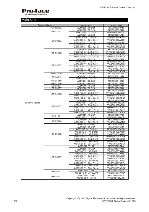
Main UnitModel No.Global Code AGP3200-A1-D24PFXGP3200AAD AGP3200-T1-D24PFXGP3200TAD AGP3200-T1-D24-M PFXGP3200TADC AGP3300-L1-D24PFXGP3300LAD AGP3300-L1-D24-M PFXGP3300LADC AGP3300-L1-D24-D81K PFXGP3300LADDK AGP3300-L1-D24-D81C PFXGP3300LADDC AGP3300-L1-D24-FN1M PFXGP3300LADFN AGP3300-L1-D24-CA1MPFXGP3300LADCA AGP3300-S1-D24PFXGP3300SAD AGP3300-S1-D24-D81K PFXGP3300SADDK AGP3300-S1-D24-D81C PFXGP3300SADDC AGP3300-S1-D24-CA1MPFXGP3300SADCA AGP3300-T1-D24PFXGP3300TAD AGP3300-T1-D24-M PFXGP3300TADC AGP3300-T1-D24-D81K PFXGP3300TADDK AGP3300-T1-D24-D81C PFXGP3300TADDC AGP3300-T1-D24-FN1M PFXGP3300TADFN AGP3300-T1-D24-CA1MPFXGP3300TADCA AGP3300-U1-D24PFXGP3300UAD AGP3301-L1-D24PFXGP3301LAD AGP3301-L1-D24-M PFXGP3301LADC AGP3301-S1-D24PFXGP3301SAD AGP3302-B1-D24PFXGP3302BAD AGP3310-T1-D24PFXGP3310TAD AGP3360-T1-D24PFXGP3360TAD AGP3400-S1-D24PFXGP3400SAD AGP3400-S1-D24-D81K PFXGP3400SADDK AGP3400-S1-D24-D81C PFXGP3400SADDC AGP3400-S1-D24-CA1MPFXGP3400SADCA AGP3400-T1-D24PFXGP3400TAD AGP3400-T1-D24-M PFXGP3400TADC AGP3400-T1-D24-D81K PFXGP3400TADDK AGP3400-T1-D24-D81C PFXGP3400TADDC AGP3400-T1-D24-FN1M PFXGP3400TADFN AGP3400-T1-D24-CA1MPFXGP3400TADCA AGP3450-T1-D24PFXGP3450TAD AGP3450-T1-D24-M PFXGP3450TADC AGP3500-L1-D24PFXGP3500LAD AGP3500-L1-D24-D81CPFXGP3500LADDC AGP3500-S1-AF PFXGP3500SAA AGP3500-S1-D24PFXGP3500SAD AGP3500-S1-D24-M PFXGP3500SADC AGP3500-S1-AF-D81K PFXGP3500SAADK AGP3500-S1-AF-D81C PFXGP3500SAADC AGP3500-S1-D24-D81K PFXGP3500SADDK AGP3500-S1-D24-D81C PFXGP3500SADDC AGP3500-S1-AF-CA1M PFXGP3500SAACA AGP3500-S1-D24-CA1MPFXGP3500SADCA AGP3500-T1-AF PFXGP3500TAA AGP3500-T1-D24PFXGP3500TAD AGP3500-T1-AF-D81K PFXGP3500TAADK AGP3500-T1-AF-D81C PFXGP3500TAADC AGP3500-T1-D24-D81K PFXGP3500TADDK AGP3500-T1-D24-D81C PFXGP3500TADDC AGP3500-T1-AF-FN1M PFXGP3500TAAFN AGP3500-T1-D24-FN1M PFXGP3500TADFN AGP3500-T1-AF-CA1M PFXGP3500TAACA AGP3500-T1-D24-CA1MPFXGP3500TADCA AGP3510-T1-AF PFXGP3510TAA AGP3510-T1-AF-CA1MPFXGP3510TAACA AGP3550-T1-AF PFXGP3550TAA AGP3550-T1-AF-MPFXGP3550TAACGP3000 SeriesGP-3310T GP-3360T GP-3500TGP-3400TGP-3510T GP-3550TGP-3301S GP-3200AGP-3300U GP-3302B GP-3301L Product NameGP-3450T GP-3500LGP-3500SGP-3200TGP-3300LGP-3300SGP-3300TGP-3400SModel No.Global Code AGP3560-T1-AF PFXGP3560TAA AGP3560-T1-AF-M PFXGP3560TAAC AGP3600-T1-AF PFXGP3600TAA AGP3600-T1-AF-M PFXGP3600TAAC AGP3600-T1-D24PFXGP3600TAD AGP3600-T1-D24-M PFXGP3600TADC AGP3600-T1-AF-D81K PFXGP3600TAADK AGP3600-T1-AF-D81C PFXGP3600TAADC AGP3600-T1-D24-D81K PFXGP3600TADDK AGP3600-T1-D24-D81C PFXGP3600TADDC AGP3600-T1-AF-FN1M PFXGP3600TAAFN AGP3600-T1-D24-FN1M PFXGP3600TADFN AGP3600-T1-AF-CA1M PFXGP3600TAACA AGP3600-T1-D24-CA1M PFXGP3600TADCA AGP3600-U1-D24-CA1MPFXGP3600UADCA AGP3650-T1-AF PFXGP3650TAA AGP3650-T1-AF-M PFXGP3650TAAC AGP3650-T1-D24-M PFXGP3650TADC AGP3650-U1-D24PFXGP3650UADC AGP3750-T1-AF PFXGP3750TAA AGP3750-T1-AF-M PFXGP3750TAAC AGP3750-T1-D24PFXGP3750TAD AGP3750-T1-D24-M PFXGP3750TADC AGP3300H-L1-D24PFXGP3300HLAD AGP3300H-S1-D24PFXGP3300HSAD AGP3310H-T1-D24PFXGP3310HTAD AST3201-A1-D24PFXST3201AAD AST3211-A1-D24PFXST3211AAD AST3301-B1-D24PFXST3301BAD AST3301-S1-D24PFXST3301SAD AST3301-T1-D24PFXST3301TAD AST3302-B1-D24PFXST3302BAD AST3401-T1-D24PFXST3401TAD AST3501-C1-AF PFXST3501CAA AST3501-C1-D24PFXST3501CAD AST3501-T1-AF PFXST3501TAA AST3501-T1-D24PFXST3501TADSoftware" ** " is changed with the version of software.Model No.Global CodeEX-EDV**PFXEXEDV**EXEDV**PFXEXEDV**EX-ED-LICENSE-V**PFXEXEDLSV**EX-SDV-V**PFXEXSDVV**EX-SED-LICENSEPFXEXSDLS EX-SRT-LICENSEPFXEXSRLS EX-MES-LICENSE-V**PFXEXMSLSV**EX-VIEWER-LICENSE PFXEXVW EX-VIEWER-LICENSE-10PFXEXVWLS10EX-VIEWER-LICENSE-30PFXEXVWLS30Camera Viewer EXEXCAVELS PFXEXCAVELS EX-RPA PFXEXRP EX-RPA-10PFXEXRPLS10EX-RPA-30PFXEXRPLS30EX-LADM-MIT-Q02PFXEXLMQ2LS EX-LADM-MIT-A01PFXEXLMA1LS EX-LADM-OMR-CJ01PFXEXLMCJ1LSEX-MOVCON-LICENSEPFXEXMCLS EX-WINGP-IPCPFXEXWGIP EX-WINGP-PCATPFXEXWGPC ST-3401T ST-3501C ST-3501TST-3301B GP-3650T GP-3650U GP-3750T GP-3300HL ST-3211A ST-3201A GP-3560T Product NameGP-3600TGP-3600TGP-3600U ST-3301S ST-3301T ST-3302B GP-3300HS GP-3310HT Product Name GP-Pro EX Editor License GP-Pro EX V*.*Pro-Server EX DeveloperPro-Server EX Developer License Pro-Server EX Runtime LicenseMES Action LicenseVideo Converter LicenseLadder Monitor License WinGP for IPC WinGP for PC/ATST3000 SeriesGP3000 SeriesSingle license10 licenses30 licensesRPA Client License GP-Viewer EX 10 licenses30 licenses Single license Single licenseExpansion UnitModel No.Global Code CA5-PFSALL/EX-01PFXZC5EUPFS CA6-DNSALL/EX-01PFXZC6EUDNS1CA9-CANALL/EX-01PFXZC9EUCA1CA7-CCLALL/EX-01PFXZC7EUCL1GP3000-VM01PFXZGPEUVM31GP2000-VM41PFXZGPEUVM21GP3000-DVI01PFXZGPEUDV01GP3000-RGB201PFXZGPEURG215m FP-DV01-50PFXZC0CBDV5110mFP-DV01-100PFXZC0CBDV1015m CA7-CBLCVRGB-01PFXZC7CBCVRG515mCA9-USBAMB/5M-01PFXZC9CBUSMB514.5m FP-CV02-45PFXZC0CBRG451CA9-USBATRGB/MB-01PFXZC9CLUSATRG1Model No.Global Code FN-XY32SKS41PFXZFNXY32K FN-X32TS41PFXZFNX32TS FN-XY16SK41PFXZFNXY16K FN-XY16SC41PFXZFNXY16C FN-Y08RL41- *FN-AD02AH41PFXZFNAD2FN-DA02AH41PFXZFNDA2FN-AD04AH11PFXZFNAD4FN-DA04AH11PFXZFNDA410m FN-CABLE2010-31-MS - *50mFN-CABLE2050-31-MS PFXZCBFN50200mFN-CABLE2200-31-MSPFXZCBFN200*There's no global code added for the products whose last order had been completed by December 31, 2011.Model No.Global Code HTB1C0DM9LP PFXHTB1C0DM9LP EXM-DDI8DT PFXZLTEUDDI8DT EXM-DDI16DT PFXZLTEUDDI16DT EXM-DRA8RT PFXZLTEUDRA8RT EXM-DRA16RT PFXZLTEUDRA16RT EXM-DDO8UT PFXZLTEUDDO8UT EXM-DDO16UK PFXZLTEUDDO16UK EXM-DDO8TT PFXZLTEUDDO8TT EXM-DDO16TK PFXZLTEUDDO16TK EXM-DMM8DRT PFXZLTEUDMM8DRT EXM-DMM24DRF PFXZLTEUDMM24DRF EXM-AMI2HT PFXZLTEUAMI2HT EXM-ALM3LT PFXZLTEUALM3LT EXM-AMM3HT PFXZLTEUAMM3HT EXM-AMO1HT PFXZLTEUAMO1HT EXM-AMI4LT PFXZLTEUAMI4LT EXM-AVO2HT PFXZLTEUAVO2HT EXM-AMM6HT PFXZLTEUAMM6HT EXM-ARI8LTPFXZLTEUARI8LTDVI-I/RGB Conversion Cable USB Cable for RGB Input Unit Analog RGB Cable USB Cable anti-disconnect holder (RGB Input Unit Side-miniB)4-ch Analog Input/ 2-ch Analog OutputModule8-ch Thermocouple Pt100/ Pt1000 InputModuleProduct Name2-channel Analog/Digital Conversion Unit 2-channel Digital/Analog Conversion Unit 4-channel Analog/Digital Conversion Unit VM Unit DVI Input Unit RGB Input UnitDVI-D CableCC-Link UnitProduct Name CANopen Slave UnitPROFIBUS Slave Unit DeviceNet Slave Unit 2-ch Analog Output Module32-point Input Sink/Source and 32-pointTransistor Output Sink Type 32-point Input Sink / Source Type 16-point Input Sink/Source and 16-pointTransistor Output Sink Type16-point Input Sink/Source and 16-pointTransistor Output Source type4-channel Digital/Analog Conversion UnitFLEX NETWORKCommunication Cable8-point Relay 0utput and 1 Common Type 4-ch Analog Input/ Thermocouple InputModuleCANopen Slave HTB Unit 8-Point Input Module 8-Point Relay Output Module 8-Point Sink Output Module 8-Point Source Output Module 2-ch Analog Input / 1-ch Analog OutputModule16-Point Sink Output Module 16-Point Source Output Module16-Point Input/ 8-point Relay Output Module 4-Point Input / 4-Point Relay Output Module 2-ch Thermocouple Pt100 Input / 1-ch AnalogOutput Module1-ch Analog Output Module16-Point Input Module 16-Point Relay Output Module 2-ch Analog Input ModuleProduct NameOptionsModel No.Global Code 5m CA3-CBL232/5M-01PFXZC3CBR2515m CA3-CBL422-01PFXZC3CBR4525m CA3-CBL422/5M-01PFXZC3CBR4515m CA3-CBLA-01PFXZC3CBA515m CA3-CBLQ-01PFXZC3CBQ515m CA3-CBLLNKMQ-01PFXZC3CBQL515m CA3-CBLFX/5M-01PFXZC3CBFX511m CA3-CBLFX/1M-01PFXZC3CBFX115m CA3-CBLSYS-01PFXZC3CBSYS515m CA6-CBLTTY/5M-01PFXZC6CBTTY51ST03-A2B-MPI21-PFE PFXZGPCBMPPE1GP3000-MPI21-PFE PFXZGPCBMPPE4CA3-MPIPG1-PFE PFXZGPCBMPPE5CA3-MPIPGN-PFE PFXZGPCBMPPE65mCA3-CBLMLT-01PFXZC3CBML120cmCA3-CBLCBT232-01PFXZC3CBCVR2120cmCA3-CBLCBT422-01PFXZC3CBCVR41GP070-MD11PFXZGPADMD15m CA3-MDCB11PFXZC3CBMD1CA3-ADPCOM-01PFXZC3ADCM1CA4-ADPONL-01PFXZC4ADCM1CA3-ADPTRM-01PFXZC3ADR41CA3-ADPSEI-01PFXZC3ADSE1CA3-ISO232-01PFXZC3ADISR21CA3-ISO485-01PFXZC3ADISR812mCA3-USBCB-01PFXZC3CBUSA15m FP-US00PFXZC0CBUS11mCA5-USBEXT-01PFXZC5CBUBEX150cmCA6-USB232-01PFXZC6CBCVUSR21RS-232C 9-pin/25-pin ConversionCableRS-485 Isolation Unit Siemens TTY Converter CableMitsubishi PLC Q Series Link Cable RS-422 Cable (Socket Type)Mitsubishi PLC A-SeriesConnection Cable Mitsubishi PLC Q-SeriesConnection Cable 3.5mProduct NameRS-232C CableRS-232C Isolation Unit RS-422C 9-pin/25-pin ConversionCable2-port Adapter II Cable 2-port Adapter IICOM Port Conversion AdapterOnline AdapterUSB Transfer Cable Multi-Link Cable Omron PLC SYSMAC Link Cable Terminal Block Conversion Adapter Siemens COM Port Conversion AdapterRS-422 Cable (Plug Type)MPI CableUSB cable USB Front Cable USB-Serial (RS-232C) ConversionCableMitsubishi PLC FX-SeriesConnection CableModel No.Global Code AGP3000H-ADPCOM-01PFXZGPADCM3H13m GP3000H-CBLS-3M PFXZGPCBS315m GP3000H-CBLS-5M PFXZGPCBS5110m GP3000H-CBLS-10M PFXZGPCBS10110m GP3000H-CBLH-10M PFXZGPCBH1013m GP3000H-CBLSD-3M PFXZGPCBSD315m GP3000H-CBLSD-5M PFXZGPCBSD5110m GP3000H-CBLSD-10M PFXZGPCBSD10110mGP3000H-CBLHD-10M PFXZGPCBHD101GP2000H-AP232PFXZGPADR22H GP2000H-AP422PFXZGPADR42H 3m GP3000H-CBLSD232-3M PFXZGPCBSDR231110m GP3000H-CBLSD232-10M PFXZGPCBSDR21013m GP3000H-CBLSD422-3M PFXZGPCBSDR43110mGP3000H-CBLSD422-10M PFXZGPCBSDR4101GP3000H-WMA-01PFXZGPADWMA1GP2000H-STRAP11PFXZGPST2H2128MB CA3-CFCALL/128MB-01PFXZC3CF1281256MB CA3-CFCALL/256MB-01PFXZC3CF2561512MB CA3-CFCALL/512MB-01PFXZC3CF51211GB CA6-CFCALL/1GB-01PFXZC6CF112GB CA8-CFCALL/2GB-01PFXZC8CF21GP077-CFAD10PFXZC0ADCF1GP3000-EXDM01PFXZGPIUEXDM CA6-DFS4-01PFXZC6DS41GP3000H-DFS6-01PFXZGPDS3H61CA3-DFS6-01PFXZC3DS61PS400-DF00PFXZGPDS71CA5-DFS10-01PFXZC5DS101CA3-DFS12-01PFXZC3DS121CA3-DFS15-01PFXZC3DS151CA4-DCMDL-01PFXZC4CNDCM1CA8-ODP10-01PFXZC8OP101GP077-SDAD10PFXZC0ADSJ1CA7-TPPEN/ALL-01PFXZC7TPP1CA4-ATM5-01PFXZC4AT61CA4-ATM10-01PFXZC4AT101for 3.8 inch for GP3000H CF CardNeck Strap GP3000H Soft-type Cable (RS-422) for GP2000H Conversion Adapter (with connector)GP3000H Soft-type Cable (RS-232C) for GP2000H ConversionAdapter (with connector)CF Card AdapterFunction Expansion MemoryPin Jack AdapterTouch Penfor 10.4 inch (TFT)GP2000H Series RS-422 Conversion Adapter Wall Hanging AdapterGP2000H Series RS-232C Conversion Adapter for 15 inch Screen ProtectionSheetfor 5.7 inch for 10.4 inch (TFT)for 5.7 inch for 7.5 inch GP3000H Soft-type Direct-connectCable (with connector)GP3000H Hard-type 10 m Direct-connect Cable (with connector)GP3000H Conversion AdapterGP3000H Soft-type Direct-connectCable GP3000H Hard-type 10m Direct-connect Cable for 12.1 inch/10.4inch(STN)for 5.7 inchfor 10.4 inch (TFT)Panel Cutout AdapterEnvironmentally-resistant CoverProduct NamePlease purchase when the products is damaged or lost.Model No.Global CodeCA6-FNCNALL-01PFXZC6CNFN1GLC-DIOCN03PFXZFNCNXY641CA7-HTBCNSET-01PFXZC7CNHTB1CA6-EXMCNHE20P-01PFXZC6CNEXHE201CA6-EXMCNRS11P-01PFXZC6CNEXRS111CA6-EXMCNRS10P-01PFXZC6CNEXRS101CA5-USBATM-01PFXZC5CLUSBM CA8-USBATALL-01PFXZC8CLUSB1CA5-USBATL-01PFXZC5CLUSBL GP3000H-DUPS-01PFXZGPDUPS1GP3000H-HS-01PFXZGPHS1GP3000H-EMGD-01PFXZGPEMGD1GP3000H-WPGADP-01PFXZGPWGHAD1CA5-BLU10T-01PFXZC5BL101CA6-BLU10T-02PFXZC6BL101PS501S-BU00PFXZGPBL102CA3-BLU12-01PFXZC3BL121CA3-BLU15-01PFXZC3BL151ST400-WP01PFXZSTWG41CA3-WPG6-01PFXZC3WG61CA5-WPG8-01PFXZC5WG81CA5-WPG10-01PFXZC5WG101CA3-WPG12-01PFXZC3WG121CA3-WPG15-01PFXZC3WG151CA3-ATFALL-01PFXZC3AT1CA3-BUSCVR-01PFXZC3CVBUS1CA5-DCCNM-01PFXZC5CNDCM1CA5-DCCNL-01PFXZC5CNDCL1CA5-AUXCNALL-01PFXZC5CNAX1CA6-DIOCNALL-01PFXZC6CNXY81Product NameAUX Connector DIO ConnectorUSB Cable Clamp (1 port) USB Cable Clamp (1 port) USB Cable Clamp (2 ports) Installation Gasket Function Switch SheetHand StrapEmergency Stop Switch Guard64-point DIO Connector Terminal Connector (10 pin) for EX moduleDIO Connector for HTBMIL Connector (20 pin) for EX module Terminal Connector (11 pin) for EX module FLEX NETWORK Connector for 7.5 inch for 10.4 inch (TFT)for 12.1 inch /10.4 inch(STN)for 10.4 inch(TFT)for 12.1 inch for 15 inch for 3.8 inch for 10.4 inch or largerDC Power SupplyConnectorfor 15 inchInstallation GasketInstallation Fastener Bus Connector CoverReplacement Backlightfor 7.5 inch/5.7 inch/3.8 inchfor 5.7 inch。
《ALCOR量产工具操作手册》
ALCOR量产工具操作手册2012.11.22目录1.运行环境 (1)2.主要功能 (1)2.1FLASH支持部分 (1)2.2U盘制作功能 (1)3.快速使用方法 (2)4.设定界面详细说明 (3)4.1主界面 (3)4.2密码设定 (4)4.3存储器设定 (5)4.3.1存储器类别 (5)4.3.2鼠产设定 (5)4.4装置方式设定 (8)4.4.1普通盘 (8)4.4.2本地盘 (9)4.4.3只读盘 (9)4.4.4加密盘 (10)4.4.5AES 盘 (10)4.4.6AutoRun 盘 (10)4.5 U盘信息设定 (12)4.6坏磁区设定 (13)4.7其它设定 (15)4.8界而显示 (16)4.9导出配置和导入配置 (17)5.MP错误代码对照表 (18)6.常见错误详解 (21)1.运行环境适用J - Wmdows XP, Wui7,Win8。
该软件是绿色版的,不用安装即可以使用。
2.主要功能2.1 FLASH支持部分1)最多可以16个U盘同时虽产。
2)支持不同型号的FLASH同时吊产,并可单独停止或开始任意一颗的吊:产。
3)自动识别FLASH型号、ID、CE数目,也可手动选择FLASH型号进行昂产。
4)支持单贴、双贴、单通道和双通道。
5)''低格检测、'设定,可■支持Half Page及其它特殊状况的FLASH,6)提供手动选择ECC设定。
7)有高级格式化和低级格式化两种扫描方式:a.高级格式化指扫描时直接读取FLASH的坏块信息,分为全新、全新+AA55、量产过和清空四个扫描级别:全新:直接读取原厂坏块信息。
全新+AA55:全新扫描+简单的检测。
量产过:直接读取上一次量产写入的坏块信息(必须是该量产I.具呐产过)。
清空:将FLASH存储的信息全部清空。
b.低级格式化指扫描时写数据到FLASH再读出来比较以确定坏块,扫描级别分两大类:全面扫描:对FLASH的所有位置进行检测。
MOXA NE-4100系列网络启用器产品介绍说明书

P/N: 1802041000302*1802041000302*NE-4100 Series Quick Installation GuideVersion 5.1, December 2019Technical Support Contact Information /support Moxa Americas:Toll-free: 1-888-669-2872Tel: 1-714-528-6777Fax: 1-714-528-6778 Moxa China (Shanghai office): Toll-free: 800-820-5036 Tel: +86-21-5258-9955 Fax: +86-21-5258-5505 Moxa Europe:Tel: +49-89-3 70 03 99-0Fax: +49-89-3 70 03 99-99 Moxa Asia-Pacific: Tel: +886-2-8919-1230 Fax: +886-2-8919-1231 Moxa India:Tel: +91-80-4172-9088Fax: +91-80-4132-10452019 Moxa Inc. All rights reserved.OverviewThe MOXA NE-4100 Series of Network Enablers are serial-to-Ethernet embedded modules that come in 3 types: drop-in type (NE-4100T), RJ45 type (NE-4110S/A), and pin-header type (NE-4120S/A). MOXA provides a Starter Kit for each NE-4100 series module. Each Starter Kit contains an evaluation board that can be used to evaluate the modules and to develop applications. The following table lists the model names of all NE-4100 Series modules, along with the model names of the corresponding Starter Kits.Starter Kit Model NamesNE-4100 Series Model Names Standard ProgrammableNE-4100-ST NE-4100T NE-4100T-PNE-4110-ST NE-4110S NE-4110S-P NE-4110A NE-4110A-PNE-4120-ST NE-4120S NE-4120S-P NE-4120A NE-4120A-PPackage ChecklistEach NE-4100 series starter kit package contains the following items: • 1 NE-4100 series evaluation board• 1 universal power adaptor• 2 power cords• 1 null modem serial cable• 1 cross-over Ethernet cable• 1 quick installation guide (printed)• 1 warranty cardNotify your sales representative if any of the above items is missing or damaged.Hardware Installation ProcedureFollow these steps to prepare the module and evaluation board for testing and application development.STEP 1: Plug the NE-4100 module into the sockets on the top of the evaluation board.NE-4100-ST:After attaching the module to the evaluation board, the triangles on the module and evaluation board should line up.NE-4100-ST Starter KitNE-4110-ST:The module and evaluation board have two jumper arrays, each with a pin labeled 1. Be sure to connect the correct Pin 1 on the module to the correct Pin 1 on the evaluation board.NE-4110-ST Starter KitNE-4120-ST:The module and evaluation board have two jumper arrays, each with a pin labeled 1. Be sure to connect the correct Pin 1 on the module to the correct Pin 1 on the evaluation board.NE-4120-ST Starter KitNOTE For detailed information about the pin assignments, wiring, LED indicators, and board layouts, refer to Chapter 2 of the NE-4100 Series User’s Manual.STEP 2: Connect the 12 VDC power line with the evaluation board’s power jack.STEP 3: Use an RJ45 Ethernet cable to connect the NE evaluation board plus module to an Ethernet network. Note that for NE-4100T and NE-4120, the RJ45 Ethernet port is located on theevaluation board. For NE-4110, the RJ45 Ethernet port islocated on the module itself.STEP 4: Use the serial data cable to connect the evaluation board to a serial device.STEP 5: For NE-4110-ST and NE-4120-ST, use jumper JP2 on the evaluation board to select the proper serial interface. Seepages 3-6 and 3-7 of the NE-4100 Series User’s Manual fordetails.Software Utility Installation ProcedureNE-4100 ModuleSoftware Installation1.Start the “Network Enabler Administrator” setup program to beginthe installation. When the Welcome window opens, click on Next.2.When the Select Additional Tasks window opens, click on Next.3.Click on Install to install program files in the default directory.4.The Installing window reports the progress of the installation.5.Click on Finish to complete the installation.Module Configuration1.Start the “Network Enabler Administrator” program.2.Click on Configuration from the menu bar, and then selectBroadcast Search from the drop-down menu.3.After the search is finished, all NE-4100 modules that were foundwill be shown in the right panel of the Configuration window. Ifyou locate more than one module connected to this network, refer to the MAC address on the module(s) to determine which modules are the ones you wish to configure.4.Refer to pages 7-6 to 7-19 of the NE-4100 Series User’s Manualfor additional configuration instructions.NE-4100 Programmable ModuleSoftware Installation1.Start the “Network Enabler SDK” setup program to begin theinstallation. When the Welcome window opens, click on Next. 2.Select the target directory, and then click on Next when theSelect Destination Directory window opens.3.Click on Next when the Select Additional Tasks window opens.4.Click on Install. The Installing window will report the progress ofthe installation.5.Click on Finish to complete the installation.Module Configuration1.Start the “NE SDK Manager” program.2.Click on Search from the menu bar, and then select BroadcastSearch from the drop-down menu.3.After the search is finished, all NE-4100-P modules that werefound will be shown in the NE SDK Manager window. Refer to the “Network Enabler SDK 2 Programmer’s Guide” for additionalinformation about setting environment variables and developingapplications with NE-4100-P Series products.Reference MaterialThe following detailed user’s guides can be downloaded from Moxa’s product page under the NE-4100 Series’ product page.NE-4100 Standard Module•NE-4100 Series User’s ManualNE-4100-P Series•Network Enabler SDK 2 Programmer’s Guide•Network Enabler SDK 2 API Reference。
USBOS_V3.0校验值及更新说明

【2016-04-20】
01、精简X86 8PE中WMIC组件里查询CPU、安装的RAM所需文件之外的其余文件。
02、0.46a版GRLDR一律升级为20160413版(在新机使用GRLDR内置的USB驱动加速时,其副作用大为减少,此外新GRLDR修正了硬盘存在EXT2/4分区时,03PE启动不了的BUG)。
文件: USBOS_V3.0.zip.002
大小: 205, 520, 896 字节
MD5: 8660F1E43E3EA4040C9C0FC8A9D90BB6
文件: USBOS_V3.0.zip.003
大小: 205, 520, 896 字节
MD5: FFF7614D67259837D192D1C0BD24EE5B
1、升级DISM++为10.1.6.5;
2、升级Intel Nvme(X86&X64)驱动为1.5、Apple BootCamp(X64)为6.0.6427;
【2016-09-08】
1、升级DISM++为10.1.9.1、DISM为10.0.14393.0、WinntSetup为3.8.7 B4;
【2016-11-29】
维护版8.1 RAMOS升级为Windows 10PE,总版本号升级为3.0。
1、Windows 10 原生驱动包相当强悍,常见SRS均不需再额外集成。Nvme驱动按理也无需集成。
追加了几款OEM驱动(均未声明是为NT10设计、使用效果未知),主要有Apple的一些键盘鼠标触摸板及SSD及个别DELL HP的阵列卡。
EZ3600用户操作手册说明书

直到小户户户出户声,户示
PROGRM ,第一个已户户程户的日粮就会户
示,如果从没有户程户,户户示 rec__
2. 重户按
直到屏幕户示需要户除的日粮配
方的户号
5 3. 按住
直到户示 press zero to delete
recipe – press net/gross to quit
4. 按
以清除日粮配方
2. 重户按 号
直到户示所要户行修改的日粮户
3. 按
户定要修改此户号户户的日粮配方
4
corn
6/8
4. 首先户示第一个户分的名称,户接着是 AMOUNT 及此后户户数量
5. 户入新的数量
6. 按
以保存修改后的数量,户户修改其他
户分及数量
9 7. 重户上述第 5 和 6 户修改配方中的其他户分
的数量
5
3. 按
2
确定户户户 程日粮的模式
户程日粮配方
Rec_
3 1
4 2
1. 按住
直到小户户户出户声,户示
PROGRM ,第一个已户户程户的日粮就会户
示,如果从没有户程户,户户示 rec__
2. 按
或者,
3. 户入需要的日粮配方户号
4. 按
确定户入户户的日粮配方户号
5. 使用向上 称
和向下 户户各户分的名
EZ3600V 用户操作手册
可户程称重小户户
HELLO
D3832-CN Rev D
Ft. Atkinson, 威斯康辛 美国
Panningen, 荷户
2011-5-30
著作户声明
版户所有。未户 Digi-Star 户面户可,户禁户制、户户或抄户户手册中的一切内容。我户将户户手册内容不定期户行更新和修正,恕不另行通知。户户反户校 户核准,因户户所限,本手册不免有疏漏户户之户,Digi-Star 感户您通知我户户些户户。尽管如此,我们对因此造成的损失不承担任何责任。 © 版户所有! 2008 Digi-Star, Fort Atkinson (美国).
Statox 505 传感头操作手册说明书
Statox 505 Sensor HeadOperations ManualStatox 505 Sensor HeadOperations Manual1SAFETY INSTRUCTIONS 32STATOX 505 CONSTRUCTION 43INSTALLATION AND CONNECTION 5 3.1Warning 5 3.2Installation 5 3.3Electrical connection 63.3.1Statox 505 cable connection 73.3.2Connection diagram with Statox 501 Control Module in the 2-wire mode 83.3.3Connection diagram with Statox 501 Control Module in the 3-wire mode 103.3.4Connection diagram with Statox 502/503 Control Module in the 2-wire mode 123.3.5Connection diagram with Statox 502/503 Control Module in the 3-wire mode 134START –UP AND SERVICE 14 4.1Start - up and measuring mode 15 4.2Setting the realtime clock 16 4.3Setting the “service mode“ ou tput signal 17 4.4Calibrating the sensor 18 4.5Prooftest 20 4.6Info menu 21 4.7Test menu 225SENSOR REPLACEMENT 236MAINTENANCE 247SPARE PARTS AND ACCESSORIES 248STATUS- AND ERROR MESSAGES 25 8.1Status messages 25 8.2Error messages 26 9TECHNICAL DATA 27 9.1General transmitter data 27 9.2Sensor specific data 28 10CE-DECLARATION OF CONFORMITY 2921 Safety InstructionsThe Statox 505 sensor head is certified as explosion-proof safety equipment for group II category 2.The intended use is the measurement of toxic gas and oxygen concentration. Due to its intrinsically safe design it is safe to install and operate this product in zone 1 and zone 2.All relevant sensor parameters will be set automatically as soon as the sensor is connected.The following safety guidelines must be observed in particular:∙When installing and connecting the transmitter, the safety relevant electrical parameters and the protection class of the sensor head must comply with local standards (e.g. IEC 60079-14).∙If installed in a hazardous area, the power supply of the sensor heads must be intrinsically safe.Recommended products see connection diagrams in chapter 3.3 and in chapter 7 (accessories).∙The sensor head may only be operated within the specified environmental conditions.∙Damaged or not tightly closed housings may cause malfunction or loss of accuracy.All of the above warnings must be observed. Incorrect installation or connection will void the explosion proof rating and thus be dangerous to life and assets.34 2 Statox 505 constructionThe housing cover is attached with 4 bayonet screws. To open it, just turn these screws 90° counter - clockwise. The cover is secured to the housing with a steel strap.1 Mounting plate with 4 holes φ 10 mm2 Push buttons3 Display4 LED5 Programming interface (not for customer use)6 Cable terminal X17 Ground terminal8 Clamp for cable shield 9 cable gland M16x1,510 Sensor cover including filter support 11Securing strap for sensor cover167113 Installation and connection3.1 WarningIf the sensor head is installed in hazardous areas, the power supply must be intrinsically safe. Observe the safety - relevant specifications of sensor head, cable and barrier respectively intrinsically safe repeater.Caution:Do not install the sensor unless the sensor head has been connected to the power supply.The following specifications must be observed:U o, I o, C o, L o :certified repeater specificationsU i, I i, C i, L i : sensor head specifications (→ technical data)C L = cable capacity in pF/mL L = cable inductivity in nH/ml = cable length in mThe allowable cable length is defined in most cases by the cable capacity:l max = C o / C L (C i is negligible).Recommended cable type: see chapter 3.3.3.2 InstallationInstall the sensor head sensor downwards. Use stainless steel screws or insulate screws from mounting plate to avoid corrosion. In case of potential static voltage, ground the sensor head.The sensor head can be mounted to a wall with2 or 4 screws without opening the housing:Alternatively it can be mounted to a horizontalor vertical pipe. Statox 505 pipe mounting kitsare listed in chapter 7 accessories.5Statox 505 drilling plan and dimensions3.3 Electrical connection∙Use cable with 2 or 3 x ≥ 0,75 mm² with close - mashed shield, outer diameter ca. 6 mm(e.g. type Oelflex 415 CP3 X 0,75).∙Advantage of 3 - wire operation:In the two wire mode, the output signal for service and system failure is the same (2 mA).In the 3 - wire mode you can differentiate between “service” (non - critical = 2 mA) and “failure”(critical = 0 mA).∙If connecting the Statox 505 sensor head to a Statox 501 control module, follow the connecting diagrams in the chapters 3.3.2 and 3.3.3.If connecting the Statox 505 sensor head to a Statox 502/503 control module, follow the connecting diagrams in the chapters 3.3.4 and 3.3.5.If connecting the Statox 505 sensor head directly to a PCS, observe the following connecting diagram.In case of 2-wire-mode use only terminals 1 and 2.Statox 505 PCS63.3.1 Statox 505 cable connection∙Use cable with 2 or 3 x ≥ 0,75 mm² with close – mashed shield, outer diameter ca. 6 mm(e.g. type Oelflex 415 CP3 X 0,75).∙Do not install the sensor unless the sensor head is connected to the power supply.∙Run 20 cm (8 in) of cable through the cable gland.∙Strip the cable down to the shield. (A)∙Shorten the shield to 10 mm (0,4 in) and bend it backward. Make sure it does not touch the housing. (B)∙Connect the wires as shown in the schematics. The terminal is plugged in. Remove it for easy installation.∙Draw the cable back until the shield matches the clamp∙Fasten the cable gland.∙Secure the shield with the clamp. Good contact provides best protection from electromagnetic interference.∙Plug the terminal in.∙When the sensor head is connected to the power supply, the LED starts flashing for a short time and the display shows the software index.∙Now install the sensor (see chapter 4).A B C123Ø 5 - 7 mmX173.3.2 Connection diagram with Statox 501 Control Module in the 2-wire modeBefore connecting the sensor head, select the appropriate program. Refer to the Statox 501 operations manual and the program overview.3.3.2.1 2-wire mode installation in non hazardous areas83.3.2.2 2-wire mode installation in hazardous areasCaution: Incorrect connection of the intrinsically safe repeater might destroy it. Please take care for correct polarity and avoid short circuits.Repeater forms a current source: the terminal numbers on the drawing below refer to repeater type 9160/13-11-11s from manufacturer R.Stahl Schaltgeräte GmbH (or Siemens type 7NG4124-0AA00).It requires an extra power supply and forms a current source at clamps 1 and 2.A1 A2 SF 4-20mA A1 A2 Horn SFRepeater forms a current sink: the terminal numbers on the drawing below refer to repeater type9160/13-10-11s from manufacturer R.Stahl Schaltgeräte GmbH. It requires an extra power supply and forms a current sink at clamps 1 and 2.A1 A2 SF 4-20mA A1 A2 Horn SF93.3.3 Connection diagram with Statox 501 Control Module in the 3-wire modeBefore connecting the sensor head select the appropriate program. Refer to the Statox 501 operations manual and the program overview.3.3.3.1 3-wire mode installation in non – hazardous areasA1 A2 SF 4-20mA A1 A2 Horn SF103.3.3.2 3-wire mode installation in hazardous areasCaution: Incorrect connection of the intrinsically safe repeater might destroy it. Please take care for correct polarity and avoid short circuits.Repeater forms a current source: the terminal numbers on the drawing below refer to repeater type 9160/13-11-11s from manufacturer R.Stahl Schaltgeräte GmbH (or Siemens type 7NG4124-0AA00). It requires an extra power supply and forms a current source at clamps 1 and 2.Repeater forms a current sink: the terminal numbers on the drawing below refer to repeater type 9160/13-10-11s from manufacturer R.Stahl Schaltgeräte GmbH. It requires an extra power supply and forms a current sink at clamps 1 and 2.operations manual and the program overview.3.3.4.1 2-wire mode installation in non-hazardous areas3.3.4.2 2-wire mode installation in hazardous areasCaution : Incorrect connection of the intrinsically safe repeater might destroy it. Please take care for correct polarity and avoid short circuits. The terminal numbers on the drawing refer to repeater type 9160/13-11-11s from manufacturer R.Stahl Schaltgeräte GmbH (or Siemens type 7NG4124-0AA00). It requires an extra power supply and forms a current source at clamps 1 and 2. Plant = hazardous area Non hazardous area Power supply X1 Power supply X1 RepeaterStatox 502/503 Statox 502/503operations manual and the program overview.3.3.5.1 3-wire mode installation in non-hazardous areas3.3.5.2 3-wire mode installation in hazardous areasCaution : Incorrect connection of the intrinsically safe repeater might destroy it. Please take care for correct polarity and avoid short circuits.The terminal numbers on the drawing refer to repeater type 9160/13-11-11s from manufacturer R.Stahl Schaltgeräte GmbH (or Siemens type 7NG4124-0AA00). It requires an extra power supply and forms a current source at clamps 1 and 2. Plant = hazardous area Non hazardous area Power supply X1 Power supply Repeater X1 Statox 502/503 Statox 502/5034 Start –up and serviceSensor head keyboard:Press UP and DOWN at the same time to enter the menu.Increase / decrease the displayed parameter.Press and hold button for fast forward.RESET: One level up in the menu.ENTERTimeout: The sensor head returns automatically into the measuring mode if no key is pressed for more than 5 minutes.4.1 Start - up and measuring mode∙As soon as the sensor head is connected to the power supply, it starts a self test and shows the software index.∙Now install the sensor and filter. Please observe the handling instructions in chapter 5 !∙Remove the yellow protection cap from the sensor cover!∙As soon as the sensor is connected, the sensor head displays the parameter version, the gas to be detected, the measuring range and the best before date of the sensor. As soon as zero has stabilized, the instrument goes into the measuring mode. The green LED starts flashing.As long as the sensor head is not ready, the output signal is in the system fail mode, i. e. 2 mA when operated in the 2 wire mode, 0 mA when operated in the 3 wire mode.∙When the sensor head has completed the start – up sequence, you can start setting the real time clock (see chapter 4.2) and the service mode output signal (see chapter 4.3).4.2 Setting the realtime clock∙The clock is set ex works to CET. Please set it to your local time to make sure you get correct protocols of calibration and alarms.∙The clock has a back-up battery to save the time setting when power is disconnected.∙The segments flashing can be set with the up / down buttons.∙You can leave the time set menu by pushing the reset button.4.3 Setting the “service mode“ output signal∙The following table shows the potential modes and outputs.Notice: During the sensor replacement in the REPLACE menu, the sensor head remains in the service mode - even if no sensor is connected!∙If the sensor head is operated as a safety relevant device according to EN 50402 (Functional Safety) the output in the service mode must be 2 mA !4.4 Calibrating the sensor∙ Sensor head and sensor must have the same temperature!∙ You need a Statox 505 calibration adapter (art.no. 570505), a gas tubing 4x1 mm (art.no. 556710) and span gas (acceptable gas concentrations see chapter 9.2). If the environment is not clean, you need synthetic air for zeroing.∙ In case the calibration fails for whatever reason, the sensor head will continue to operate with the existing parameters, but the display will alternate showing the measured value and ZERO ADJ or CALIB until a calibration procedure has been completed.∙ O 2-sensors do not require a zero adjustment, as their output in pure nitrogen is nearly 0 nA. The span calibration can be done with clean ambient air or synthetic air.Procedure∙ Affix the adapter on the sensor cover until it catches (clockwise rotation). ∙ Connect the calibration adapter to the span gas cylinder.∙ Enter the service menu and select code 11 to enter the calibration routine. Set Zero.∙ Push ENTER button. As soon as the display shows GAS ON, open the valve. The gas flow should be ca. 20 l/h (300 ml/min). If you want to avoid span gas to be released into the environment, you can connect an active carbon filter art.no. 806488 to the exhaust of the gas adapter. Make sure there is no pressure building up in the adapter!∙ The display will show GAS.IS.ON until the reading is stable. Then it will show CONCENT? Now press ENTER . The display will now show the concentration of the recently used span gas. If you have used a gas with different concentration, adjust with the up / down buttons and confirm with ENTER .∙ When the display shows DONE , press ENTER to display the present concentration. Now close the regulator and remove the calibration adapter (clockwise rotation).∙ To return to the measuring mode, press ENTER again. The green LED starts flashing. If you fail to press ENTER , the sensor head will return to the measuring mode automatically after a timeout of 5 minutes. Calibration adapter4.5 Prooftest∙ A prooftest provides a verification of the transmitter performance under field conditions. It must be performed in regular intervals, if the transmitter is used as a safety relevant device. As long as the menu “Prooftest” is active, the output signal is set to 2 or 4 mA. In case the entire alarm chain must be tested, this must be done in the measuring mode.∙You need the Statox 505 calibration adapter art.no. 570505, a gas tubing 4x1 mm , art.no. 556710 and span gas with a concentration within the measuring range, preferably close to the alarm threshold.∙Affix the adapter on the sensor cover until it catches (clockwise rotation).∙Connect the gas adapter to the span gas cylinder.∙Enter the service menu and choose code 99 to enter the proof test routine.∙As soon as the display shows PROOF, open the valve and press ENTER. The gas flow should be ca.20 l/h (300 ml/min). If you want to avoid span gas to be released into the environment, you canconnect an active carbon filter art.no. 806488 to the exhaust of the gas adapter. Make sure there is no pressure building up in the adapter!∙The display will show the present concentration. Wait until the signal is stable before reading.∙Close the gas regulator and remove the calibration adapter (clockwise rotation).∙Return to the measuring mode by pushing the RESET button, stepping upward in the menu until you reach the measuring mode.∙If a new calibration is necessary proceed according chapter 4.4.∙Special timeout: If you do not push a button for 30 minutes, the transmitter returns automatically to the measuring mode.∙ A 2- or 3-time LED flashing during the proof test signalizes a periodical hardware test.∙This menu provides information about alarm history and sensor parameters.∙The exposure recording starts as soon as the end of the measuring range is exceeded.You can access the most recent 3 alarm events (start, end of range and end). The alarm events are not listed chronologically. For oxygen sensors only: the exposure recording starts as soon as the measured value drops below the detectable limit (see chapter 9.2).∙The total exposure information (DOSIS) is not updated permanently. Exposure by calibration is neglected. The maximum exposure reading depends on the measuring range. It is either 9,99 or 99,9 or 999 ppm * min.∙The total exposure recording is inactive for oxygen sensors.∙The calibration factor is a parameter used by the microprocessor. It cannot be used to obtain information about the sensor signal.∙In order to check the signal loop, the sensor head can generate 4, 12 and 20 mA.Caution: this might trigger an external alarm!∙The display can be tested by displaying a sequence of fonts and patterns.∙The sensor head can also display temperature.5 Sensor replacementPlease observe the precautions to avoid electrostatic voltage, when handling electronic devices. To avoid the sensor from being removed, while exchanging data with the sensor head, enter the service menu before you remove it. In the menu REPLACE the sensor can be replaced without generating a system failure alarm (see chapter 4.3). During the sensor replacement the sensor head will remain in the service mode.Handling instructions:still remaining in the service mode. After pushing theENTER button, or after a timeout of 30 min the sensor6 Maintenance∙Clean the Statox 505 with a humid wipe. Do not use detergents, solvents or steam jet.∙Inspect the housing and the O-rings for damage and pollution so that gas can securely access the sensor.∙If the sensor head is used in extremely harsh environment, an extra spray shield can be installed.Calibrate the sensor with the spray shield installed. Contact Compur Monitors for technical support!∙If the Statox 505 sensor head is used as a safety relevant device in terms of functional safety standard (EN 50402, IEC 61508), a regular proof test is mandatory (see chapter 4.5).7 Spare parts and accessoriesSpare sensors and technical data see chapter 9.2 !8 Status- and Error messages 8.1 Status messages8.2 Error messagesIf there is no display at all, check fuse and polarity. Fuse replacement by authorised personnel only.Critical errors set the output signal to 2 mA in the 2 – wire mode or to 0 mA in the 3 – wire mode. Non critical errors normally occur during maintenance or calibration. They have no impact on the system status.9 Technical data9.1 General transmitter dataProduct name: Statox 505 TransmitterType: 5375Manufacturer: COMPUR Monitors GmbH & Co. KG, D-81539 München Measuring principle: electrochemicalOperating temperature: -30°C to +60°C / -22° F to 140° FStorage temperature: -30°C to +60°C / -22° F to 140° FHumidity: 0 to 99% r.h. (non condensing)Pressure: 900 to 1100 hPaAccuracy at calibration point: +/- 10%Power supply: 12 -28 VDC, max. 22mAConnection: 2- or 3-WireOutput signal: 4 - 20 mA, max. load 700 Ohm∙In service mode: 2 or 4 mA adjustable∙In system fail mode: 0 mA in 3 - wire mode, 2 mA in 2 - wire mode∙Overrange: 22 mADisplay: 8-digits, 14 segmentsDimensions (HxWxD): 225 x 180 x 90 mm / 8,9 x 7,1 x 3,5 in (incl. mounting plate) Weight: 1040 g / 36,7 ounce (incl. mounting plate)Housing material: ABS chromium plated / stainless steelProtection class EN 60529: IP 65Operation position: Sensor downwardsEMC: EN 50270ATEX: Ex ib IIC T4 (EN 60079-0 and EN 60079-11)Application: II 2 GEC type examination certificate: BVS 09 ATEX E 104Parameters: U i: max. 28 VDCI i:max. 93 mA , P i = 650 mWInternal capacity C i: neglectibleInternal inductance L i: neglectibleFunctional safety: SIL 2M ore detailed information with regards to functional safety seeStatox 505 functional safety document art.no. 570555.9.2 Sensor specific data10 CE-Declaration of conformitySpecifications are subject to change without notice, and are provided only for comparison of products. The conditions under which our products are used, are beyond our control. Therefore, the user must fully test our products and / or information to determine suitability for any intended use, application, condition or situation. All information is given without warranty or guarantee. Compur Monitors disclaims any liability, negligence or otherwise, incurred in connection with the use of the products and information. Any statement or recommendation not contained herein is unauthorized and shall not bind Compur Monitors. Nothing herein shall be construed as a recommendation to use any product in conflict with patents covering any material or device or its use. No licence is implied or in fact granted under the claims of any patent. Instruments are manufactured by Compur Monitors GmbH & Co. KG, Munich.The General Conditions of Supply and Service of Compur Monitors GmbH & Co. KG, Munich, are applicable.Compur Monitors GmbH & Co. KGWeißenseestraße 101D-81539 MünchenTel.: ++49/89/ 6 20 38 268Fax : ++49/89/ 6 20 38 184E-Mail:****************5375 000 998 07 09 / 02.19 570553。
HikCentral Enterprise-Commercial V1.1.1 故障排查指南说明书
HikCentral Enterprise FAQHikCentral Enterprise-Commercial V1.1.1TroubleshootingTable of Contents1Video Surveillance (2)1.1Live view failed and prompts "Streaming failed with error code 0X01900044" (2)1.2Live view failed and prompts "Device operation failed" (2)1.3Playback failed and prompts "Window exception/session connection exception" (3)2One-Card (4)2.1Failed to receive card swiping records from EHome access control devices (4)2.2Applying face pictures to device failed and prompts "Getting face pictures failed" (4)2.3No picture displayed after receiving capture event from access control terminal in fullscreen mode (5)2.4Logging into the Manual Visitor Client failed and prompts "Login failed. Server connectionfailed. Please contact administrator" (5)2.5When issuing card to a person, it prompts " Card enrollment station is not connected orloading failed." (6)3Integrated Control (8)3.1I cannot find out any motion detection events on the platform after event occurred (8)3.2When setting IO event for alarm inputs, I cannot find specified alarm input as event source84Parking (9)4.1Logging into the Booth Client failed and prompts "Logging in failed. Getting configurationinformation failed" (9)4.2Importing floor map failed and prompts " Importing map failed. Exception occurred whenimporting map data" (9)4.3When issuing card, it prompts "Please make sure the card reader is connected correctly"104.4The vehicle owner swipes card on the Entrance & Exit Station, but it prompts "the card isnot registered" (11)4.5Failed to log into the Booth Client and prompts "Getting configuration failed" (11)4.6Failed to log into the Booth Client and prompts "Booth server not configured" (12)4.7Failed to log into the Booth Client and prompts "Login failed. Network not connected" . 121 Video SurveillanceLive view failed and prompts "Streaming failed with error code 0X01900044"QuestionWhen I try to start live view on the Control Client, it fails and prompts that getting stream failed. The error code is 0X01900044.ReasonThe error code 0X01900044 means the device's user name or password is locked. This may be caused by the changes of device password.SolutionCheck whether you have changed the device password. Add the device to the system again and start live view.Live view failed and prompts "Device operation failed"QuestionThe camera is in WAN. It is added to the system by EHome/ISUP protocol. When starting live view of this camera, live view failed and prompts device operation failed. Reason●Reason 1: The 17000 port (TCP) is not mapped.●Reason 2: You have configured multi-domain on the Operation and MaintenanceCenter of the platform. But when adding the device, you didn't select the network domain of this WAN.Solution●Solution for Reason 1: Map the 17000 port (TCP) on the router correctly.●Solution for Reason 2: When adding the device, select the network domain of theWAN the device is in.Playback failed and prompts "Windowexception/session connection exception"QuestionThe EHome device is in WAN and has configured with storage on device. When starting playback, it prompts window exception and session connection exception. ReasonThe 15000 to 16999 ports of the EHome device (used for getting stream for playback) are not mapped, or the network domain of WAN is not configured.SolutionMake sure the 15000 to 16999 ports (TCP/UDP) are mapped correctly and you have set network domain for the WAN.2 One-CardFailed to receive card swiping records from EHome access control devicesQuestionThe access control device is in WAN. After adding it to the platform in EHome/ISUP protocol and setting event arming control, the platform still cannot receive access records from the device.ReasonWhen setting multi-domain and mapping 7660 port (UDP) in LAN, the port is not set correctly and the port in LAN is different with the one in WAN (for example, 7660 in LAN and 20000 in WAN).SolutionWhen setting multi-domain, make sure the port in LAN is same with the port in WAN. You can edit the LAN port to 20000 and then set the mapping relation and network domain. You can also edit the WAN port to 7660 and then set the mapping relation and network domain.Applying face pictures to device failed and prompts "Getting face pictures failed"QuestionFailed to apply face pictures to the access control devices and the platform gives a prompt that "Getting face pictures failed"ReasonThere are two possible reasons:●You haven't set resource pool for ASW, or the ASW's resource pool is exceptional.●You haven't set the picture storage location as the resource pool in ASW, whichhas configured with loop-overwritten.Solution●Please check whether you have set resource pool for the ASW or whether theresource pool is running normally.●Please check whether you have set the picture storage location as the resourcepool in ASW, which is set as loop-overwritten. If you set correctly, try to edit the picture storage location and then save the changes. Then switch the location to the original one and save again.No picture displayed after receiving capture event from access control terminal in full screen modeQuestionI have configured resource pool for ASW and set the picture storage location, but I cannot view any captured pictures in full screen mode on the Control Client after receiving capture event from access control terminal.ReasonThere are two possible reasons if there is no captured picture uploaded from access control terminal:●Reason 1: You didn't select capture picture as event linkage action for accesscontrol terminal or the event is nor applied to the access control terminal.●Reason 2: In System Configuration -> One-Card System -> Access Control ->Device Parameters -> Capture Settings, you select 0 as the capture times. Solution●Solution for Reason 1: Check the event settings of access control terminal andmake sure you have set capture as linkage action and enable this event, and the event settings have been applied to the device.●Solution for Reason 2: Enter System Configuration -> One-Card System -> AccessControl -> Device Parameters -> Capture Settings, select 1 time as the capture times.Logging into the Manual Visitor Client failed and prompts "Login failed. Server connection failed. Please contact administrator"QuestionWhen I tried to login on the Manual Visitor Client, the client prompts "Login failed. Server connection failed. Please contact administrator ".ReasonThe possible reasons include:●Reason 1: The platform's IP address or port number you set for the Manual VisitorClient is incorrect.●Reason 2: The user name or password you entered is incorrect.●Reason 3: The Manual Visitor Client cannot connect with the platform due tonetwork exception.Solution●Solution for Reason 1 and 2: Make sure the platform's IP address, port, user name,and password you entered are correctly.●Solution for Reason 3: 1) Try to ping the IP address of the platform on the PCrunning Manual Visitor Client to see whether the network is exception. (2) Try to log into the platform by HTTP and HTTPS ports (80 and 443 by default) in the Telnet on the Manual Visitor Client.When issuing card to a person, it prompts " Card enrollment station is not connected or loadingfailed."QuestionWhen issuing a card to a person, after I click in the Card No. field, it prompts " Card enrollment station is not connected or loading failed."ReasonThere are three possible reasons:●Reason 1: The card enrollment station parameters you set are incorrect. Forexample, if the card enrollment station you used is DS-K1F100-D8E, but you set the device type in card enrollment station parameters as DS-K1F100-D8.●Reason 2: The PC is not connected with any card enrollment station or connectionfailed.●Reason 3: The card enrollment station settings will be saved in the database aswell as the cache of the web browser. If you changed a new web browser or cleared the cache of the web browser, the card enrollment station settings will be lost.SolutionSolution for Reason 1: Make sure the card enrollment station parameters you set are correctly and the device type you select according to actual.Solution for Reason 2: Connect the card enrollment station to your PC again. Enter the card issuing page and try to issue a card again. If the error still prompts, there is something wrong with the card enrollment station.Solution for Reason 3: If you changed a new web browser or cleared the cache of the web browser, you need to set the card enrollment station parameters again.3 Integrated ControlI cannot find out any motion detection events onthe platform after event occurredQuestionI have configured motion detection event on the platform, after the event is triggered, I cannot find any motion detection event records.ReasonWhen setting motion detection event, you haven't set the corresponding event source. The event rule you set is incorrect and that's why you cannot receive the event. SolutionSet the event rule again and select the event source.When setting IO event for alarm inputs, I cannot find specified alarm input as event sourceQuestionWhen setting IO event for alarm inputs, I cannot find the target alarm input with prompt "No data".ReasonAfter adding devices to the platform, you need to add the alarm inputs and alarm outputs of the devices to different areas in Alarm Device tab. After that, you can select the alarm inputs/outputs as event sources when setting event rules.SolutionAdd the device's alarm inputs to the areas in the platform in Alarm Device tab.4 ParkingLogging into the Booth Client failed and prompts "Logging in failed. Getting configuration information failed"QuestionLogging into the Booth Client failed and prompts "Logging in failed. Getting configuration information failed"ReasonAfter adding a parking lot on the platform, it is not linked with the Booth Client. SolutionOn the Web Client, enter System Configuration -> Vehicle Control -> Parking -> Parking Lot -> Link Device, and link the booth client terminal to the parking lot.Importing floor map failed and prompts "Importing map failed. Exception occurred whenimporting map data"QuestionImporting floor map failed and prompts "Importing map failed. Exception occurred when importing map data"ReasonThere are three possible reasons:●Reason 1: The map type you set is incorrect.●Reason 2: The map files are packed incorrectly.●Reason 3: An error occurs when drawing the map. The map files are damaged. Solution●Solution for Reason 1: Please check whether the map type you set is same as thetype of the map file you try to upload.●Solution for Reason 2: Please check whether the map files are packed correctly.The following two packing methods are INCORRECT:Place all the map files in one folder and then pack this folder into a package (ZIP format).Pack all the map files into a package (RAR format), and then edit its extension to ".map".The CORRECT way to pack the map files is: You should select all the map files and then pack them directly into ZIP package. Do NOT place the map files into one folder and then pack the folder.●Solution for Reason 3: Please check whether the map files are lost or damaged.Make sure the map file is drawn correctly.When issuing card, it prompts "Please make sure the card reader is connected correctly"QuestionWhen issuing card in Registered Vehicle and Temporary Card page, after I click in the Card No. field, it prompts "Please make sure the card reader is connected correctly" ReasonThere are three possible reasons:●Reason 1: The card enrollment station parameters you set are incorrect. Forexample, if the card enrollment station you used is DS-K1F100-D8E, but you set the device type in card enrollment station parameters as DS-K1F100-D8.●Reason 2: The PC is not connected with any card enrollment station or connectionfailed.●Reason 3: The card enrollment station settings will be saved in the database aswell as the cache of the web browser. If you changed a new web browser or cleared the cache of the web browser, the card enrollment station settings will be lost.SolutionSolution for Reason 1: Make sure the card enrollment station parameters you set are correctly and the device type you select according to actual.Solution for Reason 2: Connect the card enrollment station to your PC again. Enter the card issuing page and try to issue a card again. If the error still prompts, there is something wrong with the card enrollment station.Solution for Reason 3: If you changed a new web browser or cleared the cache of the web browser, you need to set the card enrollment station parameters again.The vehicle owner swipes card on the Entrance & Exit Station, but it prompts "the card is notregistered"QuestionThe vehicle owner of the registered vehicle swipes her/his card on the Entrance & Exit Station, but it prompts "the card is not registered".ReasonThere are five possible reasons:●Reason 1: The card number selected for the registered vehicle on the Web Clientis different with the card number the owner swiped.●Reason 2: The recognition mode of the lane is not set as Card.●Reason 3: The registered vehicle is not added to a vehicle group. Or no entry &exit rule is set for the vehicle group.●Reason 4: After configuration completed, you didn't set the booth terminalremotely and the configurations are not applied to the booth terminal.●Reason 5: On the web page of Entrance & Exit station, the Notification for IllegalCard/Ticket is enabled.Solution●Solution for Reason 1: Make sure the card number set for the registered vehicle issame with the card number of the card swiped on the Entrance & Exit Station.●Solution for Reason 2: Make sure you have set the lane's recognition mode as Cardin System Configuration -> Vehicle Control -> Parking -> Parking Lot.●Solution for Reason 3: Make sure you have added the registered vehicle intovehicle group and set entry & exit rule for the vehicle group.●Solution for Reason 4: Try to remote configure the booth terminal and make surethe settings are applied to the booth terminal.●Solution for Reason 5: Enter the web page of Entrance & Exit Station, and enterConfiguration -> Entrance and Exit -> Settings -> Basic Parameters, and make sure Enable Notification for Illegal Card/Ticket is unchecked.Failed to log into the Booth Client and prompts "Getting configuration failed"QuestionFailed to log into the Booth Client and prompts "Getting configuration failed".There are two possible reasons:●Reason 1: The booth client terminal is not added to the platform.●Reason 2: The booth client terminal is not linked with the parking lot's entranceand exit.Solution●Solution for Reason 1: On the Web Client, enter System Configuration -> Device-> Vehicle Control -> Entrance and Exit -> Booth Client Terminal and make sure you have added the Booth Client to the platform.●Solution for Reason 2: On the Web Client, enter System Configuration -> VehicleControl -> Parking -> Parking Lot, and make sure you have linked the entrance and exit.Failed to log into the Booth Client and prompts"Booth server not configured"QuestionFailed to log into the Booth Client and prompts "Booth server not configured". ReasonThere are two possible reasons:●Reason 1: The Booth Service installed on the booth client terminal is not running.●Reason 2: The booth client terminal is not linked with the parking lot's entranceand exit.Solution●Solution for Reason 1: Check the service running status in the watchdog on thebooth client terminal and make sure the Booth Service is running normally.●Solution for Reason 2: On the Web Client, enter System Configuration -> VehicleControl -> Parking -> Parking Lot, and make sure you have linked the entrance and exit.Failed to log into the Booth Client and prompts"Login failed. Network not connected"QuestionFailed to log into the Booth Client and prompts "Login failed. Network not connected"There are two possible reasons:●Reason 1: The network between the platform and the booth client is exception.●Reason 2: The platform address configured on the booth client is incorrect. Solution●Solution for Reason 1: Check the network connection between the platform andthe booth client. On the CMS server, use PING and Telnet command to check the network connection, and make sure the 8500 port of the booth client is available.●Solution for Reason 2: Check whether the platform address configured on thebooth client is correct.Open the configuration file on the booth client terminal which is stored in: hikvision\BoothPayClient\components\boothclient.1\bin\emuserverNote: The parking system doesn't support multi-domain. Make sure network between the booth client terminal and the default NIC of the CMS server is reachable.。
一些常见的状态码为200服务器成...
一些常见的状态码为:200 - 服务器成功返回网页404 - 请求的网页不存在503 - 服务器超时下面提供 HTTP 状态码的完整列表。
点击链接可了解详情。
您也可以访问HTTP 状态码上的 W3C 页获取更多信息。
一、临时响应1xx(临时响应)表示临时响应并需要请求者继续执行操作的状态码。
100(继续)请求者应当继续提出请求。
服务器返回此代码表示已收到请求的第一部分,正在等待其余部分。
101(切换协议)请求者已要求服务器切换协议,服务器已确认并准备切换。
二、成功2xx (成功)表示成功处理了请求的状态码。
200(成功)服务器已成功处理了请求。
通常,这表示服务器提供了请求的网页。
如果是对您的 robots.txt 文件显示此状态码,则表示 Googlebot 已成功检索到该文件。
201(已创建)请求成功并且服务器创建了新的资源。
202(已接受)服务器已接受请求,但尚未处理。
203(非授权信息)服务器已成功处理了请求,但返回的信息可能来自另一来源。
204(无内容)服务器成功处理了请求,但没有返回任何内容。
205(重置内容)服务器成功处理了请求,但没有返回任何内容。
与 204 响应不同,此响应要求请求者重置文档视图(例如,清除表单内容以输入新内容)。
206(部分内容)服务器成功处理了部分 GET 请求。
三、重定向3xx (重定向)要完成请求,需要进一步操作。
通常,这些状态码用来重定向。
Google 建议您在每次请求中使用重定向不要超过 5 次。
您可以使用网站管理员工具查看一下Googlebot 在抓取重定向网页时是否遇到问题。
诊断下的网络抓取页列出了由于重定向错误导致 Googlebot 无法抓取的网址。
300(多种选择)针对请求,服务器可执行多种操作。
服务器可根据请求者 (user agent) 选择一项操作,或提供操作列表供请求者选择。
301(永久移动)请求的网页已永久移动到新位置。
服务器返回此响应(对 GET 或HEAD 请求的响应)时,会自动将请求者转到新位置。
ca证书o参数 -回复
ca证书o参数-回复什么是CA证书的“O”参数?在互联网安全领域,CA证书扮演着非常重要的角色。
CA(Certificate Authority,证书颁发机构)是一种被广泛信任的第三方实体,其主要职责是验证实体的身份,并用数字签名的方式颁发由其签发的数字证书。
CA 证书中包含了一系列的字段,其中一个重要的参数就是“O”(Organization,组织)。
“O”参数用来表示证书持有人所属的组织或机构。
它反映了使用证书的实体的归属,使得其他用户可以确认证书的发行者和所有者的身份。
该参数通常按照国际标准的规定,用字符串的形式提供。
下面,我们将一步一步地介绍CA证书中“O”参数的具体含义和作用。
首先,“O”参数可以用于验证数字证书的真实性和合法性。
当一个网站或应用程序使用了CA证书,浏览器或客户端会根据证书中的字段进行验证。
其中,“O”参数所表示的组织信息就是其中之一。
比如,用户可以通过查看证书中的“O”参数,确认网站是否由正规的组织或机构所拥有和运营。
如果网站声称属于某个特定组织,但其证书中的“O”参数与之不符,那么可能就存在着安全风险,用户需要谨慎对待。
其次,“O”参数在构建安全信任链中起到了重要作用。
CA证书采用了层级结构,形成了信任链。
根证书颁发机构位于最顶层,它们作为根CA颁发了下级CA的证书。
下级CA又可以继续颁发证书给其他实体。
整个过程中,“O”参数被用于标识不同组织或机构的层级关系。
通过跟踪和验证“O”参数,用户可以逐级构建起对证书的信任链。
这样,即便用户不认识某个具体的网站或应用程序,当其证书中的“O”参数能够追溯到被用户信任的根证书颁发机构时,用户仍然可以信任该网站或应用程序的安全性。
最后,“O”参数也可用于辅助进行安全审计和网络监控。
企业或组织内部,通常会使用自建CA来颁发证书,例如内部服务器或网络设备。
通过设置不同的“O”参数,可以方便地对不同部门或分支机构的证书进行分类和识别,以保持证书管理的有效性和可追溯性。
- 1、下载文档前请自行甄别文档内容的完整性,平台不提供额外的编辑、内容补充、找答案等附加服务。
- 2、"仅部分预览"的文档,不可在线预览部分如存在完整性等问题,可反馈申请退款(可完整预览的文档不适用该条件!)。
- 3、如文档侵犯您的权益,请联系客服反馈,我们会尽快为您处理(人工客服工作时间:9:00-18:30)。
TESTING REPORTS
□DVT ■EVT □MVT
Report updated: 2011/02/11
TUL CORPORATION
7F-7, No.79, Hsin Tai Wu Rd. Sec 1, His-Chih, Taipei Hsien,
Taiwan 221, R.O.C.
Hardware Configuration
Firmware Configuration
1. External Power Testing
2. Dos Testing
3. Resolution TEST
4.Fan Testing
5.UEFI TESTING
6.Windows Testing
7Outputs Testing
備注:1 Monitor =插一個螢幕2 Monitor =插二個螢幕Clock填寫請看CCC控制台→資訊中心→圖形硬體→核心及記憶體時脈
9.Crossfire
10.外觀檢查
11.HDMI OR DISPLAY PROT 聲音輸出測試
12.電壓量測:
IV. HyperMemory Verification and Photo
備注:Windows XP下HYPER MEMORY僅提供板子實際為512MB或更小的MEMORY SIZE的HYPERMEMORY支持,Windows 7下則可以對實際板上為2GB或更小的MEMORY SIZE提供HYPERMEMORY支援
*檢驗出貨用HM貼紙原則:若生產資料未對HM值大小作特殊要求時,經檢驗對應表中有一項所對應的HM數值與貼紙相符即表示正常
HM值對應表如下:
Windows XP 32bit Table (黃色區域為所對應的HM值)
值)
patibility Test 五.Compatibility Test
VI. Burn-in testing_FAN(Environment temperature 44℃)六.(1) Burn-in testing_FAN(Environment temperature 44℃ 6hrs)
(2). Burn-in testing_ HEATSINK(Environment temperature 40℃ 6hrs)
VIII.PCBA Photo 七.低溫TEST(graphics card temperature 0℃)
八:睡眠/省電模式TEST
X.Explanation。