BUNCHI__Mini_Spray_Dryer_B-191_中文手册
Rainbird智能雨林系统用户指南说明书

Assign someone to manage your systemWe recommended that someone be assigned to make periodic adjustments to the sprinkler system to account for temperature and rainfall changes. Adjustments may be necessary to individual zones that may be too wet or dry.How often should the system come on?As a general guideline, we recommended that watering be done every other day during hot/dry periods and every third or fourth day during cooler periods.How long should each zone run?We recommend that zones with “spray” or “mist” type heads be run for approximately 8-20 minutes every other day or every third or fourth day. Rotor sprinklers should run from 40-100 minutes every 2nd, 3rd or 4th day. Drip zones should run for 1 – 2 hrs. every 2nd day. Run times for each zone will depend on several conditions (soil type, plant type, slope, sunlight, etc.) For more detailed information, check the Rainbird website at/homeowner/educationWhat time should irrigation start and stop?We recommend that you avoid running your system during daylight hours in order to reduce unnecessary evaporation. In fact the effectiveness of the sprinkler heads is significantly reduced by wind. We recommend that the system run during the morning hours with the system shutting off by 7:00 A.M. In the case of residential systems the start time can be calculated by taking the total of the run times of the various zones and subtracting from the time you wish the system to stop running.Important note about vandalism To reduce the chance of vandalism, we recommendthat sprinkler heads located near the street or public thoroughfares should not runbefore 3:00 AM According to police, as most vandalism occurs at night and the earlymorning between dusk and 3:00 AM.When to use Manual modeThe controller can be set to manual when testing that your systems components are working properly, or to check coverage. Only one zone should be turned on at a time, Otherwise damage to the controller may occur.Note: Manual mode will be unavailable after a significant rainfall if your system has arain sensor. Some controllers are equipped with a rain sensor override switch, whichwill allow you to operate the system.General operation proceduresControllerFor complete instructions on your controller please refer to the controller operations manual. Your manual is left with the controller upon installation. You can also visit the Rainbird website for a tutorials, tips and manual downloads. /homeowner lA note about start times: Remember that a start time of 2:00 A.M. will start the firstzone of the system and it will operate for the programmed run time of that zone (i.e. 45 min). After zone 1 finishes, the second zone will automatically come on and run for itsprescribed time after which the third zone will automatically come on, etc.Unless otherwise noted, the controller comes with a battery backup, which saves your program in the event of a power loss. The battery will not run the solenoid valves but will ensure that the system runs on schedule when the power resumes.During the winter, the controller can remain connected to the power source. If, however, it is unplugged from its power source, you should disconnect the battery, otherwise a new battery will be required for the spring startup.Sprinkler heads: RotorsDirections for adjustment of the rotary sprinklers are included as a separate document with this package. You can also visit the Rainbird website for a tutorials, tips and manual downloads. /homeowner lA note about adjustment: If you attempt adjustments, avoid forcing the sprinkler headin a direction contrary to its normal movement. The sprinkler will turn freely within itsarc (from one side of the arc to the other side and back again). Forcing it to go inanother direction can break the sprinkler and void its warranty.Sprinkler heads; SpraysSpray heads require few adjustments. Various nozzles with different spray patterns can be screwed into the sprinkler head. The neck of the sprinkler will ratchet if the spray pattern is needs adjustment. To adjust, simply pull the neck up and out of the casing, grasp firmly at the base, and turn until the desired direction is reached. You can also visit the Rainbird website for a tutorials, tips and manual downloads. /homeowner lSolenoid Valves;The solenoid valves require little maintenance except for fall winterization. Should you find water in the valve box, it will not affect operation of the valve. However, if the valve box has water in it during dry periods, a small leak may have developed which should be repaired as soon as possible. We do not recommend that valve boxes be buried by sod, mulch or stone unless they are subject to possible vandalism.A note about buried valve boxes A buried valve box can cause delays during servicework and during winterization, which will add unnecessary labour the cost to theservice.SPRING OPENING OF THE SYSTEMYates Custom Lawn Sprinklers can provide spring opening service for your sprinkler system. The spring opening usually includes an inspection of the system to ensure that all sprinklers are working properly and any sprinklers that need straightening, lowering, or raising are dealt with accordingly. It is not always possible to check for coverage because of wind conditions. Usually, unless a sprinkler has been damaged by snowplows over the winter, the sprinkler will not need readjustment if it has worked properly in the previous yearWINTERIZATION OF THE SPRINKLER SYSTEMThe best way to ensure that your sprinkler system is winterized properly and ensure that the life of the system is extended to the maximum, is to winterize it with a compressor using a minimum of 85 cfm (cubic feet per minute) for residential systems and 150 minimum for commercial systems. Yates Custom Lawn Sprinklers can provide this service for you.Warranty of your Yates Custom Lawn Sprinkler Irrigation system will be voided if the above equipment is not used for winterization by a Yates employee.MAINTENANCE OF THE SYSTEMLittle maintenance of the system is required except for winterization mentioned above. Over time (years), it may be necessary to move sprinkler heads because of growth of trees, shrubs, etc. Also in bedding areas, extensions may have to be placed to raise sprinklers above foliage. These changes can be made to your Yates Custom Lawn Sprinkler system, usually with little difficulty.REPAIRS TO THE SYSTEMThe most common repair to the system involves damage to the pipes during llandscaping. Yates Custom Lawn Sprinklers provides 'As-Built Plans', which provide an outline of where the pipes run. If damage is done to the pipes, it can be easily repaired by your Yates Custom Lawn Sprinklers service technician.The major components (controller, valves and sprinklers), should provide many years of trouble-free service. However, they can be replaced or in some cases repaired without major difficulty.Common Problems:Lawn Aerator Damage. Make sure to flag all sprinklers and valve boxes prior to aeration as the impact of the machine can damage sprinklers. Impact damage is not coveredunder warranty.Overwatering. This is the most common misuse of sprinkler systems. Sprinklers rarely need to be used before mid May or after mid September. Turf should be wateredthoroughly and allowed to dry out before the next watering cycle. This cycle helpspromotes deep root growth and a healthy lawn. Regular daily or frequent watering does not encourage roots to ‘go down’ seeking water and consequently shallow root systems develop. Such plants are more susceptible to insect damage and should there be a lack of watering for any reason, these lawns suffer more than deep-rooted lawn systems.Underwatering. This is most common during periods of dry hot weather. Monitoring on an ongoing basis and increasing run times and/or frequency can correct this problem.They need to be used more frequently and/or run longer during hot dry weather thanduring wet periods or cooler temperatures.。
泡泡分裂器辅助设备说明书

Pneumatic DivisionRichland, Michigan USA/pneumaticsACCESSORIES Document Number Description2M200D 05 / 06 07 Lockout Valve2M100D 05 / 06 07 Modular Kits2M300C 05 / 06 07 Right Angle Bracket2M500D 05 Soft Start3FA102 06P Auto Pilot Soft Start-Installation & Service2M510 06S 3/8” Soft Start Valve, Installation & Service3FA103 06T 3/8” Solenoid Quick Dump-Installation & Service 3FA102 07P Auto Pilot Soft Start-Installation & Service2M510 07S 1/2” Soft Start Valve, Installation & Service3FA103 07T 1/2” Solenoid Quick Dump-Installation & Service F442 F442 Oil, Material Safety Data Sheet1M109 P3A (8A) Mini, Installation & Service3FA101 PHS105 Solenoid Quick Dump Valve3FA101 PHS75 Solenoid Quick Dump Valve3FA100 PHSSA105 Auto Pilot Soft Start Valve3FA100 PHSSA75 Auto Pilot Soft Start Valve2FL101E Pressure Fill, Bowls & Guards, Drains, Sight Gauge FRL-SIF-104 Pressure Gauge Consolidation2FL102 Threaded CollarCOALESCING FILTERSBulletin Number Bulletin Description 1C100H 10F Installation & Service2C100F 11F “C” Installation & Service1C100H 11F Installation & Service2C100F 12F “C” Installation & Service1C100H 12F Installation & Service1C100H 13F Installation & Service1C200F 13F Installation & Service2C100F 15F Installation & Service1C300B 30F / 31F / 32F Installation & Service1C500 ECS Installation & Service1M110C P3AF (8AC) Coalescing Installation & Service 1M105C P3AF Installation & Service1C105B Prep-Air I Coalescer (1/4”-1/2”) Install. & Service 1C106 Prep-Air I Coalescer (3/4”) Install. & ServiceDESICCANT DRYERSBulletin Number Bulletin Description IS-DD15 DD15 Desiccant Air Dryer, Installation & Service IS-DD30 DD30 Desiccant Air Dryer, Installation & Service IS-DD60 DD60 Desiccant Air Dryer, Installation & ServiceFILTERSBulletin Number Bulletin Description3F200 02F Particulate Filter2F101H 05F Installation & Service2F101H 06F “B&C” Installation & Service1F701B 06F / 07F Filter with Adsorber Element, Installation & Service 2F101H 07F “C” Installation & Service1F501D 08F Elements1F800C 09F “B” Installation & Service1F601B 10F / 13F Elements1F501D 14F 40 Micron Element1M103G 14F Particulate Filter, Installation & Service1M301 14F Particulate Filter, Installation & Service1M105C 8AF Installation & Service1F201F Auto Drain Installation1FL101H Bowl, Sight Gauge, Manual Drain, Service Procedure1F301C Drip Leg Drain Installation & Service2F102C Electronic DPI Installation & ServiceIS-F602 F602 Particulate Filter, Installation & ServiceIS-F700C F701, 3/4” and 1” High Efficiency Compressed Air Filter s 1FL301 Mini Modular Bowl Kits2F300E P3N Filter, Installation & Service3F101 PF602 Filters, Installation & Service1F107B Prep-Air I Auto Drain Installation & Service1F105C Prep-Air I Filter Installation & ServiceFILTER / REGULATORS Bulletin Number Bulletin Description2FR100G 05E Installation & Service2FR100G 06E “B&C” Installation & Service2R201 06E “B&C” Regulator Tamperproof1FR100G 06E Filter/Regulator, Installation & Service2FR100G 07E “C” Installation & Service2R201 07E “C” Regulator Tamperproof1FR100G 07E Filter/Regulator, Installation & Service2FR100G 12E “A” Installation & Service2R201 12E “A” Regulator Tamperproof1R402F 14E “B & C” Installation & Service1R602 14E “D” Installation & Service2FR100G 27E Installation & Service1M107C P3AE (8AE) Installation & Service2FR300D P3N Filter/Regulator ServiceLUBRICATORSBulletin Number Bulletin Description 1L002 02L In-line Lubricator1L105C Prep-Air I Lubricator Installation & Service 1L106 Prep-Air I Lubricator Tamperproof Installation 1L401G 08L Service1L401G 18L Service1L800B 09L Installation & Service1L801B 09L With 3 Quart Bowl Installation & Service 2L101E 06L “D&E” Installation & Service2L101E 07L “E” Installation & Service2L101E 15L Installation & Service2L101E 16L “D&E” Installation & Service2L101E 17L “E” Installation & Service2L300C P3N Lubricator Installation & Service2L301B 06L “D&E” Autofill2L301B 07L “E” Autofill2L301B 16L “D&E” Autofill2L301B 17L “E” Autofill2L302 Liquid Level Sensor3L101 PL606 Mist Lubricator, Installation & Service IS-L50 L50 Injection LubricatorIS-L606 L606 Lubricator, Installation & ServiceIS-RKL50G Pulse Generator, Installation & Service1M103G 14L Micro-Mist, Installation & Service1M107C P3AL (8AL) Installation & Service1M301 04L Mist, Installation & ServiceREGULATORSBulletin Number Bulletin Description 3R101 058 Regulator, Installation & Service1R402F 05R “D” Installation & Service2R101G 05R Installation & Service2R101G 06R “B&C” Installation & Service2R201 06R “B&C” Regulator Tamperproof2R101G 07R “C” Installation & Service2R201 07R “C” Regulator Tamperproof2R101G 08R “B” Installation & Service1R121 08R Regulator, Installation & Service1R800D 09R Basic, Installation & Service1R801B 09R Pilot Operator, Installation & Service1R200E 13R “B” Installation & Service1R402F 14R “C” Installation & Service1R602 14R “D” Installation & Service1M102G 20R “A” Installation & Service3R101 20R “C” Water, Installation & Service1R402F 8AR “B” Installation & Service1M106E 8AW “B” Installation & Service1R402F P3ARN Installation & Service1M106E P3AW “B” Installation & Service2R300C P3N Regulator Installation & Service1R105B Prep-Air I Regulator Installation & Service1R106 Prep-Air I Regulator Tamperproof Installation IS-R25R45 R45 Air / Water Regulator, Installation & ServiceDIAL REGULATORBulletin Number Bulletin Description83-528-000-80 Dial Regulator, Installation & ServicePRECISION REGULATORBulletin Number Bulletin Description1R270P 27R “A” Installation & Service1R270E 27R “B” Installation & Service2R101G 27R “C” Installation & Service1R205 3550 Precision Regulator Installation & Service35507019 3550 Precision Regulator, Installation & ServiceIS-2R205 R210 High Precision Regulator, Install & ServiceIS-2R205 R220 High Precision Regulator, Install & ServiceIS-2R206 R230 High Flow Precision Regulator, Install & Service FRL-APP-01 Precision Regulators, Application GuidePROPORTIONAL REGULATORBulletin Number Bulletin Description407659P3P-R Installation Instructions2R210 P3HP Proportional RegulatorV630CP PAR-15 InstallationV635P PAR-15 Level “A” to “B” Solenoid ConversionV633P PAR-15 Repair ToolV632P PAR-15 Replacement OperatorsV631P PAR-15 ServiceV634BP PAR-15 with TE Solenoids ServicePILOT REGULATORBulletin Number Bulletin Description2R200C 10R Installation & Service2R200C 11R “B” Installation & Service2R200C 12R “B” Installation & ServiceIS-R119J R119 - J Series, Remote Control RegulatorsIS-R119 R119 Regulator, Installation & ServiceSTAINLESS STEEL FRLBulletin Number Bulletin Description3FR100P PB11 1/2” Filter/Regulator, Installation & Service3FR100P PB548 1/4” Filter/Regulator, Installation & Service3C100 PF10 1/2” Particulate Filter, Installation & Service3C100 PF11 1/2” Coalescing Filter, Installation & Service3C100 PF501 1/4” Coalescing Filter, Installation & Service3C100 PF504 1/4” Particulate Filter, Installation & Service3L100 PL10 1/2” Mist Lubricator, Installation & Service3R100 PR10 1/2” Regulator, Installation & Service3R100 PR364 1/4” Regulator, Installation & ServiceCOMBINATION UNITSBulletin Number Bulletin Description1R402F 14G “B” Installation & Service1R602 14G “C” Installation & ServiceRELIEF VALVESBulletin Number Bulletin Description1RV100B RV01 Relief Valve, Installation1RV102B P130 Relief Valves, Diaphragm Style, Installation & Service 1RV102B P134 Relief Valves, Diaphragm Style, Installation & ServicePRESSURE SWITCHESBulletin Number Bulletin Description2M400F P01908 Pressure Switch, Installation & Service2M400F P01909 Pressure Switch, Installation & Service2M401 P04159 Pressure Switch, Installation & Service2M401 P04160 Pressure Switch, Installation & ServiceTEC DOCUMENTSBulletin Number Bulletin Description TEC-1 Date Code SystemFRL-TEC-3 Polycarbonate CompatibilityTEC-4 Delrin/Celcon CompatibilityFRL-TEC-5 Nylon CompatibilityFRL-TEC-6 Polyamide CompatibilityFRL-TEC-7 FRL Conversion / Combination Assembly Inst TEC-13 Guidelines & Rules of ThumbTEC-14 Gas LawsTEC-15 Pipe Flow Curves。
布士安全系统产品参考手册说明书
Intrusion DetectorReference Guide2 | Bosch Security SystemsTable of ContentsIntroduction3Blue Line Series6Commercial Series8Professional Series10Classic Line12RADION wireless18Specialty Sensors20Detector Reference Guide | 3Security you can rely onWhether you are securing a home, retail store, bank, museum, commercial business or government facility, you need dependability from your systems. With decades of experience and an unwavering dedication to high-quality and high-performing products, Bosch detectors provide best-in-class false alarm immunity and catch performance while minimizing installation time and complexity. Millions of residential and commercial users rely on Bosch for superior intrusion detection.Bosch is recognized throughout the security industry as a global leader in intrusion detection expertise. We have earned this reputation by consistently providing products that meet your needs with a focus on performance, reliability, durability, and ease of installation.Bosch detectors fulfill the requirements of standards allover the world. In the state-of-the-art Bosch laboratory, we verify that our detectors pass the most stringent requirements of each certification standard. Bosch also designs its own, even more demanding, tests to ensure the detectors are virtually immune to environmental disturbances. As a result, false alarm protection and catch performance exceed the requirements of any single country. With Bosch detectors, there is no hiding place for intruders and zero tolerance for false alarms.4| Bosch Security SystemsWall-to-Wall coverageExcellent catch performanceFirst Step Processing intelligently analyzes motionfor an almost instant response to intruders. Thedetectors automatically adjust to their environment bycompensating for temperature fluctuations, so you areguaranteed optimal performance regardless of changesin room conditions.For more challenging applications, models with SensorData Fusion technology employ a sophisticated softwarealgorithm to analyze signals from multiple sensors,including microwave, temperature, and white light levels,to make the most intelligent alarm decisions in thesecurity industry.No more false alarmsBosch detectors feature Microwave Noise AdaptiveProcessing to easily differentiate humans from falsealarm sources, such as a ceiling fan or hanging sign.For increased reliability, dual sensors process the PIR andmicrowave Doppler radar signals independently and mustagree there is an alarm before the relay activates. Thesealed optical chamber also prevents drafts and insectsfrom affecting the detector. Bosch pet and small animalimmunity provides optimal sensitivity for any application.Minimize time on the ladderBosch detectors include a number of uniquedesign features to help you get the job done fasterand more reliably.▶ A self-locking, two-piece enclosure means no more lostscrews and an easy snap-to-lock installation▶ Integrated biaxial bubble level eliminates the guessworkto ensure proper alignment, requiring one lessinstallation tool▶ The removable, gap-free, liftgate-style terminal stripr educes mounting time to mere seconds and preventsincorrect wiring to eliminate future service calls▶ Optics and electronics are assembled into the frontenclosure and sealed with a protective cover to preventdamage during installation▶ A flexible mounting height makes positioning thedetector easy, and you get no-gap coverage withoutany optical or electronic on-site adjustmentsDetector Reference Guide | 5Ideal for any applicationIntelligent intrusion detection is a delicate balance between responding to real security breaches and ignoring sources of costly false alarms. Bosch offers a choice of detector models that set the standard for reliability and rapid detection.Our intrusion detectors suit the requirements of virtually any application — from residential to large commercial to high security. They stand up to multiple challenges, including strong drafts, moving objects, and the presence of pets.Our complete line includes:▶ Passive Infrared (PIR) and TriTech®(Combination PIR and microwave Dopper radar) – Long-range – 360° ceiling mount – Pet friendly®▶ Request-to-exit PIR ▶ Glass break ▶ Seismic and shock ▶ Photoelectric beam▶ Wireless communication6| Bosch Security SystemsBlue Line Gen2 Series Detection is PowerPIRStandardPet Friendly®Quad PIR* Difficult environments include rooms with potential false alarm sources, such as: air conditioning vents, strong drafts of cold or warm air, slow moving objects such as curtains, plants, or signs hanging from the ceiling, a fan that could be running when the system is activated, under floor heating, room temperatures exceeding 86℉ (30℃), a detector that could be exposed to bright white light (car headlights, floodlights, direct sunlight, etc.)** For UL installations the operating range is 32℉ to 120℉ (0℃ to 49℃), indoor useDetector Reference Guide | 7 TriTech® (PIR + MW)Standard Pet Friendly®8| Bosch Security SystemsCommercial SeriesDetection delivered. Reliability assured.TriTech (PIR + MW)StandardAnti-maskas curtains, plants, or signs hanging from the ceiling, a fan that could be running when the system is activated, under floor heating, room temperatures exceeding 86℉ (30℃), a detector that could be exposed to bright white light (car headlights, floodlights, direct sunlight, etc.)** For UL installations the operating range is 32℉ to 120℉ (0℃ to 49℃), indoor useDetector Reference Guide | 910| Bosch Security SystemsProfessional SeriesIntelligent Motion DetectionPIRTriTech® (PIR + MW)StandardAnti-maskStandard* Difficult environments include rooms with potential false alarm sources, such as: air conditioning vents, strong drafts of cold or warm air, slow moving objects such as curtains, plants, or signs hanging from the ceiling, a fan that could be running when the system is activated, under floor heating, room temperatures exceeding 86℉ (30℃), a detector that could be exposed to bright white light (car headlights, floodlights, direct sunlight, etc.)** For UL installations the operating range is 32℉ to 120℉ (0℃ to 49℃), indoor useTriTech® (PIR + MW)Anti-mask CurtainAnti-mask CurtainClassic Line Long Range PIRLong-range* Difficult environments include rooms with potential false alarm sources, such as: air conditioning vents, strong drafts of cold or warm air, slow moving objects such as curtains, plants, or signs hanging from the ceiling, a fan that could be running when the system is activated, under floor heating, room temperatures exceeding 86℉ (30℃), a detector that could be exposed to bright white light (car headlights, floodlights, direct sunlight, etc.)** For UL installations the operating range is 32℉ to 120℉ (0℃ to 49℃), indoor useTriTech® (PIR + MW)Long-range OutdoorClassic Line Ceiling Mount PIRCurtain Wide angleLow-profile Panoramicas curtains, plants, or signs hanging from the ceiling, a fan that could be running when the system is activated, under floor heating, room temperatures exceeding 86℉ (30℃), a detector that could be exposed to bright white light (car headlights, floodlights, direct sunlight, etc.)** For UL installations the operating range is 32℉ to 120℉ (0℃ to 49℃), indoor usePIR TriTech®(PIR + MW)PIR TriTech® (PIR + MW)PanoramicHigh-Performance PanoramicPIRRecessedas curtains, plants, or signs hanging from the ceiling, a fan that could be running when the system is activated, under floor heating, room temperatures exceeding 86℉ (30℃), a detector that could be exposed to bright white light (car headlights, floodlights, direct sunlight, etc.)** For UL installations the operating range is 32℉ to 120℉ (0℃ to 49℃), indoor useRADION wireless†Superior Range and Reliability PIR TriTech® (PIR + MW) Pet Friendly® Standard Pet Friendly® Curtain Pet Friendly®Standard† Wireless peripherals require a compatible receiver. B810 RADION receiver is compatible with SDI2 bus panels (B Series and G Series); RFRC-OPT is compatible with Option bus panels; RFRC-STR is compatible with Streamline bus panels.* Difficult environments include rooms with potential false alarm sources, such as: air conditioning vents, strong drafts of cold or warm air, slow moving objects such as curtains, plants, or signs hanging from the ceiling, a fan that could be running when the system is activated, under floor heating, room temperatures exceeding 86℉ (30℃), a detector that could be exposed to bright white light (car headlights, floodlights, direct sunlight, etc.)** For UL installations the operating range is 32℉ to 120℉ (0℃ to 49℃), indoor useGlass break Door/Window Contacts OtherAcoustic Surface Mount RecessedMount Universal Transmitter SmokePortable Other Keyfob Panic Button Bill TrapPremises Wireless (ZigBee) RADION ZB PIR TriTech® (PIR+MW) StandardStandard* Difficult environments include rooms with potential false alarm sources, such as: air conditioning vents, strong drafts of cold or warm air, slow moving objects such as curtains, plants, or signs hanging from the ceiling, a fan that could be running when the system is activated, under floor heating, room temperatures exceeding 86°F (30°C), a detector that could be exposed to bright white light (car headlights, floodlights, direct sunlight, etc.)** For UL installations the operating range is 32° to 120°F (0° to 49°C), indoor use.*** Power source has capacity for an additional battery increasing the battery life from 6 to 10 years (RFPR-ZB) or from 3 to 6 years (RFDL-ZB).**** All models feature a two-piece design, self-locking enclosure, interchangeable mounting base and integrated bubble level.Specialty Request-to-exit PIRStandardHigh-performance* Difficult environments include rooms with potential false alarm sources, such as: air conditioning vents, strong drafts of cold or warm air, slow moving objects such as curtains, plants, or signs hanging from the ceiling, a fan that could be running when the system is activated, under floor heating, room temperatures exceeding 86℉ (30℃), a detector that could be exposed to bright white light (car headlights, floodlights, direct sunlight, etc.)** For UL installations the operating range is 32℉ to 120℉ (0℃ to 49℃), indoor useSpecialty Glass Break AcousticStandardComboMagneticContactSpecialty Photoelectric Beam Dual BeamShort RangeMedium Range* Difficult environments include rooms with potential false alarm sources, such as: air conditioning vents, strong drafts of cold or warm air, slow moving objects such as curtains, plants, or signs hanging from the ceiling, a fan that could be running when the system is activated, under floor heating, room temperatures exceeding 86℉ (30℃), a detector that could be exposed to bright white light (car headlights, floodlights, direct sunlight, etc.)** For UL installations the operating range is 32℉ to 120℉ (0℃ to 49℃), indoor useSpecialty Photoelectric Beam Quad BeamMedium RangeLong Range* QS — single channel QF — four channelSpecialty Seismic/ShockSeismic Shock StandardHigh-performanceStandard* Difficult environments include rooms with potential false alarm sources, such as: air conditioning vents, strong drafts of cold or warm air, slow moving objects such as curtains, plants, or signs hanging from the ceiling, a fan that could be running when the system is activated, under floor heating, room temperatures exceeding 86℉ (30℃), a detector that could be exposed to bright white light (car headlights, floodlights, direct sunlight, etc.)** For UL installations the operating range is 32℉ to 120℉ (0℃ to 49℃), indoor useN e wAccessoriesNotesDetector Reference Guide | 31 NotesA Tradition of Quality and Innovation For 125 years, the Bosch name has stood for quality and reliability. Bosch is the global supplier of choice for innovative technology backed by the highest standards for service and support. Bosch Security Systems proudlyoffers a wide range of security, safety, communications and sound solutions that are relied upon every day in applications around the world, from government facilities and public venues to businesses, schools and homes. Bosch Security Systems, Inc.130 Perinton ParkwayFairport, NY 14450 USAPhone: 800.289.0096Fax: 585.223.9180For more information please visit © Bosch Security Systems, 2016 Modifications reservedPrinted in United States | 10/16BINBR_DETECT-REF_v20161028。
雨水枪使用手册说明书
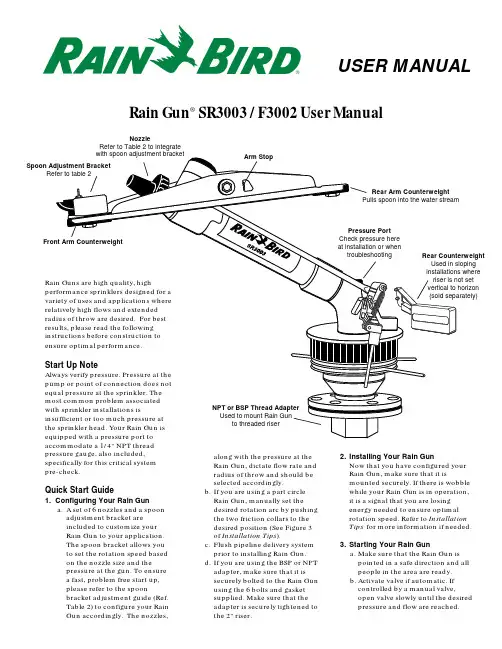
along with the pressure at the Rain Gun, dictate flow rate and radius of throw and should be selected accordingly.b.If you are using a part circle Rain Gun, manually set the desired rotation arc by pushing the two friction collars to the desired position (See Figure 3of Installation Tips ).c.Flush pipeline delivery system prior to installing Rain Gun.d.If you are using the BSP or NPT adapter, make sure that it is securely bolted to the Rain Gun using the 6 bolts and gasket supplied. Make sure that the adapter is securely tightened tothe 2" riser.USER MANUALpressure gauge, also included,specifically for this critical system pre-check.Quick Start Guide1. Configuring Your Rain Guna.A set of 6 nozzles and a spoon adjustment bracket are included to customize your Rain Gun to your application.The spoon bracket allows you to set the rotation speed based on the nozzle size and the pressure at the gun. To ensure a fast, problem free start up,please refer to the spoonbracket adjustment guide (Ref.Table 2) to configure your Rain Gun accordingly. The nozzles,Rain Gun ® SR3003 / F3002 User Manual2.Installing Your Rain GunNow that you have configured your Rain Gun, make sure that it ismounted securely. If there is wobble while your Rain Gun is in operation,it is a signal that you are losing energy needed to ensure optimal rotation speed. Refer to Installation Tips for more information if needed.3.Starting Your Rain Guna.Make sure that the Rain Gun is pointed in a safe direction and all people in the area are ready.b.Activate valve if automatic. If controlled by a manual valve,open valve slowly until the desired pressure and flow are reached.Table 1 – Performance DataSR3003 / F3002 Configuration DetailsNozzle SelectionSelect one of the six nozzles provided based on your performance requirements,available water pressure (at the Rain Gun), and flow capacity. Refer to Table 1and Figure 1.Installation TipsParts Diagram and DescriptionShould you experience operating difficulties, here are some tips that may apply to your application. For further assistance, please record the date code, the serial number on the elbow, and the pressure at the gun, and call your Rain Bird Dealer or the toll free Rain Bird number listed at the back of this guide.Rain Gun does not rotateor rotation speed is too slow •Install a 1/4" pressure gauge into the Rain Gun pressure port and verify adequate operating pressure. Refer to Spoon Bracket Adjustment guide (table 2) for proper configuration of spoon bracket based on nozzle size. Also check the spoon and the arm for damage.•If pressure is below specification and the Rain Gun is properly configured, decrease the nozzle size to increase pressure at the gun.•If pressure is lower than it was at installation, check for obstructions in the water line. You may be able to flush obstructions from the sprinkler and water line by removing the nozzle and turning on the water.•If pressure is still low after removing obstructions, and your Rain Gun still does not rotate, you may need to add a booster pump or increase pressure in another way.Rotation speed too fastInstall a pressure gauge at the RainGun pressure port and refer to SpoonBracket Adjustment guide (table 2) forproper configuration of spoon bracketto nozzle size. Also check the spoonfor damage. For proper operation, theoperating pressure at the gun shouldnot exceed 100 psi.Rotation speed varies fromone direction to another•Check that the spoon is properlyinstalled on the arm.•Check that the arm is not bent.•Check that the nozzle is properlyinstalled in the nozzle housing.It should be seated squarely.•Check the condition of the spoon.If broken, it will need to bereplaced.Gun does not reverse•Install a pressure gauge at the RainGun pressure port and refer toSpoon Bracket Adjustment guide(Table 2) for proper configurationof spoon bracket to nozzle size.Pressure at gun should not exceed100 psi.•Check trip mechanism by manuallyoperating it. Operation should befree and smooth.•Check trip mechanism spring. Itmust have tension and be properlyinstalled.•Check bushings at the tripmechanism. They must be cleanand not damaged.Arm stroke frequency istoo high•Make sure pressure is not above100 psi.•Make sure the front armcounterweight is installed(below spoon).•Make sure the rear armcounterweight is installed.Gun rotation slows downover time•Refer to first troubleshooting tipabove for non-rotating or slowrotation.Trip stop mechanism is notholding the gun at thedesired arc•Make sure that the trip stops arenot loose by pushing against themwith your finger. (See Figure 3)•Turn your gun manually to the tripstops. They should hold when thetrip lever pushes against them.•If your Rain Gun has recently beenre-assembled, make sure that thetrip lever was not reinstalled inbetween the trip stops. This willopen the trip mechanism and notstop the Rain Gun.Arm does not move• Check the pressure at the gun•Check that the nozzle is properlyinstalled on the nozzle housing•Make sure that the nozzle retaineris tightened•Check that the spoon is not broken•Check that the mechanical stop(arm stop) on the arm is notdamaged•Check that the arm is not bent Troubleshooting TipsRain Gun® WarrantyAgricultural ApplicationsOur latest generation of Rain Guns is built on a legacy of knowledge, trust, and feedback from end users like you.Our warranty is simple and in line with Rain Bird’s reputation as the most reliable agricultural sprinkler in the world.To back up our claim, we offer the best warranty in the agriculture industry. For all agricultural applications, we offer a three year, no questions asked warranty including free service or parts replacement. Non-agricultural ApplicationsWe understand that Rain Guns are often utilized in applications that may be more demanding than general agricultural applications. In these circumstances, Rain Bird offers an eighteen month warranty including free service or parts replacement, but excludes coverage in the following general applications or environments:• Electrolytic conditions, such as high salt environments or salt water spray applications• Applications where environmental conditions are not compatible with the materials used in Rain Guns• Caustic or corrosive chemical conditions or spray applications• Abrasive fluid spray applicationsRain Bird International, Inc.145 N. Grand Ave.Glendora, CA 91741-2469Phone: (626) 963-9311Fax: (626) 963-4287Rain Bird Agri-Products Co. 633 W. Foothill Blvd. Glendora, CA 91741-2469 Phone: (800) 435-5624 Fax: (626) 852-7310 ® Registered trademark of Rain Bird Sprinkler Mfg. Corp.© 2002 Rain Bird Sprinkler Mfg. Corp. 7/02PN L357。
喷水式雨水收集系统用户手册说明书

The Implementation of Zapira Portable by Maximizing the Potential Source in Rural AreaIka Febriana Wati Elementary and Preschool Education Department State University of Malang, Indonesia************************Eka Ajeng Fabela Elementary and Preschool Education Department State University of Malang, Indonesia************************Yunita Miftahul Jannah Elementary and Preschool Education Department State University of Malang, Indonesia*********************************YuniawatikaElementary and Preschool Education Department State University of Malang, Indonesia*********************.idAbstract: The electrification ratio in Indonesia reached 98.3%. Power plant technology innovations are needed, is it can be applied in rural areas with more environmentally friendly energy sources. One of them is rainwater. This is supported by the average rainfall in Indonesia which is quite high, which is 1000-4000 mm/year. The right innovation to be applied in the rural area is Zapira Portable. Zapira Portable is a portable scale household power plant that utilizes potential rainwater energy as a source of energy. The purpose of this activity program is 1) to create a device with potential rainwater energy generation, 2) to create portable power plants for household scale, and 3) to maximize electricity distribution in the 3T area. Implementation methods of Zapira Portable development include: 1) literature study, 2) design, 3) analysis of equipment and material requirements, 4) making devices, 5) implementation, 6) determination based on the results of implementation tests, and 7) evaluation. The results achieved are in the form of Zapira Portable device design, Zapira Portable device, video from device usage, Manual Book of Zapira Portable, validation of Zapira Portable devices, and testimonials. Keywords: implementation, zapira portable, potential source, rural areaI.INTRODUCTIONCommunity life cannot be separated from electricity. Based on data from the National Electricity Company in 2018 on its website www.pln.co.id, more than 3,660 villages in Indonesia have not yet been electrified. The shortcomings in electricity distribution mostly occur in the Foremost, Outermost, Disadvantaged (rural area) regions. Reporting from data from the Ministry of Energy and Mineral Resources, the electrification ratio in Indonesia reached 98.3%.The government conducts electricity distribution through the use of coal as the main material for electricity generation. However, this effort has a negative impact in the form of air pollution, public health problems, and environmental damage. Power plant technology innovations are needed that can be applied in 3T areas with more environmentally friendly energy sources. One of them is rainwater. This is supported by the average rainfall in Indonesia which is quite high, which is 1000-4000 mm/year.The right innovation to be applied in the rural area is Zapira Portable. Zapira Portable is a portable scale household power plant that utilizes potential rainwater energy as a source of energy. By adopting the principle of Micro-Hydro Power Plant (PLTMH), rainwater from gutters will be accommodated in a reservoir and flow rotates the turbine. This turbine rotation is processed in a generator to finally be able to produce electrical energy. The use of this technology is quite easy and abundant supply of rain energy.In 2015, Lutfi et al, students of the Depok Cakra Buana Vocational School created a rainwater hydroelectric power plant. But the results are small and the search for material is quite difficult. Whereas in 2017, there was the idea of a Microhydro at Home Power Plant (POPMIH) by Semarang State University students. But this is still a concept and there is no actual implementation. When compared with the two previous findings as well as the Microhydro Power Plant (MHP), Zapira Portable is cheaper and easier to find its components, its function can be proven, devices are portable, and can be used for household scale. Zapira Portable which uses rainwater has the potential to become a wearable, portable and free energy power plant. It is expected that this tool can maximize electricity distribution in the rural area and can be operated by anyone.The purpose of this activity program is 1) to create a device with potential rainwater energy generation, 2) to create portable power plants for household scale, and 3) to maximize electricity distribution in the rural area.II.METHODThe method for implementing the Zapira Portable development program is as follows.A. Literature StudyLiterature studies are carried out to update facts in the field and minimize the risk of device dysfunction. The literature study was carried out by observing the electrical installation conducted at the Surabaya State Shipping Polytechnic. To strengthen the determination of components, the team conducted consultations with mechanical and electrical experts, namely Ms. Amal Ma'rifatul Maghfiroh from Bojonegoro University.5th International Conference on Education and Technology (ICET 2019)B. DesignZapira Portable is designed with a shape that can be assembled and can be placed in all buildings that have gutters. There are two main parts of the device design, namely the pipe-shaped outer part of the device to be placed in the rain water channel and the inner device which is packaged in a beam-shaped box measuring about30 cm x 20 cm x 15 cm.C. Analysis of Tools and DataBased on the analysis of the tools that have been carried out, the Zapira Portable device consists of material tools and materials according to Table I as follows.Table ITools and materials.Materials Details Qty Turbine 12 Blade 1Pipe PVC, T-Shape, diameter 2,5 dim 1Motor Generator •DC tipe 775 12 V•Motor Diameter: 44.8mm•Motor Length: 72mm•Output Shaft: 5mm•Output Length: 21mm•Screw Hole: M4•Screw Pitch: 29.5mm•Weight: 446 gram•Speed: 400 RPM•Current: 1.8A1Controller •Type PMW•Available ports for generators,batteries, and loads•Available buttons and LCD display1Voltmeter Digital 1Dry Battery 12 V 7.2 Ah 1 Banana plug - 10 pairs LED DC 12 V 3 Watt 0.25 A 5 Acrylic Milky white, thick 5 mm 3 m2 Brass Hinges 2In addition to analyzing tools and materials, data analysis was also carried out. Data from BMKG, the average rainfall in Indonesia is 5-8 dm3/minute. The majority of the roofs of houses in Indonesia are in the form of prisms with their sides divided into 2 equal widths with one gutter on each side. The average roof area in Indonesia ranges from 36-120 m2. If averaged, the roof area is 78 m2, so one side of the roof of the house ranges from 39 m2. If the area of the roof that flows rainwater to the gutters is considered to be a cross-sectional area, then the water discharge on the gutter to fill the reservoir can reach 195-312 dm3/minute with the following calculation.Q = V x A (V = Rainfall, A = Cross-Section Area )Q = 5 s/d 8 x 39Q = 195 s/d 312 dm3/m = 3,25 x 10⁻³ m3/s s/d 5,2 x 10⁻³ m3/sThe potential power that can be generated from the Zapira Portable device is influenced by the water discharge (m3 / s) and head (the height of the fall of water) (m). If the head is 1.5 m, the power potential reaches 1.16 to 1.86 Watts per second according to the calculation as follows.P = η x g x Q x hP = 0,95 x 9,8 x 8,3 x 10-5 s/d 1,3 x 10-4 x 1,5P = 1,16 x 10⁻³ s/d 1,86 x 10⁻³ kW = 1,16 s/d 1,86 Watt. D. Making a DeviceMaking the device starts with print designs, then install pipes, install turbines with generators in pipes, make storage boxes, make generator sockets and load, install digital voltmeter, connect components with the controller, and install dry batteries.E. ImplementationThe Zapira Portable device is designed to be installed on rainwater pipes or gutters. Gutter can be modified to obtain maximum water discharge by applying the principle of velocity. The lower part of the gutter is added to the water reservoir so that the water discharge coming out to the Zapira Portable pipe remains stable. Implementation is done by installing a Zapira Portable device in a house building. If the season does not support the occurrence of rain, the device can be used in a place that has a type of water flow with the discharge of rainwater from gutters.F. Test ResultsThe test results obtained from the calculation of the power generated based on time, rainwater discharge, and rotation on the generator. The use of maximum power is also a consideration of tool evaluation later. If the test results meet the feasibility, the device is ready to be mass-produced to achieve its purpose as an electricity distribution device.G. EvaluationEvaluation includes tool functionality, tool effectiveness, tool shortcomings, tool development potential. Evaluation is obtained after the tool has been implemented and through the calculation process to get the test results.III.RESULTSThe results achieved in accordance with the development of Zapira Portable are as follows.A. DesignIn the design of the device there are 7 main components (figure 2) that make up the device. These parts include 1) T PVC pipe, 2) turbine, 3) 12 volt DC generator, 4) power storage packaging box, 5) PMW type controller, 6) dry battery, 7) digital voltmeter.(a)(b)(c)Figure 1. Top view design (a), front view (b), side view (c) Zapira Portable installation is located under the rainwater drain pipe or commonly called gutters. Effective waterway design to optimize the performance of Zapira Portable is a gutter that is horizontal along the end of the roof leading to a pipe under which a water reservoir is installed. Zapira Portable is installed on a pipeline under the reservoir. It is intended that the rain water that rotates the turbine has a stable discharge.Figure 2. Device Installation DesignB. Zapira Portable Device.The device is made based on the design that has been made. The outer circuit is in the form of a T pipe with a size of about 20 x 15 x 8 cm. Whereas box packaging has a storage capacity of 30 x 20 x 15 cm.Figure 3. Zapira Portable DeviceThe way Zapira Portable works starts from water that falls on gutters with a height from the roof of about 1.5 m and has a flow of about 5 to 8 dm3 / minute. This water will drive the generator. The power that enters through the PMW controller will be stabilized so that the voltage entering the battery is stable. Through this controller you can also calculate the amount of power and voltage in the battery so that it can disconnect the incoming current automatically when it is fully charged.Figure 4. Working Scheme of Zapira PortableC. Video of Device UsageThe device video shows a tutorial from the operation of Zapira Portable. This video can be an overview of how the device works. This video can also be proof of the functioning of the device.D. Manual Book of Zapira PortableThe manual book contains steps to operate the device.fonts are prescribed; please do not alter them. You may note peculiarities. For example, the head margin measures proportionately more than is customary. Thismeasurement and others are deliberate, using specifications that anticipate your paper as one part of the entire proceedings, and not as an independent document. Please do not revise any of the current designations.Figure 5. Manual Book of Zapira PortableE. Validation of the Zapira Portable DeviceValidation is needed to strengthen the device in design and function. Some of these experts include the East Java ESDM Service, PT. PLN East Java Unit, and BMKG Malang.F. Testimonials of Zapira Portable Devices Testimonials are needed to find out the opinions of people who feel the benefits directly. The testimony that has been done is towards the community represented by the Chairperson of RW / RT 01/01 in Ngadi Village, Kediri and the Village Head of Semen, Blitar.IV.DISCUSSIONBased on the analysis of the results of the data, it is obtained the voltage and current that influence the amount of power produced by the Zapira Portable device. The factor that distinguishes the results of this implementation test is the water debit. From the calculation of the results, it can be seen how long the battery is needed to fill up the battery.Table IIImplementation resultsExp. Voltage(V)Influx(I)Debit(Q)Potency(P)BatteryChargingTime (h)1 1,9 V 1 A 8 ltr/m 1,9 watt 4,55 hours2 1,7 V 1 A 6 ltr/m 1,7 watt 5,1 hours3 1,4 V 1 A 4 ltr/m 1,4 watt 6,15 hoursBased on the specifications of the battery, it can be known that the usage time is in accordance with the power released. The battery specifications used in Zapira Portable are Panasonic dry batteries. 12 V LC-V127R2NA DC, 7.2 Ah / 20 HR. Suppose that the battery is only loaded with a 3 watt / 12 V DC LED light, so the battery usage time is as follows.Known:Load (P) = 3 watt(V) = 12 VThen, I = P : V= 3 : 12I = 0,25 AUsage Time (h) = Ah : I= 7,2 Ah : 0,25 A= 28,8 hours= 28,8 hours – battery deficiency (20%)= 28,8 hours – 5,76 hours= 23,04 hoursSo, the usage time for 3 watt /12 V DC LED lights is 23 hours 2 minutes 24 seconds..V.CONCLUSIONBased on the results of testing, Zapira Portable is able to turn up to 5 loads. This is also what determines the number of sockets on the controller. Zapira Poertable is appropriately applied in Indonesia because the required water discharge is in accordance with the rainfall in Indonesia, which is 4-8 liters/minute. The potential power generated is also quite large, which is up to 1.9 watts. This is what makes Zapira Poertable feasible to be a solution to the lack of electricity distribution in rural areas.ACKNOWLEDGMENTGratitude to Allah subhanahu wa ta'ala for giving His mercy so that we can finish the development and this article nicely. Thank you to the Ministry of Research, Technology and Higher Education for their trust in funding the development of the Zapira Portable device. Thank you to all the officials of the State University of Malang for their support and opportunities. Thank you to the experts who are the validators and sources of liturgical studies. And thanks to the people who have shown support through testimonials from the Zapira Portable device.REFERENCES[1]Anuar.Khairil., dkk. 2015.Analisis Kualitas Air Hujan SebagaiSumber Air Minum Terhadap Kesehatan Masyarakat(Studi Kasus di Kecamatan Bangko Bagansiapiapi).Jurnal Dinamika Lingkungan Indonesia.Vol. 2, No. 1, hh. 32-39.[2]Ceri Steward Poea, G.D. Soplanit & Jotje Pantung. 2013.Perencanaan Turbin Air Mikro Hidro Jenis Pelton untuk Pembangkit Listrik di Desa Kali Kecamatan Pineleng dengan Head 12Meter. Manado: Universitas Sam Ratulangi.[3]Fox & Mc Donald. 2011.Introduction to Fuild Mechanic, EightEdition SI Version.Singapura: John Wiley & Sons,Inc.[4]Irawan,Heri., dkk. 2018. Analisis Performansi Sistem PembangkitListrik Tenaga Air Jenis Turbin Pelton Dengan Variasi Bukaan Katup Dan Beban Lampu Menggunakan Inverter.Jurnal Hasil Penelitian. Vol. 3, No. 1, hh. 27-31.[5]Juwito, A. F., dkk. 2012.Optimalisasi Energi TerbarukanpadaPembangkit Tenaga Listrik dalam Menghadapi Desa Mandiri Energi di Margajaya.Jurnal Ilmiah Semesta Teknika.Vol.15, No. 1, hh. 22-34.[6]Kementerian Energi dan Sumber Daya Mineral Republik Indonesia.2018.Menteri ESDM: 98,3% Penduduk Sudah Menikmati Listrik.https://www.esdm.go.id. diakses pada tanggal 12 November 2018.[7]Lampiran Peraturan Menteri Negara Lingkungan Hidup No. 12Tahun 2009.[8]PT PLN (Persero). 2018. RUTL PT PLN (Persero)2018-2027.https://www.pln.co.id. Jakarta: PT PLN (Persero).[9]Samsul, Kamal & Prajitno.2013.Evaluasi unjuk kerja turbin airpelton terbuat dari kayu dan bambu sebagai pembangkit listrik ramah lingkungan untuk pedesaan.Jurnal Manusia dan Lingkungan, Vol. 20, No. 2, hh.190-198.。
Wabco 器材预湿吸干器说明书
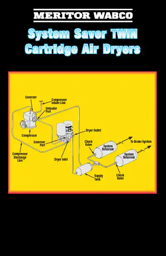
GovernorCompressorCompressor Discharge LineDryer InletGovernorPortCompressor Intake Line Unloader PortDryer OutletCheck ValveSystem ReservoirSystem ReservoirCheck ValveSupply TankTo Brake SystemFor more information, see Maintenance Manual No. 35or dial our toll-free number:800-535-5560SOLUTIONPOSSIBLE CAUSECONDITIONRegeneration cycle too short (less than 10 seconds).Increase air system capacity or reduce air demands.Check and replace pressure-controlled check valve as needed.Remove one-way check valve. Make sure pressure-controlled check valve is installed correctly.Remove regeneration valve and clean oil from diaphragm. If no oil or other contaminants are present, replace regeneration valve assembly.Inspect per manufacturer’s instructions and repair/replace as needed.High air system demands during compressor unloaded cycle.Pressure-controlled check valve not installed in system or not working properly.One-way check valve installed in system reservoir instead of, or with, pressure-controlled check valve.Regeneration valve not working.Air governor not working properly.No regeneration cycle. No airflow from purge valve after initial purge blast (dryer decompression).Verify proper dryer installation per system diagram.Replace regeneration valve.Remove one-way check valve.Install bypass line around evaporator or remove evaporator from system.Air dryer not connected to supply tank or connections reversed at dryer.Regeneration valve not working.One-way check valve installed in supply tank.Alcohol evaporator installed between dryer and supply tank.Air dryer purges too often, perhaps as frequently as every 15 seconds,accompanied by excessive cycling of the compressor.Repair air line.Repair air line.Repair leaks.Increase air system capacity or reduce air demand.Inspect and replace outlet check valve as needed.Replace regeneration valve.Replace air governor.Inspect compressor. Repair/replace per manufacturer’s instructions.Leak in line between governor and dryer port 4.Leak in line between supply tank and governor.Excessive air system leaks.Excessive air system demands.Outlet check valve not sealing.Regeneration valve not shutting off properly.Air governor has less than 16 psi range.Leaking air compressor unloader(s).Air dryer does not purge when compressor unloads (no blast of air from purge valve).Repair air line.Replace purge valve.Inspect air governor. Repair/replace per manufacturer’s instructions.Check for air leaks in system and repair as needed. If no leaks in system, check compressor output. Repair/replace per manufacturer’s instructions.Air line between governor and air dryer port 4 kinked or plugged.Purge valve stuck closed.Air governor not working properly.Cut-out pressure never achieved by air compressor.Rapid “spitting” of air from purge valve in smallamounts. Frequency varies with engine speed.Replace air dryer with an SS1200E air dryer.Inspect compressor. Repair/replace per manufacturer’s instructions.Holset E-Type compressor used, but non-1200E dryer pressor not completely unloading when cut-out pressure is reached.Air leak at turbo cut-off valve vent. Hole burned in piston.Move dryer farther from compressor. Add additional compressor discharge line before air dryer. Add cooling coil or heat exchanger before air dryer.NOTE: Inlet air temperature must not exceed 175°F.Temperature of air coming into dryer is too high — not enough cooling takes place before dryer inlet.Air leak at turbo cut-off valve vent.Install lip seal correctly.Inspect valve bore for wear. If a new turbo cut-off valve does not seal in a clean, lubricated bore, replace the air dryer.Lip seal installed upside-down on piston. Lip must face UP (towards dryer).Valve bore worn excessively.Air flows out of purge valve entire time compressor is unloaded.Replace turbo cut-off valve.Turbo cut-off valve not sealing.Regeneration cycle too long (more than 30seconds), accompanied by loss of pressure in the supply tank.Inspect and replace outlet check valve as needed.Replace regeneration valve.Outlet check valve not seating.Regeneration valve not shutting off regeneration airflow.TP 97100Revised 9/9816579/24240Air dryer frozen (water collecting in base of dryer is freezing).Check for a blown fuse. Repair heater circuit.NOTE: There must be power to the heater connector the entire time the vehicle’s ignition is “on.”Repair cause of low voltage, such as poor electrical ground, bad connections, corroded wire splices, etc.Replace heater assembly.Replace with correct voltage air dryer.No electrical power to heater connector.Low voltage to heater connector.Heater assembly not working.Wrong voltage air dryer used; i.e., 12-volt air dryer used in a 24-volt system.No air pressure build-up in system.Ensure compressor discharge line is plumbed to air dryer port 1, and air dryer port 21 is connected to vehicle’s supply tank.Ensure dryer port 4 line is connected to the “UNL” port of the air governor.Inspect governor per manufacturer’s instructions. Repair or replace as needed.Locate leak(s) and repair.See purge valve conditions listed in this chart.Air dryer not plumbed correctly (connections reversed).Wrong air line connected to dryer port 4.Air governor not working properly.Air system leaks, such as compressor discharge line, air dryer, reservoirs, brake or suspension valves, etc.Air dryer leaks from purge valve.Water in tanks; often following aftermarket installation or when dryer is a replacement for a competitive brand.Install pressure-controlled check valve in secondary tank.Remove one-way check valve so that only the pressure-controlled check valve is installed between the secondary tank and supply tank.Pressure-controlled check valve not installed in correct tank or not installed at all.Pressure-controlled check valve properly installed, but one-way check valve not removed.Water, oil, or sludge in air system tanks.Replace desiccant. Inspect compressor per manufacturer’s instructions.Replace air dryer with an SS1200E air dryer.Desiccant contaminated with oil.Holset E-Type compressor used, but non-1200E dryer installed.Water in system tanks, everything else checks out okay.Review application guidelines. For assistance, call Meritor Customer Support Center at 1-800-535-5560.Dryer not suitable for application.。
ECON-ZIP-SDLF 单干式热交换器系统说明书
INSTRUCTION MANUALECON-ZIP-SDLF; ZIP PACKECON-ZIP-SDLF; ZIP PACKSingle Dry Bulb with DCV Capability and LF Spring Return Actuator71766-00001_AApplicationThis kit offers all the components to retrofi t an economizer on a direct expansion RTUs up to 12 tons while utilizing single dry bulb changeover strategy. In this, the ZIP Economizer will compare outside air dry bulb temperature to a fi xed setpoint , or high limit changeover temperature,(based on your climate zone) to control the economizer cycle. Onetemperature sensor will be place on the outside damper, and the other in the supply duct. That high limit changeover temperature is adjustable.When the included energy module is used (ECON-ZIP-EM), the following options become available: demand control ventilation, pre occupancy purge, power exhaust, remote damper position override, fan speed switch.ECON-ZIP-BASE(2) ECON-ZIP-10KECON-ZIP-EM LF24-SR and Retrofi t Kit03/15 - S u b j e c t t o c h a n g e . © B e l i m o A i r c o n t r o l s (U S A ), I n c .2ZIP EconomizerSetup and ConfigurationQuick SetupFunctions1. “Monitor Live Conditions” is used to display settings and live values.2. “Settings” is used to parameterize the ZIP Economizer. (Note: Devices 1 is for CC1, CC2, EF, IF; Devices 2 is for OAH, RAH)3. “Present Devices” is used to verify that the ZIP Economizer's Auto Detected connections are terminated properly. If connected device is not shown,verify wiring. If wiring has continuity and device is verifi ed operational re-enter “Settings” and enable missing device by changing from “Auto” to “Available” or “Installed”.4. “Alarms” is used to view current and historical alarms and delete inadvertently caused alarms.5. “Service and Commissioning” submenu is used to operate the RTU in “Manual Mode” or to perform “Acceptance Test”. “Settings” must to be completed to access.6. “Status” is a display of the current operating mode. It can be accessed by pressing ”esc”. The action of pressing any key will drop the user downfrom Status to the next level, so repeatedly pressing “esc” will toggle the display between Status and Monitor Live Conditions. (Note: If status “Setup incomplete” is displayed the RTU cooling operation will be disabled and additional parameters must be set to achieve “Setup complete”.)1. Shut off power to RTU before beginning installation.2. Note orientation, opening rotation, and spring return rotation of damper assembly. Mount Actuator to Outside Air and Return Damper assembly. To ensure tight outside air shutoff; while tightening actuator clamp push damper closed.3. Terminate required Inputs and Outputs(I/O): For the ZIP Economizer to function correctly, the following I/O, at a minimum, are required to be terminated, wired, and functioning (R, C, Y1, Y2, G, CC1, OAT, SAT, ACT1,ACT2, ACT3, ACT5). See wiring diagrams.4. Sensor confi guation: The ZIP Economizer automatically detects sensors attached and automatically confi gures for single dry bulb, single enthalpy,differential dry bulb and differential enthalpy.“Settings” is the menu displayed when the ZIP Economizer is fi rst powered. Press “OK” to parameterize required settings. Reference above Keypad Key defi nition instructions and navigate as needed.WARNING Live Electrical Components!During installation, testing, servicing and troubleshooting of this product, it may be necessary to work with live electrical components. H ave a qualifi ed licensed electrician or other individual who has been properly trained in handling live electrical components perform these tasks. Failure to follow all electrical safety precautions when exposed to live electrical components could result in death or serious injury.03/15 - S u b j e c t t o c h a n g e . © B e l i m o A i r c o n t r o l s (U S A ), I n c .3Quick Setup1. ZIP Code US or Canada (sets the free cooling changeover high limit and temperature units F/C)a. When the Zip Code submenu is displayed enter “OK” to begin “US” Zip Code parameterization. If “Canada” Postal Code is desired press the up/ down arrow to access.i. Press OK to access digit 1 (fl ashing) then use the up/down arrow to parameterize; enter OK when complete. Repeat until all digits are complete. If a mistake is made press “esc” and repeat frombeginningii. When all Zip Code or Postal Code digits are entered press“esc” to move up a level then press the up/down arrow to access next settings parameter.2. Vent Min Pos (Outdoor Air Damper Ventilation Minimum Position) a. When the “Vent Min Pos” submenu is displayed press “OK” to parameterize (fl ashing).b. Use the up/down arrow to parameterize, press “OK” when complete. The actuator will immediately drive the damper to the minimum position.3. Additional Parameters may require setting. The ZIP Economizer will auto-detect added Devices such as a CO2 sensor etc. When the ZIP Economizer detects a new device, it will prompt the user in the Status level; navigate to Settings and parameterize blank fi elds. If the devices are connected upon fi rst start up their settings will require parameterization then. 4. When all parameters have been set, the ZIP Economizer will show “Setup Complete” if there are still parameters to set, there will be no action. You can verify by pushing esc until status level is reached and it will display “Setup Incomplete”. If this is the case, re-enter settings menu and use up down arrows to fi nd the parameter with blank fi elds and parameterize as described above.Note: you may enter parameters in any order - eg: Vent min Pos before ZIP Code - If the RTU is a heat pump or uses a 2 speed indoor fan, these paramaters should be enabled fi rst, otherwise the logic may go to Setup Complete prematurely.The ZIP Economizer has built in commissioning processes found in Acceptance Test.1. Economizer Test. Use “Economizer Test” to verify RTU IntegratedEconomizer operation. Navigate to the “Service and Commissioning” menu, press “OK”; press the down arrow to access “Acceptance Test”. Press OK again when “Economizer Test” appears. Press “OK” again to confi rm running test. Follow prompts during test. This test will open damper to 100%, enable power exhaust fan (if connected), enable 1st stage of Mechanical Cooling, reverse this process and then drive to Vent MinPosition. When used with a Belimo actuator, the actuator will speed up to reduce test time.2. Manual Mode is used to override outputs after entering a “Timeout” duration.3. Damper Scaling. The test will re-scale the control signal range tomaximum resolution (0-100%) over the calibrated (reduced) angle. When using a Belimo actuator, the actuator will speed up to reduce test time.Note: Failure to identify obstructions or improper setup of damper assembly may result in an improper scaling and operation of the damper.)Note: Additional testing can be found on page 36 of this document.1. When all entries have been completed, the ZIP Economizer will switch to Status display and show “Setup Complete”, and will immediately show a “Damper scaling starts in 10secs” and will countdown to 0 (be aware, at 0 the damper will start to move at high speed ) . A message will scroll saying “Damper scaling for better operation if obstruction is present rescale damper in commissioning menu”. (For detailed instructions on this – please see the section “Service and Commissioning” below. This will open damper to 100% (re-scale control signal if needed). (Note: failure to identify obstructions or improper setup of damper assembly may result in an improper scaling and operation of the damper.)Once scaling is complete, a message will appear saying “Damper scaling successful”. The ZIP will then show “maximum at 80° = 100%” That message will show maximum rotation of the damper. This process ensures the damper is always operating and displayed from 0-100%.2. Once the message has appeared, the actuator immediately closes the damper and a countdown begins, until the unit starts to operate in Automatic Mode (be aware, when countdown complete, the RTU will respond to thermostat calls which may enable mechanical cooling).ZIP EconomizerSetup and Configuration03/15 - S u b j e c t t o c h a n g e . © B e l i m o A i r c o n t r o l s (U S A ), I n c .ZIP Economizer Menu Structure TablesSettingsZip Code1US00000 5 Digit NumSetting of either US or Canada code required for Economizer Operation.Setting the ZIP code automatically confi gures the economizer high limit changeover temperature to comply with local energy code. If the user desires a differenthigh limit value, this can be modifi ed in the “settings” menu under “high limitmodifi cation”.Canada000000 6 Digit Alpha/NumSetting of either US or Canada code required for Economizer Operation.Setting the ZIP code automatically confi gures the economizer high limit changeover temperature to comply with local energy code. If the user desires a differenthigh limit value, this can be modifi ed in the “settings” menu under “high limitmodifi cation”.Heat Pump Op Heat Pump Op OffOffHP (O) = pow = CoolHP (B) = pow = HeatHP (W1) = pow = HeatIf the RTU that the economizer is installed in, is a heat pump, then this value shall beset to one of the following:(O) = Reversing valve powered for cooling.(B) = Reversing valve powered for heating.(W1) = Standard thermostat, reversing valve controlled by internal RTU defrost board.Compressor Qty8Number ofCompressorsAuto2No compressor detectedCompressor 1 detectedCompressor 2 but noCompressor 1 detectedCompressors 1 and 2detectedCompressors 1 and 2selectedCompressor 1 selectedMessage appears only during initial setup. If No Compressor is detected, verify wiring,check continuity, if all is correct, push OK to set quantity.If only 1 compressor is detected, and there are 2 installed verify wiring, checkcontinuity, if all is correct, push OK to set quantity.Devices 1 CC1, CC2, IF, EF, (as connected)Fan 2 Speed4Auto2Auto, Available, NotAvailableAllows for 2 speed indoor fan control circuit (IF) to be automatically detected whenwired. If circuit is not automatically detected, the functionality can be manuallyenabled by choosing “available.” If there is a desire to disable functionality for anyreason, the operator can choose “not available” and the operation of the economizerwill function as if the device is not installed or confi gured.Compressor Qty3Auto2Auto, 1, 2Allows for up to 2 compressor circuits (CC1, CC2) to be automatically detected whenwired. If circuit is not automatically detected, the functionality can be manuallyenabled by setting compressor Qty to 1 or 2.Exh Fan Install4Auto2Auto, Installed, NotInstalledAllows for exhaust fan control circuit (EF) to be automatically detected when wired.If circuit is not automatically detected, the functionality can be manually enabledby choosing “available.” If there is a desire to disable functionality for any reason,the operator can choose “not available” and the operation of the economizer willfunction as if the device is not installed or configured.Devices 2 OAH, RAH, (as connected)OAH5Auto2Auto, Installed, NotInstalledAllows for the Outside Air Humidity Sensor to be automatically detected when wiredfor enthalpy change over strategy. If the sensor is not automatically detected, thehumidity sensor can be manually enabled by choosing “installed.” If there is a desireto disable functionality for any reason, the operator can choose “not installed”,and the operation of the economizer will function as if the device is not installed orconfigured.RAH5Auto2Auto, Installed, NotInstalledAllows for the Return Air Humidity Sensor to be automatically detected when wiredfor differential enthalpy change over strategy. If the sensor is not automaticallydetected, the humidity sensor can be manually enabled by choosing “installed.” Ifthere is a desire to disable functionality for any reason, the operator can choose “notinstalled,” and the operation of the economizer will function as if the device is notinstalled or configured.3/15-Subjecttochange.©BelimoAircontrols(USA),Inc.45Vent Min Pos 1Vent Min Pos _ _% 0-100%Setting the minimum position required for Economizer Operation.This is where the outdoor damper minimum position is set. This is the position that the damper will travel to during occupied periods (when terminal G on economizer is powered). The amount of outdoor air is different per application. Please consult local ventilation codes. This setting is typically related to a calculation that determines amount of fresh air for building area and people (Vbz = Ventilation Breathing Zone per ASHRE 62.1). Actual airflow at a given position should be verified by field measurement.DCV Min Pos 4DCV Min Pos _ _%0% - Vent Min Pos %This is the Demand Control Ventilation minimum position. The DCV min pos is a value always less than the design ventilation position. This is the position that the damper will travel to during occupied periods (when terminal G on economizer is powered)when the measure CO2 Value is below the DCV PPM Set Pnt. The amount of outdoor air is different per application. Please consult local ventilation codes. This setting is typically related to a calculation that determines amount of fresh air for building area (Ra = outdoor airflow rate required per unit area per ASHRE 62.1) to allow continue flushing of VOCs during occupied periods. Actual airflow at a given position should be verified by field measurement.DCV PPM Set Pnt 4DCV PPM Set Pnt _ _ppm 500 - 2000 ppmThis is the CO2 concentration that is desired to maintain in the space. When the CO2sensor measures a concentration below this value, the damper control point will be reset and the damper will modulate towards DCV Min Pos. When the measured CO2 level increases above this value, the damper will start to modulate towards the Vent Min Pos to lower the CO2 in the space.2 Speed Fan Op 2 Speed Fan OperationOffOn OffIf the unit is factory installed with 2 speed fan capability, then this setting must be set to On to provide proper ventilation.Low Sp Vent Min 6Low Sp Vent Min _ _%"Vent Min Pos" % - 100%When a 2 Speed strategy is used to save energy, an additional Vent Min Pos needs to be entered for low speed operation due to less available static pressure from the fan. This position will be greater than Vent Min Pos, however equal the same measured airflow rate value.Low Sp DCV Min 6Low Sp DCV Min _ _%"DCV Min Pos" % - "Low Sp Vent Min" %When a 2 Speed strategy is used to save energy, an additional DCV Min Pos needs to be entered for low speed operation due to less available static pressure from the fan. This position will be greater than DCV Min Pos, however equal the same measured airflow rate value.Exh Fan On Pos 4Exh Fan On Pos _ _%0 - 100%This is where the desired enable point for exhaust fan operation is set. As the outdoor damper increases or decrease past this position, the exhaust fan will be turned on or off.Low Exh Fan Pos 6Low Exh Fan Pos _ _%0 - 100%When a 2 Speed strategy is used to save energy, an additional Exh Fan On Pos needs to be entered for low speed operation due to less available static pressure from the fan. This position will be greater than Exh Fan On Pos, however equal the same measured space pressure.Temp Unit Temp Unit °F °F, °CAllows the user to select Fahrenheit or Celsius temperature display. When the ZIP Economizer is set up with a Canadian Postal Code, the units are default to °C.Purge Enable 4Purge Control Off On, OffThis is where Pre-Occupancy purge control is enabled. Pre-Occupancy purge is a requirement in some codes to ventilate the building just prior to normal occupancy times. The function removes VOCs that have gathered in the building duringunoccupied period when the Outside air damper is normally closed. Purge Control requires using the expansion energy module and a thermostat or other time driven control that will enable supply fan and provide 24V to Aux 1 during the desired purge period. Setting of “Purge Dmp Set” is required for the function to work.Purge Dmp Set 4Purge Dmp Set _ _%0% - "Vent Min Pos" %This determines the position that the damper will open to during Pre-Occupancy purge. This position is usually based what will achieve the desired number of air changes.Remote Dmp Cntrl 4Remote Dmp CntrlOff On, OffThis is where an optional outdoor air damper position override can be enabled. Input into AUX2 is 2-10 VDC (2V damper closed - 10V 100% open). This function overrides all other damper position settings Except: not in Automatic, G not energized FP .ZIP EconomizerMenu Structure Tables03/15 - S u b j e c t t o c h a n g e . © B e l i m o A i r c o n t r o l s (U S A ), I n c .6ZIP EconomizerMenu Structure TablesHigh Limit Modification High Limit Dry BulbZIP Code Dependent 60-80°F 16-27°CIf the High Limit Change Over Setpoint that was determined by the ZIP Code setup is deemed to be not desirable for the application, then it can be modified here.With Differential Enthalpy, temperature can also be changed; offsets cannot. Note: a modification may result in less energy savings and non compliance with local energy code.High LimitFixed Enthalpy 528 BTU/lb 47 kJ/kg 25-28 BTU/lb 40-52 kJ/kg ZIP Code Dependent 60-80°F 16-27°C High Limit Diff Enthalpy30 BTU/lb 52 kJ/kg 25-30 BTU/lb 40-52 kJ/kg ZIP Code Dependent60-80°F 16-27°CSAT Y2 Limit SAT Y2 Limit On On, OffSAT Y2 Limit is an energy saving function that prevents 2nd stage to get engaged when the Supply Air Temperature is at 56.5°F or below. When "On" there will be 4 min delay from the time Y2 is on until the 2nd stage compressor will be enabled allowing 1st stage to try to satisfy SAT requirement. When “off”, 2nd stage is not limited and compressor delay is 10 seconds. This function saves energy by having one stage of cooling satisfy space cooling requirements.1. Required setting for Economizer operation. If the value is not set, outputs of the economizer such as compressors will not operate regardless of thermostat call.2. Attached Devices will be automatically detected and the related functionality will be enabled. When devices are detected, they will appear in the Present Devices menu and the Setup Settings menu will also automatically configure to display parameter to setup. For example, when an Exhaust Fan (EF) is detected, the "Exh Fan On Pos" will show in the menu and will require setup.3. At least 1 compressor is required (auto detected or chosen) for economizer to function.4. Requires the Energy Module connected and the accessory component powered, wired, and terminated to the Energy Module.5. Only visible when Humidity Sensor is present.6. Requires the Energy Module connected, 2 speed fan installed, and the accessory component or device powered, wired, and terminated to the Energy Module. 2 Speed Fan can be enabled in settings menu.7. Not visible when differential dry bulb or differential enthalpy change over strategies are used.8. Only present at initial setup.03/15 - S u b j e c t t o c h a n g e . © B e l i m o A i r c o n t r o l s (U S A ), I n c .。
朴素工具 PCX18115 5升 18.9升湿干吸吸气机用户手册说明书
Specifications..............................................................................................................2Package Contents......................................................................................................3Safety Information.......................................................................................................4Operating Instructions.................................................................................................6Care and Maintenance................................................................................................9Troubleshooting.........................................................................................................10Expanded View and Parts List...................................................................................11Warranty.. (12)PRODUCT SPECIFICATIONSWARNINGPower 120 V / 60 Hz / 8 AModel PCX18115Single Stage5 Gallon7 ft. x 1-1/4 in. / 2.1 m x 3.2 cm Gauge A.W.G.1412Motor Tank Capacity Hose Power cordExtension Cord Length Use only extension cords that are rated for outdoor use. Extension cords in poor condition or that are too small in wire size can pose fire and shock hazards. To reduce the risk of these hazards when using an extension cord, be sure it is in good condition and that the connection does not come into contact with liquid. To keep power loss to a minimum, use the following table to choose the minimum wire size extension cord.SJTW18AWG 6 ft. / 1.8 m Length0 - 15.2 m / 0 - 50 ft.0 - 30.5 m / 50 - 100 ft.4 56SAFETY INFORMATIONATTENTION IMPORTANT SAFETY INSTRUCTIONS & GROUNDING INSTRUCTIONSTo reduce the risk of fire, electric shock, or injury:When using an electrical appliance, basic precautions should be always followed, including the following: READ ALL INSTRUCTIONS BEFORE USING THIS APPLIANCE.Read all safety rules carefully before attempting to operate. Retain for future reference.1. Do not leave appliance when plugged in or when in operation. Unplug from outlet when not in use and before performing any service on it.2. Do not expose to rain. Store indoors.3. Always disconnect the plug from the wall outlet before removing the tank cover.4. Do not allow to be used as a toy. Close attention is necessary when used by or near children.5. Do not use with damaged cord or plug. If appliance is not working as it should, has been dropped, damaged, left outdoors or dropped into water, contact service center for assistance.6. Do not pull or carry by cord, use cord as a handle, close a door on cord or pull cord around sharp edges or corners. Do not run appliance over cord. Keep cord away from heated surfaces.7. Do not unplug by pulling on cord. To unplug, grasp the plug, not the cord.8. Do not handle plug or appliance with wet hands.9. Do not put any object into openings. Do not use with any openings blocked; keep the openings free of dust, lint, hair and anything that may reduce airflow.10. Keep hair, loose clothing, fingers and all parts of body away from openings and moving parts.11. Do not pick up anything that is burning or smoking, such as cigarettes, matches or hot ashes.12. Do not use without dust bag and/or filters in place.13. Turn off all controls before unplugging.14. Use extra care when cleaning on stairs.15. Do not use to pick up flammable or combustible liquids such as gasoline or use in areas where they may be present.16. Do not use the cleaner as a sprayer of flammable liquids such as oil-based paint, lacquers, etc.17. Do not vacuum toxic, carcinogenic, combustible or other hazardous materials such as asbestos, arsenic, barium, beryllium, lead, pesticides or other health endangering materials.18. Do not pick up soot, cement, plaster or drywall dust without filter and dust bag in place. These are very fine particles that may affect the performance of the motor or be exhausted back into the air. Additional dust bag is available.DANGERWARNINGNever operate this unit when flammable materials or vapors are present because electrical devices produce arcs or sparks that can cause a fire or explosion.SERVICING OF A DOUBLE-INSULATED WET/DRY VACUUMIn a double-insulated Wet/Dry Vacuum, two systems of insulation are provided instead of grounding. This means that no grounding is provided on a double-insulated appliance, nor should a means for grounding be added. Servicing a double-insulated Wet/Dry Vacuum requires extreme care and knowledge of the system and should be done only by qualified service personnel. Replacement parts for a double-insulated Wet/Dry Vacuum must be identical to the parts they replace. The double-insulated Wet/Dry Vacuum is marked with the words "DOUBLE-INSULATED" and the symbol (square within a square) may also be marked on the appliance.NOTE: Use only as described in this manual. Use only manufacturer's recommendedattachments.To reduce the risk of injury from electric shock, unplug power cord before servicing the electrical parts of the Wet/Dry Vac.If the supply cord is damaged, it must be replaced by the manufacturer or its service agent or a similarly qualified person in order to avoid a hazard.Remove the plug from the socket before performing maintenance. Before using themachine make sure that the frequency and voltage shown on the rating plate correspond with the mains voltage. Specifications and details are subject to change without prior notice. The accessories shown in the pictures may vary from model to model.19. Do not leave the cord lying on the floor once you have finished the cleaning job. It can become a tripping hazard.20. Use special care when emptying heavily loaded tanks.21. To avoid spontaneous combustion, empty tank after each use.22. The operation of a utility vacuum can result in foreign objects being blown into eyes, which can result in eye damage. Always wear safety goggles when operating vacuum.23. STAY ALERT. Watch what you are doing and use common sense. Do not use vacuum cleaner when you are tired, distracted or under the influence of drugs, alcohol or medication causing diminished control.24. This appliance is provided with double insulation. Use only identical replacement parts. See instructions for servicing double insulated appliances.25. Unplug before connecting the hose, nozzles, filters, or other accessories.WARNINGWARNINGWARNINGThis product is NOT to be used for filtering of pathogens, for example COVID-19. Follow all local, state and federal guidance on general cleaning practices.WARNINGOPERATING INSTRUCTIONSUNPACKING & SET-UP SUMMARYWARNINGor dusts, do not vacuum toxic materials.WARNINGThe operation of any utility vacuum can result in foreign objects being blown into the eyes, which can result in severe eye damage. Always wear safety eyewear complying with ANSI Z87.1 (or in Canada, CSA Z94.3) before starting operation.CAUTIONTo reduce risk of hearing damage, wear ear protectors when using the vacuum for extended hours or when using it in a noisy area.may have been shipped in the tank.2. Attach caster following the instructions as below:3. Before replacing power head, refer to this manual to4. Replace power head, and apply pressure with thumb to each latch until it snaps tightly in place. Make sure all lid latches are clamped securely.5. Insert the hose end into inlet of tank.6. Attach the extension wands to the end of the hose. Apply slight pressure until fitting is tight.7. Attach one of the cleaning accessories (depending on the cleaning requirements) on the extension wands. Twist slightly to tighten the connection.8. Plug the cord into the wall outlet. The vacuum is ready for use.9. Turn the unit “ON” by pushing the switch from position “O” to position “I”. The “O” is the “OFF” position and the “I” is the “ON” position.a. Invert dust tank, take the caster to align the tank bottom sinking place.b. Return dust tank assembly upright.DRY PICK-UPWET PICK-UPINSTALLING DISPOSABLE FILTER BAGNOTICENOTICEA dry filter is necessary to pick up dry material. If you use the vacuum to pick up dust when the filter is wet, the filter will clog quickly and be very difficult to clean. If the filter gets wet, replace it before continuing to do dry pickups.1. Slide the cardboard collar opening firmly onto the vacuum port deflector until it stops against the deflector wall.2. Position the bag so that it is distributed around the inside of the tank.3. Replace and secure the power head onto the tank.pickups.2. This wet/dry vac is equipped with a float mechanism which will rise automatically to cut off the airflow when the liquid in the tank reaches a predetermined level. When this happens, turn off vac, unplug the power cord, and empty the dust tank. You will know that the float has shut the airflow off because the suction ceases and the motor noise becomes higher in pitch due to increased motor speed. The liquid capacity may vary with the rate of pickup.1. The filter must always be in correct position to reduce the risk of leaks and possible damage to vac. Make sure that the filter is completely covering the filter cage and that the clamp ring is as close to the lid as possible. Make sure there are no gaps between the filter and the lid (See illustration). It is very important to assemble the filter to the cage without allowing any possible leaks or tears. Any leaks will allow the picked up debris to be blown out of the blowing port and back into the surrounding environment.2. When using the vacuum to pick up very fine dust, it will be necessary to empty the dust tank and clean or replace the filter at more frequent intervals to maintain peak vacuum performance.Foam filterEMPTING THE TANKBLOWING OPERATIONWARNINGTo reduce the risk of injury from accidental starting, unplug power cord before emptying the dust tank.1. Remove the power head assembly of the wet/dry vacuum by pulling outward on the lid clips located on each side of the vacuum. Lift off the power head assembly.2. Dump the tank contents into the proper waste disposal container.The vacuum contains a blowing feature. Follow the steps below to use the vacuum as a blower.1. Locate blowing port on the vacuum.2. Insert one end of the 1-1/4 in. x 7 ft. hose into the blower port.3. Turn the vacuum "ON".WARNINGAlways wear safety eyewear complying with ANSI Z87.1 (or in Canada CSA Z94.3) when using as a blower.WARNINGTo avoid injury to bystanders, keep them clear of blowing debris.CAUTIONWear a dust mask if blower creates dust which might be inhaled.CAUTIONTo reduce the risk of hearing damage, wear ear protection when using the vac/blower for extended hours or in confined space.CARE AND MAINTENANCEFILTER REPLACEMENTWARNINGTo reduce the risk of injury from accidental starting, unplug power cord before changing or cleaning filter.The filter should be cleaned often to maintain peak vacuum performance.WARNINGDo not remove filter cage and float. The float prevents water from entering the impeller and damaging the motor. The cage prevents fingers from touching the moving impeller. NOTICETo avoid damage to the impeller and motor, always reinstall the reusable filter before using the vacuum for dry pickups and always reinstall the foam filter before using the vacuum for wet pickups.NOTICEAfter cleaning, check the filter for tears or small holes. Do not use a filter with holes or tears in it. Even a small hole can cause dust to come out of the vacuum. Replace it immediately.NOTICEBefore installing the filter on the vacuum, clean the area of the lid so that the clamp ring will seal the bag against the lid and stop small particles from bypassing the filter bag. If the filter is clean and not damaged, replace it on the filter cage. If it cannot be reused, place a new filter over the filter cage.NOTICEClean the filter in an open area.CLEANINGTo keep the wet/dry vacuum looking its best, clean the outside with a cloth dampened with warm water and mild soap.To clean the tank:1. Dump out debris.2. Wash tank thoroughly with warm water and mild soap.3. Wipe with dry cloth.STORAGEBefore storing the vacuum, the dust tank should be emptied and cleaned. The cord should be wrapped and hung on the unit and the accessories should be kept in the accessory holder so they can be readily available. The vacuum should be stored indoors.TROUBLESHOOTINGMinor problems often can be fixed without calling customer service.EXPANDED VIEW / PARTS LISTWARRANTYAlton Industry Ltd. Group3Years Limited WarrantyThis warranty covers any defects in materials or workmanship of the enclosed product.Alton Industry Ltd.Group will repair or replace any defective materials due to craftsmanship of the product.This warranty does not cover any problem caused by misuse,abuse,accidents or acts of God,such as floods or hurricanes.Consequential and incidental damages are not covered under this warranty.Coverage terminates if you sell or otherwise transfer the ownership.If you feel you have a defective product, please submit a copy of your receipt to the address below and call1-888-899-0146 for instructions prior returning this item to the store or sending back to:Alton Industry Ltd.Group643 Innovation Drive West Chicago, IL 60185We will inspect the product and contact you within72hours to give you the results of our inspection.We reserve the right to repair or replace the product at our discretion. However,we may replace the product with one of similar but not exact features. Parts and Service Information available call Alton Industry at 1-888-899-0146. This warranty gives you specific legal rights. You may have other rights which vary from state to state.。
IPC191V5网关硬件与Linux操作系统通用操作、维护和安装手册说明书
Walter-Bouhon-Straße 4 90427 Nuremberg GermanyEdition June 2022Version 1.1IPC191V5Gateway hardware with Linux OSGeneral Operating-, Maintenance- andInstallation ManualTable of Contents1Introduction (2)2Hardware Description (3)2.1General (3)2.2Front View (3)2.3Rear View (4)2.4Hardware Components (5)2.4.1Mainboard (5)2.4.2RS-232 Interfaces (5)2.4.38/16-Port RS-232 Serial Interface (6)2.4.4Protecting RS-232 Interfaces according to IEC 61850-3 / EN 61850 (6)2.4.5Ethernet Interfaces (7)2.4.6CFast Memory Card (7)2.4.7Lithium Battery (8)2.4.8CPU LED (9)2.4.9Power Supply (10)2.4.9.1AC Power Supply (10)2.4.9.2DC Power Supply (10)3Overview of Variants / Interface Configuration (11)3.1Variant L (11)3.2Variant A (11)3.3Variant B (12)3.4Variant E4 (13)4Technical Data Sheet (13)5EU Declaration of Conformity (13)6Nomenclature of the IPC191V5 Article Number (14)7Dimensions IPC191V5 (CAD) (15)1 IntroductionAll technical information, descriptions and illustrations contained in this ‘Operating, Maintenance and Installation Manual’ remain our property and shall not be used otherwise than for operating this system, nor shall they be copied, reproduced or passed on to third parties or brought to their notice without our prior written consent.The information represented in this manual is in keeping with current standards and is subject to later alterations.This manual contains important instructions referring to safe installation, commissioning, operation and maintenance.Read this manual carefully before starting up the gateway and observe the instructions.In order to comply with the guidelines for electro-magnetic compatibility in industrial PCs (or other variants) only CE-certified components are used in compliance with project-specific requirements.Finally we want to draw your attention to the fact that any warranties with respect to the gateway hardware will be invalid in the event that:∙Operation, servicing and maintenance are not carried out accurately according to the instructions; repairs are not carried out by our personnel or without our prior written consent.∙Commissioning is not carried out by our personnel or we have not given our approval for the commissioning or the commissioning is carried out by untrained personnel.∙The unit is used inadequately, incorrectly, negligently or inappropriately or for a purpose other than that originally intended.∙The serial number is removed from the product.For your protection, observe the following safety precautions when setting up your equipment:∙Follow all cautions and instructions marked on the equipment.∙Ensure that the voltage and frequency of your power source match the voltage and frequency inscribed on the equipment's electrical rating label.∙Never push objects of any kind through openings in the equipment. Dangerous voltages may be present. Conductive foreign objects could produce a short circuit that could cause fire, electric shock, or damage to your equipment.∙The industrial PC must be mounted on an equipment carrier (1U) in a 19" rack.A free floating or unilateral mounting may cause defects.∙It is imperative to ensure a consequent strain relief to avoid damage to the connector of the ‘8-port DB9-male connector cable’.All trademarks or brand marks mentioned in this document are used for identification purposes only and are property of their respective owners.2 Hardware Description2.1 GeneralAs hardware platform for the protocol converter a 19" industrial PC is used. This solution offers a high degree of flexibility, performance and reliability.Important for the selection of our components are particular items like quality, availability and a high durability.Mounting and intensive tests of the gateway hardware are done in our company. Each device runs through an intensive function test. This function test includes a burn-in test with full communication of all interfaces (min. 48 hours). Drops of communication, transmission errors and every important component with regard to function, temperature, voltages etc. are monitored. Hundreds of restarts are executed whereby a connection to all interfaces is established at each reboot.Quality assurance is done according to the four-eye principle. Each device passes a number of quality inspections.2.2 Front ViewFigure 1: IPC191V5 front viewS/N, model, voltageCFast card power LED power buttonCPU LEDCOM2 CFast activity LED2.3 Rear ViewFigure 2 shows the reverse side of the device. The PCIe card varies depending on the model. An overview of the different models can be found in chapter 3 “Overview of Variants / Interface Configuration ”.Figure 2: interfaces overviewFigure 3: 8-port DB9 male connector cable for 8-port serial interface cardCOM4main power supplyinputPCIe slotCOM3HDMICOM1 From left: ETH0 – ETH52x USB 3.08-port DB9-male connector cable for 8-port serial interface cardAttention! It is imperative to ensure a consequent strain relief to avoid damage to the connector, see figure above!2.4 Hardware ComponentsThe IPC191V5 consists of a 19" housing (1U) with industrial motherboard, and integrated network interfaces, and all other required interfaces. The basic system can be expanded with appropriate PCIe plug-in cards.All components are cooled passively. Only if critical system temperatures are reached, two independent housing fans are switch on automatically.2.4.1 MainboardThe Mini-ITX Mainboard is an ultra-compact x86 platform. Its heart consists of a passively cooled Intel® quad-core processor. The mainboard provides one DIMM slots for DDR3L memory module and supports up to 8 GB system memory. Six Ethernet and four serial interfaces are also available. The gateway can be expanded with a PCI Express card.Additional interfaces:∙6x Ethernet interface 10/100/1000 Mbps BaseT (RJ45)∙4x RS-232 (3x DB9 male; 1x RJ45)∙1x SATA∙USB 2.0 and USB 3.0 ports∙1x PCIe x1∙HDMI∙Keyboard and mouse via USB2.4.2 RS-232 InterfacesThe installed mainboard provides four integrated serial interfaces.SERIAL PORTRS232 DTEDB9 male connectorSERIAL PORTRS232 DTERJ-45 Port2.4.3 8/16-Port RS-232 Serial InterfaceDepending on the model each IPC191V5 can be equipped with one 8 or 16-port serial interface cards. The following pin assignment is realized with an 8-port DB9 male connector cable (see Figure 3). SERIAL PORTRS232 DTEDB9 male connector2.4.4 Protecting RS-232 Interfaces according to IEC 61850-3 / EN 61850For the adequate protection against the impact of switching interferences (Burst) and surge voltage, we recommend the use of our 4 kV isolated RS-232 isolator. The used RS-232 transceivers have ESD protection up to 15 kV. The isolator was tested according to EMC guidelines, climatic and mechanical requirements in compliance with the standard IEC 61850-3.2.4.5 Ethernet InterfacesThe industrial PC features six 10/100/1000 Mbps BaseT (RJ45) interfaces with link and activity LED.Figure 7: RJ45 network interfaceAdditional interfaces with 10/100/1000 Mbps BaseT can be realized on request. The IPC191V5 can be equipped with up to 10 Ethernet interfaces.2.4.6 CFast Memory CardThe CFast card serves as a mass storage device, i.e. for storing the operating system, the applications and configuration data. As a result the disadvantages involved with the use of a rotating hard disk are avoided, thus improving the reliability of the system substantially since a CFast has an MTBF of at least 4,000,000 hours.The CFast adapter is simply connected to the SATA bus of the mainboard and treated just like a hard disk.Figure 8: CFast adapterWhen the power supply is switched off the CFast card with the entire software can simply be taken outor inserted enabling a quick change to different hardware.Push to take out CFast2.4.7 Lithium BatteryThe BIOS settings of the system are stored on a battery-backed CMOS. The long-life lithium battery has normally a lifetime of at least 5 years.If the CMOS battery is empty and the CMOS information has been deleted, the CMOS-RAM is programmed by the BIOS with default settings.The converter can be operated faultlessly even if the CMOS RAM is not provided by the battery. After the battery has been changed only time and date must be input.To open the housing, loosen 6 screws from the top cover using a T10 size Torx screwdriver. Attention!Open-frame power supplies are used. Because of this, the process should be carried out only by experienced electronic engineers.∙The device must be completely disconnected from any power supply.∙Before opening please push the power button (without electricity supply) several times to eliminate residual voltages of the power supply.When replacing the battery, charge transfers to the circuit board and components must be avoided and ESD protection measures, such as the use of a grounding wrist strap, are therefore required. The operation may only be performed on a grounded and conductive surface.The battery holder is soldered in the mainboard and well visible.BatteryFigure 9: batteryAttention!∙Battery replacement must be carried out by qualified specialists.∙Replace the battery exclusively by the same type(Manganese Dioxide Lithium Button Cell 3 V DC, CR2032).∙The battery is not rechargeable.∙When replacing, pay attention to the polarity of the battery.∙Batteries must not be disposed of with household waste or incinerated. At the end of its service life, the battery must be taken to a collection point for the recycling of electrical and electronic equipment in accordance with the ElektroG or the EU RoHS directive.∙There is a risk of explosion if the battery is handled improperly!Subject to alterations Version 1.1IPCOMM GmbH- 9 - IPC191V5 ManualWalter-Bouhon-Straße 4 Copyright © IPCOMM GmbH, 20222.4.8 CPU LEDThe CPU LED shows the states of conversion software and operating system. Following figure shows all possible indications:Figure 10: CPU LED indicationsON OFF0,5 sON OFF0,5 s5 sON OFFpassive mode (standby)active modesoftware has sopped2.4.9 Power SupplyPower supplies with different input voltages can be used in the IPC191V5. Please pay attention to the correct polarity and input voltage. The input voltage of the respective device is labeled on top of the housing (see Figure 1).∙The standard power supply is 115 / 230 V AC (90 - 264 V AC)∙Power supply 12 / 24 V DC (9 - 32 V DC)∙Power supply 48 / 60 / 110 V DC (30 - 120 V DC)∙Other voltages on request2.4.9.1 AC Power SupplyBy using AC voltages a specific power supply cable (see figure below) is supplied. Please use this cable exclusively:Figure 11: power cable2.4.9.2 DC Power SupplyBy using DC voltages only a male connector is supplied. This connector has to be used. By connecting the cable with the male connector the correct polarity must be kept. The wire cross-section must be at least 1.5 mm².Figure 12: DC voltage connection at the power supplyFigure 13: DC power cable (example - not included in the scope of delivery)Attention! Please check the silver product label to verify the correct input voltage before operating the unit.Attention! Please observe the yellow instruction label for the correct connection of the DC voltage supply.PE ⏚U in–U in +3 Overview of Variants / Interface ConfigurationThe following tables represent the configuration of the individual interfaces of miscellaneous variants.3.1 Variant LThe device variant L corresponds to the part number HP.V5L.xyz0-0.x (see nomenclature).3.2 Variant AThe device variant A corresponds to the part number HP.V5L.xyz0-1.x (see nomenclature).The device variant B corresponds to the part number HP.V5L.xyz0-9.x (see nomenclature).The device variant E4 corresponds to the part number HP.V5L.xyz0-2.x (see nomenclature).4 Technical Data SheetA technical data sheet for the individual hardware models is available separately to this document. In addition to pure technical data, the document also contains information on approval and applied standards (EMC). A current version of these can be found on our website under Hardware / IPC191V5 / Documentation:∙IPC191V5 https://www.ipcomm.de/hardware/IPC191V5/en/sheet.html5 EU Declaration of ConformityAn EU Declaration of Conformity for the individual hardware models is available separately to this document. A current version of these can be found on our website under Hardware / IPC191V5 / Documentation:∙IPC191V5 https://www.ipcomm.de/hardware/IPC191V5/en/sheet.html6 Nomenclature of the IPC191V5 Article NumberThe IPC191V5 article number gives information about the equipment of the gateway.Product AbbreviationOperating SystemPower SupplyRAMCFast / Storage MediumPCI Slot 1HP.V5x.ABC0-0.1Version CFastStorage mediumPCIe slot 1 - - - - Product abbreviationRAM Power supply Operating system7 Dimensions IPC191V5 (CAD)。
扑风洗净器说明书
IMPORTANT SAFETY PRECAUTIONSIMPORTANT SAFETY INSTRUCTIONS READ AND UNDERSTAND ALL INSTRUCTIONS BEFORE USING THIS UNITRead and understand this owner’s manual and all labels on the unit before operating. Safety is a combination of common sense,staying alert, and knowing how your unit works. Use this unit only as described in this manual. Use only manufacturer’s recommended attachments. To reduce the risk of personal injury or damage to your unit use only recommended accessories.WARNING To avoid fire, DO NOT use with a flammable or combustible liquid or floor cleaner.WARNING To avoid electric shock, DO NOT expose to rain. Store Indoors.When using this Midsize extractor, basic precautions should always be followed, including the following:1) DO NOT leave unit when plugged in. Unplug from outlet when not in use and before servicing.2) DO NOT allow unit to be used as a toy. Close attention is necessary when used around or near children.3) Use only as described in this manual. Use only manufacturer’s recommended attachments.4) DO NOT use with damaged cord or plug. If unit is not working properly because it has been dropped, dropped into water, left outdoors, or damaged in any way, contact a service center5) DO NOT handle plug or appliance with wet hands.6) DO NOT put any objects into openings.DO NOT use with any opening blocked: keep free of dust, lint, hair, or anything that may reduce air flow.7) Keep hair, loose clothing, fingers, and all parts of body away from openings and moving parts.8) DO NOT pick up anything that is smoking or burning such as cigarettes, matches, or hot ashes.9) DO NOT use to pick up hazardous chemicals.10) Turn off all controls before unplugging.11) Turn unit off immediately if foam or liquid comes from machine exhaust. Empty & clean out recovery (dirty) tank and use defoamer to correct the problem.12) DO NOT use to pick up flammable or combustible liquids such as gasoline or use in areas where they may be present.13) DO NOT use where oxygen or anesthetics are used.14) Replace damaged or worn parts immediately with genuine original equipment parts to maintain safety.15) This unit must be connected to a properly grounded outlet only. See grounding instructions.Congratulations on your purchase of a Powr-Flite extractor. You are now equipped to handle any and all commercial carpet cleaning jobs.DANGER : Improper use of the grounding plug can result in a risk of electric shock.GROUNDING INSTRUCTIONSGROUNDING METHODSWARNING!Improper connection of the equipment-grounding conductor can result in a risk of electric shock. Check with a qualified electrician or service person if you are in doubt as to whether the outlet is properly grounded. DO NOT modify the plug provided with the appliance. If it will not fit the outlet, have a proper outlet installed by a qualified electrician.Shipping and DamageThis equipment is thoroughly inspected, tested, and packaged to provide equipment in good operating condition. It is beyond our control after the equipment is turned over to a freight carrier. The freight carrier received and signed for the equipment in good condition. Consequently, it is most important to protect your interest by carefully complying with the following instructions:Please inspect your cartons for any damage (including concealed damage) that might have occurred during shipment. Any damage is the responsibility of the freight carrier and should be reported to the freight carrier immediately. It is your responsibility to issue a claim and to receive compensation from the freight carrier for any damage done in transit. Damage of this sort is not warranted.Maintenance To receive reliable service from this equipment, regular daily maintenance is a requirement. Fabric cleaning, both carpet and upholstery, are very dirty environments for any equipment.The following recommendations are offered.1. Keep the equipment clean, both inside and out.2. Lubricate brass quick disconnects and drain valves with a quality lubricant such as WD-40®.3. Flush solution systems after use with clear, clean water. (A white vinegar solution may also be used). This will counter-act hard water and alkaline deposits and aid in keeping orifices clean.4. Do not allow fluid either in solution or waste tank to sit overnight. The unit should be emptied and cleaned daily.5. Clean the strainer in the solution tank, the filters on the vacuum stack in vacuum tank, and all lint filters in the inlet or vacuum tanks daily.water from vacuum tank.General Instructions for the PFX1080 Midsize Series Extractor Follow these easy step by step instructions to ensure proper operating performance.1. Fill up the fresh water solution tank with tap water that is 120o -135o F (49o -57o C) and approved carpet cleaning chemical if you are not pre-spraying your chemical on the carpet.2. Attach a 12 gauge extension cord (NOT INCLUDED) to the pigtail cord located on the lower backside of the unit.3. Plug the extension cord into a grounded 20 amp wall socket circuits.4. Attach the hose system to the unit and to your carpet wand.5. Turn on the pump to the “ON” position.6. Turn vacuum switches to the “ON” position one at a time to begin cleaning.7. Anyone designated to operate this equipment must, without fail, read and thoroughly understand all instructions and precautions prior to use.8. Never use equipment out of doors or in the rain.9. Never use flammable or explosive materials in or around this equipment10. When recovery tank is full, empty by using drain hose at rear of machine. If a pail is used to empty the recovery tank, do not use the same pail to fill the solution tank as this can result in putting dirt and grit into the solution line that can plug filters, orifices, and generally degrade the solution line system (do not reuse solution).11. To empty solution tank, detach the wand from the end of the vacuum hose and insert the vacuum hose into the solution tank. Turn the vacuum switches to “ON” position and transfer solution to vacuum tank and dispose of as outlined in #10. Clean vacuum stack filter at this time.Warnings 1. 2. 3. 4. extraction equipment. The use of any chemicals with abrasive additives voids the warranty.5. Do not use any replacement parts except those specified on the parts list. Performance of the machine could be affected if substitutions are made.6. Do not use water in excess of 140° F (62° C) through the pump system. It could damage the seals and polyprophene casing of the diaphragm pump.7. Follow maintenance schedule strictly.8. Failure to comply with the above warnings instructions will void the warranty.6. Do not use the same receptacle (pail) to fill solution tank that has been used to remove waste water from vacuum tank.7. When the unit is not in use, leave the vacuum tank lid open.8. At the end of each day, run the vacuum for 3 minutes with lid open and filter off.Storage of Equipment 1. Store extractor indoors in dry area.2. Recovery and solution tank should be empty and clean when the extractor is not in use.3. Leave the recovery lid and drain hose open to air out the recovery tank.4. Do not store in freezing temperature.5. A small amount of windshield washer fluid may be left in the pump and internal solution line for protection against freezing.Safety PrecautionsThese precautions are designed with the safety of the operator, the equipment, and others in mind and must be followed at all times to avoid serious personal harm and/or death, and damage to the unit.1. Always use a grounded electrical outlet.2. Always disconnect electric cable from electrical outlet before attempting to make any adjustments or repairs.3. Never use this equipment as a toy.4. Never use equipment near or around flammable or explosive materials, fuels, or solvents.5. Never put flammable materials, fuels, or solvents into equipment.6. Never lift the machine by pressure regulator (on heated model).7. Do not allow the unit to freeze!8. The equipment was not designed to be used outdoors or in the rain.9. Do not operate in standing water.10. Wear safety equipment and clothing to protect from extremely hot water.11. Do not operate equipment under any unsafe condition.12. Do not operate if power cords, hoses, etc. are cracked, frayed, leaking, or otherwise in need of repair.PROBLEM POSSIBLE CAUSE SOLUTIONNo electrical power. 1. Defective power cord.2. Circuit breaker off or fuseblown. 1. Replace2. Turn circuit breaker on or replace fuse.Unplug any equipment using the same circuit.Switch is turned on. Intermittent power to motor(s). 1. Faulty electrical cable.2. Defective switches.3. Loose terminal.1. Repair or replace.2. Replace.3. Replace.Electrical Shock 1. Equipment not grounded. 1. Locate grounded outlet.VACUUM SYSTEMPROBLEM POSSIBLE CAUSE SOLUTIONVacuum motor on, low or no vacuum at wand. 1. Drain hose open.2. Defective vacuum hoseKinks in vacuum hose.3. Vacuum disconnected.4. Damaged recovery5. Lint clogging ball typeshutoff screen.6. Loose hose connection7. Vacuum motor exhaustblocked.1. Close drain hose.2. Repair or replace hose.3. Open machine, connectvacuum hose to recoverytank.4. Replace tank lid. Recoverytank lid must be closed.5. Clean out fibers andaccumulated dirt from screen.6. Check for leaks betweenstand pipe and around clampsand cuffs vacuum motor.Replace damaged hose(s).7. Check air flow by removinghose from machine andfeel the exhaust under themachine. Remove obstruction.Motor running and no vacuum and no exhaust from the blowport.1. Faulty vacuum motor.2. Water shutoff closed.1. Replace.2. Clean water shutoff screen.Premature closing of ball type shutoff. Ball type shutoff failing to release after recovery tank is drained. 1. Dirty or clogged shut offfilter screen.2. Ball coated with detergentor other foreign material.3. Screen slightly out of round.1. Remove and clean screen.2. Remove and rinse ball withclean water.3. Bend screen by squeezingslightly by hand until there isan obvious space betweenball and inside of screen.Foam/dirty solution coming out of vacuum exhaust port. 1. Foam bypassing watershutoff.2. Elbow in vacuum tank is notpositioned correctly.1. Use additional defoamer.2. The elbow should bepointed directly at the sidewall of the tank away from theball type shutoff.PROBLEM POSSIBLE CAUSE SOLUTIONPump motor runs but no spray through jets. 1. Clogged or faulty solutioncontrol valve.2. Clogged or faulty quickdisconnect on housing.3. Punctured pump diaphragm.4. Clogged jets1. Check intake on valve andremove lint or other foreignmaterial.2. Depress plunger on solutionhose against inside wall ofsolution tank. If solution isflowing at this point, thesystem is OK If no solutionflows, check the quickdisconnect for lint and otherforeign matter.3. Replace with diaphragmrepair kit.4. Clean jets on wand or tool.Uneven spray from jet. Spray weak or uneven.1. Clogged strainer in solutiontank.2. Clogged jet.1. Unscrew strainer andremove lint and any otherforeign material from screen.2. Remove and clean.Leaking or stuck solutionvalve.1. Foreign material in valve.2. Loose brass hex nut.3. Valve or seals worn 1. Remove brass hex plug, clean valve and replace.2. Reseal hex and plug.3. Replace worn parts with solution valve repair kit.Pump motor not working. 1. Loose wiring2. Defective pump pressureswitch.3. Motor burnout 1. Tighten wiring2. Replace with new pressure switch assembly.3. Replace pump motorPump pressure low 1. Clogged screens on strainerin solution tank.2. Punctured pump diaphragm.3. Pump not primed 1. Unscrew strainer remove lint and any other foreign material from screen.2. Replace with diaphragm repair kit.3. Plug priming hose into solution connection and place end in solution tank. Run pump for 4 minutes.Pump pressure varies. 1. Worn carbon brushes.2. Defective pump pressurecontrol switch.1. Replace brushes.2. Replace.VACUUM SYSTEM。
- 1、下载文档前请自行甄别文档内容的完整性,平台不提供额外的编辑、内容补充、找答案等附加服务。
- 2、"仅部分预览"的文档,不可在线预览部分如存在完整性等问题,可反馈申请退款(可完整预览的文档不适用该条件!)。
- 3、如文档侵犯您的权益,请联系客服反馈,我们会尽快为您处理(人工客服工作时间:9:00-18:30)。
Hale Waihona Puke by Guodong Jiang
1. 2. 3. 4.
5.
6.
7.
8.
9.
目 录(英文手册页码) 适用范围· · · · · · · · · · · · · · · · · · · · · · · · · · · · · · · · · · · · · · · · · · · · · · · · · · · · · · · · · · · · · ·2 安全须知· · · · · · · · · · · · · · · · · · · · · · · · · · · · · · · · · · · · · · · · · · · · · · · · · · · · · · · · · · · · · ·3 功能介绍· · · · · · · · · · · · · · · · · · · · · · · · · · · · · · · · · · · · · · · · · · · · · · · · · · · · · · · · · · · · · ·6 使用前的操作· · · · · · · · · · · · · · · · · · · · · · · · · · · · · · · · · · · · · · · · · · · · · · · · · · · · · · · · · ·7 a) 仪器放置· · · · · · · · · · · · · · · · · · · · · · · · · · · · · · · · · · · · · · · · · · · · · · · · · · · · · · · · · ·7 b) 空气压缩装置的安装· · · · · · · · · · · · · · · · · · · · · · · · · · · · · · · · · · · · · · · · · · · · · · · ·7 c) 玻璃部件的安装· · · · · · · · · · · · · · · · · · · · · · · · · · · · · · · · · · · · · · · · · · · · · · · · · · · ·8 d) 进液软管的安装· · · · · · · · · · · · · · · · · · · · · · · · · · · · · · · · · · · · · · · · · · · · · · · · · · · ·8 e) 喷嘴的安装· · · · · · · · · · · · · · · · · · · · · · · · · · · · · · · · · · · · · · · · · · · · · · · · · · · · · · · ·9 f) 吸入滤器的安装· · · · · · · · · · · · · · · · · · · · · · · · · · · · · · · · · · · · · · · · · · · · · · · · · · · ·9 g) 吸液过滤器的安装· · · · · · · · · · · · · · · · · · · · · · · · · · · · · · · · · · · · · · · · · · · · · · · · · ·10 h) 空气压缩组件的安装· · · · · · · · · · · · · · · · · · · · · · · · · · · · · · · · · · · · · · · · · · · · · · · ·10 i) 喷嘴自动清洁器的安装· · · · · · · · · · · · · · · · · · · · · · · · · · · · · · · · · · · · · · · · · · · · · ·11 j) 喷嘴活动气缸的安装· · · · · · · · · · · · · · · · · · · · · · · · · · · · · · · · · · · · · · · · · · · · · · · ·12 k) 安装检查· · · · · · · · · · · · · · · · · · · · · · · · · · · · · · · · · · · · · · · · · · · · · · · · · · · · · · · · · ·12 操作方法· · · · · · · · · · · · · · · · · · · · · · · · · · · · · · · · · · · · · · · · · · · · · · · · · · · · · · · · · · · · · ·13 a) 操作前准备· · · · · · · · · · · · · · · · · · · · · · · · · · · · · · · · · · · · · · · · · · · · · · · · · · · · · · · · ·13 b) 喷雾干燥过程· · · · · · · · · · · · · · · · · · · · · · · · · · · · · · · · · · · · · · · · · · · · · · · · · · · · · · ·14 c) 喷雾干燥过程的结束· · · · · · · · · · · · · · · · · · · · · · · · · · · · · · · · · · · · · · · · · · · · · · · · ·15 d) 故障消除· · · · · · · · · · · · · · · · · · · · · · · · · · · · · · · · · · · · · · · · · · · · · · · · · · · · · · · · · · ·16 设备维护· · · · · · · · · · · · · · · · · · · · · · · · · · · · · · · · · · · · · · · · · · · · · · · · · · · · · · · · · · · · · ·18 a) 设备清洁· · · · · · · · · · · · · · · · · · · · · · · · · · · · · · · · · · · · · · · · · · · · · · · · · · · · · · · · · · ·18 b) 客户服务· · · · · · · · · · · · · · · · · · · · · · · · · · · · · · · · · · · · · · · · · · · · · · · · · · · · · · · · · · ·18 c) 设备结构图· · · · · · · · · · · · · · · · · · · · · · · · · · · · · · · · · · · · · · · · · · · · · · · · · · · · · · · · ·19 设备保存· · · · · · · · · · · · · · · · · · · · · · · · · · · · · · · · · · · · · · · · · · · · · · · · · · · · · · · · · · · · · · ·20 a) 储存· · · · · · · · · · · · · · · · · · · · · · · · · · · · · · · · · · · · · · · · · · · · · · · · · · · · · · · · · · · · · · ·20 b) 包装/运输· · · · · · · · · · · · · · · · · · · · · · · · · · · · · · · · · · · · · · · · · · · · · · · · · · · · · · · · · · ·20 c) 回收· · · · · · · · · · · · · · · · · · · · · · · · · · · · · · · · · · · · · · · · · · · · · · · · · · · · · · · · · · · · · · · ·20 零部件的更换· · · · · · · · · · · · · · · · · · · · · · · · · · · · · · · · · · · · · · · · · · · · · · · · · · · · · · · · · · · ·21 a) 基本部件· · · · · · · · · · · · · · · · · · · · · · · · · · · · · · · · · · · · · · · · · · · · · · · · · · · · · · · · · · · ·21 b) 白玻璃部件的更换· · · · · · · · · · · · · · · · · · · · · · · · · · · · · · · · · · · · · · · · · · · · · · · · · · · ·22 c) 黑玻璃部件的更换· · · · · · · · · · · · · · · · · · · · · · · · · · · · · · · · · · · · · · · · · · · · · · · · · · · ·22 d) 喷嘴的更换· · · · · · · · · · · · · · · · · · · · · · · · · · · · · · · · · · · · · · · · · · · · · · · · · · · · · · · · · ·23 e) 喷嘴自动清洁器的更换· · · · · · · · · · · · · · · · · · · · · · · · · · · · · · · · · · · · · · · · · · · · · · · ·23 f) 吸入滤器的更换· · · · · · · · · · · · · · · · · · · · · · · · · · · · · · · · · · · · · · · · · · · · · · · · · · · · · ·24 g) 吸液过滤器的更换· · · · · · · · · · · · · · · · · · · · · · · · · · · · · · · · · · · · · · · · · · · · · · · · · · · ·24 h) 附件· · · · · · · · · · · · · · · · · · · · · · · · · · · · · · · · · · · · · · · · · · · · · · · · · · · · · · · · · · · · · · · ·25 附件文本· · · · · · · · · · · · · · · · · · · · · · · · · · · · · · · · · · · · · · · · · · · · · · · · · · · · · · · · · · · · · · · ·26 a) 技术数据· · · · · · · · · · · · · · · · · · · · · · · · · · · · · · · · · · · · · · · · · · · · · · · · · · · · · · · · · · · ·26 b) 配套耗材· · · · · · · · · · · · · · · · · · · · · · · · · · · · · · · · · · · · · · · · · · · · · · · · · · · · · · · · · · · ·26 c) 相关声明· · · · · · · · · · · · · · · · · · · · · · · · · · · · · · · · · · · · · · · · · · · · · · · · · · · · · · · · · · · ·27 Order No. 96532